

Page 1
testo 6383 · differential pressure transmitter
testo 6610 · Probes
P2A software · Parameterizing, adjusting and analyzing
software
Instruction manual Volume 1
Page 2

2
Page 3

1 Safety and the environment
3
Pos: 1 /TD/Überschriften/MUF/Sicher heit und Umwelt @ 3\mod_1234793958627_79. doc @ 26223 @ 1
1 Safety and the environment
Pos: 2 /TD/Sicherheit und Umwelt/Sicher heit gewährleisten/MUF 63xx/Elektr i sche Gefahren vermeiden @ 3\mod_12347946092 99_79.doc @ 26280 @ 5
Avoiding electrical hazards
> Never use the instrument and connected probes to measure on
or near live parts!
> Damaged mains cables must only be replaced by authorize d
personnel.
> Only have the transmitter wired and connected by authorized
personnel with the voltage disconnected.
> You must always comply with the regulations applicable in your
country for opening and repairing electrical equipm ent.
Pos: 3 /TD/Sicherheit und Umwelt/Sicher heit gewährleisten/MUF 63xx/Personen- und Sachschäden vermeiden @ 3\mod_1234794744 768_79.doc @ 26299 @ 5
Avoiding personal injury and damage to equipment
> Installation, setting and calibration work must only be carried
out by qualified and authorized personnel!
> Only open the instrument when this is expressly described in
the instruction manual for installation, maintenance or repair
purposes.
> Observe the permissible storage, transport and operating
temperature.
Pos: 4 /TD/Sicherheit und Umwelt/Sicher heit gewährleisten/Nicht mit Lösungsmi tteln lagern @ 0\mod_1175692375179_79.d oc @ 583 @
> Do not store the product together with solvents. Do not use any
desiccants.
Pos: 5 /TD/Sicherheit und Umwelt/Sicher heit gewährleisten/MUF 63xx/Bei W ar tung MUF nicht zur Regelung verwenden @ 3\mod_123479 48523 77_79.doc @ 26318 @
> Do not use the instrument for control purposes at the same time
as operating or servicing the transmitter.
Pos: 6 /TD/Sicherheit und Umwelt/Sicher heit gewährleisten/Produkt bestim mun gsg emäß verwenden @ 0\mod_1173781261848_79. doc @ 386 @
> Only operate the product properly, for its intended purpose and
within the parameters specified in the technical data. Do not
use any force.
Pos: 7 /TD/Sicherheit und Umwelt/Sicher heit gewährleisten/Nur beschriebene W artungsarbeiten durchführen @ 0\mod_11756 92705195_79.doc @ 601 @
> Carry out only the maintenance and repair work on this
instrument that is described in the documentation. Follow the
prescribed steps exactly. Use only original spare parts from
Testo.
Pos: 8 /TD/Sicherheit und Umwelt/Sicher heit gewährleisten/MUF 63xx/Fachperson al @ 3\mod_1234794940409_79.doc @ 26337 @
Any additional work must only be carried out by authorized
personnel. Otherwise testo will not accept any responsibility for the
proper functioning of the instrument after repair and for the validity
of certifications.
Page 4
2 About this document
4
Pos: 9 /TD/Überschriften/MUF/Umwelt sc hü tzen @ 3\mod_1234858757571_79.doc @ 26363 @ 5
Protecting the environment
Pos: 10 /TD/Sicherheit und Umwelt/Umwel t schützen/Produkt entsorgen @ 0\mod_1173780 307072_79.doc @ 357 @
> At the end of its useful life, send the product to the separate
collection for electric and electronic devices (observe local
regulations) or return the product to Testo for disposal.
Pos: 11 /TD/Überschriften/MUF/Zu diese m Dokument @ 3\mod_1234793991331_79.doc @ 26242 @ 1
2 About this document
Pos: 12 /TD/Sicherheit und Umwelt/Zu diese m Dokument/Verwendung (Standard) @ 0\ mod_1173775068554_79.doc @ 337 @ 5
Use
> Please read this documentation through carefully and
familiarize yourself with the product before putting it to use. Pay
particular attention to the safety instructions and warning advice
in order to prevent injuries and damage to the products.
> Keep this document to hand so that you can refer to it when
necessary.
> Hand this documentation on to any subsequent users of the
product.
Pos: 13 /TD/Sicherheit und Umwelt/Zu diese m Dokument/Symbole und Schreibkonventi one n/Warnhinweis WARNUNG @ 2\mod_1207646966234_7 9.doc @ 14398 @
WARNING
Indicates potential serious injuries
Pos: 14 /TD/Sicherheit und Umwelt/Zu diese m Dokument/Symbole und Schreibkonventi one n/Warnhinweis VORSICHT @ 2\mod_1207651 416515_79.doc @ 14416 @
CAUTION
indicates potential minor injuries
Pos: 15 /TD/Sicherheit und Umwelt/Zu diese m Dokument/Symbole und Schreibkonv. Sof t ware [Standard] @ 0\mod_1190203332543_79.d oc @ 4883 @ 5
Symbols and writing standards
Representa-
tion
Explanation
Note: Basic or further information.
1. ...
2. ...
Action: more steps, the sequence must be
followed.
> ... Action: a step or an optional step.
- ... Result of an action.
Menu
Elements of the program interface.
[OK]
Buttons of the program interface.
... | ... Functions/paths within a menu.
“...” Example entries
Pos: 16 /TD/--- Seitenwechsel --- @ 0\mod_1173774430601_0.doc @ 283 @
Page 5

3 Contents
5
Pos: 17 /TD/Überschriften/MUF/Inhal t @ 3\mod_1234794019831_79.doc @ 26261 @ 1
3 Contents
1 Safety and the environment....................................................................3
2 About this document...............................................................................4
3 Contents...................................................................................................5
4 Transmitter...............................................................................................7
4.1. Specifications ..................................................................................7
4.1.1. Functions and use ...........................................................................................7
4.1.2. Scope of delivery .............................................................................................7
4.1.3. Accessories .....................................................................................................7
4.1.4. Technical data .................................................................................................8
4.1.5. Dimensions....................................................................................................12
4.2. Product description........................................................................13
4.2.1. At a glance.....................................................................................................13
4.2.2. Usable probes................................................................................................14
4.2.3. Display and keypad........................................................................................15
4.2.4. Service interface............................................................................................15
4.2.5. Relay board (option) ......................................................................................15
4.2.6. Analog outputs...............................................................................................16
4.2.7. Parameters....................................................................................................16
4.2.8. Scaling .........................................................................................................17
4.2.9. Alarm handling...............................................................................................19
4.3. Commissioning..............................................................................20
4.3.1. Mounting preparations ...................................................................................20
4.3.2. Connecting the instrument.............................................................................21
4.3.2.1. Overview of terminals........................................................................22
4.3.2.2. Connecting voltage supply and analog outputs.................................23
4.3.2.3. Connecting the relay outputs ............................................................24
4.3.2.4. Closing the instrument......................................................................27
4.3.2.5. Adjusting the instrument....................................................................29
4.3.2.6. Overview: Adjustment keys and test contacts...................................30
4.3.2.7. 1-point adjustment (offset - humidity/temperature)............................30
4.3.2.8. Analog output adjustment .................................................................32
4.3.2.9. n-point adjustment (pressure)...........................................................33
4.3.2.10. High-humidity adjustment for testo 6614....................................34
4.3.2.11. Self adjustment of testo 6615 trace humidity probe....................35
4.4. Operation.......................................................................................36
4.4.1. Relationship between user menu and mini-DIN socket is active....................36
4.4.2. Password protection ......................................................................................36
4.4.3. Structure of user menu ..................................................................................37
4.4.4. Overview of the testo 6383 user menu...........................................................38
4.4.5. The individual main menus ............................................................................41
4.4.5.1. Editing main menu of channel 1........................................................41
Page 6

3 Contents
6
4.4.5.2. Editing Main Menu Channel 2 (if this option is available)..................41
4.4.5.3. Editing Main Menu Channel 3 (if this option is available)..................42
4.4.5.4. Editing Main Menu Alarm..................................................................42
4.4.5.5. Editing Main Menu Settings..............................................................44
4.4.5.6. Editing Main Menu Analysis..............................................................47
4.4.5.7. Editing Message main menu.............................................................49
4.4.5.8. Calling up Main Menu Ident..............................................................50
4.4.5.9. Editing Main Menu Adjust.................................................................50
4.4.5.10. Editing Reset main menu...........................................................52
4.5. Status, warning and error messages ............................................53
4.5.1. Status messages...........................................................................................54
4.5.2. Warning messages........................................................................................55
4.5.3. Transmitter error messages ...........................................................................56
4.5.4. Handling alarm messages .............................................................................58
4.5.5. Namur fault conditions...................................................................................59
4.6. Maintenance and cleaning............................................................ 61
4.6.1. Maintaining the instrument.............................................................................61
4.6.2. Cleaning the instrument.................................................................................61
Pos: 18 /TD/--- Seitenwechsel --- @ 0\mod_1173774430601_0.doc @ 283 @
Page 7

4 Transmitter
7
Pos: 19 /TD/Überschriften/MUF/1 Messu mfor mer @ 3\mod_1234258401060_79.doc @ 23894 @ 1
4 Transmitter
Pos: 20 /TD/Überschriften/MUF/1.1/2. 1/ 3.1 Leistungsbeschreibung @ 3\mod_123 4258595211_79.doc @ 23951 @ 2
4.1. Specifications
Pos: 21 /TD/Leistungsbeschreibung/Ver wendung/MUF63xx/MUF 6383,84 @ 4\mod_125 1793 491331_79.doc @ 47763 @ 3
4.1.1. Functions and use
The testo 6383 transmitter is suitable for the following applications,
amongst others:
• Clean rooms
• Complex room climate applications
Pos: 22 /TD/Leistungsbeschreibung/Li eferumfang/MUF 63xx/MUF 6383, 6385 @ 4\mod_1 254749193798_79.doc @ 51251 @ 3
4.1.2. Scope of delivery
The scope of delivery of the testo 6383 transmitter includes the
following:
• With KMAT version D04: Integrated humidity probe
• Sealing frame
• Instruction manual
• Calibration report
• CD-ROM with operating instructions (PDF), configuration files
for Ethernet module and P2A update (this can only be used in
conjunction with the P2A software, which has to be ordered
separately).
Pos: 23 /TD/Leistungsbeschreibung/Li eferumfang/MUF 63xx/Zubehör Übersic ht 638x @ 3\mod_1234448071530_79.doc @ 25136 @ 3
4.1.3. Accessories
The following accessories are available for the testo 6383
transmitter, amongst others:
• Protection caps for probes
• Mains unit
• P2A software (parameterizing, adjusting and analyzing
software)
• Assembly accessories
Information about accessories and their order numbers can
be found in volume 2, Accessories and spare parts or on
the website at www.testo.com.
Page 8

4 Transmitter
8
Pos: 24 /TD/Leistungsbeschreibung/ Technische Daten/MUF 63xx/MUF 6383 @ 4\mod_12 5249 9023732_79.doc @ 48869 @ 355555555555555 5555 55555
4.1.4. Technical data
Parameters
• Differential pressure
• Temperature
• Humidity
Differential pressure accuracy
The specifications are only valid if the positive pressure is
applied at the positive pressure connection.
• 0.3 % of measuring range, additional 0.3 Pa intrinsic error 1
• T
K slope drift
= 0.02 % of measuring range per degree Kelvin of
deviation from nominal temperature 22 °C
• T
K zero point drift
= 0 %, as zeroing with solenoid valve2
Humidity and temperature accuracy
• Depends on probe
Humidity and temperature measuring range
• Depends on probe
1
Measuring uncertainty in accordance with GUM: ±0.5 % of measuring range
final value ±0.3 Pa.
GUM (Guide to the Expression of Uncertainty in Measurement): ISO guideline for determining the
measuring uncertainty in order to render global measurement results comparable.
The following uncertainties are used during the inquiry:
• Hysteresis
• Linearity
• Reproducibility
• Adjustment area/factory calibration
• Test location
2
Minor mixtures of the media may occur at the positive and negative pressure
side due to the automatic zeroing cycle.
Page 9

4 Transmitter
9
Pressure measuring range, resolution and overload of
differential pressure
Pressure
measuring range
depending on
version ordered
Resolution Overload
0 to 50 Pa 0.1 Pa 20,000 Pa
0 to 50 Pa 0.1 Pa 20,000 Pa
0 to 100 Pa 0.1 Pa 20,000 Pa
0 to 500 Pa 0.1 Pa 20,000 Pa
0 to 10 hPa 0.01 hPa 200 hPa
-10 to 10 Pa 0.1 Pa 20,000 Pa
-50 to 50 Pa 0.1 Pa 20,000 Pa
-100 to 100 Pa 0.1 Pa 20,000 Pa
-500 to 500 Pa 0.1 Pa 20,000 Pa
-10 to 10 hPa 0.01 hPa 200 hPa
Upon delivery and following a factory reset the readings are
shown in the display in the unit that was ordered via the
KMAT option Fxx, see Ordering options for testo 6383
transmitter (0555 6383), page 133.
Humidity and temperature resolution
• 0.1 % RH or 0.01 °C/0.01 °F
Meas. cycle
• 1/sec
Interface
• Mini-DIN for P2A software (parameterizing and adjusting
software) and handheld testo 400/650
• optional: Ethernet interface
Voltage supply
• 4-wire (separate signal and supply lines): 20 to 30 V AC/DC,
300 mA power consumption
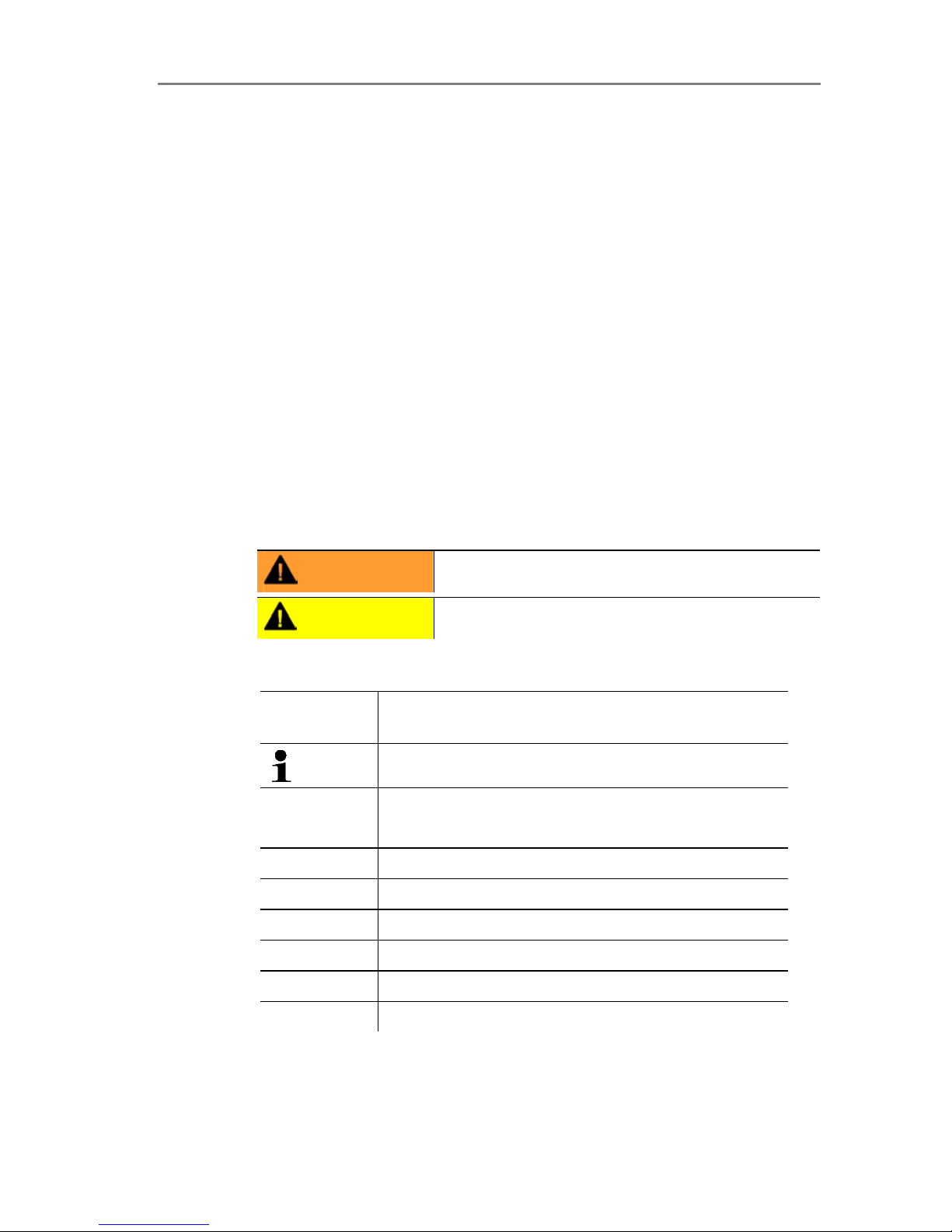
Maximum load
• 4-wire: 500 Ω (power output)
Page 10
4 Transmitter
10
Maximal load
• 4-wire: 10 kΩ (voltage output)
Analog output
• 0 to 1 V ± 1.5 mV (4-wire) or
• 0 to 5 V ± 7.5 mV (4-wire) or
• 0 to 10 V ± 15 mV (4-wire) or
• 0 to 20 mA ± 0.03 mA (4-wire) or
• 4 to 20 mA ± 0.03 mA (4-wire)
Resolution of analog output
• 12 bit
Relay
• 4 relays, 250 V AC/DC, 3 A (optional)
Display
• 2-line LCD with plain text line (optional)
Operating temperature
• -5 to 50 °C/23 to 122 °F
Page 11

4 Transmitter
11
Storage temperature
• -20 to 60 °C/-4 to 140 °F
Process temperature
• -20 to 65 °C/-4 to 149 °F
Oper. humidity
• 0 to 90 % RH
Housing, weight
• Metal/plastic
• Version with integrated humidity probe: approx. 1.35 kg
• Version with preparation for external humidity probe: approx.
1.26 kg
Protection class, frontal
• IP 65 only if the transmitter is wired and/or sealing plugs are
inserted
Directives, standards and tests
• EC Directive: 2004/108/EC
Warranty
• Duration: 2 years
• Warranty conditions: see website www.testo.com/warranty
Page 12
4 Transmitter
12
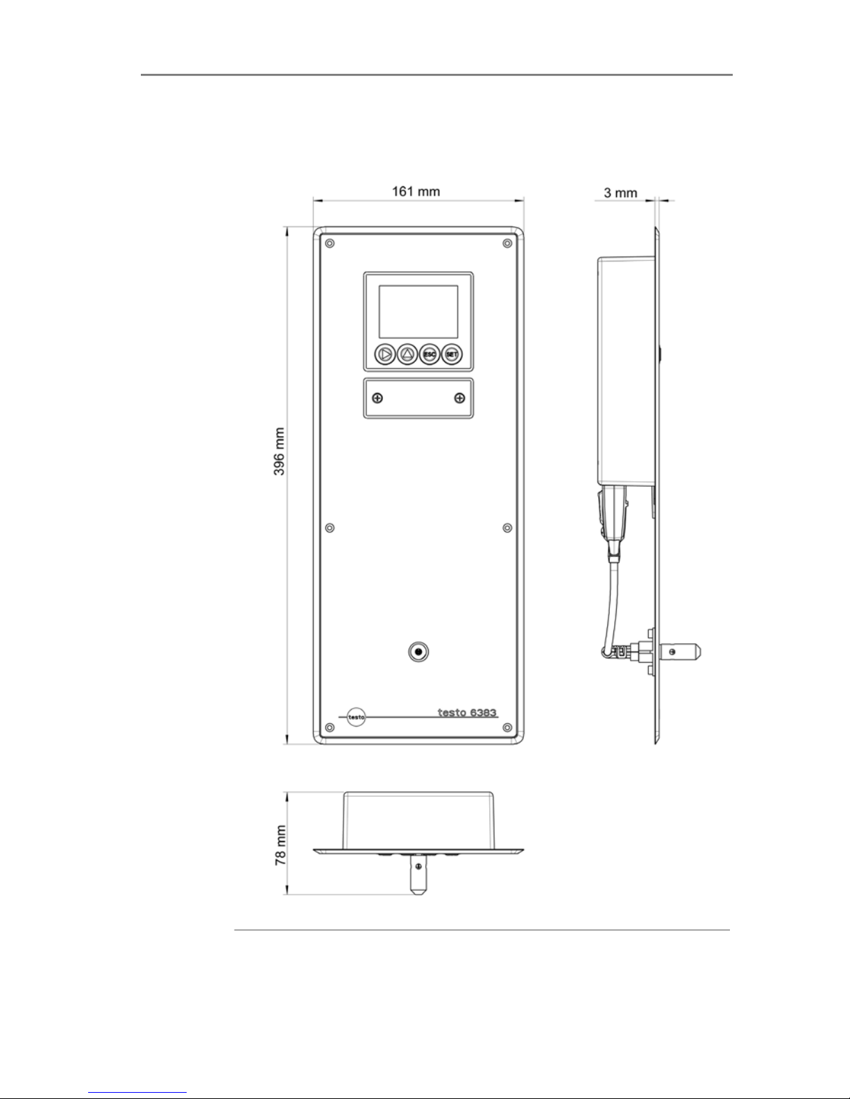
Pos: 25 /TD/Leistungsbeschreibung/ Technische Daten/MUF 63xx/MUF Panel lang Ab messungen @ 4\mod_1255092618418_79.doc @ 51743 @ 3
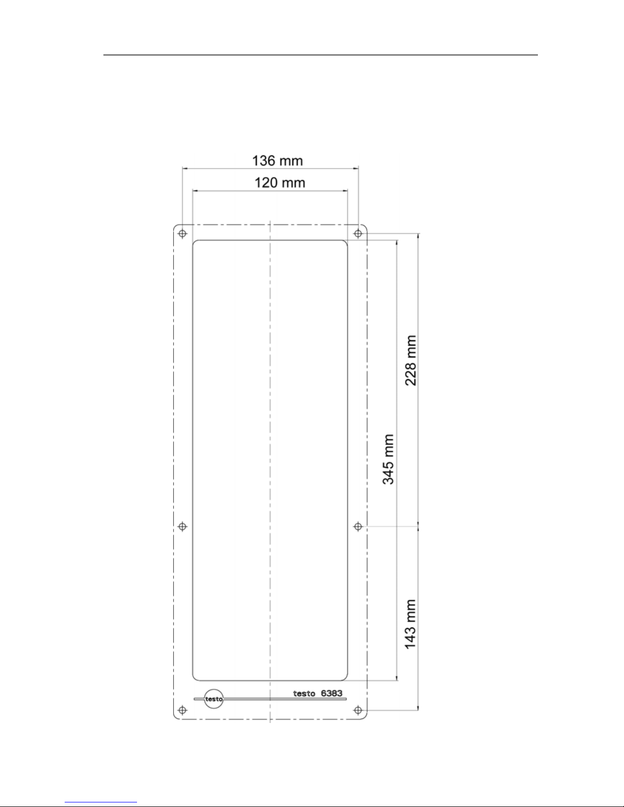
4.1.5. Dimensions
Page 13
4 Transmitter
13
Pos: 26 /TD/Überschriften/MUF/1.2/2. 2 P r oduktbeschreibung @ 3\mod_123425872 3551 _79.doc @ 24008 @ 2
4.2. Product description
Pos: 27 /TD/Produktbeschreibung/Übersi cht/MUF 63xx/Auf einen Blick 6383 @ 4\mod_1 252499456455_79.doc @ 48901 @ 3
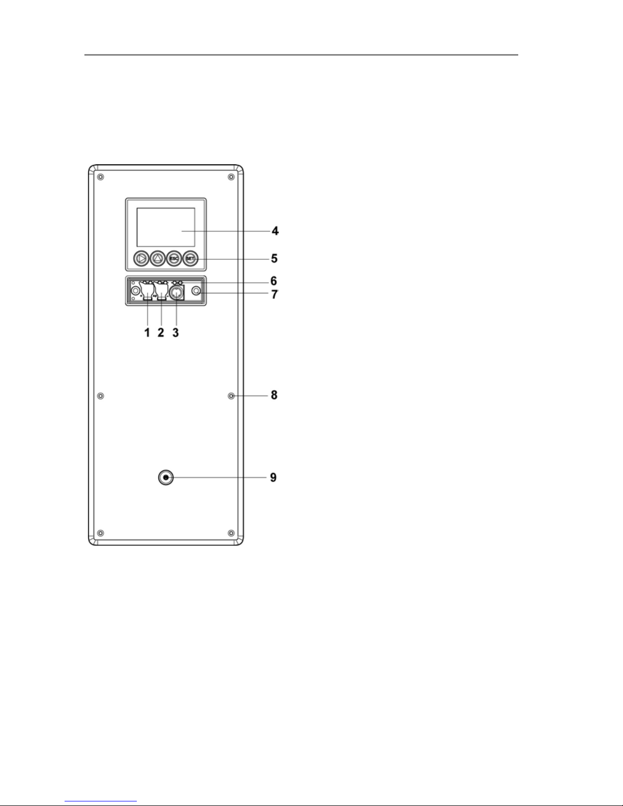
4.2.1. At a glance
1 Sealing plugs on the positive
pressure test connection
2 Sealing plugs on the
negative pressure test
connection
3 Socket for service plug
4 Display (optional)
5 Keys (only with optional
display)
6 Test rods for the analog
outputs
7 Service cover screw
connection (self-locking,
2 pcs.)
8 Openings for screws for
fastening to the wall
9 Only with integrated humidity
probe (KMAT option D04):
Opening for the integrated
humidity probe
Page 14
4 Transmitter
14
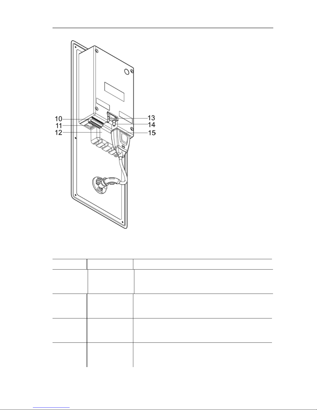
10 9-pin connector for the
current/voltage supply
11 Covered Ethernet interface
(non-functional)
12 Relay cover with 12-pin
connector underneath for
relay connection (option)
13 Negative pressure
connection
14 Positive pressure connection
15 Probe socket
Pos: 28 /TD/Produktbeschreibung/Übersi cht/MUF 63xx/Verwendbare Fühler Pane l @ 4\mod_1252670326817_79.doc @ 50119 @ 3
4.2.2. Usable probes
The testo 6383 transmitter can be used with the following probes:
Probes Article no. Characteristic
Integrated
humidity
probe
KMAT option
D04
Wall probe version; accuracy to ±1 % RH;
temperature range -20 to +70 °C/-4 to +158 °F,
plug-on sensor
testo 6612 0555 6610-L12
Duct probe version; accuracy to ±1 % RH;
temperature range -30 to +150 °C/
-22 to +302 °F, sensor soldered
testo 6613 0555 6610-L13
Cable probe version; accuracy to ±1 % RH;
temperature range -40 to +180 °C/
-40 to +356 °F, sensor soldered
testo 6614 0555 6610-L14
Heated cable probe version; accuracy to ±1.0 %
RH; temperature range -40 to +180 °C/
-40 to +356 °F, sensor soldered
Page 15

4 Transmitter
15
Probes Article no. Characteristic
testo 6615 0555 6610-L15
Trace humidity cable probe version; accuracy
±1 K at 0 °Ctd/+32 °Ftd; temperature range
-40 to 120 °C/-40 to +248 °F, sensor soldered
testo 6617 0555 6610-L17
Cable with cover electrode monitoring probe
version; accuracy to ± 1.2 % RH; temperature
range -40 to 180 °C/
-40 to +356 °F, sensor soldered
Pos: 29 /TD/Produktbeschreibung/Übersi cht/MUF 63xx/Display und Tastatur @ 3\ mod_1234773965059_79.doc @ 25650 @ 3
4.2.3. Display and keypad
The display option allows operation of the testo 6383 transmitter via
the display and four keys.
The LCD display consists of two 7-segment lines for displaying
readings and units and of an information line (for status messages,
for example).
The brightness and contrast of the display and the backgrou nd
lighting (permanent or off) can be changed via the user menu or the
P2A software.
Pos: 30 /TD/Überschriften/MUF/1.2. x Serviceschnittstelle @ 3\mod_12373068 91654_79.doc @ 29795 @ 3
4.2.4. Service interface
Pos: 31 /TD/Produktbeschreibung/Übersi cht/MUF 63xx/Serviceschnittste lle 638x @ 3\mod_1234774092911_79.doc @ 25669 @
The parameterizing socket (mini-DIN) is located behind the service
flap as an interface to the P2A software or Testo handheld
instrument (testo 400/testo 650).
Pos: 32 /TD/Produktbeschreibung/Übersi cht/MUF 63xx/Relaisplatine (Op ti on) @ 3\mod_1234774184843_79.doc @ 25688 @ 3
4.2.5. Relay board (option)
This has a floating switch capacity of 250 V AC/3 A. The switching
limits and hysteresis as well as the function as relay for the
collective alarm can be set via the display or the P2A software.
Further features include:
• Function of changeover contacts (NC/NO contacts) freely
selectable
• 12 terminals for a total of 4 relays.
If no relays are available, settings for monitoring limit values
or alarms can still be controlled via the display. The alarm
status will be shown on the display.
Only have the transmitter wired and connected by
authorized personnel with the voltage disconnected.
Page 16

4 Transmitter
16
Pos: 33 /TD/Produktbeschreibung/Übersi cht/MUF 63xx/Analogausgänge 638 x @ 3\mo d_1 234774341528_79.doc @ 25707 @ 3
4.2.6. Analog outputs
As analog outputs, the testo 6383 has either
• 1 or optionally 3 current outputs of 0 to 20 mA (4-wire)/4 to
20 mA (4-wire) or
• 1 or optionally 3 voltage outputs of 0 to 1 V/0 to 5 V/0 to 10 V
(4-wire).
The transmitter can be ordered with three analog outputs as an
option.
The optional three channels are galvanically isolated.
Pos: 34 /TD/Produktbeschreibung/Übersi cht/MUF 63xx/Messgrößen 6383/6385 @ 3\ m od_1 234774693900_79.doc @ 25745 @ 3
4.2.7. Parameters
The following parameters are displayed
• Differential pressure in Pa, hPa, kPa, mbar, bar, mmH
2
O, inch
H
2
O, inch HG, kg/cm2, PSI
• Relative humidity in % RH (technical)
• Relative humidity in % WMO* (calculation according to the
WMO standard)
• Degree of humidity in g/kg and gr/lb
• Absolute humidity in g/m³ and gr/ft³
• Water content in ppm (vol) and % vol
• Psychrometer temperature in °C
tw
and °Ftw
• Enthalpy in kJ/kg and BTU/lb
• Water vapour partial pressure in hPa and inch H
2
O
• Dewpoint temperature in °C
td
and °Ftd
• Standardized dewpoint in °C
tdA ,
standardized at atmospheric
pressure (1013 hPa); precondition: Absolute process pressure.
• Dewpoint of H
2O2
mixture in °Ctm and °Ftm.
* It is possible that condensation appears as of a displayed
humidity starting from 70 % and is shown on the display. This
unit is used in meteorology, amongst others. When calculating
the relative humidity the Magnus coefficient with undercooled
water is used in accordance with WMO.
Calculated humidity variables correspond to the medium of
air. With other gases/gas compositions, deviations may
occur, e.g. with the enthalpy.
• Temperature °C and °F
Page 17

4 Transmitter
17
Pos: 35 /TD/Produktbeschreibung/Übersi cht/MUF 63xx/Skalierung @ 3\mod_123477 5406989_79.doc @ 25783 @ 3
4.2.8. Scaling
There are three types of min./max. values:
1 The measuring range: The maximum sensor performance is in
this range. Values outside of the measuring range are displayed
via messages, for example. Measuring range, see table
(below).
2 Standard scaling: The output signals are assigned to this
measuring range as standard:
◦ during delivery if no entries are made in the order code
◦ after exchanging the un it, the measuring range recorded in
the instrument is applied as standard.
The transmitter even retains its scaling with the voltage
disconnected.
Measuring range, see table (below).
3 The maximum settings for the manual scaling
◦ The maximum limits can be calculated as follows:
X = difference between MIN. and MAX. value of the
standard scaling
(Max. value of standard) + (50 % of X)
(Min. value of standard) - (50 % of X)
◦ It is thus possible to scale beyond the measuring rang e, e.g.
for the adjustment of the scaling limits to standard values of
a PLC.
With the alarm definition, however, the physical measuring
range limits are decisive.
Pos: 36 /TD/Produktbeschreibung/Übersi cht/MUF 63xx/Tabelle Skalierung M UF Pan el Druck @ 4\mod_1251818135359_79.doc @ 48019 @
Measuring
range/standard scaling
Maximum scaling
0 to 50 Pa -5 to 15 Pa
0 to 50 Pa -25 to 75 Pa
0 to 100 Pa -50 to 150 Pa
0 to 500 Pa -250 to 750 Pa
0 to 10 hPa -5 to 15 hPa
-10 to 10 Pa -20 to 20 Pa
-50 to 50 Pa -100 to 100 Pa
-100 to 100 Pa -200 to 200 Pa
Page 18

4 Transmitter
18
Measuring
range/standard scaling
Maximum scaling
0 to 50 Pa -5 to 15 Pa
-500 to 500 Pa -1000 to 1000
-10 to 10 hPa -20 to 20 hPa
Pos: 37 /TD/Produktbeschreibung/Übersi cht/MUF 63xx/Tabelle Skalierung Fühl er Panel @ 5\mod_1257519388289_79.doc @ 52767 @
Physical
measuring range
at 1013 hPa
Standard scaling of
transmitter
measuring range
Parameter Unit Probes
MIN MAX MIN MAX
°C 6611 -20 +70 -20 +70
°F 6611 -4 +158 -4 +158
°C
6613,
6614,
6617
-40 +180 -40 +180
°F
6613,
6614,
6617
-40 +356 -40 +356
°C 6615 -40 +120 -40 +120
Temperature
°F 6615 -40 +248 -40 +248
°Ctd 6611 -20 +70 -80 +100
°Ftd 6611 -4 +158 -112 +212
°Ctd
6613,
6614,
6617
-20 +100 -80 +100
°Ftd
6613,
6614,
6617
-4 +212 -112 +212
°Ctd 6615 -60 +30 -80 +100
Dewpoint
°F
td
6615 -76 +86 -112 +212
g/m3
all
probes
0 600 0 2000
Absolute
humidity
gr/ft
3
all
probes
0 250 0 800
relative humidity % RH
all
probes
0 100 0 100
Page 19

4 Transmitter
19
Physical
measuring range
at 1013 hPa
Standard scaling of
transmitter
measuring range
WMO relative
humidity
% RH 0 100 0 100
°Ctm -20 +100 -20 +100
Mixture dewpoint
(H
2O2
)
°F
tm
-4 +212 -4 +212
g/kg
all
probes
0 13300 0 9500
Degree of
humidity
gr/lb
all
probes
0 93000 0 66500
kJ/kg -40 99999 -40 8000 Enthalpy
BTU/lb -18 43000 -18 3500
°Ctw -40 100 -40 180
Psychrometer
temperature
°Ftw -58 210 -40 356
ppm
(vol)
H
2
O
0 99999 0 99999 Water content
% vol 0 100 0 100
hPa 0 1000 0 7000
Water vapour
partial pressure
inchH2O 0 400 0 2800
Pos: 38 /TD/Produktbeschreibung/Übersi cht/MUF 63xx/Alarmbehandlung @ 3\mod _12 34776787635_79.doc @ 25821 @ 3
4.2.9. Alarm handling
For upper and lower alarm limits, individual alarms as well as
collective alarms can be specified. If the collective alarm function is
activated, an alarm is triggered as soon as the alarm limit of an
alarm is exceeded, if this alarm is assigned to the collective alarm.
The testo 6383 monitors limit values with the help of relays. If a
reading is outside the limit values, a relay to be specified by the
user is switched.
If the reading reverts to more than a specified hysteresis below or
above the limit value, the alarm is cancelled.
In addition, information about the occurrence of error/status
messages can be provided by means of a collective alarm relay,
see Status, warning and error messages, page 53
If multiple alarm messages are activated at the same time,
the last alarm is shown. If the alarm is cancelled again, the
previous messages are no longer shown.
Page 20
4 Transmitter
20
Pos: 39 /TD/Überschriften/MUF/1.3/2. 3 I nbetriebnahme @ 3\mod_1234258805768_7 9.doc @ 24027 @ 2
4.3. Commissioning
Pos: 40 /TD/Erste Schritte/MUF 63xx/W andm ont age Panel @ 4\mod_1251818568448_79.doc @ 48051 @ 3
4.3.1. Mounting preparations
Page 21

4 Transmitter
21
1. Create a wall opening (approx. 120 mm x 220 mm) at the
mounting location.
2. Hold 6383 in assembly position and mark the drill holes.
3. Drill holes suitable for the screws to be used.
4. Connect 6383.
Pos: 41 /TD/Erste Schritte/MUF 63xx/Gerä t anschließen Panel @ 4\mod_125206550656 6_79. doc @ 48245 @ 3
4.3.2. Connecting the instrument
WARNING
Electrical voltage
Danger of injury!
> De-energize the mains connection before connecting the
transmitter.
Only have the transmitter wired and connected by
authorized personnel with the voltage disconnected.
Page 22

4 Transmitter
22
Pos: 42 /TD/Erste Schritte/MUF 63xx/Ansc hlussübersicht 6383 @ 4\mod_125170832 7447 _79.doc @ 47697 @ 4
4.3.2.1. Overview of terminals
1 Terminal strip for voltage
supply and analog outputs
3 Relay cover (option)
2 Relay terminal strip (option),
below the relay cover
4 Insulating trough for relay
board (option), below the
relay cover
The following description of the terminals refer to this
overview and its numbering.
Pos: 43 /TD/Erste Schritte/MUF 63xx/Spannu ngsversorgung/Analogausgänge an sc hließen 6383/6385 @ 4\mod_1254489681844 _79.doc @ 51173 @ 45
Page 23

4 Transmitter
23
4.3.2.2. Connecting voltage supply and analog outputs
Terminal strip for voltage
supply and analog outputs,
item (1) of overview of
terminals
Wiring diagram for 4-wire system (0 to 20 mA/4 to 20 mA/0 to 1
V/0 to 5 V/0 to 10 V)
1 1 or 3 channels,
0 to 20 mA/4 to
20 mA max.
load per 500 Ω
0 to 1 V/0 to
5
V /
0 to 10 V
2 Functional earth
Requirement for the connecting cable of the supply:
• Shielded and insulated with cross-section of at least
0.25 sq. mm, maximum 1.5 sq. mm without wire end sleeves.
• T he supply line must be secured against exceeding
0.5 A.
• An OFF switch must be installed in an easily accessible
position close by and be marked as such.
1. Disconnect terminal strip for voltage supply and analog outputs.
2. Strip the cable ends, clamp wire end ferrules on and screw
down with voltage terminals/channel terminals.
3. Tie together each of the two adjacent cores using a cable tie.
4. Attach terminal strip for voltage supply and analog outputs.
Page 24

4 Transmitter
24
Pos: 44 /TD/Erste Schritte/MUF 63xx/Re lai sa usgänge anschließen Panel @ 4\mod_12518 14425917_79.doc @ 47891 @ 4555
4.3.2.3. Connecting the relay outputs
Only have the transmitter wired and connected by
authorized personnel with the voltage disconnected.
Relay terminal strip,
item (2) of overview of
terminals
There is the option of twelve terminals for a total of four relays.
1. Remove relay cover.
2. Disconnect relay terminal strip.
3. Strip cable ends and clamp on wire end ferrules.
4. Connect relays according to chosen function (NC/NO) (see
diagrams below; relay 1 is shown as an example of a
connection).
Connection note
• For the connection, a double-insulated mains cable
(sheathed cable) with a cross-section of at least 1.5
mm² must be used.
• Cable connection (2) may not be routed in a loop within
the relay trough (1).
Page 25

4 Transmitter
25
• It is recommended that you always tie 2 adjacent cores
to one another using a cable tie (3).
• T he insulation of the cable must be fed at least 5 mm
(4) into the relay tray up to the elevated part.
Use of relay as NC contact (NC = normally closed)
1 Alarm/status light
(example of installation)
2 250 V AC/DC, 3 A
The busy light (alarm/status light) is permanently on until
the relay opens or the circuit is interrupted. This circuit can
therefore be used to monitor the functionality of the alarm
circuit, as a cable break, for instance, is indicated by the
busy light going off.
Page 26

4 Transmitter
26
Use of relay as NO contact (NO = normally open)
1 Alarm/status light
(example of installation)
2 250 V AC/DC, 3 A
The busy light (alarm/status light) only comes on when the
relay is switched (closed). Monitoring the functionality of the
alarm circuit is therefore not possible with this switching
operation.
5. Insert relay terminal strip into socket.
6. Set on relay cover.
Page 27

4 Transmitter
27
Pos: 45 /TD/Erste Schritte/MUF 63xx/Gerä t schließen 6383 @ 4\mod_1252501761161_79.doc @ 48997 @ 4
4.3.2.4. Closing the instrument
1. Connect probe.
• Version with int egrated humidity probe:
1. Insert probe into probe socket.
2. Guide probe through opening of front plate.
3. Tighten screw at opening.
• Version with external h umid ity probe:
> Insert probe into probe socket.
Page 28

4 Transmitter
28
4. Pull sealing frame (1) over the edge of the 6383.
5. Screw on 6383. Initially, only tighten the screws slightly. When
all screws are in position, also align 6383 and tighten the
screws.
6. Seal 6383 using a measure appropriate for the installation point
(e.g. with a silicone strip).
Pos: 46 /TD/Erste Schritte/MUF 63xx/Gerä t abgleichen 6383/6385 @ 4\mod_1252502215678 _79.doc @ 49029 @ 4
Page 29

4 Transmitter
29
4.3.2.5. Adjusting the instrument
The testo adjusting concept allows the entire signal chain from the
sensor signal (probe) and the digital signal (within the transmitter)
through to the analog signal (transmitter output signal) to be
adjusted (see diagram).
1-point adjustment
Adjustment via
• testo 400/650
handheld instrument
with adjustment
adapter
• P2A software
• User menu
Analog adjustment n-point adjustment
Adjustment using a
precise multimeter and
transmission of analog
reference value in
• User menu or
• P2A software
Adjustment using a
precise pressure sensor
and transmission of
analog reference value in
• User menu or
• P2A software
The 1-point adjustment is suitable for adjusting the sensor signal digital signal chain.
The testo 6383 transmitter has digital probes whose adjustment
information is stored in the probes' internal memory. The 1-point
adjustment can thus be carried out on another testo 6383 (e.g. in
the calibration laboratory).
Page 30

4 Transmitter
30
Pos: 47 /TD/Erste Schritte/MUF 63xx/Übersi cht Abgleichtasten und Prüfkontak te 6383/6385 @ 4\mod_1252502914330_79.doc @ 49061 @ 4
4.3.2.6. Overview: Adjustment keys and test contacts
1 Contact ch. 1
2. Contact ch. 2
3. Contact ch. 3
4. Service interface
Pos: 48 /TD/Erste Schritte/MUF 63xx/1-Pun kt-Abgleich (Offset) @ 3\mod_1234790066 779_79.doc @ 26106 @ 45
4.3.2.7. 1-point adjustment (offset - humidity/temperature)
In the 1-point adjustment, the reading at the working point is raised
to the reference value so that there is no longer any deviation in the
working point. The reference condition can be measured using a
precise handheld instrument (e.g. testo 400/650 with precision
humidity probe) or be created in an air conditioning cabinet.
1 Deviation
2 Working point
3 Working range
The advantage of the 1-point adjustment is the good measuring
result in the working range. But the further away the measurement
is from the working point, the greater the deviation can become.
The 1-point adjustment should therefore only be used for a
Page 31

4 Transmitter
31
relatively narrow measuring range (working range), e.g. clean room
applications, air conditioning applications for storage and similar.
The 1-point adjustment can be performed
• via the user menu (see Editin g Main Menu Adjust, page 50) or
• via the P2A software (see volume 2, 1-point adjustment, page
122) or
• directly by means of a T esto handhel d instrument
(testo 400/650) (see description of how to proceed below).
Please note that the 1-point adjustment is generally performed on
the basis of the % RH and °C/°F parameters.
Adjusting testo 6383 using testo handheld instrument
✓ The service flap is open, a testo 400/650 handheld instrument
with a precision humidity probe is ready.
1. Connect testo handheld instrument 400/650 (1) with connected
humidity reference probe (3) (order no. reference set
0699 3656/20) to the service interface (5) of the testo 6383 via
the adjustment adapter (2) (connected to probe socket 1 of the
handheld instrument).
2. Expose the humidity probe (4) of the testo 6383 and the
reference probe (3) to the same reference conditions (e.g. in
the humidity generator) and allow climatic conditions to
equalize.
3. Switch on the testo 400/650. The two-part display of the
handheld instrument will show the values of the transmitter on
the left, and the values of the reference probe on the right. The
humidity and temperature values are adjusted to the reference
probe using the Probe > Probe Adjustment menu item on the
Page 32

4 Transmitter
32
testo 400/650. The 1-point adjustment is performed for both the
humidity and the temperature.
4. Disconnect the adjustment adapter (2) from the service
interface (5).
5. Close the service flap.
Pos: 49 /TD/Erste Schritte/MUF 63xx/Hin weis 6614, 6615 @ 3\mod_1234791706885_79.doc @ 26163 @
Adjustment with the standard testo adjustment salt pots is
not suitable for the testo 6614 (heated for high-humidity
applications) and testo 6615 (trace humidity) probes.
The reference conditions should be generated in a humidity
generator to adjust these probes. In addition, these probes
can also be adjusted at a third adjustment point by Testo
Service.
• testo 6614: third adjustment point at 90 % RH
• testo 6615: third adjustment point at -40 °Ctd/-40 °Ftd
Pos: 50 /TD/Erste Schritte/MUF 63xx/Analo gausgangs-Abgleich 6383/6385 @ 4\mod_125 2498044594_79.doc @ 48837 @ 45
4.3.2.8. Analog output adjustment
The purpose of adjusting the analog outputs is to adjust the signa l
chain from the digital signal (within the transmitter) to the analog
outputs. The signal type that was appointed for the transmitter is
adjusted respectively for each channel (e.g. 4 to 20 mA or 0 to 1 V,
etc.).
1 Contact ch. 1
2. Contact ch. 2
3. Contact ch. 3
4. Service interface
Page 33

4 Transmitter
33
Adjusting analog outputs 1, 2 and 3 (optional)
✓ With testo 6383 with current output: Load of max. 500 Ω is
connected to channel that is to be adjusted (see Connecting
voltage supply and analog outputs, page 23)
✓ A precise multi meter (minimum requirement: resolution 6.5
digits, at least 5-times more accurate than the 6383) is
available.
If only a simple multimeter is available, the analog outputs
must not be adjusted.
✓ The service cover is open.
1. Connect the inputs of the multimeter with the contacts (1) and
(2) for channel 1 or with contacts (3) and (4) for channel 2, (5)
and (6) for channel 3.
2. Transfer the reference analog value measured with the
multimeter into the P2A software (see volume 2, Adjusting the
analog output, page 125) or enter it via the user menu (see
Editing Main Menu Adjust, page 50).
3. Disconnect connections between the multimeter and the
contacts of the testo 6383 and close the service cover.
Pos: 51 /TD/Erste Schritte/MUF 63xx/n-Pun kt-Abgleich _638x @ 3\mod_1237384429887_ 79.doc @ 29990 @ 4
4.3.2.9. n-point adjustment (pressure)
With an n-point adjustment, the parameters at the 3-6
measurement points are adjusted to the reference value. T he
reference conditions are obtained by using a precise pressure
sensor that should be 5-times more accurate than the transmitter.
1 Positive pressure connection
2. Negative pressure connection
3. Pressure sensor
The number of measuring points is set to 3 by the factory
and can only be changed using the P2A software (see n-
point adjustment page 124)
Page 34

4 Transmitter
34
The n-point adjustment must always be carried out to its full
extent and in good time at all selected measurement points.
✓ A precise pr essure sensor (5-times more accurate than the
transmitter, e.g. DPC precision pressure sensor from testo
industrial services) is available.
1. Connect the positive output of the pressure sensor (3) to the
positive pressure connection of the transmitter (1) and the
negative output of the pressure sensor (3) to the negative
pressure connection of the transmitter (2).
2. Transfer the reference pressure value created with the pressure
sensor into the P2A software (see volume 2, n-point
adjustment, page 124) or enter it via the user menu (see Editing
Main Menu Adjust, page 50).
3. Repeat step 2 for all of the measuring points.
4. Disconnect connections between the pressure sensor and the
pressure connections of the testo 6383.
Pos: 52 /TD/Erste Schritte/MUF 63xx/Hochf euchteabgleich beim testo 6614 @ 3\mod_123 5661029461_79.doc @ 26922 @ 4
4.3.2.10. High-humidity adjustment for testo 6614
With the testo 6614, the rear of the Testo humidity sensor is
heated, creating a microclimate around the sensor (within the filter)
that is constantly 5 K warmer than the actual process conditions.
Page 35

4 Transmitter
35
As can be seen in the Mollier diagram, this reduces the relative
humidity at the sensor from around 100 % RH to a lower value, e.g.
73 % RH. In this range, the reaction time of the sensor is noticeably
shorter than in the condensation range and the risk of the sensor
corroding is also reduced. Using the separate temperature probe,
the testo 6383 transmitter compensates the microclimate conditions
and displays the process readings.
The reference conditions (11.3 % RH and 75.3 % RH) for
the 2-point adjustment of the testo 6614 should be
generated in a humidity generator, as humid ity adjustment
sets cannot be used due to the heat generated.
The adjustment can also be carried out at a third
adjustment point (90 % RH) by Testo Service so that
optimum accuracy is also achieved in the high humidity
ranges.
Pos: 53 /TD/Erste Schritte/MUF 63xx/Selb stabgleich des Restfeuchtefühlers tes to 6615 @ 3\mod_1235661074070_79.doc @ 26942 @ 4
4.3.2.11. Self adjustment of testo 6615 trace humidity probe
Conventional trace humidity probes show a steep rise in measuring
uncertainty at low humidities. In the testo 6615 trace humidity
probe, these measuring uncertainties are corrected by means of an
automatic self-adjustment process. This means that extremely
accurate measuring results are also attained to -60 °Ctd.
To this end, a temperature sensor is fitted on the back of the
testo 6615 which is used as a heater. A humidity and temperature
value pair is taken in both the unheated and heated state. The
deviation of the probe obtained from these pairs of values is
automatically corrected.
Page 36

4 Transmitter
36
The heating time and storing of cycles can be edited in the P2A
software; for example, they can be deactivated by setting the two
parameters to "0".
• Deactivating th e adjustment function of the testo 6615
will reduce measuring accuracy and should therefore be
restricted to the shortest possible length of time.
• During the heating phase, the relay and analog outputs,
the display value and output value are "frozen", see
diagram above. Self-adjustment active is shown in the
display until it has finished. The factory setting for selfadjustment time (incl. heating time, calculation time,
cooling time) requires 30 minutes daily.
• In the factory setting, a third adjustment point
(-40 °Ctd) is approached for the testo 6615 in addition
to the 2-point adjustment. This special adjustment can
be performed again by your Testo Service team if
necessary.
Pos: 54 /TD/Überschriften/MUF/1.4 Bedi enung @ 3\mod_1234443160034_79.doc @ 25001 @ 2
4.4. Operation
Pos: 55 /TD/Produkt verwenden/MUF 63xx/Zusa mmenhang Bedienmenü – Mini DIN Buchse akti v @ 3\mod_1234454016014_79.doc @ 25213 @ 3
4.4.1. Relationship between user menu and mini-DIN
socket is active
The testo 6383 can be parameterized using either the user menu or
the P2A software (see volume 2, Parameterizing, adjusting and
analyzing software (P2A software) page 101).
The testo 6383 transmitter can only be operated via the
display and keypad if the display option is available.
If the testo 6383 is connected to the P2A software, the user
menu is blocked for the duration of the communication. The
message Service plug is shown in the display of the testo
6383. As soon as the P2A software is disconnected, the
user menu is accessible again.
Pos: 56 /TD/Produkt verwenden/MUF 63xx/Pass wortschutz _638x @ 3\mod_1234455136144 _79.doc @ 25251 @ 3
4.4.2. Password protection
The user menu can be protected with a four-digit numerical code
(see Editing Main Menu Settings, page 44) so that access to the
user menu is denied to unauthorized persons not familiar with this
numerical code.
If the password protection is not to be used, the numerical code
"0000" must be entered. This is also the status upon delivery.
Page 37

4 Transmitter
37
Pos: 57 /TD/Produkt verwenden/MUF 63xx/Auf bau des Bedienmenüs 638x @ 3\mod_1234455236596 _79.doc @ 25270 @ 3
4.4.3. Structure of user menu
At the main menu level, the user menu comprises the following:
• Main Menu Channel 1
• Main menu of channel 2 (if this option is available)
• Main menu of channel 3 (if this option is available)
• Main Menu Alarm
• Main Menu Settings
• Main Menu Analysis
• Main Menu Messages
• Main Menu Ident
• Main Menu Adjust
• Main Menu Reset
1 Channel 1 display
2 Channel 2 display
3 Channel 3 display or for
messages
Four keys enable the user to navigate/scroll through the menus and
enter/amend values and settings:
Key Function/description
SET
• In Measuring Mode: changes to
parameterization
• In Parameterizing Mode: confirms a
selection or setting
ESC
• Leaves a menu (without modifying any
settings)
X • Selecting: scrolls through menus
(downwards) or selectable alternatives
• Editing: chang es to ne xt digit (to the right)
Page 38

4 Transmitter
38
Key Function/description
S • Selecting: scrolls through menus (upwards)
or selectable alternatives
• Editing: increa ses t he value of the current
digit by 1
Pos: 58 /TD/Produkt verwenden/MUF 63xx/Über sicht Bedienmenü @ 3\mod_1234510821302 _79.doc @ 25303 @ 3
4.4.4. Overview of the testo 6383 user menu
Page 39

4 Transmitter
39
Page 40

4 Transmitter
40
Page 41

4 Transmitter
41
Pos: 59 /TD/Produkt verwenden/MUF 63xx/Haup tmenü Kanäle bearbeiten @ 3\mod_12345111 1915 8_79.doc @ 25322 @ 34
4.4.5. The individual main menus
4.4.5.1. Editing main menu of channel 1
An overview is given in Overview of the testo 6383 user menu,
page 38).
You can perform basic settings for channel 1.
1. In the Measuring Mode press SET, select Main Menu
Channel 1 with X or S and confirm selection with SET.
One of the following parameters can now be selected using X
or S, after which the selection must be confirmed with SET:
• Channel 1 Unit
The parameter for this channel is selected.
Edit/select parameter with X or S, confirm with SET or abort
entry with ESC.
• Scale minimum for channel 1:
The lower scale limit is edited; Unit as selected above.
Editing the value: Scroll one digit to the right using X and
increase value of digit by 1 using S. Confirm with SET or abort
entry with ESC.
• Scale maximum for channel 1
The upper scale limit is edited;
Unit as selected above.
Editing the value: Scroll one digit to the right using X and
increase value of digit by 1 using S. Confirm with SET or abort
entry with ESC.
• Signal delay ("Attenuation") for channel 1
The analog signal can be delayed ("Attenuation"); a time
constant is selected for this (1 = no delay; 15 = longest delay)
Edit/select parameter with X or S, confirm with SET or abort
entry with ESC.
2. Continue to the main menu with X or S or return to Measuring
Mode with ESC.
Pos: 60 /TD/Produkt verwenden/MUF 63xx/Haup tmenü Kanal 2/3 638x @ 3\mod_1236085000820_79. doc @ 27312 @ 44
4.4.5.2. Editing Main Menu Channel 2 (if this option is available)
See channel 1.
Page 42

4 Transmitter
42
4.4.5.3. Editing Main Menu Channel 3 (if this option is available)
See channel 1.
Pos: 61 /TD/Produkt verwenden/MUF 63xx/Haup tmenü Alarm bearbeiten 638x @ 3\mod_123451 8541 385_79.doc @ 25341 @ 455
4.4.5.4. Editing Main Menu Alarm
With the alarm, the relays, available as options, are programmed.
In addition, the alarm statuses are shown on the display (top right)
(even without relays).
You can choose whether the alarm is to be used to monitor limit
values or as a collective alarm. If an alarm is to be used to monitor
limit values, you can choose between monitoring the minimum or
maximum value and set a limit value and hysteresis for each alarm.
In addition, every alarm can be linked to a clearly visible visual
alarm (display background lighting flashes).
An alarm delay between 0 and 240 seconds can still be assigned to
every alarm used for limit value monitoring so that both the
corresponding relay effect and the visual alarm are delayed. If the
alarm status goes out within the set alarm delay time, neither the
visual alarm nor a relay connection is triggered. .
With an alarm status present, the visual alarm and all relay outputs
can be reset by means of acknowledgement. The triggering of a
new alarm cannot be enabled until after the alarm status goes out.
1. In the Measuring Mode press SET, select Main Menu Alarm
with X or S and confirm select ion with SET.
- F our alarms can be parameterized.
2. Select Alarm x with X or S and confirm sele ction with SET.
Using alarm to monitor limit values
NO contact
Monitoring minimum Monitoring maximum
Hysteresis
Hysteresis
Limit value Limit value
Page 43

4 Transmitter
43
NC contact
Monitoring minimum Monitoring maximum
Hysteresis
Hysteresis
Limit value Limit value
3. Select Channel x (e.g. "Channel 1") with X or S and confirm
selection with SET.
4. Select Max control or Min control with X or S (see graphic).
5. Press SET and edit Limit value as well as Hysteresis: Scroll
one digit to the right using X and increase value of digit by 1
using S. Confirm with SET or abort entry with ESC.
6. Select Visual alarm with X or S. Select YES or NO wit h X or
S. Confirm with SET or abort entry with ESC.
7. Press SET and edit Alarm delay: Scroll one digit to the right
using X and increase value of digit by 1 using S (0 to 240
seconds possible). Confirm with SET or abort entry with ESC.
8. Return to Channel x with ESC.
9. Return to Alarm x with ESC.
10. Change to the other relays using X or S and perform settings
in the same
wa
y.
Using alarm as collective alarm or not using it at all
If an alarm is assigned to the collective alarm, the relay is switched
and a visual alarm can be issued via the display as soon as (at
least) one of the warning or error messages of the testo 6383
transmitter (or the connected testo 6610 probe) becomes active.
The messages affecting the collective alarm can only be
selected in the P2A software, see volume 2, Using the
software, page 104
✓ Alarm is selected (see previous steps 1 and 2).
1. Use X or S to determine whether Alarm x should be used as a
Collective alarm or not used. Confirm selection with SET.
2. If collective alarm is selected: Select Visual alarm with X or S.
Select YES or NO with X or S. Confirm with SET and return to
Alarm x.
Page 44

4 Transmitter
44
3. Change to another alarm using X or S and perform settings in
the same way.
4. Return to Main Menu Alarm with ESC.
5. Continue to Main Menu Settings with X or S or return to
Measuring Mode with ESC.
Pos: 62 /TD/Produkt verwenden/MUF 63xx/Haup tmenü Einstellungen bearbeiten 6383/6 385 @ 4\mod_1252503503580_79.doc @ 49125 @ 4555 55
4.4.5.5. Editing Main Menu Settings
You can edit instrument settings and other settings.
> In Measuring Mode, press SET, select Main Menu Settings
using X or S and confirm selection with SET.
You can edit settings for:
• Display
• Language
• Code
• Units
◦ Absolute pressure
◦ Area
◦ Temperature
• Humidity process data
◦ H2O2 percentage by weight
◦ Humidity process pressure
Editing display settings
You can set the brightness and contrast of the display.
1. Select Display Settings with X or S and confirm selection wit h
SET.
2. Select Backlight or Contrast with X or S and confirm
selection with SET.
One of the following parameters can now be selected using X or
S, after which the selection must be confirmed with SET:
• Backlight
The display illumination is changed.
Edit/select parameter with X or S, confirm with SET or cancel
entry with ESC (the effect of the change in parameter can be
seen during input).
• Contrast
Page 45

4 Transmitter
45
The brightness difference between the display background and
the displayed values is changed.
Edit/select parameter with X or S, confirm with SET or cancel
entry with ESC (the effect of the change in parameter can be
seen during input).
• Backlight 24h o n
Select On or Off using X or S and confirm with SET.
Off: The display light switches off automatically if no button was
pressed for 10 seconds.
On: The display light is activated
3. Return to Display Settings with ESC and useX or S to
continue to Language.
Selecting language
You can select the language for the plain text line in the display.
> Press SET, select required language with X or S, confirm
selection with SET and return to Language.
Only choose a language that you can understand well.
Editing code settings
You can set the access code (password).
If a code other than "0000" (factory setting) is set, the
transmitter can only be operated once this code has been
entered via the menu.
1. Select Code with X or S and confirm selection with SET.
2. Scroll one digit to the right using X and increase value of digit
by 1 using S. Confirm with SET or abort entry with ESC.
3. Return to Code with ESC and useX or S to continue to
Change parameters.
Select unit (Change unit)
This setting affects the displayed unit of all readings.
1. Press SET, select Change parameters with X or S, confirm
selection with SET or cancel with ESC.
2. Select Change unit with X or S, confirm selection with SET or
cancel with ESC.
Page 46

4 Transmitter
46
3. Select the required variable (absolute
pressure/area/temperature) with X or S, confirm selection with
SET or cancel with ESC.
4. Select the required unit with X or S, confirm selection with SET
or cancel with ESC.
5 Return to Change unit with ESC.
6. Return to Change parameters with ESC.
7. Return to Main Menu Settings with ESC.
Editing Humidity process data
This menu is only used to parameterize humidity measurem ents in
H
2O2
atmospheres (e.g. in sterilization processes) and determines
whether °Ctm or °Ftm is the output parameter.
1. Select Humidity process data with X or S and confirm
selection with SET.
2. Select H202 weight prop. with X or S, confirm selection with
SET or cancel with ESC.
The selection H
2O2
water or H2O2 vapour in the submenu
describes whether H2O2 is generated by means of evaporation
or is actively vaporized in the process.
3. Select H
2O2
water or H2O2 vapour with X or S and confirm
with SET.
4. Edit proportion by weight of the H
2O2
in % (% H2O2 proportion
by weight in the liquid initial solution): Scroll one digit to the right
using X and increase value of digit by 1 using S. Confirm with
SET or abort entry with ESC.
5. Return to H202 weight prop. with ESC and useX or S to
continue to Humidity process pressure.
6. Select Humidity process pressure with X or S and confirm
selection with SET.
7. Edit humidity process pressure: Scroll one digit to the right
using X and increase value of digit by 1 using S. Confirm with
SET or abort entry with ESC.
8. Return to Change parameters with ESC.
9. Return to Main Menu Settings with ESC.
Pos: 63 /TD/Produkt verwenden/MUF 63xx/Haup tmenü Analyse bearbeiten 6383/6385 @ 4\mod_1 252507887718_79.doc @ 49449 @ 45555
Page 47

4 Transmitter
47
4.4.5.6. Editing Main Menu Analysis
You can test the functionality of analog and rela y outputs. In
addition, you can read off the minimum and maximum values (since
the last voltage supply or reset of the min./max. values).
Testing functionality of analog outputs
This function affects the analog outputs directly, not only
the test contacts.
1. In the Measuring Mode press SET, select main menu Analysis
with X or S and confirm select ion with SET.
- Test Analog Output is shown.
2. Press SET and choose between Analog output 1, 2, 3 with X
or S.
3. Press SET, scroll one digit to the right using X and increase
value of digit by 1 using S. Any analog output value can be
predefined, e.g. for an analog output of 4 to 20 mA, the value
"6.0 mA". Confirm with SET or abort entry with ESC.
4. Accept setting by pressing SET and test with multimeter
(minimum requirement: resolution 6.5 digits, at least 2-times
more accurate than the 6383) as follows:
Analog output 1, 2 or 3: Via test contacts under service cover,
see diagram.
1 Positive test
contact
channel 1
2 Negative test
contact
channel 1
3 Multimeter
4. Return to Test Analog Output with ESC and useX or S to
continue to Test Relay Output.
Page 48

4 Transmitter
48
Testing functionality of the pressure sensor (Test pressure
sensor)
This function is only required to calibrate the pressure
sensor.
Testing functionality of relay outputs
1. Press SET and choose between Alarm 1, 2, 3, 4 with X or S.
2. Press SET.
The relay can now be tested. You can choose between OFF
and ON using X or S. If ON is chosen, the NO contact is
closed, the NC contact opened. If OFF is chosen, the NC
contact is closed, the NO contact opened.
3. To test, route a measuring cable from the relay terminals (see
Connecting the relay outputs, page 24) out of the transmitter to
a multimeter (resistance measurement) or continuity tester.
4. Return to Test Relay Output with SET (starts relay test) or
ESC (exits the menu without relay test).
Reading off min./max. values of channels
To reset the max./min. values, see Editing Reset main menu, page
52
1. Read off the min./max. values of the three channels in
succession with X or S and return to the Main Menu Analysis
with ESC.
2. Continue to Main Menu Message with X or S or return to
Measuring Mode with ESC.
Pos: 64 /TD/Produkt verwenden/MUF 63xx/Haup tmenü Meldungen bearbeiten @ 3\mod_123452 6541417_79.doc @ 25398 @ 4
Page 49

4 Transmitter
49
4.4.5.7. Editing Message main menu
Messages can be confirmed/acknowledged, the last messages can
be called up and the display of the messages can be switched on
or off.
1 Operating hours at the
time of message
2 Message code (see
Status, warning and error
messages, page 53).
3 Message text
4 Message number
(example: "4/7" refers to
the fourth of seven
messages)
5 Number of messages
present (example: "4/7"
refers to the fourth of
seven messages)
Using the P2A software (see volume 2, Parameterizing,
adjusting and analyzing software (P2A software), page 101 )
you can predefine whether messages are to be shown in
the display.
1. In the Measuring Mode press SET, select Main Menu Message
with X or S and confirm select ion with SET.
2. Confirm Confirm message using SET.
3. Select Last messages with X or S and confirm with SET.
4. Scroll between the warning and error messages recorded so far
using X or S and return to Last messages using ESC.
5. Select Information with X or S and confirm with SET.
6. Scroll between the status messages recorded so far using X or
S and return to Information using ESC.
7. Continue to Display of message with X or S.
ON: Measurements are shown on the display in Measuring
Mode.
OFF: No messages shown on display.
8. Select ON or OFF with X or S and confirm selection with SET.
9. Return to Main Menu Message with ESC.
Page 50

4 Transmitter
50
10. Continue to Main Menu Ident with X or S or return to
Measuring Mode with ESC.
An overview of the messages can be found in Status,
warning and error messages, page 53
Pos: 65 /TD/Produkt verwenden/MUF 63xx/Haup tmenü Ident abfragen 638x @ 3\mod_12345269 9773 1_79.doc @ 25417 @ 4
4.4.5.8. Calling up Main Menu Ident
1 Instrument or
probe type
2 Build number
3 Firmware
version
4 Serial number
The serial numbers of the transmitter and probe can be read off.
1. In the Measuring Mode press SET, select Main Menu Ident
with X or S and confirm select ion with SET.
- The type, firmware version, build number and serial number of
the transmitter are displayed.
This information is required when servicing.
2. Return to Main Menu Ident with ESC or read off the type,
firmware release, build number and serial number of the probe
with X or S and then return to Main Menu Ident with X or S.
3. Continue to Main Menu Adjust with X or S or return to
Measuring Mode with ESC.
Pos: 66 /TD/Produkt verwenden/MUF 63xx/Haup tmenü Abgleich bearbeiten 6383/6385 @ 4\ mod _12 52503280594_79.doc @ 49093 @ 4555
4.4.5.9. Editing Main Menu Adjust
A reference value can be entered for both relative humidity (RH)
and temperature (°C/°F) for the 1-point adjustment. Please refer to
the description in 1-point adjustment (offset humidity/temperature), page 30
Reference values for pressure can be entered for the n-point
adjustment. Please refer to the description in n-point adjustment
(pressure), page 33
Page 51

4 Transmitter
51
In addition, the analog outputs can be adjusted. Also see Analog
output adjustment, page 32 for instructions on how to do this.
Enter reference value for 1-point adjustment
Please also refer to 1-point adjustment (offset humidity/temperature), page 30
1. In the Measuring Mode press SET, select main menu Adjust
with X or S and confirm select ion with SET.
- Reference value % RH is displayed.
2. Press SET, edit value: Scroll one digit to the right using X and
increase value of digit by 1 using S. Confirm with SET or abort
entry with ESC.
3. Continue to Reference value temp with X or S.
4. Press SET, Reference value °C or Reference value °F is
displayed.
5. Press SET, edit value: Scroll one digit to the right using X and
increase value of digit by 1 using S. Confirm with SET or abort
entry with ESC.
6. Continue to Analog Adj. Ch. 1 with X or S.
7. Continue with the adjustment of the analog outputs (see belo w,
step 2) or press ESC to return to main menu Adjust.
8. Continue to main menu Reset with X or S or return to
Measuring Mode with ESC.
Performing analog adjustment
Please refer to Analog output adjustment, page 32.
1. In the Measuring Mode press SET, select main menu Adjust
with X or S and confirm select ion with SET.
Each channel is adjusted at three points in the analog
range (at 10 %; 50 %; 90°% of the analog scale).
2. Select Analog Adj. Ch. 1 with X or S and confirm with SET.
3. Use X or S to select Adj. Point 1.
4. Press SET. Read off multimeter display (e.g. 5601 mA) and
enter this value in the user menu. Do this by scrolling one digit
to the right using X and increasing the value of digit by 1 using
S. Confirm with SET or abort entry with ESC.
5. Use X or S to select Adj. Point 2.
6. Press SET. Read off multimeter display (e.g. 12,001 mA) and
enter this value in the user menu. Do this by scrolling one digit
Page 52

4 Transmitter
52
to the right using X and increasing the value of digit by 1 using
S. Confirm with SET or abort entry with ESC.
7. Use X or S to select Adj. Point 3.
8. Press SET. Read off multimeter display (e.g. 18,401 mA) and
enter this value in the user menu. Do this by scrolling one digit
to the right using S and increasing the value of digit by 1 using
X. Confirm with SET or abort entry with ESC.
9. With X or S continue to Analog Adj. Ch. 2or 3 (repeat steps 3
to 8).
10. Return to main menu Adjust with ESC.
11. Continue to main menu Reset with X or S or return to
Measuring Mode with ESC.
Performing the pressure adjustment
Please refer to n-point adjustment (pressure), page 33.
1. In the Measuring Mode press SET, select main menu Adjust
with X or S and confirm select ion with SET.
The pressure adjustment can be performed at 3 to 6
adjustment points.
2. Select Adjust Pressure with X or S and confirm with SET.
3. Use X or S to select Adj. Point 1.
4. Press SET. Read off pressure sensor display (e.g. 30.1 Pa) and
enter this value in the user menu. Do this by scrolling one digit
to the right using X and increasing the value of digit by 1 using
S. Confirm with SET or abort entry with ESC.
5. Repeat steps 1 to 4 for adjustment points 2 to 6.
6. Return to main menu Adjust with ESC.
7. Continue to main menu Reset with X or S or return to
Measuring Mode with ESC.
Pos: 67 /TD/Produkt verwenden/MUF 63xx/Haup tmenü Reset bearbeiten 638x @ 3\mod_123452 9155 827_79.doc @ 25455 @ 4
4.4.5.10. Editing Reset main menu
You can reset the factory settings for the following:
• Instrument
• Sensor/probe
• Min./max. values
Resetting to the factory settings means resetting to the
order specification, i.e. the specific condition at the time of
supply to the customer.
Page 53

4 Transmitter
53
1. In the Measuring Mode press SET, select Main Menu Reset
with X or S and confirm select ion with SET.
- Reset Device to factory settings is displayed.
2. Select the setting to be reset using X or S and confirm
selection with SET.
- Reset Completed is displayed.
3. Return to the reset setting with ESC or SET and return to Main
Menu Reset with ESC.
4. Continue to Main Menu Channel 1 with X or S or return to
Measuring Mode with ESC.
Pos: 68 /TD/Überschriften/MUF/1.5 Sta tus-, Warn- und Fehlermeldungen @ 3\mod_123444 2925442_79.doc @ 24963 @ 2
4.5. Status, warning and error messages
Pos: 69 /TD/Produkt verwenden/MUF 63xx/Sta tus-Warnmeldungen/Status-, W arn- und Fehlermeldungen 638x @ 3\mod_1234441087981 _79.doc @ 24844 @
To achieve optimum operational reliability (machine ava ilability),
the transmitter shows the following via the user menu or the P2A
software
• Status messages
• Warning messages
• Error messages
The status and warning messages for the respective testo 6610
probes connected to the transmitter can be evaluated via the P2A
software.
All messages are stored in the transmitter with an operating hours
stamp. Use the user menu (see Editing Message main menu, page
49) or the P2A software (see volume 2, Transmitter history, page
126) to view the message history.
In the transmitter, the last 60 status messages and the last 120
error and warning messages are stored in a ring memory. There is
no limit in the P2A software.
Pos: 70 /TD/Produkt verwenden/MUF 63xx/Sta tus-Warnmeldungen/Statusmeldung en 6383/6385 @ 4\mod_1252506138420_79.doc @ 49257 @ 3
Page 54

4 Transmitter
54
4.5.1. Status messages
Status messages show the current operating status of the testo
6383.
Message Display Description
02506
Sensor
initialization
Message appears while the
transmitter is starting up. If the
message disappears, the
transmitter is ready for operation.
01D19 Service plug
The Mini-DIN socket is connected
to: the USB adapter for P2A
software, the adjustment adapter
or the service plug (is not
recorded/no number)
00300 New limit value
The limit value has been changed
or shifted
00301 Scaling changed The scaling has been changed
00500 Transmitter reset
The transmitter was reset to the
factory settings and is restarted.
0052F Reset Min/Max
Resets all saved Min/Max values
for all channels
02518 Probe reset
Probe reset: The probe performs a
reset
00503
Reset device to
fact
A factory reset of the transmitter
was performed
02503
Reset probe to
fact
A factory reset of the probe was
performed
00530
Change solenoid
valve
The solenoid valve should be
changed
00307
User Setting
Change
User Setting Change: General
settings were changed for the
transmitter.
00117 Adjustment DeltaP
An n-point adjustment was
performed.
02104 Analog adjustment
An analog adjustment has been
made
02101 1-point adjustment A 1-point adjustment is performed.
Page 55

4 Transmitter
55
Message Display Description
02105
Self-adjustment
active
For testo 6615 probe only: The
probe performs an automatic selfadjustment
Pos: 71 /TD/Produkt verwenden/MUF 63xx/Sta tus-Warnmeldungen/Warnmeldungen 6 383/ 6385 @ 4\mod_1252506208031_79.doc @ 49289 @ 3
4.5.2. Warning messages
Warning messages show an early warning or a current malfunction
which may negatively impact measuring.
Message Display Cause Remedying of fault
00809
Pressure too
high**
The process pressure
exceeds the pressure
intended for the
transmitter
Remove the transmitter
from the process and
take any necessary
measures to lower the
pressure
00E00 T ambient high**
The ambient
temperature exceeds
the permissible
temperature for the
transmitter
Take necessary
measures to lower
ambient temperature,
e.g. through venting or
cooling
00E01 T ambient low**
The ambient
temperature is below
the permissible
temperature for the
transmitter
Take necessary
measures to raise
ambient temperature,
e.g. through heating
00E04/00E
05
Supply voltage
low**
The supply voltage is
below the minimum
voltage required for the
transmitter
Take measures to
ensure sufficient
voltage supply
02822 T process high**
The process
temperature exceeds
the temperature
designated for the
probe
Remove the probe from
the process and take
any necessary
measures to lower the
process temperature
02821 T process low**
The process
temperature is below
the temperature
designated for the
probe
Take necessary
measures to raise
process temperature
0081C Alarm 1**
Depending on the
parameterization of the
relays
Depending on the
parameterization of the
relays
Page 56

4 Transmitter
56
Message Display Cause Remedying of fault
0081D Alarm 2**
Depending on the
parameterization of the
relays
Depending on the
parameterization of the
relays
0081E Alarm 3**
Depending on the
parameterization of the
relays
Depending on the
parameterization of the
relays
0081F Alarm 4**
Depending on the
parameterization of the
relays
Depending on the
parameterization of the
relays
02806 Condensation*
100 % RH has been
reached, condensation
developing
Take measures to
reduce process
humidity
02807
Values less than
0 % RH**
The adjustment or
sensor is faulty
Check adjustment (via
P2A adjustment history,
perform 2-point
adjustment where
necessary). If the
problem persists,
contact Testo Service
02809
Sensor early
warning*
For testo 6617 probe
only: The cover
electrode of the sensor
is damaged; this may
soon cause the sensor
to break
Carry out visual
inspection. If the mirrorlike surface of the
sensor is dirty or
damaged, contact
Testo Service
* Early warning
** Current malfunction
Pos: 72 /TD/Produkt verwenden/MUF 63xx/Sta tus-Warnmeldungen/Fehlermeldung en Messumformer 638x @ 3\mod_123453585107 6_79. doc @ 25512 @ 3
4.5.3. Transmitter error messages
Error messages show a current malfunction.
Message Display Cause Remedying of fault
03401 No probe signal
The probe
communication is
interrupted
Ensure that the probe
connector is fully
engaged in the
transmitter.
If communication still
cannot be established,
contact Testo Service
Page 57

4 Transmitter
57
Message Display Cause Remedying of fault
03508 Wrong probe
The connected probe
is not compatible with
the present transmitter
Use a compatible probe
Note: Probe 661x for
transmitter 638x
01505 Watchdog error
Due to a processor
error, the transmitter
performs an automatic
restart
If the problem occurs
frequently, contact
Testo Service
0300A
% RH shortcircuit
Short-circuit in humidity
sensor
Contact Testo Service
0300B
% RH sensor
broken
The humidity sensor is
damaged (sensor
broken)
Contact Testo Service
0300C T short-circuit
Short-circuit in
temperature sensor
Contact Testo Service
0300D T sensor broken
The temperature sensor
is damaged (sensor
broken)
Contact Testo Service
03105
Self-adjustment
error
For testo 6615 probe
only: The automatic
self-adjustment was
faulty
Contact Testo Service
03106 Adjustment error
The adjustment of the
probe was faulty
Contact Testo Service
01115
Low adjustment
temperature
The ambient
temperature is too low
during the pressure
adjustment
Take necessary
measures to raise
ambient temperature,
e.g. through heating
01116
High adjustment
temperature
The ambient
temperature is too high
during the pressure
adjustment
Take necessary
measures to lower
ambient temperature,
e.g. through venting.
03000
Heat function
defective
For testo 6614 probe
only: Heat function
defective
Contact Testo Service
Page 58

4 Transmitter
58
Pos: 73 /TD/Produkt verwenden/MUF 63xx/Sta tus-Warnmeldungen/Behandlung von Alar mmeldungen 6383/6385 @ 4\mod_12525062849 72_79.doc @ 49321 @ 3
4.5.4. Handling alarm messages
Shown on the
display
3
Can be used for
collective alarm4
Additional
message end5
New limit value x
Scaling changed x
Pressure too high x x
Delta p adjustment x
Alarm 1 x
Alarm 2 x
Alarm 3 x
Alarm 4 x
Transmitter reset x
Reset Min/Max
Transmitter refresh x
User Setting Change
Analog adjustment x
1-point adjustment x
Probe reset x
T ambient high x x
T ambient low x x
Supply voltage low x x
T process high x x
T process low x x
3
If multiple messages/alarms are activated at the same time, only the last
message/alarm is shown. If this is cancelled, the other messages that are still
active are no longer displayed.
4
The message can be assigned the collective alarm function, which means that
the collective alarm is activated as soon as at least one of the messages
assigned to it is activated. The collective alarm can be assigned to each of the 4
optional relays. The collective alarm is then always the same, as it can only be
defined once.
5
The message is shown upon the occurrence of the event causing the
message as well as when closing. Two entries appear in the history in the P2A
software: Message text_start and Message text_end.
Page 59

4 Transmitter
59
Shown on the
display3
Can be used for
collective alarm4
Additional
message end5
Condensation x x
Values less than
0 % RH
x x
Sensor early warning x
No probe signal x
Watchdog error x
% RH short-circuit x x
% RH sensor broken x x
T short-circuit x x
T sensor broken x x
Heat function
defective
x x
Perform the Confirm message function (acknowledgemen t of the
alarm via the control keys on the transmitter):
• The message/alarm is no l onger shown on the display and the
optical alarm goes out, where applicable. If multiple
messages/alarms are active at the same time, all are reset
simultaneously.
• If at least one message is assigne d to the collective alarm, the
collective alarm is reset. If the collective alarm is set on a relay,
the relay is also reset, meaning switched to its neutral position.
Pos: 74 /TD/Produkt verwenden/MUF 63xx/Sta tus-Warnmeldungen/Namur Fehlerbedi ngungen 638x @ 3\mod_1234536611418_79.doc @ 25550 @ 3
4.5.5. Namur fault conditions
If the faults named in the following table occur, the analog outputs
output special values that enable a general fault warning in the
higher-level control system. The values correspond to the "Namur"
industry standard.
Status
message in
the display
Display
value in
display
Class Analog output
0 to
20 mA
4 to 20
mA
1 V 5 V 10 V
No probe
signal
None Error 21 mA 21 mA 1.1 V 5.5 V 11 V
Wrong probe None Error 21 mA 21 mA 1.1 V 5.5 V 11 V
Page 60

4 Transmitter
60
Status
message in
the display
Display
value in
display
Class Analog output
Values < 0
%RH
uuuuu Underrange 0 mA 3.8 mA 0 V 0 V 0 V
Condensation ooooo Overrange 20.5 mA 20.5 mA 1.1 V 5.5 V 11 V
% RH short-
circuit
----- Error 21 mA 21 mA 1.1 V 5.5 V 11 V
% RH sensor
broken
----- Error 21 mA 21 mA 1.1 V 5.5 V 11 V
T short-circuit ----- Error 21 mA 21 mA 1.1 V 5.5 V 11 V
T sensor
broken
----- Error 21 mA 21 mA 1.1 V 5.5 V 11 V
T process low uuuuu Underran ge 0 mA 3.8 mA 0 V 0 V 0 V
T process
high
ooooo Overrange 20.5 mA 20.5 mA 1.1 V 5.5 V 11 V
Probe
disconnected
None Error 21 mA 3.8 mA 1.1 V 5.5 V 11 V
Watchdog
error
Previous
value
stops
Error 21 mA 3.8 mA 1.1 V 5.5 V 11 V
Value below
min. scale
Reading Underrange 0 mA 3.8 mA 0 V 0 V 0 V
Value above
max. scale
Reading Overrange 20.5 mA 20.5 mA 1.1 V 5.5 V 11 V
Pressure too
high
ooooo Overrange 20.5 mA 20.5 mA 1.1 V 5.5 V 11 V
Heat function
defective
----- Error 21 mA 21 mA 1.1 V 5.5 V 11 V
Pos: 75 /TD/Überschriften/MUF/1.6 W ar tung und Reinigung @ 3\mod_1234443039129_79. doc @ 24982 @ 2
Page 61

4 Transmitter
61
4.6. Maintenance and cleaning
Pos: 76 /TD/Produkt instand halten/MUF 63xx/ Gerät warten/reinigen 6383/6385 @ 4\mod_1 255077977417_79.doc @ 51703 @ 3355
4.6.1. Maintaining the instrument
We recommend that the adjustment and settings of the transmitter
be checked at regular intervals using the
• User menu (Operati on, page 36) or
• P2A software (volume 2, Parameterizing, adjusting and
analyzing software (P2A software), page 101)
Convenient "remote monitoring" of the transmitter can be
implemented, for example by using a relay as a collective alarm
(see Using alarm as collective alarm or not using it at all, page 43)
whose messages are forwarded to a local alarm transmitter (horn,
light) or PLC.
4.6.2. Cleaning the instrument
Integrated humidity probe
The humidity sensor of the integrated humidity probe in particular
must be protected.
The sensors of the integrated humidity probe must not
make contact with cleaning agents, otherwise the
functionality can no longer be guarantee d.
1. Put supplied plastic cap on the integrated humidity probe.
2. Wipe surface of the instrument with mild cleaning agents and a
soft cloth.
3. Remove plastic cap.
Instrument surface
✓ Integrated hum idit y probe is protected by the plastic cap.
• Clean the surface of the instrument with mild cleaning agent s
(e.g. washing-up liquid) and water. Only use gentle and
standard cleaners.
• Do not use any aggressive or chafing cleaning agents such as
thinner, liquid scouring agent, wax, benzine, concentrated acids
and lyes.
• Carefully rub down the instrument surface with a moist and soft
cloth.
Page 62

4 Transmitter
62
Page 63

4 Transmitter
63
Page 64

0970 6383 en V01.0 V01.40-1 en-GB Vol1
 Loading...