

Page 1
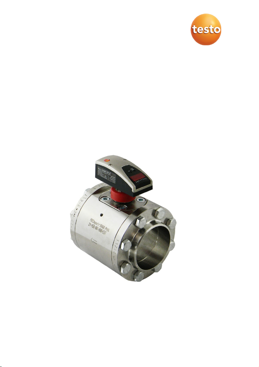
testo 6446 compressed air meter
Instruction manual
Page 2

Page 3

Contents
1 GENERAL INFORMATION ........................................................................... 5
1.1 Incoming goods inspection, transportation and storage ....................................... 5
2 SAFETY PRECAUTIONS .............................................................................. 6
2.1 Intended use ......................................................................................................... 6
2.2 Installation, commissioning and operation ............................................................ 7
2.3 Exclusion of liability ............................................................................................... 8
3 DESIGN AND FUNCTION ............................................................................. 9
3.1 Electric sensor unit .............................................................................................. 10
3.2 Compac stainless steel sealing cone .................................................................. 12
3.3 Compac welding neck flange (V flange) steel ..................................................... 12
3.4 Dummy plugs included as standard .................................................................... 13
3.5 Measuring station ................................................................................................ 14
3.6 ISO calibration points .......................................................................................... 14
4 TECHNICAL DATA ..................................................................................... 15
4.1 Thermal mass flow sensor .................................................................................. 15
4.2 Accessories ......................................................................................................... 16
4.2.1 Connecting cable with electric isolation .................................................... 16
4.2.2 Replacement sensor ................................................................................. 16
4.2.3 Calibration options .................................................................................... 16
5 INSTALLATION ........................................................................................... 17
5.1 Determining the installation point ........................................................................ 17
5.2 Length measurements of the compressed air meter .......................................... 18
5.3 Installation position ............................................................................................. 19
5.4 Required measuring section ............................................................................... 20
5.5 Direction of flow .................................................................................................. 20
5.6 Installation of the compressed air meter ............................................................. 21
5.6.1 Installation of the measuring station ......................................................... 21
5.6.2 Installing the sensor in the measuring station .......................................... 22
22
5.7 Sensor replacement ............................................................................................ 23
5.8 Electrical connection ........................................................................................... 24
5.8.1 4-wire pin assignment ............................................................................... 24
5.8.2 5-wire pin assignment (accessory) ........................................................... 25
Page 4

Contents
6 OPERATION ............................................................................................... 26
6.1 Operation and display elements ......................................................................... 26
6.2 Types of operation .............................................................................................. 28
6.2.1 Run mode 28
6.2.2 Display mode 28
6.2.3 Programming mode – parameter configuration ........................................ 28
7 MENU .......................................................................................................... 29
7.1 Menu overview ................................................................................................... 29
7.2 Menu explanation ............................................................................................... 30
8 PROGRAMMING AND PARAMETRISATION ............................................ 31
8.1 Programming ...................................................................................................... 31
8.2 Parametrising scenarios ..................................................................................... 33
8.2.1 Settings for flow monitoring ...................................................................... 33
8.2.2 Settings for consumption quantity monitoring .......................................... 34
8.2.3 Settings for temperature monitoring ......................................................... 36
8.2.3.1 Configuring the analogue value for temperature ...................................... 36
8.2.4 User settings (optional) ............................................................................ 37
8.2.5 Service functions ...................................................................................... 39
8.2.6 Pulse setting 40
8.2.7 Hysteresis function ................................................................................... 41
8.2.8 Window function ....................................................................................... 41
8.2.9 Scaling the measuring range .................................................................... 42
9 REPAIR ....................................................................................................... 43
9.1 Error messages .................................................................................................. 43
9.2 Cleaning the sensor ............................................................................................ 43
9.2.1 Cleaning agents ....................................................................................... 43
9.3 Recalibration ....................................................................................................... 44
10 TROUBLESHOOTING ................................................................................ 45
10.1 Replacing damaged parts ................................................................................... 45
10.2 Replacing O-rings and sealing rings ................................................................... 45
10.3 Return shipment ................................................................................................. 45
10.4 Disposal .............................................................................................................. 45
Page 5

1
GENERAL INFORMATION
1.1 Incoming goods inspection, transportation and storage
• Take note of undamaged packaging!
Communicate damages to the packaging to your supplier. Retain the
damaged packaging until the matter is settled.
• Make sure there is no damaged contents!
Communicate damages to the contents to your supplier. Retain the
damaged goods until the matter is settled.
• Check the scope of delivery for completeness by referring to the
shipping documents and your order.
• The instrument is to be packaged for storage and transport in a way
that protects it from impacts and moisture. The original packaging
offers optimum protection. The permissible ambient conditions are also to
be observed ( see 4 Technical data).
• If you have any questions, please contact your supplier or their
sales office.
5
Page 6
2
SAFETY PRECAUTIONS
Read this instruction manual before commissioning the
compressed air meter. Store this instruction manual in a location
that is accessible for all users at all times.
2.1 Intended use
The compressed air meter is intended exclusively for use in pipe
systems for working compressed air, provided that the calibration
certificate does not explicitly allow use with other gases.
WARNING
ATTENTION
The structural design allows for operation in pressurised
systems up to PN 16 (DN 65 bis DN 200) and PN 14 (DN 250)
Any use other than that described will compromise the
safety of persons and the entire measuring system and is
therefore not permitted.
The manufacturer shall accept no liability for damages that
occur as a result of improper or inappropriate use or
installation.
To prevent damage to the instruments or health risks occurring
the measuring units must never be manipulated with tools
unless expressly defined in this instruction manual.
The compressed air meter may only be operated under the ambient
conditions specified in the technical data. Otherwise, inaccurate
measurements will occur and instrument malfunctions cannot be ruled out.
To ensure the safety of the user and the functionality of the instruments,
the commissioning steps, checks and maintenance work recommended by
the manufacturer are to be complied with and carried out.
These instructions do not contain complete detailed information for the
sake of transparency. Should you require further information or should a
specific problem occur that is not comprehensively handled in the
instructions, you can request the required information directly from the
manufacturer.
6
Page 7

2.2 Installation, commissioning and operation
The compressed air meter was built and tested reliably according to
state-of-the-art technology and left the factory in an appropriately safe
condition.
As the user, you are responsible for compliance with all valid
safety regulations, including:
• Installation specifications
• Local standards and regulations.
The manufacturer has undertaken all necessary measures to ensure
safe operation. The user must ensure that the instruments are set up
and installed in such a way that their safe use is not affected.
This instruction manual contains information and warnings that must
be followed by the user in order to ensure safe operation.
• Installation, commissioning, operation and maintenance of the
measuring unit may only be performed by trained, authorised
personnel.
The personnel must be authorised for the specified tasks by the
system operator.
• The authorised personnel must have read and understood this
instruction manual and comply with the instructions set out in it.
• Check all connections for correctness before commissioning the
complete measuring station.
• Do not commission damaged products and keep these from being
inadvertently commissioned. Mark the damaged products as
defective.
• Faults at the measuring point are only to be corrected by authorised
and specially trained personnel.
• If faults cannot be corrected, the products must be taken out of
operation and be safeguarded from inadvertent commissioning.
• Repairs that are not described in this instruction manual may only be
carried out directly by the manufacturer or by the service organisation.
7
Page 8

2.3 Exclusion of liability
Liability of the manufacturer and its vicarious agents shall exist only in the
event of deliberate acts or gross negligence. The extent of liability shall be
limited to the value of the respective order placed with the manufacturer.
The manufacturer shall accept no liability for damages that occur due to
non-observance of the safety instructions or non-compliance with the
instruction manual or the operating conditions. Consequential damages
are excluded from the liability.
Use the components only in the supplied combination.
Due to the design, they are not necessarily compatible
Note
with older compressed air meters.
8
Page 9

3 DESIGN AND FUNCTION
Overview of components
1 Sensor unit 2 Straight pin as alignment aid
3 Hexagon socket head screw M 10 4 Dummy plug
5 Dummy plug holder both sides 6 Direction of flow arrow
7 Measuring station 8 Brass sealing plug
9 Hexagon screw depending on DN 10 Viton O-rings
11 Compac steel welding
neck flange
12 Compac stainless steel sealing
cone
9
Page 10

The equipment is supplied loosely pre-assembled in 2 parts:
sensor and station. Also included in the scope of delivery:
•
Calibration certificate in compliance with ISO/IEC 17025
3.1 Electric sensor unit
The sensor records the standard volumetric flow of the working
compressed air according to the calorimetric measurement principle.
The standard volumetric flow is calculated on the basis of DIN ISO 2533
(1013.25 mbar, 15 °C and 0% relative humidity), unless otherwise stated
on the calibration certificate. The relevant unit is Nm³/h or Nl/min.
Observe the general operating conditions for compressed air
systems. The air quality of the working compressed air influences the
measuring accuracy as follows:
Quality classes according to
ISO 8573-1 particle/humidity/oil
1-4-1
3-4-4
Measuring signals
Measurement errors
± (3% of reading + 0.3% of final
value of measuring range)
± (6% of reading, + 0.6% of final
value of measuring range)
The instrument shows the current process values on a display. It
generates 2 output signals according to the parametrization.
•
Current flow rate
•
Current consumption quantity (pulse output module and totaliser)
Display
•
Current volume flow in Nm³/h or Nl/min
•
Current consumption quantity in Nm³
•
Current average speed in Nm/s
•
Current media temperature in °C
•
Switching states of the respective outputs
10
Page 11
Sensor output 1
•
Switch signal as the limit value for volume flow or flow velocity, hysteresis or
window function as N/O or N/C contact.
•
Quantity monitoring using the preset counter.
Sensor output 2
•
Switch signal as the limit value for volume flow, flow velocity or
temperature, hysteresis or window function as N/O or N/C contact.
•
Analogue signal (4-20 mA) for volume flow, flow velocity or temperature.
Relative measuring range (%)
Measuring range
Recording/
display range
0.33% (0.4%) - 100% 0% to 120%
The absolute measuring range depends on the nominal width (see
following table).
Absolute measuring range
The compressed air meter may be used to measure the
volume flow of working compressed air with up to 16 bar
(DN 65 to DN 200) or 14 bar (DN 250) overpressure.
WARNING
Nominal width Measuring range Recording/
display range
DN 65 6.7-2,000 m³/h 0.11-2,400 m³/h
DN 80 9.2-2,750 m³/h 0.15-3,300 m³/h
DN 100 15-4,400 m³/h 0.24-5,280 m³/h
DN 125 23-7,000 m³/h 0.39-8,400 m³/h
11
Page 12

Nominal width Measuring range Recording/
display range
DN 150 33-10,000 m³/h 0.55-12,000 m³/h
DN 200 58-17,500 m³/h 0.97-21,000 m³/h
DN 250 92-27,500 m³/h 1.53-33,000 m³/h
Specifications according to DIN ISO 2533 (15 °C, 1013 mbar and 0%
rel. humidity).
3.2 Compac stainless steel sealing cone
The Compac sealing cone makes up the intersection between the
measuring station and sensor. Please note the following design details for
correct positioning of the components after welding in the pipeline
according to the direction of flow: The straight pin of the measuring station
engages in the one-sided bore of the Compac sealing cone.
This is designed with a slot that receives the sensor pin in the downstream
direction of flow.
3.3 Compac welding neck flange (V flange) steel
The connection between the measuring point interface and the pipe
system is made by the Compac welding neck flanges. These seal twice –
both metal-wise and against an O-ring made of Viton in a circumferential
groove in the measuring station. The advantages of these flanges in
comparison to standard DIN flanges with flat seals are the significantly
smaller construction volume and thus material volume and weight, lower
bolt tightening forces and the prevention of overstraining of the seal (with
regard to deformation and compression) – with higher density efficiency
and leakage reliability. Slight scratches in the contact surfaces are
tolerated without loss of function due to the high compressive force.
Example: DN 250 at PN 100
•
Compac flange weight 15 kg
• Previous DIN flange weight 81 kg
12
To avoid a mixed seam in the welded joint to the pipeline,
make sure that the Compac flanges are made of steel or
Note
An alternative to the welding neck flange (V flange) is to fit a Compac threaded
flange (G flange).
stainless steel according to the pipeline.
Page 13
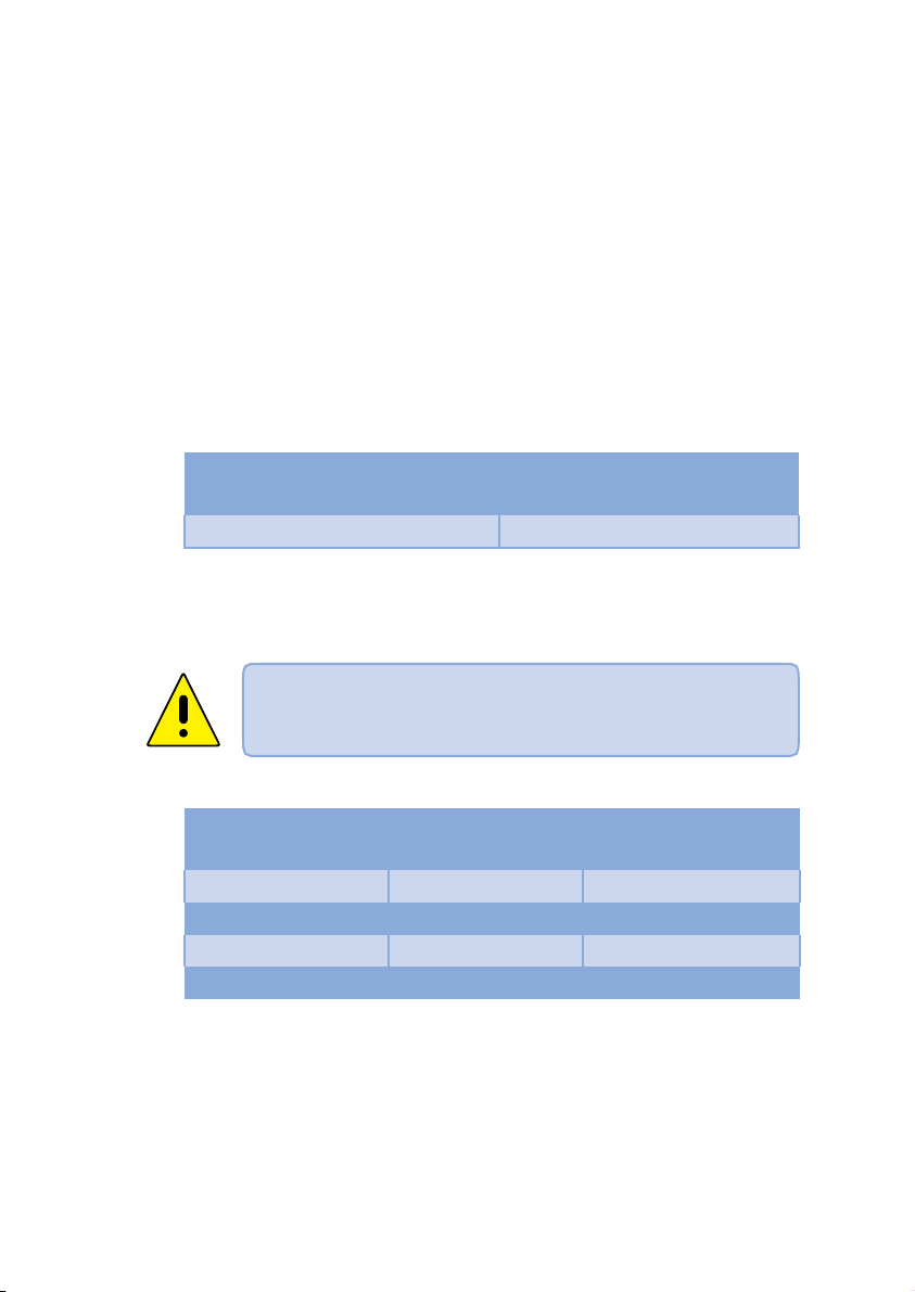
Sealing principle of the Compac flange
P
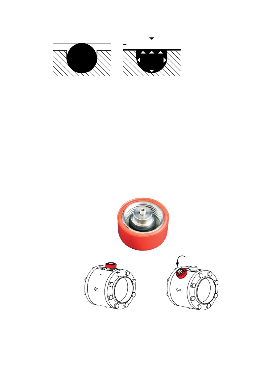
3.4 Dummy plugs
The dummy plug is made of stainless steel and has a bright red plastic
protective cap to stop it unintentionally loosening.
It secures the measuring point interface while the sensor is uninstalled,
e.g. when changing the sensor for recalibration. For this purpose, it is
screwed onto the sealing cone (Fig. 1) when the line is
depressurized.
The dummy plug seals both metal-wise and redundantly via an O-ring.
A significant advantage over simple dummy plugs is that the trapped
compressed air can escape safely under pressure during
(unintentional) disassembly. When turning the union nut, enough
thread turns remain to prevent it "shooting off". If the sensor is
installed, the dummy plug is stored near the device in one of the
holders (tapped bore) – as shown in Figure 2.
1
included as standard
2
13
Page 14

3.5 Measuring station
The measuring station with Compac welding neck flanges is used to
precision-mount the electronic volume flow sensor. The measuring station
is welded into the pipelines with the Compac welding neck flanges in line
with the flow direction (see engraved direction arrow). The nominal width
of the measuring station and welding neck flange must match the
nominal pipe width ( see 3). To prevent a mixed seam during welding,
the material of the parts must also be the same.
The compressed air meter is designed for nominal pipe widths from
DN 65 to DN 250.
3.6 ISO calibration points
The compressed air meter is supplied calibrated to its nominal width.
A minimum of six measuring points are parametrised with specified
nominal widths, standard temperatures and pressures, then moved to the
test stand where the standard volume is tested. The calibration certificate
in compliance with ISO/IEC 17025 is included in the scope of delivery.
14
Page 15

4 TECHNICAL DATA
4.1 Thermal mass flow sensor
The thermal mass flow sensor for the compressed air volume flow
measurement is independent of the process pressure and the media
temperature.
Sensor Thermal glass-coated ceramic sensor
Media Compressed air
Accuracy For compressed air quality classes (ISO 8573:
particles to humidity to oil) 1:4:1: ±3% of
reading, ±0.3% of final value for compressed air
quality classes (ISO 8573) 3:4:4: ±6% of
reading, ±0,6% of final value
Temperature monitoring ±2 °C
Reproducibility ±1.5% of reading
Display, operation 4-digit, alphanumerical display, two operating
buttons, user menu, operating menu, 5 x green
LED (measurement units), 1 x green LED
(function display 103), 2 x yellow LED (switching
status)
Display units* Nl/min, Nm³/h, Nm/s, Nm³, °C
Measuring dynamics 1:300
Response time < 0.1 s
Pressure-tight up to 16 bar (DN 250 to 14 bar)
Media temperature 0 to + 60 °C (rel. humidity max. 90%)
Perm. ambient temp. 0 to + 60 °C
Perm. storage temp. -20 to + 85 °C
Media contact V2A (1.4301) or galvanised steel, glass-coated
ceramic, PEEK, polyester, Viton, anodised
aluminium
Housing materials PBT-GF 20, PC (APEC), Makrolon, V2A
(1.4301) or galvanised steel, Viton
Protection class IP65 / III
Electrical connection M12 x 1 connector, can be loaded to 250 mA,
short-circuit-proof
Power supply 19 to 30 VDC, voltage supply < 100 mA
Readiness delay 1 s
Based on the small size, the sensor only has a small contact
surface. The pressure loss is thus negligible (typically
1 mbar).
Note
* The measurement, display and adjustment ranges are related to the
standard volume flow according to DIN ISO 2533 (15 °C, 1013 mbar and 0%
rel. humidity) if not otherwise stated in the calibration protocol of the sensor.
15
Page 16

Output signals
Analog output 4-20 mA, measuring range scaleable
max. load 500 Ω pulse output
DN 65 - DN 80: 1 pulse/1 Nm³
DN 100 – DN 250: 1 pulse/10 Nm³
Current carrying capacity 2 x 250 mA, short-circuit-proof, protected against
polarity reversal, overload-proof
EMC
IEC 1000/4/2 ESD 4/8 kV
IEC 1000/4/3 HF radiated 10 V/m
IEC 1000/4/4 burst 2 kV
IEC 1000/4/6 HF grid-bound 10 V
4.2 Accessories
4.2.1 Connecting cable with electric isolation
A connecting cable with an electrical isolator integrated into the connector
is available as an accessory. The cable is 5 metres long and is used for
the galvanic isolation of the sensor output to the electronics to which it is
attached. The cable is delivered with an appropriate connector for the
mass flow sensor on one side and with open cable ends on the other side.
4.2.2 Replacement sensor
The replacement sensor serves as a replacement in case of damage to or
loss of the original mass flow sensor.
When ordering a new sensor, please indicate the certificate
number of the old sensor in order to take account of
Note
customer-specific measuring conditions directly during
calibration.
4.2.3 Calibration options
• ISO certificate
An ISO certificate from the manufacturer documents six measuring points
including the measuring conditions.
16
Page 17

5
INSTALLATION
Installation may only be carried out by authorised, qualified
staff, e.g. pipeline engineers. Please observe the relevant
national regulations.
WARNING
WARNING
The electrical connections are to be performed by a
qualified electrician.
To install and remove the sensor the line must be
depressurized. Ensure that the line section cannot be
inadvertently used (lockout-tagout).
5.1 Determining the installation point
Please always observe the technical data see 4.1). The place of
installation is to meet the following criteria:
• Medium does not condense at the place of installation, i.e. measuring
location only behind a suitable compressed air dryer, which ensures
an appropriate pressure dew point. Otherwise the specified measuring
accuracy cannot be guaranteed.
• Ambient temperature of maximum + 60 °C (note any potential thermal
radiation).
• Take account of the inflow and outflow section ( see 5.4).
• Take account of the direction of flow ( see 5.5).
• Well accessible with low vibration.
• A min. 200 mm space is needed to remove the sensor.
17
Page 18

5.2 Length measurements of the compressed air meter
L
18
Inch DN L
2½" 65 148 125 70.3 2.9 184 8 13 106
3" 80 160 141 82.5 3.2 198 8 13 118
4" 100 160 165 107.1 3.6 223 8 13 144
5" 125 172 205 131.7 4 255 12 13 168
6" 150 180 235 159.3 4.5 284 8 17 200
8" 200 180 290 207.3 5.9 336 12 17 252
10" 250 196 355 260.4 6.3 396 12 21 315
mm
Ø D1
mm
Ø D2
mm S mm
H1
mm
N SL
mm
LK
mm
Page 19

5.3 Installation position
Do not install the sensor in the crossed-out installation positions
shown in the following graphic in point 6. Otherwise, in the event of a
limited flow rate, the specified accuracy cannot be maintained.
Diagrams:
1.
2.
3.
4.
5.
6.
The arrow shows the direction of flow for the medium.
1: Vertical installation position, direction of flow horizontally to the left,
probe downwards
2: Horizontal installation position, direction of flow vertically downwards,
probe to the rear
3: Horizontal installation position, direction of flow horizontally to the rear,
probe to the left (heated sensor element upwards)
4: Vertical installation position, direction of flow horizontally to the right,
probe upwards
5: Horizontal installation position, direction of flow vertically upwards, probe
to the rear
Horizontal installation position, direction of flow horizontally to the rear,
6:
probe to the right (heated sensor element downwards, problems
possible at low flow rates)
19
Page 20

5.4 Required measuring section
Take account of the required inflow and outflow section in
order to achieve the specified measuring accuracy. The
inflow section refers to the pipeline length upstream of the
Note
Total measurement section = inflow section + outflow section
Outflow section = 5 x D
Inflow route = 15 x D + B
D = pipe diameter [mm]
B = additional calming section
compressed air meter and the outflow section to the
pipeline length downstream of the compressed air meter,
as seen in the direction of flow for the medium.
Changes to the
pipe diameter
90° elbow B = 5 x pipe diameter
Two 90° elbows, one level
Two 90° elbows, two levels
Valve, slider B = 35 x pipe diameter
B = 5 x pipe diameter
B = 10 x pipe diameter
B = 15 x pipe diameter
5.5 Direction of flow
Always take the direction of flow into account when
installing the measuring station. This is indicated by the
Note
20
arrow engraved on the side of the measuring station. The
arrow points in the direction that the medium flows in the
pipeline.
Page 21

5.6 Installation of the compressed air meter
To avoid a mixed seam in the welded joint to the pipeline,
make sure that the Compac flanges are made of steel or
Note
WARNING
WARNING
5.6.1 Installation of the measuring station
stainless steel according to the pipeline.
To install and remove the compressed air meter the line
must be depressurized. Ensure that the line section cannot
be inadvertently used (lockout-tagout).
A stable stepladder is required for all assembly work
carried out up to 2.5 metres off the floor (height of the
pipe). A working platform must be provided for work at
greater heights. If the measuring point cannot be accessed by
a platform, then scaffolding or other equipment must be
used to provide a safe working platform.
1. Depressurize the pipe section at the installation point and secure it
against accidental reconnection (lockout-tagout).
2. Weld the Compac welding neck flange to the existing pipeline with no
torsion, taking national regulations into account, to achieve
optimal tightness.
Make sure that the measuring station is installed in the
direction of flow – see arrow. Otherwise, there may be
Note
sensor measuring inaccuracies.
21
Page 22

3. Screw the measuring station between the flanges according to the
direction of flow. Fix the screws in diagonal order for even force
distribution.
5.6.2 Installing the sensor in the measuring station
Make sure that the pipeline is depressurized before
installing the sensor. Make sure that the Compac sealing
cone is always closed either with a sensor or a dummy
plug.
WARNING
1. To install the sensor unscrew the dummy plug from the sealing cone
and temporarily store it in the holder on the side of the measuring
station.
2.
Remove the red protective transportation cap from the tip of the sensor
and keep it for the next time you remove the sensor.
22
3. Install the sensor in the sealing cone of the measuring station. Take
notice of the correct installation position of the sensor. Due to the
design, the sensor can only be screwed onto the sealing cone in one
direction (bolt/groove principle). The head of the sensor, i.e. the
display, points in the direction of the inflow. If this is not the case, the
measuring station has to be turned between the flanges.
Page 23

4. Fix the sensor to the measuring station with the union nut and without
tools.
5. The mechanical installation of the compressed air meter is now
complete.
5.7 Sensor replacement
The removal of the mounted sensor may be necessary for maintenance,
cleaning and calibration purposes.
Never remove the sensor or the dummy plug from the
sealing cone when the line is under pressure – this may be
WARNING
1. Switch off the pressure in the line and check to make sure no
2. Remove the electrical connecting cable by unscrewing the connector
3. Remove the sensor without tools from the measuring station pulling it
4. Mount the dummy plug ( 3.4) on the sealing cone.
life-threatening!
pressure is applied! Secure the system to ensure it cannot be
inadvertently switched on!
from the sensor by hand. Protect the connector from contamination
and moisture.
up and out vertically.
5. Protect the sensor tip with the red protective transportation cap.
23
Page 24

5.8 Electrical connection
Disconnect the system from the power supply when connecting.
The instrument may only be installed by a qualified
electrician. Follow the national and international regulations
regarding the installation of electrical engineering systems. The
voltage supply is to be laid out in accordance with EN50178,
WARNING
Note
5.8.1 4-wire pin assignment
If you use the standard connection, the following pin assignment applies to
the connecting cable or the pin assignment directly on the sensor.
SELV, and PELV. To meet the "limited voltage" requirements
according to UL 508, the instrument must be supplied from a
galvanically isolated source and protected against shortcircuits by means of an overcurrent device.
If you are connecting the sensor directly or using a 4-wire
connecting cable, proceed as set out in 5.8.1.
If you are using the optionally available 5-wire connecting cable
with potential-free pulse output ( see 4.2.2), proceed as set
out in 5.8.2 when connecting the sensor.
24
BN L+
2
1
3
4
WH OUT2/InD
BK OUT1
BU L
Pin no. Wire colour Assignment
1 Brown +L (19-30 V DC)
2 White
OUT2
/InD
3 Blue 0 V DC (GND)
4 Black OUT1
Page 25

5.8.1.1 1 x pulse output, 1 x analog output (condition on delivery)
The OUT1 output is used as a PNP signal output (pulse) and the OUT2
output is used as an analog output. This is the configuration in which the
sensors are delivered.
Pin = designation (wire colour)
1= BN (brown)
2= WH (white)
3 = BU (blue)
4 = BK (black)
5.8.1.1 2 x pulse output
Both of the available OUT1and OUT2 outputs are each used as a PNP
signal output (pulse).
5.8.2 5-wire pin assignment (accessory)
If the optional connecting cable for electrical isolation is used ( see
4.2.2), then the following assignments apply.
Pin no. Wire colour Assignment
1 Brown +L (19 to 30 V DC) sensor supply
2 Pink + potential-free pulse output (collector) OUT1
3 White - potential-free pulse output (emitter) OUT1
4 Green OUT2
5 Black 0 V DC (GND)
25
Page 26

The potential-free pulse output OUT1 is specified for this connecting
cable as follows:
Line type LiYCY
Length 5 m
Switching capacity 500 mA
Max. switching voltage 36 V
Min. switching voltage 5 V
Switch contact resistance 0.21 Ω
Insulation voltage 5.3 kV
Protected against polarity
reversal
6 OPERATION
Thermal mass flow sensor
Familiarise yourself with the operation and programming of the sensor.
The sensor is calibrated ex factory and provided with default settings for
each nominal width.
Yes
6.1 Operation and display elements
The following illustration shows the control and display unit of the sensor
from above.
1 2 3 4 5 6
/h
3
Nm
Nm/s
Nm
°C
26
9
10
3
Nl/min
Mode/Enter Set
3
10
7 8
SP2
SP1
11
Page 27

Type Description
Indicator LEDs
①
to
LED
⑧
LED
LED
LED
LED
LED and
LED and
flashing
LED
LED
LED
LED
Four-digit
⑨
alphanumeric
display
flashing
SP2
SP1
Illuminated LED = display unit set
Current flow rate (Nl/min)
When the LED lights up, displayed value x 1000
Current flow rate (Nm3/h)
When the LED lights up, displayed value x 1000
Current flow velocity (Nm/s)
Current consumption quantity since last reset (Nm3)
Consumption quantity before the last reset in (Nm3)
Current consumption quantity since last reset in 103 (Nm3)
(Values > 9999 are displayed in 103 exponential mode)
Consumption quantity before last reset in 103 (Nm3)
(Values > 9999 are displayed in 103 exponential mode)
= 103 exponential mode
Current media temperature in °C
Switching status of the respective output (LED also
indicates the status of the input during an active external
reset)
Switching status of the respective ouput
Display of the current volume flow (for setting
Uni = Lmin or nm3h and SELd = FLOW)
Display of the current flow velocity (for setting Uni =
nmS and SELd = FLOW)
Display of the meter reading (for setting SELd = TOTL)
Display of the current media temperature (for setting
SELd = TEMP)
Display of the parameters and parameter values
⑩
⑪
Button
Mode/Enter
Programming
button
Set
Selection of the parameters and confirmation of the
parameter values
Setting the parameter values
Changing the display unit in run mode
27
Page 28

6.2 Types of operation
6.2.1 Run mode
After switching on the supply voltage, the instrument is in run mode.
It carries out its measurement and evaluation functions and provides
output signals according to the set parameters.
The display shows the current measurement values and the yellow LEDs
show the switch status of the outputs.
The display unit may be changed temporarily. For this purpose, press the
Set button briefly. After 15 seconds, the instrument returns to the display
unit that was set in the Uni menu item.
The totaliser (consumption quantity counter) stores interim values every
10 minutes as well as the amount of time elapsed of the automatic reset.
After a drop in voltage, this value is available as the current status of the
totaliser (the possible loss of data can amount to a maximum of
10 minutes).
6.2.2 Display mode
Display of the parameters and set parameter values.
The instrument is switched to display mode by briefly pressing
Mode/Enter.
Internally, it remains operational.
The set parameter values can be read independently of this:
To scroll through the parameters briefly press the Mode/Enter button.
The corresponding parameter value is displayed for approximately
15 seconds by briefly pressing the Set button. After a further
15 seconds, the instrument returns to run mode.
6.2.3 Programming mode – parameter configuration
28
The instrument is switched to programming mode if a parameter is
selected and the Set button is pressed for longer than 5 seconds (the
parameter value flashes, then is continuously increased). Internally, the
instrument also remains operational.
It continues to carry out its monitoring functions with the existing
parameters until the change is completed.
You can change the parameter value using the Set button and confirm
by pressing the Mode/Enter button.
The instrument returns to measurement mode if no buttons are pressed for
15 seconds afterwards.
Page 29

7
MENU
7.1 Menu overview
In the menu overview, indicates the
Mode
button on the sensor.
Nl/min
Nm3/h
S
M
M
M
M
M
M
M
M
M
M
M
15s
S
S
M
S
S
S
S
S
S
M
M
S
M
S
M
M
M
M
M
S
M
S
M
M
Nm/s
15s
S
M
Set
button and the
3
Nm
S
15s
Nm3*
S
S
15s
M
M
M
M
M
M
M
M
M
M
M
M
M
M
S
°C
15s
S
M
S
M
S
M
S
M
S
M
S
M
S
M
S
M
S
M
S
M
S
M
S
M
S
M
S
M
(Nm³)* = volume flow amount before the last reset
The parameter values given in digits represent factory settings or
random examples.
29
Page 30

A
7.2 Menu explanation
SP1/rP1
Switching point or Return switching point Upper/lower limit
value for flow rate
ImPS
Pulse value
ImPR Repeat pulse yes = active = pulse output or no = not active =
preset counter function
OU1 Initial function for OUT1 (flow rate or consumption quantity):
- Switching signal for limit values: Hysteresis function Hno and
Hnc or window function Fno and Fnc
o = normally open = N/O contact; c = normally closed = N/C
contact
- Pulse or switching signal for quantity counter
OU2 Initial function for OUT2 (flow rate or temperature):
o Switching signal for limit values: Hysteresis function or
window function, N/O contact or N/C contact respectively
o Analogue signal: 4-20 mA [I]
Alternatively: Configure OUT2 (pin 2) as an input for an
external reset signal: Setting: OU2 = InD
SP2/rP2 Switch point or return switch point
Upper/lower limit value for flow rate or temperature
SP2 and rP2 are only active when OU2 = Hno, Hnc, Fno or Fnc
ASP/
EP
DIn2
Analogue starting value/Analogue end value for flow rate or
temperature
Configuration of the input (pin 2) for counter reset
EF Extended Functions/opens menu level 2
HI/LO
Maximum value memory/minimum value memory for flow rate
FOU1 Behaviour of output 1 in the event of an internal error
FOU2 Behaviour of output 2 in the event of an internal error
dAP
rTo
diS
Uni
Measuring value damping/damping constant in seconds
Counter reset: manual reset/time-controlled reset
Updating rate and orientation of display
Standard unit of measurement for flow rate: Nl/min, Nm³/h
or Nm/s
SELd
Standard display measurement parameter:
Flow value, meter reading or media temperature
30
Page 31

SEL2 Standard measurement parameter for evaluation using
OUT2:
1. Limit value signal or analogue signal for flow rate
2. Limit value signal or analogue signal for temperature
rEF.P
rEF.T
LFC Low flow cut-off
rES
Standard pressure measurement and display values refer to for
the flow rate
Standard temperature measurement and display values refer to
for flow rate
Reset – reset to factory settings
8 PROGRAMMING AND
PARAMETRISATION
8.1 Programming
Each parameter setting requires 3 steps: select
parameter – set value – confirm
Press the Mode/Enter button until the
required parameter appears on the
display.
Press and hold the Set button.
The current parameter value flashes
for 5 seconds. It is then increased*
(in increments by pressing once or
continuously by pressing and holding
the button).
Press the Mode/Enter button briefly (=
confirmation). The parameter is
displayed again and the new parameter
value applies.
Changing further parameters: Start again with step 1.
Ending programming: Wait for 15 seconds or press the
Mode/Enter button until the current
measuring value appears again.
31
Page 32

* To reduce the value:
Allow the display to run through to the maximum setting value. After this,
the run-through starts again from the minimum setting value. Set the
display unit Uni before you set the values for the SPx, rPx, ASP and AEP
parameters. In this way, rounding up/down errors are avoided during the
internal conversion into other units and the exact values required are
provided.
Condition at delivery: Uni = nm3h.
If no button is pressed for 15 seconds during the configuration process,
the instrument returns to run mode with unchanged values.
Switching from menu level 1 to level 2
Press the Mode/Enter button until
EF is displayed.
Briefly press Set.
The first parameter of the submenu is
displayed: HI.
Locking – unlocking
To prevent unintentional wrong entries the instrument can be electronically
locked. Condition at delivery: Not locked.
32
Make sure that the instrument is in
normal work mode.
Press Mode/Enter +
Set for
10 seconds.
is displayed.
Loc
During operation, Loc is briefly
displayed, if you try to change the
parameter values.
To unlock: Press for 10 seconds
Mode/Enter +
Set. uLoc is displayed.
Page 33

8.2 Parametrising scenarios
8.2.1 Settings for flow monitoring
8.2.1.1 Configuring limit monitoring with OUT1
Uni
OU1
SP1
rP1
8.2.1.2 Configuring limit monitoring with OUT2
Uni
SEL2
FLOW
OU2
SP2
rP2
select and specify unit of measurement ( see 8.2.4).
select and set the switching function.
Hno = hysteresis function/NO contact
Hnc = hysteresis function/NC contact
Fno = window function/NO contact
Fnc = window function/NC contact
select and set value with which the output switches.
select and set value with which the output switches back.
select and specify unit of measurement ( see 8.2.4).
select and set.
select and set the switching function.
Hno
= hysteresis function/NO contact
Hnc
= hysteresis function/NC contact
Fno
= window function/NO contact
Fnc
= window function/NC contact
select and set value with which the output switches.
select and set value with which the output switches back.
33
Page 34

8.2.1.3 Configuring the analogue value for flow rate
Uni
SEL2
FLOW
OU2
ASP
select and specify unit of measurement ( see 8.2.4).
select and
set.
select and set the function.
I
= flow-proportionate current signal (4 to 20 mA)
select and set value with which the
minimum value
is output.
AEP
select and set value with which the
maximum value
is output.
8.2.2 Settings for consumption quantity monitoring
8.2.2.1 Configuring quantity monitoring through pulse output
OU1
ImP
ImPS
select and
set.
select and set the flow volume with which 1 pulse is
emitted each time ( see 8.2.6).
ImPR
YES
select and
set.
> Pulse repetition is active.
each time the value set in
Output 1
ImPS
is reached.
emits a counting pulse
8.2.2.2 Configuring the quantity monitoring using the preset counter
OU1
ImP
ImPS
select and
set.
select and set the flow volume with which
output 1
is
activated ( see 8.2.6).
34
ImPR
NO
select and
set.
> Pulse repetition is not active. The output switches ON when
the value set in
ImPS
is reached. It remains switched until the
counter is reset.
Page 35

8.2.2.3 Configuring program-controlled reset
rTo
Set
select; continue with a) or
a)
reset counter manually
Press until
rES.T
is displayed, then briefly press
b)
Set
Set
b)
enter value for time-controlled reset
Press until the required value is displayed (intervals of 1
hour to 8 weeks), then briefly press
Press until
rES.T
is displayed, then briefly press
Mode/Enter
8.2.2.4 Deactivating counter reset
rTo
OFF
select and
set.
The counter is reset only after overrun (= factory setting).
Overrun: the counter is reset to 0 after the maximum value
(9 999 999 Nm³).
8.2.2.5 Configuring counter reset using an external signal
OU2
InD
Din2
select and
set.
select and set the reset signal.
HIGH
= reset for high signal
LOW
= reset for low signal
+EDG
= reset for rising flank
-EDG
= reset for falling flank
Mode/Enter
.
Mode/Enter
.
.
LED 7 ( see 6.1 Controls and indicators) also indicates the input status during
an active external reset.
35
Page 36

8.2.3 Settings for temperature monitoring
8.2.3.1 Configuring limit monitoring with OUT2
SEL2
TEMP
select and
set.
OU2 select and set the switching function.
Hno = hysteresis function/NO contact
Hnc = hysteresis function/NC contact
Fno = window function/NO contact
Fnc = window function/NC contact
SP2 select and set value with which the output switches.
rP2 select and set value with which the output switches back.
8.2.3.1 Configuring the analogue value for temperature
SEL2
TEMP
OU2 select and set the function.
ASP
AEP
select and
set.
I = temperature-proportionate current signal (4 to 20 mA)
select and set value with which the minimum value is output.
select and set value with which the maximum value is output.
36
Page 37

8.2.4 User settings (optional)
8.2.4.1 Specifying the standard unit of measurement for flow rate
Uni select and specify unit of measurement.
Lmin = flow volume per standard litre/minute
nm3h = flow volume per standard cubic metre/hour
nmS = flow velocity per standard metre/second
The setting only affects the flow rate value.
Set the display unit before you set the values for the SPx, rPx,
ASP and AEP parameters. In this way, rounding up/down errors
are avoided during the internal conversion into other units and
the exact values required are provided.
8.2.4.2 Configuring the standard display
SELd select and specify standard measurement parameter.
FLOW = display shows current flow rate value in standard unit
of measurement
TOTL = display shows current meter reading in Nm3 or
1000 Nm
TEMP = display shows current media temperature in °C
3
diS select and specify updating rate and orientation of display.
d1 = reading update every 50 ms
d2 = reading update every 200 ms
d3 = reading update every 600 ms
rd1, rd2, rd3 = display as with d1, d2, d3; rotated by 180°
OFF = display is off in working mode; by pressing the button,
the process value appears for 15 seconds.
8.2.4.3 Setting measuring value damping
dAP select and set damping constant in seconds (t value
63%).
37
Page 38

8.2.4.4 Configuring the error characteristics of the outputs
FOU1 select and specify value
On = output 1 switches ON in the event of an
error.
OFF = output 1 switches OFF in the event of
an error.
> With both values – ON and OFF – the meter no longer runs in
the event of an error.
OU = output 1 switches as defined with the parameters
irrespective of any error.
FOU2 select and specify value
On = output 2 switches ON in the event of an error; the
analogue signal goes to the upper end value (22 mA).
OFF = output 2 switches OFF in the event of an error; the
analogue signal goes to the lower end value (3.5 mA).
OU = output 2 switches as defined with the parameters
irrespective of any error. The course of the analogue
signal complies with IEC60947-5-7.
3
13
12
38
)
-30% -20% 0%
100% 120% 130%
Page 39

8.2.4.5 Setting the standard pressure which measurement and display
values refer to for flow rate
rEF.P select and set the required standard pressure. Setting
range: 950 to 1050 hPa in 1 hPa increments.
8.2.4.6 Setting the standard temperature which measurement and display
values refer to for flow rate
rEF.T select and set the required standard temperature. Setting
range: 0 to 25 °C in 1 °C increments.
8.2.4.7 Setting the low flow cut-off
LFC
select and set the limit value.
Setting range: 0.1 to 0.8 Nm³/h in 0.1 Nm³/h increments.
8.2.5 Service functions
8.2.5.1 Reading min./max. values for flow rate
HI
LO
Set
or
select; press
briefly.
HI = maximum value; LO = minimum value
Deleting memory
HI
LO
or
select.
Set press and hold it down until [----] is displayed.
Press Mode/Enter briefly.
It is a good idea to clear the memory as soon as the
instrument is used for the first time under normal working
conditions.
39
Page 40

8.2.5.2 Resetting all parameters to factory setting
After resetting to factory setting, the memory value is zero.
Note
rES
select.
Set press and hold it down until [----] is displayed.
Press Mode/Enter briefly.
It is recommended noting down the individual settings before
carrying out this function.
8.2.6 Pulse setting
ImPS Pulse settings in 7 ranges
ImPS is only active when OU1 = ImP
Display
1 4 0.001 to 9.999 0.001 Nm3 0.001 to 9.999 Nm3
2 4 10.00 to 99.99 LED 10.00 to 99.99 Nm3
3 4 100.0 to 999.9 0.1 Nm3 100.0 to 999.9 Nm3
4 4 1000 to 9999 1 Nm3 1000 to 9999 Nm3
5 4+6 10.00 to 99.99 10 Nm3 10 000 to 99 990 Nm3
6 4+6 100.0 to 999.9 100 Nm3 100 000 to 999 900 Nm3
7 4+6 1000 to 1000 1 000 000 Nm3
Incremental
range
Setting range
40
Page 41

8.2.7 Hysteresis function
- Set OU1 to ImP
- Press Mode/Enter until ImPS is displayed.
Press and hold Set.
> The current numerical value flashes for 5 seconds, then one
of the four digits is active (digit flashes; can be changed).
- Setting the required pulse value:
- First select the required setting range (1, 2, 3, etc.): Press
and hold the Set button until the setting range has the
required value.
- Enter the value from left (first digit) to right (fourth digit).
- Press Mode/ Enter briefly when all 4 digits are set.
If Set is kept pressed down, the display will go through all ranges.
When it reaches the final value, it returns to the first one. Release
Set briefly and begin with the setting again.
The hysteresis keeps the switching status of the
output stable if the flow rate fluctuates around the
nominal value. When the flow rate increases, the
output switches upon reaching the switch point
SPx. If the flow rate decreases again, the output
only switches back when the return switch point
rPx is reached.
The hysteresis is adjustable:
First the switch point is determined, then the
return switch point at the required distance.
8.2.8 Window function
The window function allows a defined OK range
to be monitored. If the flow rate fluctuates
between switch point SPx and return switch point
rPx, the output is switched through (window
function/NO contact) or opened (window
function/NC contact).
The size of the window is adjustable by the
distance between SPx and rPx.
SPx = upper value; rPx = lower value.
41
Page 42

8.2.9 Scaling the measuring range
- With the analog starting point parameter ASP, you determine at which
measuring value the output signal is 4 mA.
- With the analog end point parameter AEP, you determine at which
measuring value the output signal is 20 mA.
- Minimum distance between ASP and AEP = 25% of final value of
measuring range
MEW = final value of measuring range
The output signal is between 4 and 20 mA in the set measuring range.
Further signals are:
• Flow rate above the measuring range: output signal > 20 mA
• Flow rate below the measuring range: output signal between 3.6 and
4 mA.
42
Page 43

9 REPAIR
9.1 Error messages
Display Description
UL
OL Recording range exceeded
SC1 Flashing: short-circuit in switching output 1*
SC2 Flashing: short-circuit in switching output 2*
SC Flashing: short-circuit in both switching outputs*
Err Flashing: Malfunction in probe
* The affected output is switched off as long as the short-circuit lasts.
Measuring value < -20% of final value of measuring
range (temperature)
(Flow rate > 120% of final value of measuring range)
These messages are shown even when the display is off.
Note
9.2 Cleaning the sensor
You must clean the sensor:
• Before each calibration/inspection (at least 1 x per year)
• Regularly during operation.
You can remove the sensor and clean it manually.
9.2.1 Cleaning agents
For cleaning the sensor, use agents containing surfactants (alkaline) or
water-soluble organic solvents (e.g. ethanol).
Isopropanol is recommended for cleaning various contamination, especially
greases and oils.
43
Page 44

Clean the sensor with approved cleaning agents only.
Do not use any chafing (abrasive) cleaning agents. These
can lead to irreparable damages to the sensor.
Carry out a new inspection after the cleaning, as required.
ATTENTION
Note
During cleaning, take care not to mechanically stress the
sensor plates, as they may break, causing irreparable
damage to the sensor. (Rinse the sensor, do not clean
mechanically.)
The sensor is to be cleaned in an ultrasound bath within
2 minutes. For example, a solution of 99% distilled water with
1% EM-404 from EMAG (aluminium and die-cast cleaner)
serves as a cleaning agent. Place the sensor in the mixed
solution – the sensor tip must be completely immersed. Switch
on the ultrasound unit for 2 minutes.
Rinse the sensor tip with pure distilled water and allow it to air
dry.
9.3 Recalibration
Due to contamination (e.g. oil, water and particles) and component drift, an
annual recalibration of the sensor is recommended. Regular calibrations
are essential for cost transparency and correct billing.
44
Page 45

10 TROUBLESHOOTING
10.1 Replacing damaged parts
If faults cannot be corrected, the products must be taken
out of operation and be safeguarded from inadvertent
commissioning. Replace all damaged parts immediately.
Damages to the compressed air meter that affect the pressure
WARNING
To order spare parts please contact our Service team, either by phone on
+49 7653 6810 or email to info@testo.de.
10.2 Replacing O-rings and sealing rings
• Keep the sealing surfaces clean.
• Remove any adhered residues from time to time.
• In the event of leakage, contact your supplier.
ATTENTION
integrity may only be remedied by authorised personnel.
After each repair, the technical data of the specifications must
be checked by qualified personnel, e.g. by means of a pressure
test.
Danger of the medium escaping! Replacement of the seals
may only be performed by authorised personnel.
10.3 Return shipment
In case of repair, please send the sensor to the supplier in its original
packaging.
10.4 Disposal
The sensor design takes environmental compatibility into account in
the best way possible. According to the EU directive 2002/96/EC,
compressed air meters must be conveyed to a separate collection
point for electrical and electronic devices or may be sent to the
supplier for disposal. They may not be added to the unsorted
municipal waste.
Please observe the local regulations.
45
Page 46

Page 47

Page 48

0970 6446 en 03
 Loading...