

Page 1
testo 6383 Ethernet · differential pressure transmitter
testo 6610 · Probes
P2A software · Parameterizing, adjusting and analyzing
software
Instruction manual Volume 1
Page 2

2
Page 3

1 Safety and the environment
Pos: 1 /TD/Überschriften/MUF/Sicherheit und Umwel t @ 3\mod_1234793958627_79.doc @ 26223 @ 1
1 Safety and the environment
Pos: 2 /TD/Sicherheit und Umwelt/Sicherheit gewähr lei s ten/MUF 63xx/Elektrische Gefahren vermeiden @ 3\ mod_ 1234 794609299_79.doc @ 26280 @ 5
Avoiding electrical hazards
> Never use the instrument and connected probes to measure on
or near live parts!
> Damaged mains cables must only be replaced by authorized
personnel.
> Only have the transmitter wired and connected by authorized
personnel with the voltage disconnected.
> You must always comply with the regulations applicable in your
Pos: 3 /TD/Sicherheit und Umwelt/Sicherheit gewähr lei s ten/MUF 63xx/Personen- und Sachschäden vermeiden @ 3\ mod_1234794744768_79.doc @ 26299 @ 5
country for opening and repairing electrical equipment.
Avoiding personal injury and damage to equipment
> Installation, setting and calibration work must only be carried
out by qualified and authorized personnel!
> Only open the instrument when this is expressly described in
the instruction manual for installation, maintenance or repair
purposes.
> Observe the permissible storage, transport and operating
Pos: 4 /TD/Sicherheit und Umwelt/Sicherheit gewähr lei s ten/Nicht mit Lösungsmitteln lagern @ 0\mod_11756923 75179_79.doc @ 583 @
temperature.
> Do not store the product together with solvents. Do not use any
Pos: 5 /TD/Sicherheit und Umwelt/Sicherheit gewähr lei s ten/MUF 63xx/Bei Wartung MUF nicht zur Regelung verwende n @ 3\ mod_1234794852377_79.doc @ 26318 @
desiccants.
> Do not use the instrument for control purposes at the same time
Pos: 6 /TD/Sicherheit und Umwelt/Sicherheit gewähr lei s ten/Produkt bestimmungsgemäß verwenden @ 0\mod_11737 81261848_79.doc @ 386 @
as operating or servicing the transmitter.
> Only operate the product properly, for its intended purpose and
within the parameters specified in the technical data. Do not
Pos: 7 /TD/Sicherheit und Umwelt/Sicherheit gewähr lei s ten/Nur beschriebene Wartungsarbeiten durchf ühren @ 0\mod_1175692705195_79.doc @ 601 @
use any force.
> Carry out only the maintenance and repair work on this
instrument that is described in the documentation. Follow the
prescribed steps exactly. Use only original spare parts from
Pos: 8 /TD/Sicherheit und Umwelt/Sicherheit gewähr lei s ten/MUF 63xx/Fachpersonal @ 3\mod_1234794940409_7 9.doc @ 26337 @
Testo.
Any additional work must only be carried out by authorized
personnel. Otherwise testo will not accept any responsibility for the
proper functioning of the instrument after repair and for the validity
of certifications.
3
Page 4
2 About this document
Pos: 9 /TD/Überschriften/MUF/Umwelt schützen @ 3\mod_ 123 4858757571_79.doc @ 26363 @ 5
Pos: 10 /TD/Sicherheit und Umwelt/Umwelt schützen/Pr odukt entsorgen @ 0\mod_1173780307072_79.doc @ 357 @
Protecting the environment
> At the end of its useful life, send the product to the separate
collection for electric and electronic devices (observe local
Pos: 11 /TD/Überschriften/MUF/Zu diesem Dokument @ 3\mod_ 1234793991331_79.doc @ 26242 @ 1
2 About this document
Pos: 12 /TD/Sicherheit und Umwelt/Zu diesem Dokument/Ver wendung (Standard) @ 0\mod_1173775068554_79.doc @ 337 @ 5
regulations) or return the product to Testo for disposal.
Use
> Please read this documentation through carefully and
familiarize yourself with the product before putting it to use. Pay
particular attention to the safety instructions and warning advice
in order to prevent injuries and damage to the products.
> Keep this document to hand so that you can refer to it when
necessary.
> Hand this documentation on to any subsequent users of the
Pos: 13 /TD/Sicherheit und Umwelt/Zu diesem Dokument/Sy mbole und Schreibkonventionen/Warnhinweis W ARNUNG @ 2\mod_1207646966234_79.doc @ 14398 @
Pos: 14 /TD/Sicherheit und Umwelt/Zu diesem Dokument/Sy mbole und Schreibkonventionen/Warnhinweis VORSIC HT @ 2\mod_1207651416515_79.doc @ 14416 @
Pos: 15 /TD/Sicherheit und Umwelt/Zu diesem Dokument/Sy m bo le und Schreibkonv. Software [Standard] @ 0\mod_11902 0333 2543_79.doc @ 4883 @ 5
product.
WARNING
CAUTION
Indicates potential serious injuries
indicates potential minor injuries
Symbols and writing standards
Representa-
Explanation
tion
Note: Basic or further information.
1. ...
2. ...
Action: more steps, the sequence must be
followed.
> ... Action: a step or an optional step.
- ... Result of an action.
Menu
[OK]
Elements of the program interface.
Buttons of the program interface.
... | ... Functions/paths within a menu.
“...” Example entries
Pos: 16 /TD/--- Seitenwechsel --- @ 0\mod_1173774430601_0.doc @ 283 @
4
Page 5

3 Contents
Pos: 17 /TD/Überschriften/MUF/Inhalt @ 3\mod_123479 4019831_79.doc @ 26261 @ 1
3 Contents
1 Safety and the environment....................................................................3
2 About this document...............................................................................4
3 Contents...................................................................................................5
4 Transmitter...............................................................................................7
4.1. Specifications ..................................................................................7
4.1.1. Functions and use ...........................................................................................7
4.1.2. Scope of delivery .............................................................................................7
4.1.3. Accessories .....................................................................................................7
4.1.4. Technical data .................................................................................................8
4.1.5. Dimensions....................................................................................................12
4.2. Product description........................................................................13
4.2.1. At a glance.....................................................................................................13
4.2.2. Usable probes................................................................................................14
4.2.3. Display and keypad........................................................................................15
4.2.4. Service interface............................................................................................15
4.2.5. Relay board (option) ......................................................................................15
4.2.6. Analog outputs...............................................................................................16
4.2.7. Parameters....................................................................................................16
4.2.8. Scaling .........................................................................................................17
4.2.9. Alarm handling...............................................................................................19
4.3. Commissioning..............................................................................20
4.3.1. Mounting preparations ................................................................................... 20
4.3.2. Connecting the instrument.............................................................................21
4.3.2.1. Overview of terminals........................................................................22
4.3.2.2. Connecting voltage supply and analog outputs.................................23
4.3.2.3. Connecting the relay outputs............................................................24
4.3.2.4. Closing the instrument......................................................................27
4.3.3. Ethernet communication ................................................................................29
4.3.3.1. Types of operation............................................................................29
4.3.3.2. Mains connection..............................................................................29
4.3.3.3. Setting the IP address.......................................................................29
4.3.3.4. Integration into customer's Ethernet system......................................29
4.3.3.5. Adjusting the instrument....................................................................39
4.3.3.6. Overview: Adjustment keys and test contacts...................................40
4.3.3.7. 1-point adjustment (offset - humidity/temperature)............................41
4.3.3.8. Analog output adjustment.................................................................43
4.3.3.9. n-point adjustment (pressure)...........................................................44
4.3.3.10. High-humidity adjustment for testo 6614.................................... 45
4.3.3.11. Self adjustment of testo 6615 trace humidity probe....................46
4.4. Operation.......................................................................................47
4.4.1. Relationship between user menu and mini-DIN socket is active....................47
5
Page 6

3 Contents
4.4.2. Password protection......................................................................................47
4.4.3. Structure of user menu..................................................................................47
4.4.4. Overview of the testo 6383 user menu ..........................................................49
4.4.5. The individual main menus............................................................................ 52
4.4.5.1. Editing main menu of channel 1........................................................52
4.4.5.2. Editing Main Menu Channel 2 (if this option is available)..................52
4.4.5.3. Editing Main Menu Channel 3 (if this option is available)..................53
4.4.5.4. Editing Main Menu Alarm..................................................................53
4.4.5.5. Editing Main Menu Settings ..............................................................55
4.4.5.6. Editing Main Menu Analysis..............................................................58
4.4.5.7. Editing Message main menu.............................................................60
4.4.5.8. Calling up Main Menu Ident..............................................................61
4.4.5.9. Editing Main Menu Adjust.................................................................61
4.4.5.10. Editing Reset main menu........................................................... 63
4.5. Status, warning and error messages ............................................64
4.5.1. Status messages...........................................................................................65
4.5.2. Warning messages........................................................................................66
4.5.3. Transmitter error messages...........................................................................67
4.5.4. Handling alarm messages .............................................................................69
4.5.5. Namur fault conditions...................................................................................71
4.6. Maintenance and cleaning............................................................72
4.6.1. Maintaining the instrument............................................................................. 72
4.6.2. Cleaning the instrument.................................................................................72
Pos: 18 /TD/--- Seitenwechsel --- @ 0\mod_1173774430601_0.doc @ 283 @
6
Page 7

Pos: 19 /TD/Überschriften/MUF/1 Messumformer @ 3\ mod_1234258401060_79.doc @ 23894 @ 1
4 Transmitter
Pos: 20 /TD/Überschriften/MUF/1.1/2.1/3.1 Leis tungsbeschreibung @ 3\mod_1234258595211_79.doc @ 23951 @ 2
4.1. Specifications
Pos: 21 /TD/Leistungsbeschreibung/Verwendung/ MUF63xx/MUF 6385,86 @ 4\mod_1251793713591_79.doc @ 47795 @ 3
4.1.1. Functions and use
The testo 6383 transmitter is suitable for the following applications
with Ethernet networking, amongst others:
• Clean rooms
• Complex room climate applications
In addition to the signal transmission of the readings to a control
unit via analog outputs, the measurement data can simultaneously
be recorded, documented and visualized via Ethernet.
Furthermore, it is possible to issue an alarm for those responsible
Pos: 22 /TD/Leistungsbeschreibung/Lieferu mfang/ MUF 63xx/MUF 6383, 6385 @ 4\mod_1254749193798_79.doc @ 51251 @ 3
for the process, if necessary.
4.1.2. Scope of delivery
The scope of delivery of the testo 6383 transmitter includes the
following:
• With KMAT version D04: Integrated humidity probe
• Sealing frame
• Instruction manual
• Calibration report
• CD-ROM with operating instructions (PDF), configuration files
for Ethernet module and P2A update (this can only be used in
conjunction with the P2A software, which has to be ordered
Pos: 23 /TD/Leistungsbeschreibung/Lieferu mfang/ MUF 63xx/Zubehör Übersicht 638x @ 3\mod_1234448071530 _79.doc @ 25136 @ 3
separately).
4 Transmitter
4.1.3. Accessories
The following accessories are available for the testo 6383
transmitter, amongst others:
• Protection caps for probes
• Mains unit
• P2A software (parameterizing, adjusting and analyzing
software)
• Assembly accessories
7
Page 8

4 Transmitter
Information about accessories and their order numbers can
be found in volume 2, Accessories and spare parts or on
Pos: 24 /TD/Leistungsbeschreibung/Technische Dat en/MUF 63xx/MUF 6385 Ethernet @ 4\mod_1252566175500_7 9. doc @ 49515 @ 35555555555555555555555
the website at www.testo.com.
4.1.4. Technical data
Parameters
• Differential pressure
• Temperature
• Humidity
Differential pressure accuracy
The specifications are only valid if the positive pressure is
applied at the positive pressure connection.
• 0.3 % of measuring range, additional 0.3 Pa intrinsic error 1
• T
K slope drift
= 0.02 % of measuring range per degree Kelvin of
deviation from nominal temperature 22 °C
• T
K zero point drift
= 0 %, as zeroing with solenoid valve2
Humidity and temperature accuracy
• Depends on probe
Humidity and temperature measuring range
• Depends on probe
1
Measuring uncertainty in accordance with GUM: ±0.5 % of measuring range
final value ±0.3 Pa.
GUM (Guide to the Expression of Uncertainty in Measurement): ISO guideline for determining the
measuring uncertainty in order to render global measurement results comparable.
The following uncertainties are used during the inquiry:
• Hysteresis
• Linearity
• Reproducibility
• Adjustment area/factory calibration
2
Minor mixtures of the media may occur at the positive and negative pressure
• Test location
side due to the automatic zeroing cycle.
8
Page 9

4 Transmitter
Pressure measuring range, resolution and overload of
differential pressure
Pressure
Resolution Overload
measuring range
depending on
version ordered
0 to 50 Pa 0.1 Pa 20,000 Pa
0 to 50 Pa 0.1 Pa 20,000 Pa
0 to 100 Pa 0.1 Pa 20,000 Pa
0 to 500 Pa 0.1 Pa 20,000 Pa
0 to 10 hPa 0.01 hPa 200 hPa
-10 to 10 Pa 0.1 Pa 20,000 Pa
-50 to 50 Pa 0.1 Pa 20,000 Pa
-100 to 100 Pa 0.1 Pa 20,000 Pa
-500 to 500 Pa 0.1 Pa 20,000 Pa
-10 to 10 hPa 0.01 hPa 200 hPa
Upon delivery and following a factory reset the readings are
shown in the display in the unit that was ordered via the
KMAT option Fxx, see Ordering options for testo 6383
transmitter (0555 6383), page 146.
Humidity and temperature resolution
• 0.1 % RH or 0.01 °C/0.01 °F
Meas. cycle
• 1/sec
Interface
• Mini-DIN for P2A software (parameterizing and adjusting
software) and handheld testo 400/650
• Ethernet interface RJ45 (Ethernet 10 BatesT/100)
Voltage supply
• 4-wire (separate signal and supply lines): 20 to 30 V AC/DC,
300 mA power consumption
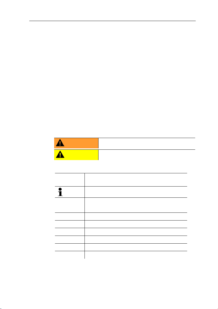
Maximum load
• 4-wire: 500 Ω (power output)
9
Page 10
4 Transmitter
Maximal load
• 4-wire: 10 kΩ (voltage output)
Analog output
• 0 to 1 V ± 1.5 mV (4-wire) or
• 0 to 5 V ± 7.5 mV (4-wire) or
• 0 to 10 V ± 15 mV (4-wire) or
• 0 to 20 mA ± 0.03 mA (4-wire) or
• 4 to 20 mA ± 0.03 mA (4-wire)
10
Resolution of analog output
• 12 bit
Relay
• 4 relays, 250 V AC/DC, 3 A (optional)
Display
• 2-line LCD with plain text line (optional)
Operating temperature
• -5 to 50 °C/23 to 122 °F
Page 11

4 Transmitter
Storage temperature
• -20 to 60 °C/-4 to +140 °F
Oper. humidity
• 0 to 90 % RH
Housing, weight
• Metal/plastic
• Version with integrated humidity probe: approx. 1.35 kg
• Version with preparation for external humidity probe: approx.
1.26 kg
Protection class, frontal
• IP 65 only if the transmitter is wired, Ethernet connector is
inserted and/or sealing plugs are inserted
Directives, standards and tests
• EC Directive: 2004/108/EC
• DIN 14644-4
• EN 61000-6-2 interference immunity
• EN 61000-6-3 interference emission
• EN 61326-1+A1+A2
Warranty
• Duration: 2 years
• Warranty conditions: see website www.testo.com/warranty
11
Page 12
4 Transmitter
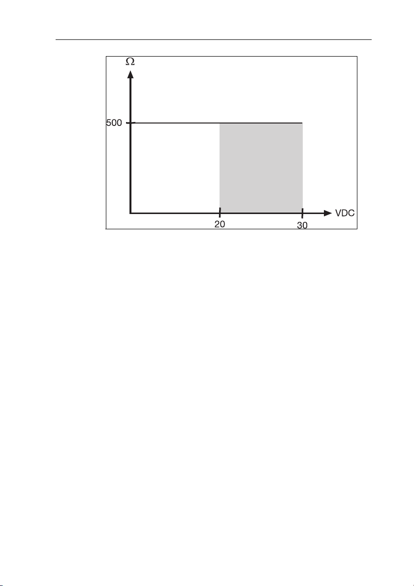
Pos: 25 /TD/Leistungsbeschreibung/Technische Dat en/MUF 63xx/MUF Panel lang Abmessungen @ 4\mod_1255092618 418_79.doc @ 51743 @ 3
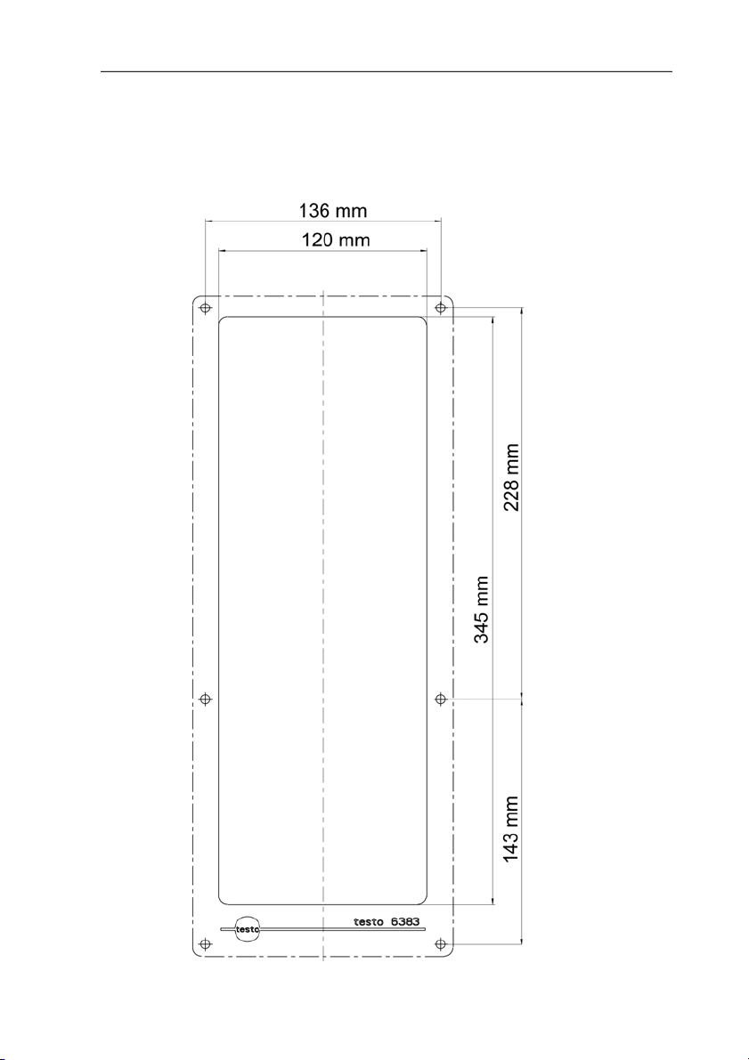
4.1.5. Dimensions
12
Page 13
4 Transmitter
Pos: 26 /TD/Überschriften/MUF/1.2/2.2 Produktb esc hreibung @ 3\mod_1234258723551_79.doc @ 24008 @ 2
4.2. Product description
Pos: 27 /TD/Produktbeschreibung/Übersicht/ MUF 63xx/Auf einen Blick 6385 @ 4\mod_1252500974490_79.doc @ 48933 @ 3
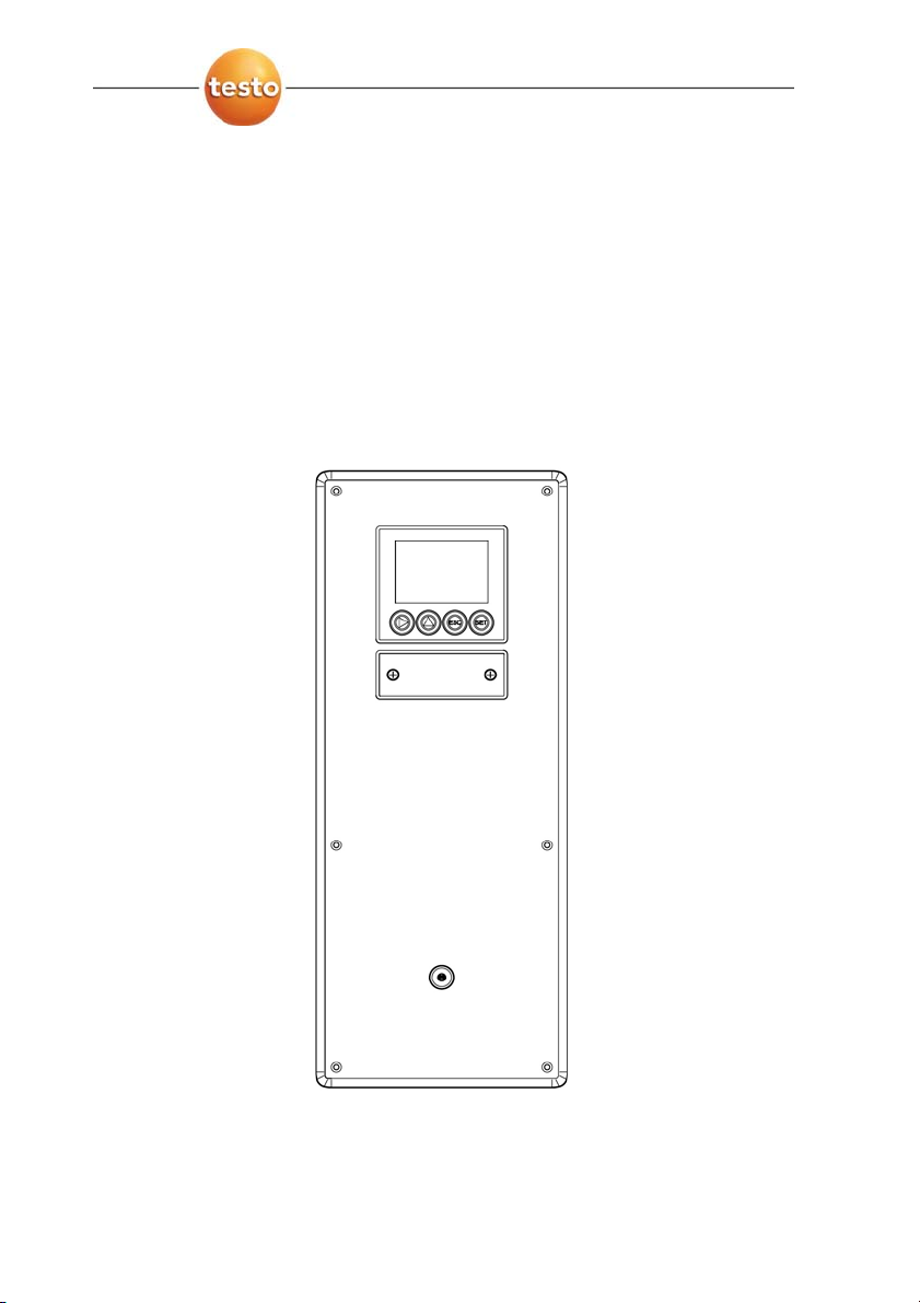
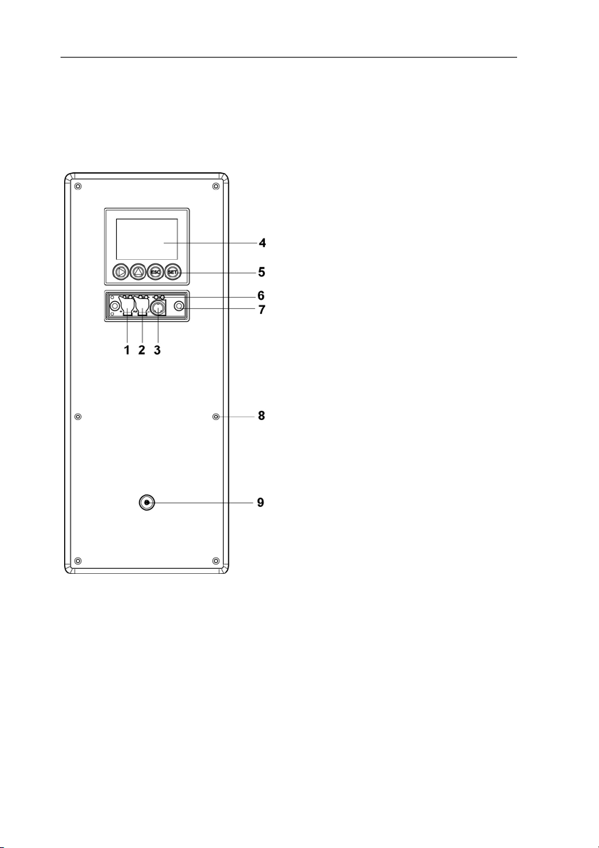
4.2.1. At a glance
1 Sealing p lugs on the positive
2 Sealing p lugs on the
3 Socket for service plug
4 Display (optio nal)
5 Keys (only with optional
6 Test rods for the ana log
7 Service cover screw
8 Openings for screws for
9 Only with inte grated humidity
pressure test connection (Ø
4 mm)
negative pressure test
connection (Ø 4 mm)
display)
outputs
connection (self-locking,
2 pcs.)
fastening to the wall
probe (KMAT option D04):
Opening for the integrated
humidity probe
13
Page 14
4 Transmitter
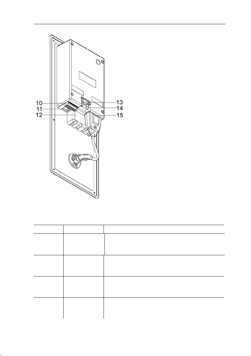
10 9-pin connector for the
current/voltage supply
11 Socket for Ethernet interface
12 Relay cover with 12-pin
connector underneath for
relay connection (option)
13 Negative pressure
connection (Ø 6,4 mm )
14 Positive pressure connection
(Ø 6,4 mm )
15 Probe socket
Pos: 28 /TD/Produktbeschreibung/Übersicht/ MUF 63xx/Verwendbare Fühler Panel @ 4\mod_1252670326817_7 9. doc @ 50119 @ 3
4.2.2. Usable probes
Probes Article no. Characteristic
Integrated
humidity
probe
testo 6613 0555 6610-L13
testo 6614 0555 6610-L14
testo 6615 0555 6610-L15
14
The testo 6383 transmitter can be used with the following probes:
KMAT option
D04
(0636 6610)
Wall probe version; accuracy to ±1 % RH;
temperature range -20 to +70 °C/-4 to +158 °F,
plug-on sensor
Cable probe version; accuracy to ±1 % RH;
temperature range -40 to +180 °C/
-40 to +356 °F, sensor soldered
Heated cable probe version; accuracy to ±1.0 %
RH; temperature range -40 to +180 °C/
-40 to +356 °F, sensor soldered
Trace humidity cable probe version; accuracy
±1 K at 0 °Ctd/+32 °Ftd; temperature range
-40 to 120 °C/-40 to +248 °F, sensor soldered
Page 15

Probes Article no. Characteristic
testo 6617 0555 6610-L17
Cable with cover electrode monitoring probe
version; accuracy to ± 1.2 % RH; temperature
range -40 to 180 °C/
-40 to +356 °F, sensor soldered
Pos: 29 /TD/Produktbeschreibung/Übersicht/ MUF 63xx/Display und Tastatur @ 3\mod_1234773965059_79.doc @ 25650 @ 3
4.2.3. Display and keypad
The display option allows operation of the testo 6383 transmitter via
the display and four keys.
The LCD display consists of two 7-segment lines for displaying
readings and units and of an information line (for status messages,
for example).
The brightness and contrast of the display and the background
lighting (permanent or off) can be changed via the user menu or the
Pos: 30 /TD/Überschriften/MUF/1.2.x Servicesc hni ttstelle @ 3\mod_1237306891654_79.doc @ 29795 @ 3
4.2.4. Service interface
Pos: 31 /TD/Produktbeschreibung/Übersicht/ MUF 63xx/Serviceschnittstelle 638x @ 3\mod_12347740929 11_79.doc @ 25669 @
Pos: 32 /TD/Produktbeschreibung/Übersicht/ MUF 63xx/Relaisplatine (Option) @ 3\mod_1234774184843_7 9.doc @ 25688 @ 3
P2A software.
The parameterizing socket (mini-DIN) is located behind the service
flap as an interface to the P2A software or Testo handheld
instrument (testo 400/testo 650).
4 Transmitter
4.2.5. Relay board (option)
This has a floating switch capacity of 250 V AC/3 A. The switching
limits and hysteresis as well as the function as relay for the
collective alarm can be set via the display or the P2A software.
Further features include:
• Function of changeover contacts (NC/NO contacts) freely
selectable
Pos: 33 /TD/Produktbeschreibung/Übersicht/ MUF 63xx/Analogausgänge 638x @ 3\mod_1234774341528_79.doc @ 25707 @ 3
15
• 12 terminals for a total of 4 relays.
If no relays are available, settings for monitoring limit values
or alarms can still be controlled via the display. The alarm
status will be shown on the display.
Only have the transmitter wired and connected by
authorized personnel with the voltage disconnected.
Page 16

4 Transmitter
4.2.6. Analog outputs
As analog outputs, the testo 6383 has either
• 1 or optionally 3 current outputs of 0 to 20 mA (4-wire)/4 to
20 mA (4-wire) or
• 1 or optionally 3 voltage outputs of 0 to 1 V/0 to 5 V/0 to 10 V
(4-wire).
The transmitter can be ordered with three analog outputs as an
option.
Pos: 34 /TD/Produktbeschreibung/Übersicht/ MUF 63xx/Messgrößen 6383/6385 @ 3\mod_1234774693900_79.d oc @ 25745 @ 3
The optional three channels are galvanically isolated.
4.2.7. Parameters
The following parameters are displayed
• Differential pressure in Pa, hPa, kPa, mbar, bar, mmH
O, inch HG, kg/cm2, PSI
H
2
• Relative humidity in % RH (technical)
• Relative humidity in % WMO* (calculation according to the
WMO standard)
• Degree of humidity in g/kg and gr/lb
• Absolute humidity in g/m³ and gr/ft³
• Water content in ppm (vol) and % vol
• Psychrometer temperature in °C
• Enthalpy in kJ/kg and BTU/lb
• Water vapour partial pressure in hPa and inch H
• Dewpoint temperature in °C
• Standardized dewpoint in °C
pressure (1013 hPa); precondition: Absolute process pressure.
• Dewpoint of H
* It is possible that condensation appears as of a displayed
humidity starting from 70 % and is shown on the display. This
unit is used in meteorology, amongst others. When calculating
the relative humidity the Magnus coefficient with undercooled
water is used in accordance with WMO.
Calculated humidity variables correspond to the medium of
air. With other gases/gas compositions, deviations may
occur, e.g. with the enthalpy.
• Temperature °C and °F
mixture in °Ctm and °Ftm.
2O2
and °Ftw
tw
O
2
and °Ftd
td
standardized at atmospheric
tdA ,
O, inch
2
16
Page 17

Pos: 35 /TD/Produktbeschreibung/Übersicht/ MUF 63xx/Skalierung @ 3\mod_1234775406989_79.doc @ 25783 @ 3
4.2.8. Scaling
There are three types of min./max. values:
1 The measuring range: The maximum sensor performance is in
this range. Values outside of the measuring range are displayed
via messages, for example. Measuring range, see table
(below).
2 Standard scaling: The output signals are assigned to this
measuring range as standard:
◦ during delivery if no entries are made in the order code
◦ after exchanging the unit, the measuring range recorded in
Pos: 36 /TD/Produktbeschreibung/Übersicht/ MUF 63xx/Tabelle Skalierung MUF Panel Druck @ 4\mod_12518181353 59_79.doc @ 48019 @
the instrument is applied as standard.
The transmitter even retains its scaling with the voltage
disconnected.
Measuring range, see table (below).
3 The maximum settings for the manual scaling
◦ The maximum limits can be calculated as follows:
X = difference between MIN. and MAX. value of the
standard scaling
(Max. value of standard) + (50 % of X)
(Min. value of standard) - (50 % of X)
◦ It is thus possible to scale beyond the measuring range, e.g.
for the adjustment of the scaling limits to standard values of
a PLC.
With the alarm definition, however, the physical measuring
range limits are decisive.
Measuring
range/standard scaling
0 to 50 Pa -5 to 15 Pa
0 to 50 Pa -25 to 75 Pa
0 to 100 Pa -50 to 150 Pa
0 to 500 Pa -250 to 750 Pa
0 to 10 hPa -5 to 15 hPa
-10 to 10 Pa -20 to 20 Pa
-50 to 50 Pa -100 to 100 Pa
-100 to 100 Pa -200 to 200 Pa
4 Transmitter
Maximum scaling
17
Page 18

4 Transmitter
-500 to 500 Pa -1000 to 1000
-10 to 10 hPa -20 to 20 hPa
Pos: 37 /TD/Produktbeschreibung/Übersicht/ MUF 63xx/Tabelle Skalierung Fühler Panel @ 5\mod_12575193882 89_79.doc @ 52767 @
Parameter Unit Probes
Temperature
°C 6611 -20 +70 -20 +70
°F 6611 -4 +158 -4 +158
°C
6613,
6614,
6617
°F
6613,
6614,
6617
°C 6615 -40 +120 -40 +120
°F 6615 -40 +248 -40 +248
Dewpoint
°Ctd 6611 -20 +70 -80 +100
°Ftd 6611 -4 +158 -112 +212
°Ctd
6613,
6614,
6617
°Ftd
6613,
6614,
6617
°Ctd 6615 -60 +30 -80 +100
6615 -76 +86 -112 +212
°F
td
3
all
probes
all
Absolute
humidity
g/m3
gr/ft
probes
relative humidity % RH
all
probes
WMO relative
% RH 0 100 0 100
humidity
Mixture dewpoint
(H
)
2O2
°Ctm -20 +100 -20 +100
°Ftm -4 +212 -4 +212
Physical
measuring range
at 1013 hPa
Standard scaling of
transmitter
measuring range
MIN MAX MIN MAX
-40 +180 -40 +180
-40 +356 -40 +356
-20 +100 -80 +100
-4 +212 -112 +212
0 600 0 2000
0 250 0 800
0 100 0 100
18
Page 19

4 Transmitter
Degree of
humidity
g/kg
gr/lb
all
probes
all
probes
kJ/kg -40 99999 -40 8000 Enthalpy
BTU/lb -18 43000 -18 3500
Psychrometer
temperature
°Ctw -40 100 -40 180
°Ftw -58 210 -40 356
ppm
0 99999 0 99999 Water content
(vol)
H
O
2
% vol 0 100 0 100
Water vapour
partial pressure
Pos: 38 /TD/Produktbeschreibung/Übersicht/ MUF 63xx/Alarmbehandlung @ 3\mod_1234776787635_79.doc @ 25821 @ 3
hPa 0 1000 0 7000
inchH2O 0 400 0 2800
4.2.9. Alarm handling
For upper and lower alarm limits, individual alarms as well as
collective alarms can be specified. If the collective alarm function is
activated, an alarm is triggered as soon as the alarm limit of an
alarm is exceeded, if this alarm is assigned to the collective alarm.
The testo 6383 monitors limit values with the help of relays. If a
reading is outside the limit values, a relay to be specified by the
user is switched.
If the reading reverts to more than a specified hysteresis below or
above the limit value, the alarm is cancelled.
In addition, information about the occurrence of error/status
messages can be provided by means of a collective alarm relay,
see Status, warning and error messages, page 64
If multiple alarm messages are activated at the same time,
the last alarm is shown. If the alarm is cancelled again, the
previous messages are no longer shown.
Physical
measuring range
at 1013 hPa
Standard scaling of
transmitter
measuring range
0 13300 0 9500
0 93000 0 66500
19
Page 20
4 Transmitter
Pos: 39 /TD/Überschriften/MUF/1.3/2.3 Inbetri ebnahme @ 3\mod_1234258805768_79.doc @ 24027 @ 2
4.3. Commissioning
Pos: 40 /TD/Erste Schritte/MUF 63xx/Wandmontage Panel @ 4\ m od_ 1251818568448_79.doc @ 48051 @ 3
4.3.1. Mounting preparations
20
Page 21

1. Create a wall opening (approx. 120 mm x 220 mm) at the
mounting location.
2. Hold 6383 in assembly position and mark the drill holes.
3. Drill holes suitable for the screws to be used.
Pos: 41 /TD/Erste Schritte/MUF 63xx/Gerät anschließ en P an el @ 4\mod_1252065506566_79.doc @ 48245 @ 3
4.3.2. Connecting the instrument
4. Connect 6383.
WARNING
Electrical voltage
Danger of injury!
> De-energize the mains connection before connecting the
transmitter.
Only have the transmitter wired and connected by
authorized personnel with the voltage disconnected.
4 Transmitter
21
Page 22
4 Transmitter
Pos: 42 /TD/Erste Schritte/MUF 63xx/Anschlussüber sicht 6383 @ 4\mod_1251708327447_79.doc @ 47697 @ 4
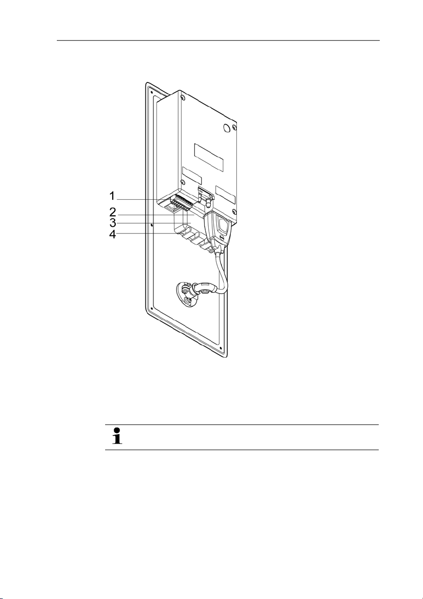
4.3.2.1. Overview of terminals
1 Terminal strip for voltag e
2 Relay terminal strip (option),
Pos: 43 /TD/Erste Schritte/MUF 63xx/Spannungsversor gung/Analogausgänge anschließen 6383/6385 @ 4\mod_1 254489681844_79.doc @ 51173 @ 45
22
3 Relay cover (option)
supply and analog outputs
4 Insulating trough for relay
below the relay cover
board (option), below the
relay cover
The following description of the terminals refer to this
overview and its numbering.
Page 23
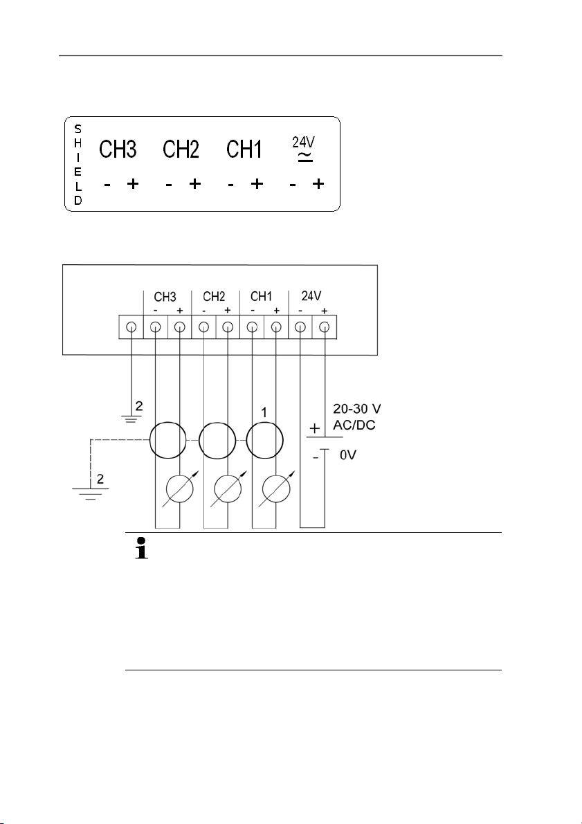
4.3.2.2. Connecting voltage supply and analog outputs
Terminal strip for voltage
supply and analog outputs,
item (1) of overview of
terminals
Wiring diagram for 4-wire system (0 to 20 mA/4 to 20 mA/0 to 1
V/0 to 5 V/0 to 10 V)
1 1 or 3 channels,
2 Functional earth
4 Transmitter
0 to 20 mA/4 to
20 mA max.
load per 500 Ω
0 to 1 V / 0 to
5 V / 0 to 10 V
Requirement for the connecting cable of the supply:
• Shielded and insulated with cross-section of at least
0.25 sq. mm, maximum 1.5 sq. mm without wire end
sleeves.
• The supply line must be secured against exceeding
0.5 A.
• An OFF switch must be installed in an easily accessible
position close by and be marked as such.
1. Disconnect terminal strip for voltage supply and analog outputs.
2. Strip the cable ends, clamp wire end ferrules on and screw
down with voltage terminals/channel terminals.
3. Tie together each of the two adjacent cores using a cable tie.
23
Page 24

4 Transmitter
Pos: 44 /TD/Erste Schritte/MUF 63xx/Relaisausgänge a nschließen Panel @ 4\mod_1251814425917_79.doc @ 47891 @ 4555
4.3.2.3. Connecting the relay outputs
4. Attach terminal strip for voltage supply and analog outputs.
Only have the transmitter wired and connected by
authorized personnel with the voltage disconnected.
There is the option of twelve terminals for a total of four relays.
1. Remove relay cover.
2. Disconnect relay terminal strip.
3. Strip cable ends and clamp on wire end ferrules.
4. Connect relays according to chosen function (NC/NO) (see
diagrams below; relay 1 is shown as an example of a
connection).
Connection note
Relay terminal strip,
item (2) of overview of
terminals
24
• For the connection, a double-insulated mains cable
(sheathed cable) with a cross-section of at least 1.5
mm² must be used.
• Cable connection (2) may not be routed in a loop within
the relay trough (1).
Page 25

4 Transmitter
• It is recommended that you always tie 2 adjacent cores
to one another using a cable tie (3).
• The insulation of the cable must be fed at least 5 mm
(4) into the relay tray up to the elevated part.
Use of relay as NC contact (NC = normally closed)
1 Alarm/status light
(example of installation)
2 250 V AC/DC, 3 A
The busy light (alarm/status light) is permanently on until
the relay opens or the circuit is interrupted. This circuit can
therefore be used to monitor the functionality of the alarm
circuit, as a cable break, for instance, is indicated by the
busy light going off.
25
Page 26

4 Transmitter
Use of relay as NO contact (NO = normally open)
1 Alarm/status light
(example of installation)
2 250 V AC/DC, 3 A
The busy light (alarm/status light) only comes on when the
relay is switched (closed). Monitoring the functionality of the
alarm circuit is therefore not possible with this switching
operation.
5. Insert relay terminal strip into socket.
6. Set on relay cover.
26
Page 27

Pos: 45 /TD/Erste Schritte/MUF 63xx/Gerät schließen 6 385 @ 4\ mod_1254754601578_79.doc @ 51379 @ 4
4.3.2.4. Closing the instrument
4 Transmitter
1. Connect probe.
• Version with integrated humidity probe:
1. Insert probe into probe socket.
2. Guide probe through opening of front plate.
3. Tighten screw at opening.
• Version with external humidity probe:
> Insert probe into probe socket.
4. Slide Ethernet connector into Ethernet socket.
27
Page 28

4 Transmitter
5. Pull sealing frame (1) over the edge of the 6383.
6. Screw on 6383. Initially, only tighten the screws slightly. When
7. Seal 6383 using a measure appropriate for the installation point
Pos: 46 /TD/Erste Schritte/MUF 63xx/Ethernet-spe zifisch/Kommunikation Ethernet ohne Saveris @ 4\ mod_1 2523 14949577_79.doc @ 48477 @ 3444
28
all screws are in position, also align 6383 and tighten the
screws.
(e.g. with a silicone strip).
Page 29

4.3.3. Ethernet communication
4.3.3.1. Types of operation
A corresponding testo 6383 can be integrated into any Ethernet
systems
4.3.3.2. Mains connection
4.3.3.3. Setting the IP address
Pos: 47 /TD/Erste Schritte/MUF 63xx/Ethernet-spe zi fisch/Integration Ethernet-System 638x @ 3\mod_ 1238 749834421_79.doc @ 30793 @ 4555555555
> Connect the network cable to the transmitter.
The network cable must not be connected directly to the
telephone network (ISDN).
✓ Network cable must be conne cted to the Ethernet interface.
✓ Service plug must be inserted.
The IP address of the transmitter will be set via the P2A software
(transmitter accessories).
1. Set IP address with the P2A software (see Using the software,
page 116).
2. Disconnect service plug.
4 Transmitter
4.3.3.4. Integration into customer's Ethernet system
29
Precondition
The user should be familiar with the structure of an XML
document. Furthermore, enough knowledge should be
available that this type of document can be downloaded
and decoded via an Internet connection with the aid of a
programming/script language.
Interface
The communication takes place according to the client/server
principle, whereby the Ethernet module takes on the role of the
server:
The XML interface will be approached via a URL. The URL consists
of the IP address of the Ethernet module, the path for the XML
document and, depending on the URL, with a clearly defined
parameter. If a parameter is missing or an incorrect value is
Page 30

4 Transmitter
transferred, the Ethernet module sends back a simple error
message.
Example:
IP address = 254.169.100.100
URL for serialnumber.xml:
http://254.169.100.100/data/getserialnumber
If a parameter is required, a "?" is always in the first place after the
URL, then the parameter is transferred to the common query string
form (name=value).
Example:
IP address = 254.169.100.100
URL for / identification.xml:
http://254.169.100.100/data/getidentification?param=0 (compare
table xml codes)
After calling up the compound URL, if everything was correct, an
XML document is returned. With faulty parameters a simple
HTML answer comes that points out the reason that an XML
answer could not be given.
If an XML document is to be loaded on the server, access is
provided by means of a POST request
Example of an upload via the program wget:
IP address = 254.169.100.100
URL for / usersettings.xml:
Path details of the folder in which
the wget program is located
H:/wget/wget-complete-stable /wget --post-file= C:/usersettings.xml 254.169.100.100/config/
Command Path details of the
folder in which the
usersettings XML file is
located
IP address of the transmitter
and required URL (see table on
the next page)
setusersettings
The Ethernet module supports reading out of
• Readings
• Instrument type (testo 6383)
• Firmware date and version (testo 6383)
• Status and status messages (testo 6383)
• Alarm messages (testo 6383)
• Service hour counter (testo 6383 and probe)
as well as the reading and writing of the:
• Adjustment data (testo 6383)
30
Page 31

• Configuration data of analog outputs (testo 6383)
• Configuration data of relays (testo 6383)
• User settings (testo 6383)
XML codes (download)
The table of XML codes is available for download at
www.testo.de/transmitter
as well as on the product CD
URL Description Parameter
/data/getserialnumber Read off serial number of
/data/getidentification Read off type of
/data/getversion Read off firmware version
/data/getfirmwaredate Read off firmware date of
/data/getonlinevalue Read off online values of
/data/getviewchannels Read off view channels of
/data/getstatus Read off status of
/data/getlaststatusmessa
ge
/config/gethourscount Read off service hour
/config/getusersettings Read off settings of
/config/getcalibration Read off adjustment data
/config/getreldefinition Read off relay information
/config/getheatertime Read off sensor heating
connected transmitter
connected transmitter/
probe
of connected transmitter
connected transmitter
connected transmitter
connected transmitter
connected transmitter
Read off last status
message of connected
transmitter
counter of transmitter or
probe
transmitter
of transmitter
of transmitter
information
param=0 (for transmitter)
param=1 (for probe)
param=0 (adjustment set 1)
param=1 (adjustment set 2)
param=2 (adjustment set 3)
param=0 (relay 1)
param=1 (relay 2)
param=2 (relay 3)
param=3 (relay 4)
4 Transmitter
Answer (see
Appendix)
serialnumber.xml
identification.xml
version.xml
firmwaredate.xml
onlinevalue.xml
viewchannels.xml
status.xml
laststatusmessage.xml
hourscount.xml
usersettings.xml
calibration.xml
reldefinition.xml
heatertime.xml
31
Page 32

4 Transmitter
URL Description Parameter
/config/getoptions Read off options of
/config/getcollectivealarm Read off alarm messages
transmitter
of transmitter
Upload XML documents
URL Description Parameter Post
/config/setusersettings
/config/setcalibration Set adjustment data of
/config/setreldefinition Set relay information
/config/setheatertime Set sensor heating
/config/setoptions Set options of
/action/setresettm Not yet implemented
Perform settings of
transmitter
transmitter
of transmitter
information
transmitter
param=0 (adjustment
set 1)
param=1 (adjustment
set 2)
param=2 (adjustment
set 3)
param=0 (relay 1)
param=1 (relay 2)
param=2 (relay 3)
param=3 (relay 4)
usersettings.xml usersettings.xml
calibration.xml calibration.xml
reldefinition.xml reldefinition.xml
heatertime.xml heatertime.xml
options.xml options.xml
resettm.xml
Answer (see
Appendix)
options.xml
collectivealarm.xml
Answer (see
Appendix)
Description of the XML elements
General elements
XML tag Description Type
measurement_value Parent element. Contains the child
value Reading Numerical, decimal number
unit Unit ASCII
number_values Qty. Numerical, whole number
elements value, unit, resolution
32
Page 33

4 Transmitter
Elements in calibration.xml
XML tag Description Type
calibration_data Base element. Contains the child
elements unit, attenuation,
cal_reserved, cal_offset, cal_scale.
unit See general elements
attenuation Damping (0 - 15) Numerical, decimal number
cal_offset Offset Numerical, whole number
cal_scale Parent element. Contains the child
elements cal_minscale, cal_maxscale
cal_minscale Scaling value Numerical, decimal number
cal_maxscale Scaling value Numerical, decimal number
Elements in collectivealarm.xml
XML tag Description Type
colalarmtable Base element. Contains the child
alarm_numbers Number of alarm messages Numerical, whole number
alarm Parent element . Contains the child
alarm_event Type of alarm ASCII
alarm_state
elements alarm_numbers, alarm
elements alarm_event, alarm_state
Status of the alarm
0 = alarm inactive
1 = alarm active
Numerical, whole number
Elements in firmwaredate.xml
XML tag Description Type
firmware_date Base element. Contains the child
year Year Numerical, whole number
month Month Numerical, whole number
day Day Numerical, whole number
elements year, month, day
Elements in heatertime.xml
XML tag Description Type
heatertime Base element. Contains the child
element heatertimeoff
heatertimeoff Time sensor heating off in min Numerical, whole number
33
Page 34

4 Transmitter
Elements in hourscount.xml
XML tag Description Type
hourcount Base element. Contains the child
element hours
hours Service hour counter in h Numerical, whole number
Elements in identification.xml
XML tag Description Type
ident Base element. Contains the child
device_id Transmitter typ e Numerical, whole number
element device_id
Elements in laststatusmessage.xml
XML tag Description Type
mufmsg Base element. Contains the child
elements msg, sn, hours
msg Status message ASCII
sn Serial number ASCII, 8 characters
hours Service hour counter in h Numerical, whole number
Elements in onlinevalue.xml
XML tag Description Type
online_values Base element. Contains the child
number_values See general elements
measurement_value See general elements
elements number_values,
measurement_value
Elements in options.xml
XML tag Description Type
options Base element. Contains the child
device_options See device_options description Numerical, whole number
production_options See production_options description Numerical, whole number
elements device_options,
production_options
34
Page 35

4 Transmitter
Elements in reldefinition.xml
XML tag Description Type
relay_data Base element. Contains the child
relay_channel Measurement channel linked to the
relay_number Relay number (0 - 2) Numerical, whole number
relay_status
sw_point_charact
sw_point_value Switch point Numerical, decimal number
hysteresis_value Hysteresis Numerical, decimal number
elements relay_channel, relay_number,
relay_status, sw_point_character,
sw_point_value, hysteresis_value
relay
Status of relay
0 = off
1 = on
Switch point: Switch point:
0 = low-limit monitoring
1 = high-limit monitoring
Numerical, whole number
Numerical, whole number
Numerical, whole number
Elements in serialnumber.xml
XML tag Description Type
serialnumber Base element. Contains the child
number Serial number ASCII, 8 characters
element number
Elements in status.xml
XML tag Description Type
mufstatus Base element. Contains the child
statemsg
staterel
statecounter Counter Numerical, whole number
35
elements statemsg, staterel,
statecounter
Status message
See statemsg description
Status relay
See staterel description
Numerical, whole number
Numerical, whole number
Page 36

4 Transmitter
Elements in usersettings.xml
XML tag Description Type
usersettings Base element. Contains the child
pressure Absolute pressure Numerical, decimal number
h2o2 H2O2 value Numerical, decimal number
setting_display
backlight
contrast
language
disp_msg
h2o2_prozess
abs_pressure_pa_process,
humidity_process
temperature_c_process
abs_pressure_pa
elements (pressure)*
(abs_pressure_pa_process)*,
(humidity_process)*,
(temperature_c_process)*,
(humidity_norm)*, (abs_pressure_pa)*,
h2o2, setting_display, backlight,
contrast, language, disp_msg,
h2o2_prozess
Auto OFF background lighting
0 -> background lighting auto off
1 -> background lighting stays on
Brightness of background lighting
0 to 9 (0 = off, 9 = max.)
Display contrast
0 to 9 (0 = min., 9 = max.)
Language
0 ->GERMAN
1 ->ENGLISH
2 ->FRENCH
3 ->SPANISH
4 ->ITALIAN
5 ->JAPANESE
6 ->SWEDISH
Status messages display
0 = off
1 = on
H2O2 process
0 = via H2O2 water
1 = process with evaporated H2O2
Pressure process data, absolute
pressure in Pa
Pressure process data, process
humidity in % RH
Pressure process data, process
temperature in °C
Humidity process data, absolute
pressure in Pa
3
,
Numerical, whole number
Numerical, whole number
Numerical, whole number
Numerical, whole number
Numerical, whole number
Numerical, whole number
Numerical, decimal number
Numerical, decimal number
Numerical, decimal number
Numerical, decimal number
* Child elements are optional
36
Page 37

4 Transmitter
Elements in versions.xml
XML tag Description Type
firmware_version Base element. Contains the child
version Firmware version: ASCII, 6 characters
element version
Elements in viewchannels.xml
XML tag Description Type
view_channels Base element. Contains the child
elements number_values, view_channel
number_values See general elements
view_channel Parent element. Contains the child
elements channel_info,
measurement_value, meas_status
channel_info Parent element. Contains the child
elements connector_info, channel_type
measurement_value See general elements
meas_status Parent element. Contains the child
elements min, max, mean
connector_info Channel (transmitter/probe) ASCII
channel_type Parameter details ASCII
min. Minimum reading Numerical, decimal number
max. Maximum reading Numerical, decimal number
mean Mean value Numerical, decimal number
production_options description
Content of production_options is a double word type number (32
bit). The individual hardware options are bit-coded here.
xxxx xxxx xxxx xxxx xxxx xxx1 2222 3334
1 0=2-wire
1=4-wire
2 free
3 0=4 to 20 mA
1=0 to 20 mA
2=0 to 1 V
3=0 to 5 V
4=0 to 10 V
37
Page 38

4 Transmitter
xxxx xxxx xxxx xxxx xxxx xxx1 2222 3334
4 0=1 analog output
1=3 analog outputs
device_options description
Content of device_options is a double word type number (32 bit).
The individual instrument options are bit-coded here.
xxxx xxxx xxxx xxxx xxxx xxxx 1222 2345
1 0=probe is invalid
1=probe is valid
2 free
3 free
4 0=no relay present
1=relay present
5 0=no display
1=display present
statemsg description
Content of statemsg is a double word type number (32 bit). The
individual status messages are bit-coded here.
If statemsg = 0 there are no new messages.
If statemsg != 0
xxxx xxxx xxxx xxxx xxxx xxxx 1234 5678
1 free
2 1=probe information
3 1= probe warning
4 1=probe error
5 free
6 1=transmitter information
7 1=transmitter warning
8 1=transmitter error
38
Page 39

staterel description
Content of staterel is a double word type number (32 bit). The
individual relay states are bit-coded here.
xxxx xxxx xxxx xxxx xxxx xxxx xxxx 1234
1 0=relay 4 is not set
1=relay 4 is set
2 0= relay 3 is not set
1=relay 3 is set
3 0=relay 2 is not set
1=relay 2 is set
4 0=relay 1 is not set
1=relay 1 is set
More information can be found in the download area at
Pos: 48 /TD/Erste Schritte/MUF 63xx/Gerät abgleic hen 6383/ 6385 @ 4\mod_1252502215678_79.doc @ 49029 @ 4
www.testo.com.
4.3.3.5. Adjusting the instrument
The testo adjusting concept allows the entire signal chain from the
sensor signal (probe) and the digital signal (within the transmitter)
through to the analog signal (transmitter output signal) to be
adjusted (see diagram).
1-point adjustment
4 Transmitter
Adjustment via
• testo 400/650
handheld instrument
with adjustment
adapter
• P2A software
• User menu
39
Page 40

4 Transmitter
Analog adjustment n-point adjustment
Adjustment using a
precise multimeter and
transmission of analog
reference value in
• User menu or
• P2A software
Adjustment using a
precise pressure sensor
and transmission of
analog reference value in
• User menu or
• P2A software
The 1-point adjustment is suitable for adjusting the sensor signal digital signal chain.
The testo 6383 transmitter has digital probes whose adjustment
information is stored in the probes' internal memory. The 1-point
adjustment can thus be carried out on another testo 6383 (e.g. in
Pos: 49 /TD/Erste Schritte/MUF 63xx/Übersicht Abgleic htasten und Prüfkontakte 6383/6385 @ 4\mod_125250291 4330_79.doc @ 49061 @ 4
4.3.3.6. Overview: Adjustment keys and test contacts
the calibration laboratory).
1 Contact ch. 1
2. Contact ch. 2
3. Contact ch. 3
4. Service interface
40
Page 41

Pos: 50 /TD/Erste Schritte/MUF 63xx/1-Punkt-Abgleic h (Offset) @ 3\mod_1234790066779_79.doc @ 26106 @ 45
4.3.3.7. 1-point adjustment (offset - humidity/temperature)
In the 1-point adjustment, the reading at the working point is raised
to the reference value so that there is no longer any deviation in the
working point. The reference condition can be measured using a
precise handheld instrument (e.g. testo 400/650 with precision
humidity probe) or be created in an air conditioning cabinet.
1 Deviation
2 Working point
3 Working range
The advantage of the 1-point adjustment is the good measuring
result in the working range. But the further away the measurement
is from the working point, the greater the deviation can become.
The 1-point adjustment should therefore only be used for a
relatively narrow measuring range (working range), e.g. clean room
applications, air conditioning applications for storage and similar.
The 1-point adjustment can be performed
• via the user menu (see Editing Main Menu Adjust, page 61) or
• via the P2A software (see volume 2, 1-point adjustment, page
135) or
• directly by means of a Testo handheld instrument
(testo 400/650) (see description of how to proceed below).
Please note that the 1-point adjustment is generally performed on
the basis of the % RH and °C/°F parameters.
4 Transmitter
Adjusting testo 6383 using testo handheld instrument
✓ The service flap is open, a testo 400/650 handheld instrument
with a precision humidity probe is ready.
41
Page 42

4 Transmitter
Pos: 51 /TD/Erste Schritte/MUF 63xx/Hinweis 6614, 6615 @ 3\ mod_1234791706885_79.doc @ 26163 @
1. Connect testo handheld instrument 400/650 (1) with connected
humidity reference probe (3) (order no. reference set
0699 3656/20) to the service interface (5) of the testo 6383 via
the adjustment adapter (2) (connected to probe socket 1 of the
handheld instrument).
2. Expose the humidity probe (4) of the testo 6383 and the
reference probe (3) to the same reference conditions (e.g. in
the humidity generator) and allow climatic conditions to
equalize.
3. Switch on the testo 400/650. The two-part display of the
handheld instrument will show the values of the transmitter on
the left, and the values of the reference probe on the right. The
humidity and temperature values are adjusted to the reference
probe using the Probe > Probe Adjustment menu item on the
testo 400/650. The 1-point adjustment is performed for both the
humidity and the temperature.
4. Disconnect the adjustment adapter (2) from the service
interface (5).
5. Close the service flap.
Adjustment with the standard testo adjustment salt pots is
not suitable for the testo 6614 (heated for high-humidity
applications) and testo 6615 (trace humidity) probes.
The reference conditions should be generated in a humidity
generator to adjust these probes. In addition, these probes
can also be adjusted at a third adjustment point by Testo
Service.
• testo 6614: third adjustment point at 90 % RH
• testo 6615: third adjustment point at -40 °C
/-40 °Ftd
td
42
Page 43

Pos: 52 /TD/Erste Schritte/MUF 63xx/Analogausgangs- Abgleich 6383/6385 @ 4\mod_1252498044594_79.doc @ 48837 @ 45
4.3.3.8. Analog output adjustment
The purpose of adjusting the analog outputs is to adjust the signal
chain from the digital signal (within the transmitter) to the analog
outputs. The signal type that was appointed for the transmitter is
adjusted respectively for each channel (e.g. 4 to 20 mA or 0 to 1 V,
etc.).
4 Transmitter
1 Contact ch. 1
2. Contact ch. 2
3. Contact ch. 3
4. Service interface
Adjusting analog outputs 1, 2 and 3 (optional)
✓ With testo 6383 with current output: Load of max. 500 Ω is
connected to channel that is to be adjusted (see Connecting
voltage supply and analog outputs, page 23).
✓ A precise multimeter (minimum requirement: resolution 6.5
digits, at least 5-times more accurate than the 6383) is
available.
If only a simple multimeter is available, the analog outputs
must not be adjusted.
✓ The service cover is open.
1. Connect the inputs of the multimeter with the contacts (1) and
(2) for channel 1 or with contacts (3) and (4) for channel 2, (5)
and (6) for channel 3.
43
Page 44

4 Transmitter
2. Transfer the reference analog value measured with the
multimeter into the P2A software (see volume 2, Adjusting the
analog output, page 138) or enter it via the user menu (see
Editing Main Menu Adjust, page 61).
3. Disconnect connections between the multimeter and the
Pos: 53 /TD/Erste Schritte/MUF 63xx/n-Punkt-Abgleic h _638x @ 3\mod_1237384429887_79.doc @ 29990 @ 4
contacts of the testo 6383 and close the service cover.
4.3.3.9. n-point adjustment (pressure)
With an n-point adjustment, the parameters at the 3-6
measurement points are adjusted to the reference value. The
reference conditions are obtained by using a precise pressure
sensor that should be 5-times more accurate than the transmitter.
1 Positive pressu re connection
2. Negative pressure connection
3. Pressure sensor
44
The number of measuring points is set to 3 by the factory
and can only be changed using the P2A software (see n-
point adjustment page 137)
The n-point adjustment must always be carried out to its full
extent and in good time at all selected measurement points.
✓ A precise pressure sensor (5-times more accurate than the
transmitter, e.g. DPC precision pressure sensor from testo
industrial services) is available.
1. Connect the positive output of the pressure sensor (3) to the
positive pressure connection of the transmitter (1) and the
negative output of the pressure sensor (3) to the negative
pressure connection of the transmitter (2).
2. Transfer the reference pressure value created with the pressure
sensor into the P2A software (see volume 2, n-point
adjustment, page 137) or enter it via the user menu (see Editing
Main Menu Adjust, page 61).
3. Repeat step 2 for all of the measuring points.
Page 45

4. Disconnect connections between the pressure sensor and the
Pos: 54 /TD/Erste Schritte/MUF 63xx/Hochfeuchteabg leich beim testo 6614 @ 3\mod_1235661029461_79.doc @ 26922 @ 4
4.3.3.10. High-humidity adjustment for testo 6614
pressure connections of the testo 6383.
4 Transmitter
With the testo 6614, the rear of the Testo humidity sensor is
heated, creating a microclimate around the sensor (within the filter)
that is constantly 5 K warmer than the actual process conditions.
As can be seen in the Mollier diagram, this reduces the relative
humidity at the sensor from around 100 % RH to a lower value, e.g.
73 % RH. In this range, the reaction time of the sensor is noticeably
shorter than in the condensation range and the risk of the sensor
corroding is also reduced. Using the separate temperature probe,
the testo 6383 transmitter compensates the microclimate conditions
and displays the process readings.
The reference conditions (11.3 % RH and 75.3 % RH) for
the 2-point adjustment of the testo 6614 should be
generated in a humidity generator, as humidity adjustment
sets cannot be used due to the heat generated.
The adjustment can also be carried out at a third
adjustment point (90 % RH) by Testo Service so that
optimum accuracy is also achieved in the high humidity
ranges.
45
Page 46

4 Transmitter
Pos: 55 /TD/Erste Schritte/MUF 63xx/Selbstabgleic h des Restfeuchtefühlers testo 6615 @ 3\mod_1235661074 070_79.doc @ 26942 @ 4
4.3.3.11. Self adjustment of testo 6615 trace humidity probe
Conventional trace humidity probes show a steep rise in measuring
uncertainty at low humidities. In the testo 6615 trace humidity
probe, these measuring uncertainties are corrected by means of an
automatic self-adjustment process. This means that extremely
accurate measuring results are also attained to -60 °Ctd.
To this end, a temperature sensor is fitted on the back of the
testo 6615 which is used as a heater. A humidity and temperature
value pair is taken in both the unheated and heated state. The
deviation of the probe obtained from these pairs of values is
automatically corrected.
46
• Deactivating the adjustment function of the testo 6615
will reduce measuring accuracy and should therefore be
restricted to the shortest possible length of time.
• During the heating phase, the relay and analog outputs,
the display value and output value are "frozen", see
diagram above. Self-adjustment active is shown in the
display until it has finished. The factory setting for selfadjustment time (incl. heating time, calculation time,
cooling time) requires 30 minutes daily.
• In the factory setting, a third adjustment point
(-40 °Ctd) is approached for the testo 6615 in addition to
Page 47

4 Transmitter
the 2-point adjustment.
This special adjustment can be performed again by your
Pos: 56 /TD/Überschriften/MUF/1.4 Bedienung @ 3\mod_ 1234 443160034_79.doc @ 25001 @ 2
4.4. Operation
Pos: 57 /TD/Produkt verwenden/MUF 63xx/Zusammenhang Bedi enmenü – Mini DIN Buchse aktiv @ 3\mod_1234454016014_79. doc @ 25213 @ 3
Testo Service team if necessary.
4.4.1. Relationship between user menu and mini-DIN
socket is active
The testo 6383 can be parameterized using either the user menu or
the P2A software (see volume 2, Parameterizing, adjusting and
analyzing software (P2A software) page 113).
The testo 6383 transmitter can only be operated via the
display and keypad if the display option is available.
If the testo 6383 is connected to the P2A software, the user
menu is blocked for the duration of the communication. The
message Service plug is shown in the display of the testo
6383. As soon as the P2A software is disconnected, the
Pos: 58 /TD/Produkt verwenden/MUF 63xx/Passwortschu tz _638x @ 3\mod_1234455136144_79.doc @ 25251 @ 3
user menu is accessible again.
4.4.2. Password protection
The user menu can be protected with a four-digit numerical code
(see Editing Main Menu Settings, page 55) so that access to the
user menu is denied to unauthorized persons not familiar with this
numerical code.
If the password protection is not to be used, the numerical code
Pos: 59 /TD/Produkt verwenden/MUF 63xx/Aufbau des Bedien menüs 638x @ 3\mod_1234455236596_79.doc @ 25270 @ 3
"0000" must be entered. This is also the status upon delivery.
4.4.3. Structure of user menu
At the main menu level, the user menu comprises the following:
• Main Menu Channel 1
• Main menu of channel 2 (if this option is available)
• Main menu of channel 3 (if this option is available)
• Main Menu Alarm
• Main Menu Settings
• Main Menu Analysis
• Main Menu Messages
• Main Menu Ident
• Main Menu Adjust
47
Page 48

4 Transmitter
• Main Menu Reset
1 Channe l 1 display
2 Channe l 2 display
3 Channel 3 display or for
messages
Four keys enable the user to navigate/scroll through the menus and
enter/amend values and settings:
Key Function/description
SET
• In Measuring Mode: changes to
parameterization
• In Parameterizing Mode: confirms a
selection or setting
ESC
• Leaves a menu (without modifying any
settings)
X • Selecting: scrolls through menus
(downwards) or selectable alternatives
• Editing: changes to next digit (to the right)
S • Selecting: scrolls through menus (upwards)
or selectable alternatives
• Editing: increases the value of the current
digit by 1
48
Page 49

Pos: 60 /TD/Produkt verwenden/MUF 63xx/Übersicht Bedi en menü @ 3\mod_1234510821302_79.doc @ 25303 @ 3
4.4.4. Overview of the testo 6383 user menu
4 Transmitter
49
Page 50

4 Transmitter
50
Page 51

4 Transmitter
51
Page 52

4 Transmitter
Pos: 61 /TD/Produkt verwenden/MUF 63xx/Hauptmenü Kanä le be arbeiten @ 3\mod_1234511119158_79.doc @ 25322 @ 34
4.4.5. The individual main menus
4.4.5.1. Editing main menu of channel 1
An overview is given in Overview of the testo 6383 user menu,
page 49).
You can perform basic settings for channel 1.
1. In the Measuring Mode press SET, select Main Menu
Channel 1 with X or S and confirm selection with SET.
One of the following parameters can now be selected using X
or S, after which the selection must be confirmed with SET:
• Channel 1 Unit
The parameter for this channel is selected.
Edit/select parameter with X or S, confirm with SET or abort
entry with ESC.
• Scale minimum for channel 1:
The lower scale limit is edited; Unit as selected above.
Editing the value: Scroll one digit to the right using X and
increase value of digit by 1 using S. Confirm with SET or abort
entry with ESC.
• Scale maximum for channel 1
The upper scale limit is edited;
Unit as selected above.
Editing the value: Scroll one digit to the right using X and
increase value of digit by 1 using S. Confirm with SET or abort
entry with ESC.
• Signal delay ("Attenuation") for channel 1
The analog signal can be delayed ("Attenuation"); a time
constant is selected for this (1 = no delay; 15 = longest delay)
Edit/select parameter with X or S, confirm with SET or abort
entry with ESC.
2. Continue to the main menu with X or S or return to Measuring
Pos: 62 /TD/Produkt verwenden/MUF 63xx/Hauptmenü Kana l 2/ 3 638x @ 3\mod_1236085000820_79.doc @ 27312 @ 44
Mode with ESC.
4.4.5.2. Editing Main Menu Channel 2 (if this option is available)
See channel 1.
52
Page 53

4 Transmitter
4.4.5.3. Editing Main Menu Channel 3 (if this option is available)
Pos: 63 /TD/Produkt verwenden/MUF 63xx/Hauptmenü Alar m bearbeiten 638x @ 3\mod_1234518541385_79.doc @ 25341 @ 455
See channel 1.
4.4.5.4. Editing Main Menu Alarm
With the alarm, the relays, available as options, are programmed.
In addition, the alarm statuses are shown on the display (top right)
(even without relays).
You can choose whether the alarm is to be used to monitor limit
values or as a collective alarm. If an alarm is to be used to monitor
limit values, you can choose between monitoring the minimum or
maximum value and set a limit value and hysteresis for each alarm.
In addition, every alarm can be linked to a clearly visible visual
alarm (display background lighting flashes).
An alarm delay between 0 and 240 seconds can still be assigned to
every alarm used for limit value monitoring so that both the
corresponding relay effect and the visual alarm are delayed. If the
alarm status goes out within the set alarm delay time, neither the
visual alarm nor a relay connection is triggered. .
With an alarm status present, the visual alarm and all relay outputs
can be reset by means of acknowledgement. The triggering of a
new alarm cannot be enabled until after the alarm status goes out.
1. In the Measuring Mode press SET, select Main Menu Alarm
with X or S and confirm selection with SET.
- Four alarms can be parameterized.
2. Select Alarm x with X or S and confirm selection with SET.
Using alarm to monitor limit values
NO contact
Monitoring minimum Monitoring maximum
Hysteresis
Limit value Limit value
53
Hysteresis
Page 54

4 Transmitter
NC contact
Monitoring minimum Monitoring maximum
Hysteresis
Hysteresis
Limit value Limit value
3. Select Channel x (e.g. "Channel 1") with X or S and confirm
selection with SET.
4. Select Max control or Min control with X or S (see graphic).
5. Press SET and edit Limit value as well as Hysteresis: Scroll
one digit to the right using X and increase value of digit by 1
using S. Confirm with SET or abort entry with ESC.
6. Select Visual alarm with X or S. Select YES or NO with X or
S. Confirm with SET or abort entry with ESC.
7. Press SET and edit Alarm delay: Scroll one digit to the right
using X and increase value of digit by 1 using S (0 to 240
seconds possible). Confirm with SET or abort entry with ESC.
8. Return to Channel x with ESC.
9. Return to Alarm x with ESC.
10. Change to the other relays using X or S and perform settings
in the same
w
ay.
Using alarm as collective alarm or not using it at all
If an alarm is assigned to the collective alarm, the relay is switched
and a visual alarm can be issued via the display as soon as (at
least) one of the warning or error messages of the testo 6383
transmitter (or the connected testo 6610 probe) becomes active.
The messages affecting the collective alarm can only be
selected in the P2A software, see volume 2, Using the
software, page 116.
✓ Alarm is selected (see previous steps 1 and 2).
1. Use X or S to determine whether Alarm x should be used as a
Collective alarm or not used. Confirm selection with SET.
2. If collective alarm is selected: Select Visual alarm with X or S.
Select YES or NO with X or S. Confirm with SET and return to
Alarm x.
54
Page 55

3. Change to another alarm using X or S and perform settings in
the same way.
4. Return to Main Menu Alarm with ESC.
5. Continue to Main Menu Settings with X or S or return to
Pos: 64 /TD/Produkt verwenden/MUF 63xx/Hauptmenü Einst ellungen bearbeiten 6383/6385 @ 4\mod_1252503503580 _79.doc @ 49125 @ 455555
Measuring Mode with ESC.
4.4.5.5. Editing Main Menu Settings
You can edit instrument settings and other settings.
> In Measuring Mode, press SET, select Main Menu Settings
using X or S and confirm selection with SET.
You can edit settings for:
• Display
• Language
• Code
• Units
◦ Absolute pressure
◦ Area
◦ Temperature
• Humidity process data
◦ H2O2 percentage by weight
◦ Humidity process pressure
4 Transmitter
Editing display settings
You can set the brightness and contrast of the display.
1. Select Display Settings with X or S and confirm selection with
SET.
2. Select Backlight or Contrast with X or S and confirm
selection with SET.
One of the following parameters can now be selected using X or
S, after which the selection must be confirmed with SET:
• Backlight
The display illumination is changed.
Edit/select parameter with X or S, confirm with SET or cancel
entry with ESC (the effect of the change in parameter can be
seen during input).
55
Page 56

4 Transmitter
• Contrast
The brightness difference between the display background and
the displayed values is changed.
Edit/select parameter with X or S, confirm with SET or cancel
entry with ESC (the effect of the change in parameter can be
seen during input).
• Backlight 24h on
Select On or Off using X or S and confirm with SET.
Off: The display light switches off automatically if no button was
pressed for 10 seconds.
On: The display light is activated
3. Return to Display Settings with ESC and useX or S to
continue to Language.
Selecting language
You can select the language for the plain text line in the display.
> Press SET, select required language with X or S, confirm
selection with SET and return to Language.
Only choose a language that you can understand well.
56
Editing code settings
You can set the access code (password).
If a code other than "0000" (factory setting) is set, the
transmitter can only be operated once this code has been
entered via the menu.
1. Select Code with X or S and confirm selection with SET.
2. Scroll one digit to the right using X and increase value of digit
by 1 using S. Confirm with SET or abort entry with ESC.
3. Return to Code with ESC and useX or S to continue to
Change parameters.
Select unit (Change unit)
This setting affects the displayed unit of all readings.
1. Press SET, select Change parameters with X or S, confirm
selection with SET or cancel with ESC.
2. Select Change unit with X or S, confirm selection with SET or
cancel with ESC.
Page 57

3. Select the required variable (absolute
4. Select the required unit with X or S, confirm selection with SET
5 Return to Change unit with ESC.
6. Return to Change parameters with ESC.
7. Return to Main Menu Settings with ESC.
Editing Humidity process data
This menu is only used to parameterize humidity measurements in
H
whether °Ctm or °Ftm is the output parameter.
1. Select Humidity process data with X or S and confirm
2. Select H202 weight prop. with X or S, confirm selection with
3. Select H
4. Edit proportion by weight of the H
5. Return to H202 weight prop. with ESC and useX or S to
6. Select Humidity process pressure with X or S and confirm
7. Edit humidity process pressure: Scroll one digit to the right
8. Return to Change parameters with ESC.
Pos: 65 /TD/Produkt verwenden/MUF 63xx/Hauptmenü Ana ly se bearbeiten 6383/6385 @ 4\mod_1252507887718_79.doc @ 49449 @ 45555
9. Return to Main Menu Settings with ESC.
4 Transmitter
pressure/area/temperature) with X or S, confirm selection with
SET or cancel with ESC.
or cancel with ESC.
atmospheres (e.g. in sterilization processes) and determines
2O2
selection with SET.
SET or cancel with ESC.
The selection H
wate r or H2O2 vapour in the submenu
2O2
describes whether H2O2 is generated by means of evaporation
or is actively vaporized in the process.
water or H2O2 vapour with X or S and confirm
2O2
with SET.
in % (% H2O2 proportion
2O2
by weight in the liquid initial solution): Scroll one digit to the right
using X and increase value of digit by 1 using S. Confirm with
SET or abort entry with ESC.
continue to Humidity process pressure.
selection with SET.
using X and increase value of digit by 1 using S. Confirm with
SET or abort entry with ESC.
57
Page 58

4 Transmitter
4.4.5.6. Editing Main Menu Analysis
You can test the functionality of analog and relay outputs. In
addition, you can read off the minimum and maximum values (since
the last voltage supply or reset of the min./max. values).
Testing functionality of analog outputs
This function affects the analog outputs directly, not only
the test contacts.
1. In the Measuring Mode press SET, select main menu Analysis
with X or S and confirm selection with SET.
- Test Analog Output is shown.
2. Press SET and choose between Analog output 1, 2, 3 with X
or S.
3. Press SET, scroll one di git to the right using X and increase
value of digit by 1 using S. Any analog output value can be
predefined, e.g. for an analog output of 4 to 20 mA, the value
"6.0 mA". Confirm with SET or abort entry with ESC.
4. Accept setting by pressing SET and test with multimeter
(minimum requirement: resolution 6.5 digits, at least 2-times
more accurate than the 6383) as follows:
Analog output 1, 2 or 3: Via test contacts under service cover,
see diagram.
1 Positive test
contact
channel 1
2 Negative test
contact
channel 1
3 Multimeter
58
4. Return to Test Analog Output with ESC and useX or S to
continue to Test Relay Output.
Page 59

Pos: 66 /TD/Produkt verwenden/MUF 63xx/Hauptmenü Meld unge n bearbeiten @ 3\mod_1234526541417_79.doc @ 25398 @ 4
4 Transmitter
Testing functionality of the pressure sensor (Test pressure
sensor)
This function is only required to calibrate the pressure
sensor.
Testing functionality of relay outputs
1. Press SET and choose between Alarm 1, 2, 3, 4 with X or S.
2. Press SET.
The relay can now be tested. You can choose between OFF
and ON using X or S. If ON is chosen, the NO contact is
closed, the NC contact opened. If OFF is chosen, the NC
contact is closed, the NO contact opened.
3. To test, route a measuring cable from the relay terminals (see
Connecting the relay outputs, page 24) out of the transmitter to
a multimeter (resistance measurement) or continuity tester.
4. Return to Test Relay Output with SET (starts relay test) or
ESC (exits the menu without relay test).
Reading off min./max. values of channels
To reset the max./min. values, see Editing Reset main menu, page
63
1. Read off the min./max. values of the three channels in
succession with X or S and return to the Main Menu Analysis
with ESC.
2. Continue to Main Menu Message with X or S or return to
Measuring Mode with ESC.
59
Page 60

4 Transmitter
4.4.5.7. Editing Message main menu
Messages can be confirmed/acknowledged, the last messages can
be called up and the display of the messages can be switched on
or off.
Using the P2A software (see volume 2, Parameterizing,
adjusting and analyzing software (P2A software), page 113)
you can predefine whether messages are to be shown in
the display.
1. In the Measuring Mode press SET, select Main Menu Message
with X or S and confirm selection with SET.
2. Confirm Confirm message using SET.
3. Select Last messages with X or S and confirm with SET.
4. Scroll between the warning and error messages recorded so far
using X or S and return to Last messages using ESC.
5. Select Information with X or S and confirm with SET.
6. Scroll between the status messages recorded so far using X or
S and return to Information using ESC.
7. Continue to Display of message with X or S.
ON: Measurements are shown on the display in Measuring
Mode.
OFF: No messages shown on display.
8. Select ON or OFF with X or S and confirm selection with SET.
9. Return to Main Menu Message with ESC.
1 Operating hour s at the
time of message
2 Message code (see
Status, warning and error
messages, page 64).
3 Message text
4 Message num ber
(example: "4/7" refers to
the fourth of seven
messages)
5 Number of messages
present (example: "4/7"
refers to the fourth of
seven messages)
60
Page 61

10. Continue to Main Menu Ident with X or S or return to
Measuring Mode with ESC.
An overview of the messages can be found in Status,
Pos: 67 /TD/Produkt verwenden/MUF 63xx/Hauptmenü Ident abf r agen 638x @ 3\mod_1234526997731_79.doc @ 25417 @ 4
4.4.5.8. Calling up Main Menu Ident
warning and error messages, page 64
The serial numbers of the transmitter and probe can be read off.
1. In the Measuring Mode press SET, select Main Menu Ident
with X or S and confirm selection with SET.
- The type, firmware version, build number and serial number of
the transmitter are displayed.
This information is required when servicing.
2. Return to Main Menu Ident with ESC or read off the type,
firmware release, build number and serial number of the probe
with X or S and then return to Main Menu Ident with X or S.
3. Continue to Main Menu Adjust with X or S or return to
Pos: 68 /TD/Produkt verwenden/MUF 63xx/Hauptmenü Abg lei c h bearbeiten 6383/6385 @ 4\mod_1252503280594_79.doc @ 49093 @ 45 55
Measuring Mode with ESC.
4 Transmitter
1 Instrument or
probe type
2 Build number
3 Firmware
version
4 Serial number
4.4.5.9. Editing Main Menu Adjust
A reference value can be entered for both relative humidity (RH)
and temperature (°C/°F) for the 1-point adjustment. Please refer to
the description in 1-point adjustment (offset humidity/temperature), page 41
Reference values for pressure can be entered for the n-point
adjustment. Please refer to the description in n-point adjustment
(pressure), page 44
61
Page 62

4 Transmitter
In addition, the analog outputs can be adjusted. Also see Analog
output adjustment, page 43 for instructions on how to do this.
Enter reference value for 1-point adjustment
Please also refer to 1-point adjustment (offset humidity/temperature), page 41
1. In the Measuring Mode press SET, select main menu Adjust
with X or S and confirm selection with SET.
- Reference value % RH is displayed.
2. Press SET, edit value: Scroll one digit to the right using X and
increase value of digit by 1 using S. Confirm with SET or abort
entry with ESC.
3. Continue to Reference value temp with X or S.
4. Press SET, Reference value °C or Reference value °F is
displayed.
5. Press SET, edit value: Scroll one digit to the right using X and
increase value of digit by 1 using S. Confirm with SET or abort
entry with ESC.
6. Continue to Analog Adj. Ch. 1 with X or S.
7. Continue with the adjustment of the analog outputs (see below,
step 2) or press ESC to return to main menu Adjust.
8. Continue to main menu Reset with X or S or return to
Measuring Mode with ESC.
62
Performing analog adjustment
Please refer to Analog output adjustment, page 43.
1. In the Measuring Mode press SET, select main menu Adjust
with X or S and confirm selection with SET.
Each channel is adjusted at three points in the analog
range (at 10 %; 50 %; 90°% of the analog scale).
2. Select Analog Adj. Ch. 1 with X or S and confirm with SET.
3. Use X or S to select Adj. Point 1.
4. Press SET. Read off multimeter display (e.g. 5601 mA) and
enter this value in the user menu. Do this by scrolling one digit
to the right using X and increasing the value of digit by 1 using
S. Confirm with SET or abort entry with ESC.
5. Use X or S to select Adj. Point 2.
6. Press SET. Read off multimeter display (e.g. 12,001 mA) and
enter this value in the user menu. Do this by scrolling one digit
Page 63

Pos: 69 /TD/Produkt verwenden/MUF 63xx/Hauptmenü Rese t bear beiten 638x @ 3\mod_1234529155827_79.doc @ 25455 @ 4
4 Transmitter
to the right using X and increasing the value of digit by 1 using
S. Confirm with SET or abort entry with ESC.
7. Use X or S to select Adj. Point 3.
8. Press SET. Read off multimeter display (e.g. 18,401 mA) and
enter this value in the user menu. Do this by scrolling one digit
to the right using S and increasing the value of digit by 1 using
X. Confirm with SET or abort entry with ESC.
9. With X or S continue to Analog Adj. Ch. 2or 3 (repeat steps 3
to 8).
10. Return to main menu Adjust with ESC.
11. Continue to main menu Reset with X or S or return to
Measuring Mode with ESC.
Performing the pressure adjustment
Please refer to n-point adjustment (pressure), page 44
1. In the Measuring Mode press SET, select main menu Adjust
with X or S and confirm selection with SET.
The pressure adjustment can be performed at 3 to 6
adjustment points.
2. Select Adjust Pressure with X or S and confirm with SET.
3. Use X or S to select Adj. Point 1.
4. Press SET. Read off pressure sensor display (e.g. 30.1 Pa) and
enter this value in the user menu. Do this by scrolling one digit
to the right using X and increasing the value of digit by 1 using
S. Confirm with SET or abort entry with ESC.
5. Repeat steps 1 to 4 for adjustment points 2 to 6.
6. Return to main menu Adjust with ESC.
7. Continue to main menu Reset with X or S or return to
Measuring Mode with ESC.
4.4.5.10. Editing Reset main menu
You can reset the factory settings for the following:
• Instrument
• Sensor/probe
63
• Min./max. values
Resetting to the factory settings means resetting to the
order specification, i.e. the specific condition at the time of
supply to the customer.
Page 64

4 Transmitter
1. In the Measuring Mode press SET, select Main Menu Reset
with X or S and confirm selection with SET.
- Reset Device to factory settings is displayed.
2. Select the setting to be reset using X or S and confirm
selection with SET.
- Reset Completed is displayed.
3. Return to the reset setting with ESC or SET and return to Main
Menu Reset with ESC.
4. Continue to Main Menu Channel 1 with X or S or return to
Pos: 70 /TD/Überschriften/MUF/1.5 Status-, W arn- und Fehlermeldungen @ 3\mod_1234442925442_79.doc @ 24963 @ 2
4.5. Status, warning and error messages
Pos: 71 /TD/Produkt verwenden/MUF 63xx/Status-W arnmeldungen/Status-, Warn- und Fehlermeldungen 638 x @ 3\mo d_12 34441087981_79.doc @ 24844 @
Measuring Mode with ESC.
To achieve optimum operational reliability (machine availability),
the transmitter shows the following via the user menu or the P2A
software
• Status messages
• Warning messages
• Error messages
The status and warning messages for the respective testo 6610
probes connected to the transmitter can be evaluated via the P2A
software.
All messages are stored in the transmitter with an operating hours
stamp. Use the user menu (see Editing Message main menu, page
60) or the P2A software (see volume 2, Transmitter history, page
139) to view the message history.
In the transmitter, the last 60 status messages and the last 120
error and warning messages are stored in a ring memory. There is
Pos: 72 /TD/Produkt verwenden/MUF 63xx/Status-W arnmeldungen/Statusmeldungen 6383/6385 @ 4\mod_12525 0613 8420_79.doc @ 49257 @ 3
no limit in the P2A software.
64
Page 65

4.5.1. Status messages
Status messages show the current operating status of the testo
6383.
Message Display Description
02506
Sensor
initialization
01D19 Service plug
00300 New limit value
00301 Scaling changed The scaling has been changed
00500 Transmitter reset
0052F Reset Min/Max
02518 Probe reset
00503
Reset device to
fact
02503
Reset probe to
fact
00530
Change solenoid
valve
00307
User Setting
Change
00117 Adjustment DeltaP
02104 Analog adjustment
02101 1-point adjustment A 1-point adjustment is performed.
4 Transmitter
Message appears while the
transmitter is starting up. If the
message disappears, the
transmitter is ready for operation.
The Mini-DIN socket is connected
to: the USB adapter for P2A
software, the adjustment adapter
or the service plug (is not
recorded/no number)
The limit value has been changed
or shifted
The transmitter was reset to the
factory settings and is restarted.
Resets all saved Min/Max values
for all channels
Probe reset: The probe performs a
reset
A factory reset of the transmitter
was performed
A factory reset of the probe was
performed
The solenoid valve should be
changed
User Setting Change: General
settings were changed for the
transmitter.
An n-point adjustment was
performed.
An analog adjustment has been
made
65
Page 66

4 Transmitter
Message Display Description
02105
Self-adjustment
active
For testo 6615 probe only: The
probe performs an automatic selfadjustment
Pos: 73 /TD/Produkt verwenden/MUF 63xx/Status-W arnmeldungen/Warnmeldungen 6383/6385 @ 4\mod_1252506208 031_79.doc @ 49289 @ 3
4.5.2. Warning messages
Warning messages show an early warning or a current malfunction
Message Display Cause Remedying of fault
00809
00E00 T ambient high**
00E01 T ambient low**
00E04/00E
05
02822 T process high**
02821 T process low**
0081C Alarm 1**
which may negatively impact measuring.
Pressure too
high**
The process pressure
exceeds the pressure
intended for the
transmitter
The ambient
temperature exceeds
the permissible
temperature for the
transmitter
The ambient
temperature is below
the permissible
temperature for the
transmitter
Supply voltage
low**
The supply voltage is
below the minimum
voltage required for the
transmitter
The process
temperature exceeds
the temperature
designated for the
probe
The process
temperature is below
the temperature
designated for the
probe
Depending on the
parameterization of the
relays
Remove the transmitter
from the process and
take any necessary
measures to lower the
pressure
Take necessary
measures to lower
ambient temperature,
e.g. through venting or
cooling
Take necessary
measures to raise
ambient temperature,
e.g. through heating
Take measures to
ensure sufficient
voltage supply
Remove the probe from
the process and take
any necessary
measures to lower the
process temperature
Take necessary
measures to raise
process temperature
Depending on the
parameterization of the
relays
66
Page 67

4 Transmitter
Message Display Cause Remedying of fault
0081D Alarm 2**
Depending on the
parameterization of the
relays
0081E Alarm 3**
Depending on the
parameterization of the
relays
0081F Alarm 4**
Depending on the
parameterization of the
relays
02806 Condensation*
100 % RH has been
reached, condensation
developing
02807
Values less than
0 % RH**
The adjustment or
sensor is faulty
Depending on the
parameterization of the
relays
Depending on the
parameterization of the
relays
Depending on the
parameterization of the
relays
Take measures to
reduce process
humidity
Check adjustment (via
P2A adjustment history,
perform 2-point
adjustment where
necessary). If the
problem persists,
contact Testo Service
02809
Sensor early
warning*
For testo 6617 probe
only: The cover
electrode of the sensor
is damaged; this may
soon cause the sensor
to break
Carry out visual
inspection. If the mirrorlike surface of the
sensor is dirty or
damaged, contact
Testo Service
* Early warning
Pos: 74 /TD/Produkt verwenden/MUF 63xx/Status-W arnmeldungen/Fehlermeldungen Messumformer 638x @ 3\mod_1 234535851076_79.doc @ 25512 @ 3
** Current malfunction
4.5.3. Transmitter error messages
Message Display Cause Remedying of fault
03401 No probe signal
67
Error messages show a current malfunction.
The probe
communication is
interrupted
Ensure that the probe
connector is fully
engaged in the
transmitter.
If communication still
cannot be established,
contact Testo Service
Page 68

4 Transmitter
Message Display Cause Remedying of fault
03508 Wrong probe
01505 Watchdog error
0300A
0300B
0300C T short-circuit
0300D T sensor broken
03105
03106 Adjustment error
01115
01116
03000
% RH shortcircuit
% RH sensor
broken
Self-adjustment
error
Low adjustment
temperature
High adjustment
temperature
Heat function
defective
The connected probe
is not compatible with
the present transmitter
Due to a processor
error, the transmitter
performs an automatic
restart
Short-circuit in humidity
sensor
The humidity sensor is
damaged (sensor
broken)
Short-circuit in
temperature sensor
The temperature sensor
is damaged (sensor
broken)
For testo 6615 probe
only: The automatic
self-adjustment was
faulty
The adjustment of the
probe was faulty
The ambient
temperature is too low
during the pressure
adjustment
The ambient
temperature is too high
during the pressure
adjustment
For testo 6614 probe
only: Heat function
defective
Use a compatible probe
Note: Probe 661x for
transmitter 638x
If the problem occurs
frequently, contact
Testo Service
Contact Testo Service
Contact Testo Service
Contact Testo Service
Contact Testo Service
Contact Testo Service
Contact Testo Service
Take necessary
measures to raise
ambient temperature,
e.g. through heating
Take necessary
measures to lower
ambient temperature,
e.g. through venting.
Contact Testo Service
68
Page 69

Pos: 75 /TD/Produkt verwenden/MUF 63xx/Status-W arnmeldungen/Behandlung von Alarmmeldungen 6383/6385 @ 4\ mod_1252506284972_79.doc @ 49321 @ 3
4.5.4. Handling alarm messages
Shown on the
display
4
Can be used for
collective alarm5
New limit value x
Scaling changed x
Pressure too high x x
Delta p adjustment x
Alarm 1 x
Alarm 2 x
Alarm 3 x
Alarm 4 x
Transmitter reset x
Reset Min/Max
Transmitter refresh x
User Setting Change
Analog adjustment x
1-point adjustment x
Probe reset x
T ambient high x x
T ambient low x x
Supply voltage low x x
T process high x x
T process low x x
4 Transmitter
Additional
message end6
4
If multiple messages/alarms are activated at the same time, only the last
message/alarm is shown. If this is cancelled, the other messages that are still
active are no longer displayed.
5
The message can be assigned the collective alarm function, which means that
the collective alarm is activated as soon as at least one of the messages
assigned to it is activated. The collective alarm can be assigned to each of the 4
optional relays. The collective alarm is then always the same, as it can only be
defined once.
6
The message is shown upon the occurrence of the event causing the
message as well as when closing. Two entries appear in the history in the P2A
software: Message text_start and Message text_end.
69
Page 70

4 Transmitter
Shown on the
display
Condensation x x
Values less than
0 % RH
Sensor early warning x
No probe signal x
Watchdog error x
% RH short-circuit x x
% RH sensor broken x x
T short-circuit x x
T sensor broken x x
Heat function
defective
Perform the Confirm message function (acknowledgement of the
alarm via the control keys on the transmitter):
• The message/alarm is no longer shown on the display and the
• If at least one message is assigned to the collective alarm, the
Pos: 76 /TD/Produkt verwenden/MUF 63xx/Status-W arnmeldungen/Namur Fehlerbedingungen 638x @ 3\mod_12345 3661 1418_79.doc @ 25550 @ 3
4
Can be used for
collective alarm5
Additional
message end6
x x
x x
optical alarm goes out, where applicable. If multiple
messages/alarms are active at the same time, all are reset
simultaneously.
collective alarm is reset. If the collective alarm is set on a relay,
the relay is also reset, meaning switched to its neutral position.
70
Page 71

4 Transmitter
4.5.5. Namur fault conditions
If the faults named in the following table occur, the analog outputs
output special values that enable a general fault warning in the
higher-level control system. The values correspond to the "Namur"
Status
message in
the display
No probe
signal
Wrong probe None Error 21 mA 21 mA 1.1 V 5.5 V 11 V
Values < 0
%RH
Condensation ooooo Overrange 20.5 mA 20.5 mA 1.1 V 5.5 V 11 V
% RH short-
circuit
% RH sensor
broken
T short-circuit ----- Error 21 mA 21 mA 1.1 V 5.5 V 11 V
T sensor
broken
T process low uuuuu Underrange 0 mA 3.8 mA 0 V 0 V 0 V
T process
high
Probe
disconnected
Watchdog
error
Value below
min. scale
Value above
max. scale
Pressure too
high
industry standard.
Display
Class Analog output
value in
display
0 to
20 mA
4 to 20
mA
1 V 5 V 10 V
None Error 21 mA 21 mA 1.1 V 5.5 V 11 V
uuuuu Underrange 0 mA 3.8 mA 0 V 0 V 0 V
----- Error 21 mA 21 mA 1.1 V 5.5 V 11 V
----- Error 21 mA 21 mA 1.1 V 5.5 V 11 V
----- Error 21 mA 21 mA 1.1 V 5.5 V 11 V
ooooo Overrange 20.5 mA 20.5 mA 1.1 V 5.5 V 11 V
None Error 21 mA 3.8 mA 1.1 V 5.5 V 11 V
Previous
Error 21 mA 3.8 mA 1.1 V 5.5 V 11 V
value
stops
Reading Underrange 0 mA 3.8 mA 0 V 0 V 0 V
Reading Overrang e 20.5 mA 20.5 mA 1.1 V 5.5 V 11 V
ooooo Overrange 20.5 mA 20.5 mA 1.1 V 5.5 V 11 V
71
Page 72

4 Transmitter
Status
message in
the display
Heat function
Display
Class Analog output
value in
display
----- Error 21 mA 21 mA 1.1 V 5.5 V 11 V
defective
Pos: 77 /TD/Überschriften/MUF/1.6 Wartung und Reinigu ng @ 3\mod_1234443039129_79.doc @ 24982 @ 2
4.6. Maintenance and cleaning
Pos: 78 /TD/Produkt instand halten/MUF 63xx/Gerät wart en/ reinigen 6383/6385 @ 4\mod_1255077977417_79.doc @ 51703 @ 3355
4.6.1. Maintaining the instrument
We recommend that the adjustment and settings of the transmitter
be checked at regular intervals using the
• User menu (Operation, page 47) or
• P2A software (volume 2, Parameterizing, adjusting and
analyzing software (P2A software), page 113)
Convenient "remote monitoring" of the transmitter can be
implemented, for example by using a relay as a collective alarm
(see Using alarm as collective alarm or not using it at all, page 54)
whose messages are forwarded to a local alarm transmitter (horn,
light) or PLC.
4.6.2. Cleaning the instrument
Integrated humidity probe
The humidity sensor of the integrated humidity probe in particular
must be protected.
The sensors of the integrated humidity probe must not
make contact with cleaning agents, otherwise the
functionality can no longer be guaranteed.
1. Put supplied plastic cap on the integrated humidity probe.
2. Wipe surface of the instrument with mild cleaning agents and a
soft cloth.
3. Remove plastic cap.
72
Page 73

4 Transmitter
Instrument surface
✓ Integrated humidity probe is protected by the plastic cap.
• Clean the surface of the instrument with mild cleaning agents
(e.g. washing-up liquid) and water. Only use gentle and
standard cleaners.
• Do not use any aggressive or chafing cleaning agents such as
thinner, liquid scouring agent, wax, benzine, concentrated acids
and lyes.
• Carefully rub down the instrument surface with a moist and soft
cloth.
73
Page 74

4 Transmitter
74
Page 75

4 Transmitter
75
Page 76

0970 6385 en V01.0 V01.40-1 en-GB Vol1
 Loading...