

Page 1
Committing to the future
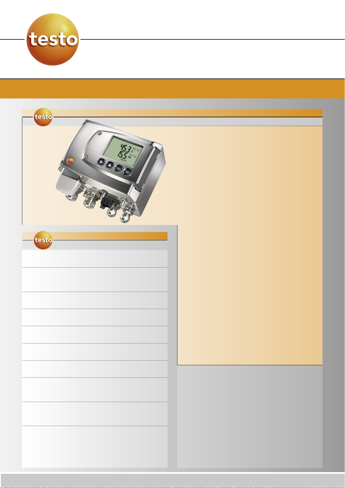
testo 6381
Differential pressure transmitter with humidity temperature option
The
testo 6381 was
developed specially for monitoring differential pressure
in the measuring range from 10 Pa to 1000 hPa. In
cleanroom technology, the maintenance of positive
pressure prevents the entry of contaminated air. In
order to keep the cleanroom conditions constant, the
transmitter additionally calculates the parameters
volume flow and flow velocity from the measured
differential pressure. Thanks to an optional probe from
the probe series 6610, the additional recording of
humidity and temperature with one instrument is also
possible.
The testo 6381 is particularly outstanding thanks to
SPECIFICATIONS
testo 6381
• Measurement of differential pressure, flow velocity,
volume flow; optional: humidity and temperature
• Automatic zero-point adjustment guarantees high,
temperature-independent accuracy and long-term
stability
the automatioc zero-point adjustment which ensures
high accuracy and long-term stability.
The integrated self-monitoring and early warning
function also the operator
uptime.
&
SPECIFICATIONS
differential pressure transmitter
ensures
maximum
testo 6381
Subject to change without notice.
• Low measurement range to 10 Pa ensures very
high precision at lowest pressures
• The robust metal housing protects tough
ambient conditions
• Display with multi-language operating menu and
optical alarm display
• Ethernet, relay and analog outputs allow optimum
integration into individual automation systems
• Self-monitoring of the transmitter and early warning
function
• P2A software for , adjustment
and analysis saves time and costs in commissioning
and maintenance
• Scalability of ±50 percent of the measuring range
final value and free scalability within the measuring
range
• Configurable alarm management with adjustable
response delay and alarm acknowledgement
.
ensure maximum uptime
programming
down
against
Typical applications:
• Differential pressure monitoring between
cleanrooms; optional: simultaneous measurement of
ambient temperature and humidity
• Monitoring drying processes
• Differential pressure measurement in filling
processes and spray-painting systems
tteessttoo
inc. 40 Whitel Lake Road Sparta, NJ 07871
www.testo.us
Page 2

Differential pressure transmitter with humidity/temperature option
Technical data
testo 6381
Parameters
ifferential pressure
D
easuring range 0 to 10 Pa
M
to 50 Pa
0
0 to 100 Pa
0 to 500 Pa
0 to 10 hPa
to 50 hPa
0
to 100 hPa
0
to 500 hPa
0
0 to 1000 hPa
10 to 10 Pa
50 to 50 Pa
-
-100 to 100 Pa
-500 to 500 Pa
-10 to 10 hPa
-50 to 50 hPa
100 to 100 hPa
-
-500 to 500 hPa
1000 to 1000 hPa
-
Measurement uncertainty* ±0,5% of measurement range final value
±0.3 Pa
Temperature gain drift: 0.02% of
measuring range per Kelvin deviaton
from nominal temperature 22 °C
Zero-point: 0% (thanks to cyclic zeropoint adjustment)
Selectable units Differential pressure in Pa, hPa, kPa,
mbar, bar, mmH
HG, inch H
alculated parameters: volume flow in
c
3
m
h, l/min, Nm
/
low velocity in m/s, ft/min
F
O, kg/cm2, PSI, inch
2
O
2
3
h, Nl/min
/
Sensor Piezoresistive sensor
Autom. Zero-point
adjustment
Overload
via magnetic valve
Frequency adjustable: 15 sec, 30 sec, 1
in, 5 min, 10 min
m
MMeeaassuurriinngg rraannggee OOvveerrllooaadd
0 ... 10 Pa 0,1 Pa
0 ... 50 Pa 0,1 Pa
0 ... 100 Pa 0,1 Pa
0 ... 500 Pa 0,1 Pa
0 ... 10 hPa 0,01 hPa
0 ... 50 hPa 0,01 hPa
0 ... 100 hPa 0,1 hPa
0 ... 500 hPa 0,1 hPa
0 ... 1000 hPa 1 hPa
-10 ... 10 Pa 0,1 Pa
-50 ... 50 Pa 0,1 Pa
-100 ... 100 Pa 0,1 Pa
-500 ... 500 Pa 0,1 Pa
-10 ... 10 hPa 0,01 hPa
-50 ... 50 hPa 0,01 hPa
-100 ... 100 hPa 0,1 hPa
-500 ... 500 hPa 0,1 hPa
-1000 ... 1000 hPa 1 hPa
Parameters
robe
P
Type
Parameters
MMeeaass.. rraannggee
Humidity /
race humidity
t
Temperature
MMeeaassuurreemmeennt
uunncceerrttaaiinnttyy*
*
Humidity
Dewpoint
Temp. at
+25°C /
+77°F
Inputs/outputs
umidity/temperature optional
H
testo 6612testo 6611 testo 6613 testo 6614 testo 6615 testo 6617
Wall
hannel Channel Duct
C
eated
h
able
C
race
t
humidity
Self-check
able with
C
over elec-
c
trode
monitoring
%RH / °C/°F / °C
/ °Fwb / kJ/kg / mbar / inch H
20 to +70 °C
4 to +158 °F
-
/ °Ftd/ g/kg / gr/lb / g/m3 / gr/ft³ / ppmV / °Cwb
td
0 to 100 %RH -60 to +30 °C
30 to +150 °C
-
-22 to +302 °F
O / °Ctm (H2O2)/°Ftm (H2O2) / % Vol
2
td
40 to +180 °C
-
-40 to +356 °F
-40 to +120 °C
-40 to +248 °F
0 to 100 %RH
-40 to +180 °C
-40 to +356 °F
t
testo 6611 testo 6612 testo 6613 testo 6614 testo 6615 testo 6617
1.0 %RH for 0 to 90 %RH /
±
±1.4 %RH for 90 to 100 % RH
±1.0 %RH for
0 to100 %RH
1.2 %RH for
±
0 to 90 %RH /
±1.6 %RH for
90 to 100 %RH
for deviations from media temp. ±25 °C:±0.02 %RH/K
±1 K at
0 °C td
±2 K at
-40 °C td
±4 K at
-50 °C td
±0,15 °C/
32,2 °F
Pt1000 1/3 Klasse B
±0.15 °C/
32.2 °F
Pt100 1/3
Class B
±0,15 °C/
32,2 °F
Pt1000 1/3
Klasse B
Analog outputs
Quantity Standard: 1;
with optional humidity probe: 3
Output type 0/4 to 20 mA (4-wire) (24 VAC/DC)
0 to 1/5 to 10 V (4-wire) (24 VAC/DC)
Scaling Differential pressure: scalable ±50% of
measuring range final value;
freely scalable within measuring range
* Measurement inaccuracy according to GUM.
FFoorr ddiiffffeerreennttiiaall pprreessssuurree::
FFoorr hhuummiiddiittyy::
Additional humidity-dependent inaccuracy contribution
±0.8% of measuring range final value ±0.3 Pa
+0.007 * MW (in %RH).
GGUUMM(GG
uide to the Expression of UUncertainty in MMeasurement):
ISO guideline for the determination of measurement inaccuracy, in order to make
measurements comparable worldwide.
The following inaccuracies are used for the determination:
- Hysteresis
- Linearity
- Reproducibility
- Long-term stability (only for differential pressure)
- Adjustment site/factory calibration
- Test site
Subject to change without notice.
tteessttoo
inc. 40 Whitel Lake Road Sparta, NJ 07871
Meas. cycle 1/sec
Resolution 12 bit
Max. load max. 500 Ω
Other outputs
Ethernet Optional
Relay Optional: 4 relays (free allocation to
measurement channels or as collective
alarm in operating menu/P2A), up to
250 VAC/3A (NO or NC)
Digital Mini-DIN for P2A software
Supply
Voltage supply 20 to 30 VAC/DC, 300 mA current
consumption, galvanically separate
signal and supply line
www.testo.us
Page 3

Differential pressure transmitter with humidity/temperature option
Technical drawingsTechnical data
General technical data
Model
aterial
M
Dimensions 162 x 122 x 77 mm
Weight 1.96 kg; optional: Ethernet intermediary
Display
Display optional: 3-line LCD with
Resolution
ifferential pressure
D
Humidity
Temperature
Miscellaneous
Protection class IP 65
EMC EU guideline 2004/108/EC
Metal housing
layer 0.61 kg
multi-language operating menu
MMeeaassuurriinngg rraannggee RReessoolluuttiioonn
0 to 10 Pa 0,1 Pa
0 to 50 Pa 0,1 Pa
0 to 100 Pa 0,1 Pa
0 to 500 Pa 0,1 Pa
0 to 10 hPa 0,01 hPa
to 50 hPa 0,01 hPa
0
0 to 100 hPa 0,1 hPa
0 to 500 hPa 0,1 hPa
0 to 1000 hPa 1 hPa
-10 to 10 Pa 0,1 Pa
-50 to 50 Pa 0,1 Pa
-100 to 100 Pa 0,1 Pa
-500 to 500 Pa 0,1 Pa
-10 to 10 hPa 0,01 hPa
-50 to 50 hPa 0,01 hPa
-100 to 100 hPa 0,1 hPa
500 to 500 hPa 0,1 hPa
-
-1000 to 1000 hPa 1 hPa
0,1 %RH
0,01 °C / 0,01 °F
02 mm
1
testo 6381
122 mm
Operating conditions
With /
display
Operation temperature
w/out
Storage temperature -20 to 60 °C / -4 to 140 °F
Process temperature -20 to +65 °C / -4 to +149 °F
-5 to 50 °C / 23 to 122 °F
162 mm
Power / Analog output connections
CH1
20-30 V
AC/DC
24V
-
+
+
CH2 CH3
-
+
-
-
+
+
0V
-
1
Subject to change without notice.
tteessttoo
inc. 40 Whitel Lake Road Sparta, NJ 07871
www.testo.us
Page 4

Differential pressure transmitter with humidity/temperature option
The following options can be specified for the testo 6381:
testo 6381
AXX Messbereich
AXX Measuring range
BXX Analogausgang / Versorgung
BXX Analog display/supply
XX Display
XX Display / menu language
C
C
XX Gehäusefarbe
XX Cable input
E
D
XX Einheit
XX Ethernet
F
E
KXX Sprache der Bedienungsanleitung
FXX Differential pressure/flow velocity unit (pre-
(für zweisprachige Papier-Bedienungs -
set)
nleitung)
a
GXX opt. Analog output for humidity probe
connection (probe series
testo 6610) units (pre-set)
HXX Relay
IXX Units channel 3 pre-set (only if opt.
humidity probe connection available)
KXX Instruction manual language
NOTE: please ensure each testo 6381 Transmitter
has at least one Series 6610 digital probe specified for it
Probe Series 6610... Reqquired, not an option
XX
L
0555 6610 Lxx Mxx
Probe 6611 Wall -4 to +158 F (-20 to +70 C)
L11
Probe 6612 Duct -22 to +302 F (-30 to +150 C)
L12
Probe 6613 Cable -40 to +356 F (-40 to +180 C)
L13
Probe 6614 Heated probe -40 to +356 F (-40 to +180 F)
L14
Probe 6615 Trace humidity -60 to +100
L15
Probe 6617 Self-check -40 to +356 F (-40 to +180 C)
L17
Probe 6611 Wall High Accuracy -40 to +356 F (-40 to+180 C)
L11H
Probe 6613 Cable High Accuracy -40 to +356 F (-40 to+180 C)
L13H
Sintered stainless steel filter
M01
Wire mesh protective cap
M02
Sintered Teflon filter
M03
Metal protective cap, open
M04
Plastic protective cap ABS, open
M05
Teflon filter with drip hole
M06
Teflon filter with drip hole and condensation protection
M07
Filter for H
M08
Probe length 2.7" in (70 mm)
P07
Probe length 5.5 in (140 mm)
P14
Probe length 7.9 in (200 mm)
P20
P30
Probe length 11.8 in (300 mm)
P50
Probe length 19.7 in (500 mm)
P80
Probe length 31.5 in (800 mm)
N00
N01
N02
N05
N10
N23
2O2
No cable
Cable length 3.3 'ft (1 m) for probes 6613, 6614, 6615, 6617
Cable length 6.6 ft (2 m) for probes 6613, 6614, 6615, 6617
Cable length 16.4 ft (5 m) for probes 6613, 6614, 6615, 6617
Cable length 32.8 ft (10 m) for probes 6613, 6614, 6615, 6617
Cable length <<less than 1 m for duct version probe 6612 only
Nxx Pxx
tpd
environments
L11 L12 L13 L14 L15 L17 L11H &&%& L13H
X–––––
––X–––
XXXXXXX
–XX–––
–XXXXX
–XX–––
AXX Me asu ring ra ng e
A0 1 0 to 10 Pa
A0 2 0 to 50 Pa
A0 3 0 to 10 0 P a
04 0 to 5 00 Pa
A
05 0 to 1 0 hPa
A
07 0 to 5 0 hPa
A
A0 8 0 to 10 0 h Pa
A0 9 0 to 50 0 h Pa
A1 0 0 to 10 00 hP a
A2 1 -1 0 t o 10 Pa
22 -5 0 to 5 0 Pa
A
23 -1 00 t o 10 0 P a
A
A2 4 -5 00 to 5 00 P a
A2 5 -1 0 t o 10 hP a
A2 7 -5 0 t o 50 hP a
A2 8 -1 00 to 1 00 hP a
A2 9 -5 00 to 5 00 hP a
A3 0 -1 000 to 1 00 0 h P a
B XX Ana log d isp la y/su pp ly
B02 0 to 1 V (4- wi re, 2 4 VAC /D C)
B03 0 to 5 V (4 -w ire, 24 VA C/ D C)
B04 0 to 1 0 V (4- w ire , 2 4 V AC /DC )
B05 0 to 2 0 m A (4- w ire , 2 4 V AC /DC )
B06 4 to 2 0 m A (4- w ire , 2 4 V AC /DC )
C XX D isp lay / m enu la ng uag e
C 00 w itho ut dis pla y
C 02 w ith disp lay/E ng lis h
C 03 w ith disp lay/G er m an
C 04 w ith disp lay/Fr en ch
C 05 w ith disp lay/S pa ni sh
C 06 w ith disp lay/Ita lian
C 07 w ith disp lay/Ja pan ese
C 08 w ith disp lay/S we dish
D XX C ab le i np ut
D01 C ab le in pu t M 16 (re la y: M2 0)
D02 C ab le en try NPT 1/ 2“
D03 C ab le co nta ct v ia M-p lug c on nec tio n f or s ign al
an d s up ply
EX X Et he rn et
E0 0 w itho ut E the rn et m od ule
E0 1 w ith Et he rne t m od ul e
FX X D iffe ren tia l p res sur e/ flo w v elo ci ty u ni t
F0 1 Pa / m in / m ax
F0 2 hPa / m in / m ax
F0 3 kPa / m in / max
F0 4 mb ar / min / m ax
F0 5 bar / min / m ax
F0 6 mm H2O / min / m ax
F0 7 mm H
F0 8 inch HG / m in / ma x
F0 9 kg/ cm2/ m in / m ax
F1 0 PSI / m in / m ax
F1 1 m/s / m in / max
F1 2 ft/m in / m in / m ax
F1 3 m3/h / m in / m ax
F1 4 l/min / m in / ma x
F1 5 Nm
F1 6 Nl/m in / m in / m ax
O / min / m ax
2
3
/h / m in / m ax
–
–
–
–
L11 L12 L13 L14 L15 L17
X–––––
–– XXXX
–– XXXX
–– XXXX
–– XXXX
–X––––
Scaling: 50% of
measuring range
final value; freely
selectable within
measuring range
–
––
X
–
–
–
G XX op t. A na log o utp ut f or h um id ity p rob e
co nne ctio n ( pr ob e s erie s tes to 6 610 ) unit s
(p re -s et )
G 00 w ith out c on nec tion p oss ib ilit y for h um idity p ro be
te sto 66 10
G 01 % RH /M in/ M ax
G 02 °C /M in/M ax
G 03 °F /Min/ M ax
G 04 °C td / m in / m ax
G 05 °F td / m in / m ax
G 06 g /k g / m in / m ax
G 07 g r/l b /M in/M ax
08 g /m ³ / m in / m ax
G
G 09 g r/f t³ / m in / m ax
G 10 p pm V / m in / m ax
G 11 °C wb / m in / max
G 12 °F wb / m in / m ax
G 13 k J/kg / m in / m ax (e nth alp y)
G 14 m bar / m in / m ax (w ate r va po ur pa rtial p re ss ure)
15 in ch H
G
G 16 °C tm / m in / m ax (m ixtu re de w po in t for H
G 17 °F tm / m in / m ax (m ixtu re de w po in t f or H
G 18 % Vo l
H XX R ela y
H 00 w itho ut rel ay
01 4 re lay ou tp ut s, lim it va lue m on ito ring
H
H 02 4 rel ay o ut pu ts, ch ann el 1 lim it v alue s an d
IX X U nit s ch ann el 3 (p re -s et , o nly if o pt. h um idi ty
I0 1 % R H/ M in/ M ax
I0 2 ° C/ M in/ M ax
I0 3 ° F/ Mi n/ M ax
I0 4 ° Ct d/ M in/ M ax
I0 5 ° Ftd/Mi n/ M ax
I0 6 g /k g / m in / m ax
I0 7 g r/l b /M in/M ax
I0 8 g /m ³ / min / m ax
I0 9 g r/f t³ / m in / m ax
I1 0 p pm V / min / m ax
I1 1 ° Cw b / m in / m ax
I1 2 ° Fw b / m in / ma x
I1 3 k J/ kg / m in / ma x (en th alp y)
I1 4 m bar / m in / ma x (w ate r va pou r p ar tia l p res su re)
I1 5 in ch H
I1 6 ° Ct m / m in / m ax (m ixtu re de w po in t f or H
I1 7 ° Ftm / m in / m ax (mi xtu re d ew po int fo r H
I1 8 % Vo l
KXX In stru ctio n m an ua l la ngu age
K0 1 G er ma n/E ng lish in stru ctio n m anu al
K0 2 Fr en ch /En gl ish ins truc tion m an ua l
K0 3 Sp ani sh /E ng lish in stru ctio n m anu al
K0 4 Ita lian /E ng lish in stru ctio n manu al
K0 5 D utc h/E ng lish in stru ctio n m anu al
K0 6 Ja pan ese /E ng lish in stru ctio n ma nu al
K0 7 C hin ese /E ng lish in stru ctio n m anu al
K0 8 Sw ed ish /En gl ish ins truc tion m an ua l
/ m in / m ax (w ate r va pou r p ar tia l
O
2
re ss ure )
p
co llec tiv e al arm
pr ob e c onn ect io n av aila ble )
O / min / m ax (w ate r va pou r p ar tia l
2
pr es su re )
High Accuracy
Wall
Cable
L11H L13H
X
–
–
–
–
–
ith connection possibility
w
only possible when G-Code
(from ) selected
–
X
–
–
–
–
GXX
esto 6610
t
2O2
2O2
2O2
2O2
)
)
)
)
DS 6381 EN/msp/A/23.09.2009
 Loading...