

Testo 6381 Operating Manual
testo 6381 Ethernet · differential pressure transmitter
testo 6610 · Probes
P2A software · Parameterizing, adjusting and analyzing
software
Instruction manual

2

1 Safety and the environment
Pos: 1 /TD/Überschriften/MUF/Sicherheit und Umwel t @ 3\mod_1234793958627_7 9.doc @ 26223 @ 1
1 Safety and the environment
Pos: 2 /TD/Sicherheit und Umwelt/Sicherheit gewähr leisten/MUF 63xx/Elek trische Gefahren ver meiden @ 3\mod_12347946092 99_79.doc @ 26280 @ 5
Avoiding electrical hazards
> Never use the instrument and connected probes to measure on
or near live parts!
> Damaged mains cables must only be replaced by authorized
personnel.
> Only have the transmitter wired and connected by authorized
personnel with the voltage disconnected.
> You must always comply with the regulations applicable in your
Pos: 3 /TD/Sicherheit und Umwelt/Sicherheit gewähr leisten/MUF 63xx/Per sonen- und Sachschäden ver meiden @ 3\mod_1234794744 768_79.doc @ 26299 @ 5
country for opening and repairing electrical equipment.
Avoiding personal injury and damage to equipment
> Installation, setting and calibration work must only be carried
out by qualified and authorized personnel!
> Only open the instrument when this is expressly described in
the instruction manual for installation, maintenance or repair
purposes.
> Observe the permissible storage, transport and operating
Pos: 4 /TD/Sicherheit und Umwelt/Sicherheit gewähr leisten/Nicht mit Lös ungsmitteln lagern @ 0\ mod_1175692375179_79.d oc @ 583 @
temperature.
> Do not store the product together with solvents. Do not use any
Pos: 5 /TD/Sicherheit und Umwelt/Sicherheit gewähr leisten/MUF 63xx/Bei W artung MUF nicht zur Regelun g verwenden @ 3\mod_123479 4852377_79.doc @ 26318 @
desiccants.
> Do not use the instrument for control purposes at the same time
Pos: 6 /TD/Sicherheit und Umwelt/Sicherheit gewähr leisten/Produkt besti mmungsgemäß verwenden @ 0\mod_1173781261848 _79.doc @ 386 @
as operating or servicing the transmitter.
> Only operate the product properly, for its intended purpose and
within the parameters specified in the technical data. Do not
Pos: 7 /TD/Sicherheit und Umwelt/Sicherheit gewähr leisten/Nur beschri ebene Wartungsarbeite n durchführen @ 0\mod_11756 92705195_79.doc @ 601 @
use any force.
> Carry out only the maintenance and repair work on this
instrument that is described in the documentation. Follow the
prescribed steps exactly. Use only original spare parts from
Pos: 8 /TD/Sicherheit und Umwelt/Sicherheit gewähr leisten/MUF 63xx/Fac hpersonal @ 3\mod_12347949 40409_79.doc @ 26337 @
Testo.
Any additional work must only be carried out by authorized
personnel. Otherwise testo will not accept any responsibility for the
proper functioning of the instrument after repair and for the validity
of certifications.
3
2 About this document
Pos: 9 /TD/Überschriften/MUF/Umwelt schützen @ 3\mod_ 1234858757571_79. doc @ 26363 @ 5
Pos: 10 /TD/Sicherheit und Umwelt/Umwelt schützen/Pr odukt entsorgen @ 0\mod_ 1173780307072_79.doc @ 357 @
Protecting the environment
> At the end of its useful life, send the product to the separate
collection for electric and electronic devices (observe local
Pos: 11 /TD/Überschriften/MUF/Zu diesem Dokument @ 3\mod_ 1234793991331_79. doc @ 26242 @ 1
2 About this document
Pos: 12 /TD/Sicherheit und Umwelt/Zu diesem Dokument/Ver wendung (Standard) @ 0\mod_1173775068554_79. doc @ 337 @ 5
regulations) or return the product to Testo for disposal.
Use
> Please read this documentation through carefully and
familiarize yourself with the product before putting it to use. Pay
particular attention to the safety instructions and warning advice
in order to prevent injuries and damage to the products.
> Keep this document to hand so that you can refer to it when
necessary.
> Hand this documentation on to any subsequent users of the
Pos: 13 /TD/Sicherheit und Umwelt/Zu diesem Dokument/Sy mbole und Schreibkonven tionen/War nhinweis WARNUNG @ 2\mod_12076469662 34_79.doc @ 14398 @
Pos: 14 /TD/Sicherheit und Umwelt/Zu diesem Dokument/Sy mbole und Schreibkonven tionen/War nhinweis VORSICHT @ 2\mod_1207651 416515_79.doc @ 14416 @
Pos: 15 /TD/Sicherheit und Umwelt/Zu diesem Dokument/Sy mbole und Schreibkonv. Sof tware [Standard] @ 0\mod_1190203332543_79. doc @ 4883 @ 5
product.
WARNING
CAUTION
Indicates potential serious injuries
indicates potential minor injuries
Symbols and writing standards
Representa-
Explanation
tion
Note: Basic or further information.
1. ...
2. ...
Action: more steps, the sequence must be
followed.
> ... Action: a step or an optional step.
- ... Result of an action.
Menu
[OK]
Elements of the program interface.
Buttons of the program interface.
... | ... Functions/paths within a menu.
“...” Example entries
Pos: 16 /TD/--- Seitenwechsel --- @ 0\mod_1173774430601_0.doc @ 283 @
4

3 Contents
Pos: 17 /TD/Überschriften/MUF/Inhalt @ 3\mod_123479 4019831_79.doc @ 26261 @ 1
3 Contents
1 Safety and the environment....................................................................3
2 About this document...............................................................................4
3 Contents...................................................................................................5
4 Transmitter...............................................................................................9
4.1. Specifications ..................................................................................9
4.1.1. Functions and use ...........................................................................................9
4.1.2. Scope of delivery .............................................................................................9
4.1.3. Accessories ...................................................................................................10
4.1.4. Technical data ...............................................................................................10
4.1.5. Dimensions ....................................................................................................14
4.2. Product description........................................................................15
4.2.1. At a glance..................................................................................................... 15
4.2.2. Usable probes................................................................................................ 16
4.2.3. Display and keypad........................................................................................17
4.2.4. Service interface ............................................................................................17
4.2.5. Relay board (option) ......................................................................................17
4.2.6. Analog outputs...............................................................................................18
4.2.7. Parameters ....................................................................................................18
4.2.8. Scaling 19
4.2.9. Alarm handling...............................................................................................22
4.3. Commissioning ..............................................................................23
4.3.1. Inserting Ethernet module (order no. 0554 6656)...........................................23
4.3.2. Assembling the instrument............................................................................. 25
4.3.2.1. Wall mounting (for testo 6611, 6613, 6614, 6615, 6617 probes)....... 25
4.3.2.2. Duct mounting (for testo 6612 probes).............................................. 26
4.3.3. Connecting the instrument .............................................................................27
4.3.3.1. Overview of terminals........................................................................29
4.3.3.2. Connecting voltage supply and analog outputs.................................30
4.3.3.3. Connecting the relay outputs ............................................................31
4.3.3.4. Plug-in connection option..................................................................34
4.3.3.5. Creating the PE/earthing terminal .....................................................35
4.3.3.6. Setting the Ethernet module..............................................................36
4.3.3.7. Closing the instrument ......................................................................38
4.3.4. Ethernet communication ................................................................................39
4.3.4.1. Types of operation............................................................................39
4.3.4.2. Mains connection.............................................................................. 39
4.3.4.3. LED status displays ..........................................................................40
4.3.4.4. testo 6381 as Saveris subscriber ......................................................40
4.3.4.5. Integration into customer's Ethernet system......................................41
4.3.4.6. Adjusting the instrument....................................................................51
4.3.4.7. Overview: Adjustment keys and test contacts................................... 52
5

3 Contents
4.3.4.8. 1-point adjustment (offset - humidity/temperature)............................ 53
4.3.4.9. 2-point adjustment (humidity/temperature)........................................ 55
4.3.4.10. Analog output adjustment ..........................................................57
4.3.4.11. n-point adjustment (pressure) .................................................... 58
4.3.4.12. High-humidity adjustment for testo 6614.................................... 59
4.3.4.13. Self adjustment of testo 6615 trace humidity probe....................60
4.4. Operation ...................................................................................... 62
4.4.1. Relationship between user menu and mini-DIN socket is active....................62
4.4.2. Key cover ...................................................................................................... 62
4.4.3. Password protection ......................................................................................63
4.4.4. Structure of user menu ..................................................................................63
4.4.5. Overview of the testo 6381 user menu ..........................................................65
4.4.6. The individual main menus ............................................................................68
4.4.6.1. Editing main menu of channel 1........................................................68
4.4.6.2. Editing Main Menu Channel 2 (if this option is available) ..................68
4.4.6.3. Editing Main Menu Channel 3 (if this option is available) ..................69
4.4.6.4. Editing Main Menu Alarm.................................................................. 69
4.4.6.5. Editing Main Menu Settings ..............................................................71
4.4.6.6. Editing Main Menu Analysis.............................................................. 75
4.4.6.7. Editing Message main menu.............................................................76
4.4.6.8. Calling up Main Menu Ident..............................................................78
4.4.6.9. Editing Main Menu Adjust.................................................................78
4.4.6.10. Editing Reset main menu........................................................... 81
4.5. Status, warning and error messages ............................................ 81
4.5.1. Status messages ...........................................................................................82
4.5.2. Warning messages ........................................................................................83
4.5.3. Transmitter error messages........................................................................... 85
4.5.4. Handling alarm messages .............................................................................86
4.5.5. Namur fault conditions ...................................................................................88
4.6. Maintenance and cleaning ............................................................ 89
4.6.1. Maintaining the instrument............................................................................. 89
4.6.2. Cleaning the instrument.................................................................................89
5 testo 6610 probes..................................................................................90
5.1. Specifications................................................................................90
5.1.1. Functions and use .........................................................................................90
5.1.1.1. Digital probes:................................................................................... 90
5.1.1.2. The Testo humidity sensor................................................................90
5.1.1.3. Self-diagnosis...................................................................................91
5.1.2. Design of the probe .......................................................................................92
5.1.3. Accessories ...................................................................................................92
5.2. Product description .......................................................................93
5.2.1. Overview of probe and filter types.................................................................. 93
5.2.1.1. Probe version....................................................................................93
5.2.1.2. Determining the accuracy/measuring uncertainty .............................93
5.2.1.3. Ordering options for testo 6610 probe (0555 6610)...........................94
5.2.1.4. Protection caps................................................................................. 96
6

3 Contents
5.2.2. testo 6611 wall probe..................................................................................... 96
5.2.3. testo 6612 duct probe ....................................................................................99
5.2.4. testo 6613 cable probe ................................................................................103
5.2.5. testo 6614 heated cable probe.....................................................................106
5.2.6. testo 6617 cable probe (self-monitoring)...................................................... 113
5.2.6.1. Self-monitoring of cover electrode...................................................114
5.3. Commissioning ............................................................................117
5.3.1. Installing the probe ......................................................................................117
5.3.1.1. Installing the testo 6611 wall probe................................................. 117
5.3.1.2. 2.3.1.2 Installing the testo 6612 duct probe..................................... 117
5.3.1.3. 2.3.1.3 Installing testo 6613/6614/6615/6617 probes...................... 117
5.3.2. Connecting/removing the probe to/from the transmitter................................122
5.4. Maintenance and cleaning...........................................................122
5.4.1. Replacing filters/protection caps ..................................................................122
5.4.1.1. Replacing the filter/protection caps for testo 6611 wall version.......122
5.4.1.2. Replacing the filter/protection cap for testo 6612 duct version ........123
5.4.1.3. Replacing the filter/protection cap for duct versions........................ 124
5.4.2. Cleaning the instrument and filter/protection cap .........................................124
5.4.3. Replacing the sensor ...................................................................................124
6 Parameterizing, adjusting and analyzing software (P2A software).125
6.1. Specifications ..............................................................................125
6.1.1. Functions and use .......................................................................................125
6.1.2. System requirements...................................................................................126
6.1.3. Scope of delivery .........................................................................................126
6.2. First steps....................................................................................127
6.2.1. Installing the software/driver ........................................................................127
6.2.1.1. Installing P2A software....................................................................127
6.2.1.2. Installing USB driver .......................................................................127
6.2.1.3. P2A software upgrade ....................................................................127
6.2.2. Starting the software....................................................................................127
6.2.2.1. Starting the program.......................................................................127
6.2.2.2. Establishing a connection with the instrument.................................127
6.2.2.3. Activating the connection with the instrument..................................128
6.3. Using the software.......................................................................128
6.3.1. User interface ..............................................................................................128
6.3.2. Editing instrument/parameter file .................................................................131
6.3.2.1. Changing instrument/parameter file................................................131
6.3.2.2. Creating a new instrument file.........................................................140
6.3.2.3. Saving parameters..........................................................................140
6.3.2.4. Opening the parameter file..............................................................141
6.3.2.5. Copying and pasting parameters ....................................................141
6.3.2.6. Deleting instrument/parameter file ..................................................142
6.3.3. Analyzing/testing the transmitter ..................................................................142
6.3.3.1. Analyzing/testing the instrument .....................................................142
6.3.3.2. Carrying out factory reset................................................................ 143
6.3.3.3. Testing analog output .....................................................................143
7

3 Contents
6.3.3.4. Testing switch output relays 1 to 4.................................................. 145
6.3.3.5. Displaying min./max. values............................................................146
6.3.4. Adjusting the transmitter ..............................................................................149
6.3.4.1. 1-point adjustment ..........................................................................149
6.3.4.2. 2-point adjustment ..........................................................................151
6.3.4.3. n-point adjustment ..........................................................................152
6.3.4.4. Adjusting the analog output ............................................................153
6.3.5. Transmitter history.......................................................................................154
7 Tips and assistance............................................................................159
7.1. Questions and answers .............................................................. 159
7.2. Accessories and spare parts....................................................... 159
7.2.1. Ordering options for 6381 transmitter (0555 6381) ......................................162
7.2.2. Ordering options for testo 6610 probes (0555 6610)....................................166
Pos: 18 /TD/--- Seitenwechsel --- @ 0\mod_1173774430601_0.doc @ 283 @
8

Pos: 19 /TD/Überschriften/MUF/1 Messumformer @ 3\ mod_1234258401060_79.doc @ 23894 @ 1
4 Transmitter
Pos: 20 /TD/Überschriften/MUF/1.1/2.1/3.1 Leis tungsbeschreibung @ 3\ mod_1234258595211_79. doc @ 23951 @ 2
4.1. Specifications
Pos: 21 /TD/Leistungsbeschreibung/Verwendung/ MUF63xx/MUF 638x Ethernet @ 3\ mod_1234443770405_79. doc @ 25020 @ 3
4.1.1. Functions and use
The testo 6381 transmitter with Ethernet module is used together
with the plug-in, adjusted probes from the testo 6610 family.
Please refer to volume 2, testo 6610 probes, page 90 for
information about commissioning, operating and maintaining the
testo 6610 probe.
The testo 6381 transmitter is suitable for the following applications
with Ethernet networking, amongst others:
• Clean rooms
• Test benches
• Drying processes
• Filling processes
• Painting systems
• Monitoring flow velocities or volumetric flow rates in air
conditioning systems
In addition to the signal transmission of the readings to a control
unit via analog outputs, the measurement data can simultaneously
be recorded, documented and visualized via Ethernet.
Furthermore, it is possible to issue an alarm for those responsible
Pos: 22 /TD/Leistungsbeschreibung/Lieferu mfang/MUF 63xx/MUF 63xx Ether net @ 3\mod_12344473084 72_79.doc @ 25117 @ 3
for the process, if necessary.
4 Transmitter
4.1.2. Scope of delivery
The scope of delivery of the testo 6381 transmitter includes the
following:
• Key cover
• Rear panel bracket
• Ethernet module
• Instruction manual
• Calibration report
• CD-ROM with operating instructions (PDF), configuration files
for Ethernet module and P2A update (this can only be used in
conjunction with the P2A software, which has to be ordered
separately).
9

4 Transmitter
Pos: 23 /TD/Leistungsbeschreibung/Lieferu mfang/MUF 63xx/Zubehör Übersicht 638x @ 3\mod_123444 8071530_79.doc @ 25136 @ 3
4.1.3. Accessories
The following accessories are available for the testo 6381
transmitter, amongst others:
• Protection caps for probes
• Mains unit
• P2A software (parameterizing, adjusting and analyzing
software)
• Assembly accessories
Information about accessories and their order numbers can
be found in volume 2, Accessories and spare parts or on
Pos: 24 /TD/Leistungsbeschreibung/Technische Dat en/MUF 63xx/MUF 638 x Ethernet @ 3\mod_12344482961 23_79.doc @ 25156 @ 35555555 55555555555555555
the website at www.testo.com.
4.1.4. Technical data
Parameters
• Differential pressure
• Humidity (various variables and units)
• Temperature (°C/°F)
Differential pressure accuracy
The specifications are only valid if the positive pressure is
applied at the positive pressure connection.
• 0.5 % of measuring range, additional 0.3 Pa intrinsic error 1
• T
K slope drift
= 0.03 % of measuring range per degree Kelvin of
deviation from nominal temperature 22 °C
• T
K zeroing drift
= 0 %, as zeroing with solenoid valve2
1
Measuring uncertainty in accordance with GUM: ±0.8 % of measuring range
final value ±0.3 Pa.
GUM (Guide to the Expression of Uncertainty in Measurement): ISO guideline for determining the
measuring uncertainty in order to render global measurement results comparable.
The following uncertainties are used during the inquiry:
• Hysteresis
• Linearity
• Reproducibility
• Adjustment area/factory calibration
• Test location
10

4 Transmitter
Humidity and temperature accuracy
• Depends on probe
Pressure measuring range, resolution and overload of
differential pressure
Pressure
Resolution Overload
measuring range
depending on
version ordered
0 to 50 Pa 0.1 Pa 20,000 Pa
0 to 50 Pa 0.1 Pa 20,000 Pa
0 to 100 Pa 0.1 Pa 20,000 Pa
0 to 500 Pa 0.1 Pa 20,000 Pa
0 to 10 hPa 0.01 hPa 200 hPa
0 to 50 hPa 0.01 hPa 750 hPa
0 to 100 hPa 0.1 hPa 750 hPa
0 to 500 hPa 0.1 hPa 2500 hPa
0 to 1000 hPa 1 hPa 2500 hPa
-10 to 10 Pa 0.1 Pa 20,000 Pa
-50 to 50 Pa 0.1 Pa 20,000 Pa
-100 to 100 Pa 0.1 Pa 20,000 Pa
-500 to 500 Pa 0.1 Pa 20,000 Pa
-10 to 10 hPa 0.01 hPa 200 hPa
-50 to 50 hPa 0.01 hPa 750 hPa
-100 to 100 hPa 0.1 hPa 750 hPa
-500 to 500 hPa 0.1 hPa 2500 hPa
-1000 to 1000 hPa 1 hPa 2500 hPa
Upon delivery and following a factory reset the readings are
shown in the display in the unit that was ordered via the
KMAT option Fxx, see Ordering options for 6381 transmitter
(0555 6381), page 162.
Humidity and temperature measuring range
• Depends on probe
2
Minor mixtures of the media may occur at the positive and negative pressure
side due to the automatic zeroing cycle.
11
4 Transmitter
Humidity and temperature resolution
• 0.1 % RH or 0.01 °C/0.01 °F
Meas. cycle
• 1/sec
Interface
• Mini-DIN for P2A software (parameterizing and adjusting
software) and handheld testo 400/650
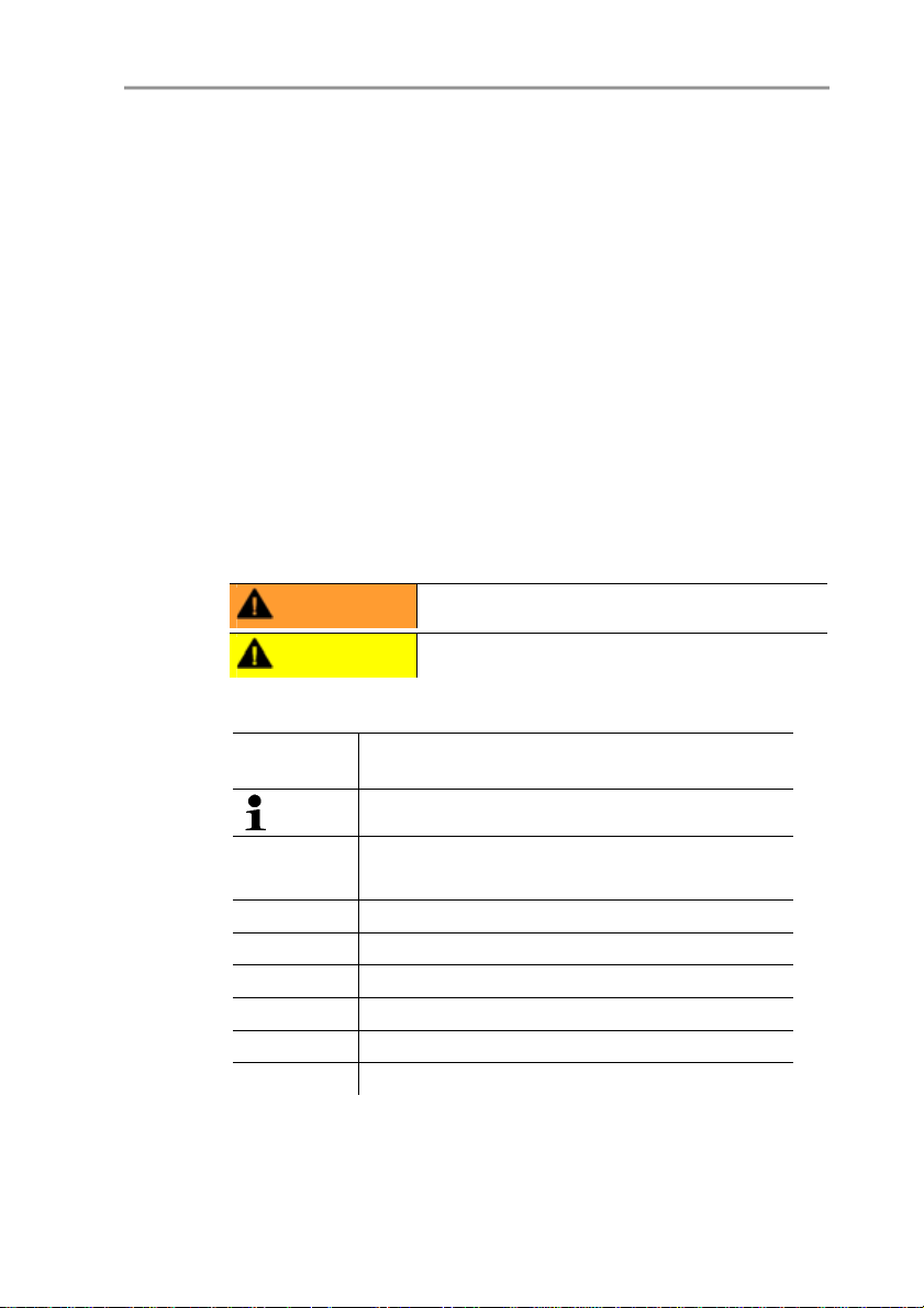
Voltage supply
• 4-wire (separate signal and supply lines): 20 to 30 V AC/DC,
300 mA power consumption
Maximum load
• 4-wire: 500 Ω (power output)
12
Maximal load
• 4-wire: 10 kΩ (voltage output)
Analog output
• 0 to 1 V ± 1.5 mV (4-wire) or
• 0 to 5 V ± 7.5 mV (4-wire) or
• 0 to 10 V ± 15 mV (4-wire) or
• 0 to 20 mA ± 0.03 mA (4-wire) or

• 4 to 20 mA ± 0.03 mA (4-wire)
Resolution of analog output
• 12 bit
Relay
• 4 relays, 250 V AC/DC, 3 A (optional)
Display
• 2-line LCD with plain text line (optional)
Operating temperature
• -5 to 50 °C/23 to 122 °F
Storage temperature
• -20 to 60 °C/-4 to +140 °F
Process temperature
• -20 to 65 °C/-4 to 149 °F
Oper. humidity
• 0 to 90 % RH
4 Transmitter
Housing, weight
• Metal: 1.960 kg
• Ethernet module: 0.610 kg
Protection class
• IP 65 only if the transmitter is wired properly (closed cable
entries), Ethernet connector, Harting PushPull connector and
humidity probe are inserted and/or sealing plugs are inserted.
Directives, standards and tests
• EC Directive: 2004/108/EC
• DIN 14644-4
• EN 61000-6-2 interference immunity
• EN 61000-6-3 interference emission
• EN 61326-1+A1+A2
13
4 Transmitter
Ethernet module
• Interface:
◦ 1 x mini-DIN
◦ 1 x RJ45 (Ethernet 10 BaseT/100 BaseTX)
• LED:
2 x green
Warranty
• Duration: 2 years
Pos: 25 /TD/Leistungsbeschreibung/Technische Dat en/MUF 63xx/MUF 63xx Ab messungen @ 3\mod_123445067 1494_79.doc @ 25194 @ 3
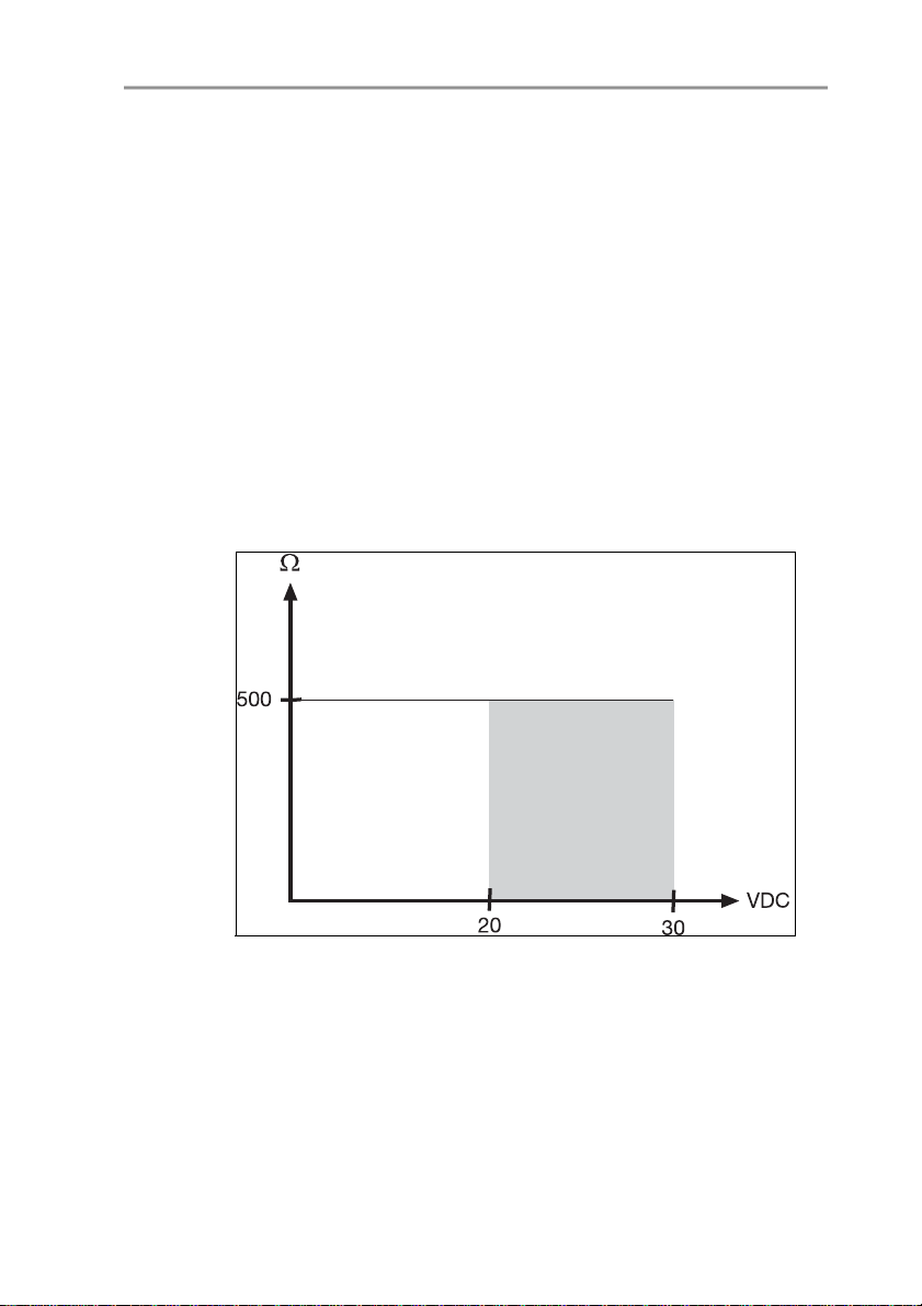
4.1.5. Dimensions
• Warranty conditions: see website www.testo.com/warranty
Pos: 26 /TD/Überschriften/MUF/1.2/2.2 Produktb eschreibung @ 3\mod_12342 58723551_79.doc @ 24008 @ 2
14
Dimensions in mm a b
with M20 cable couplings 144 147
With NPT cable coupling 144 144
With M plug-in connection 143
4.2. Product description
Pos: 27 /TD/Produktbeschreibung/Übersicht/ MUF 63xx/Auf einen Blick MUF 638 x Ethernet @ 3\mod_1234772 621147_79.doc @ 25612 @ 3
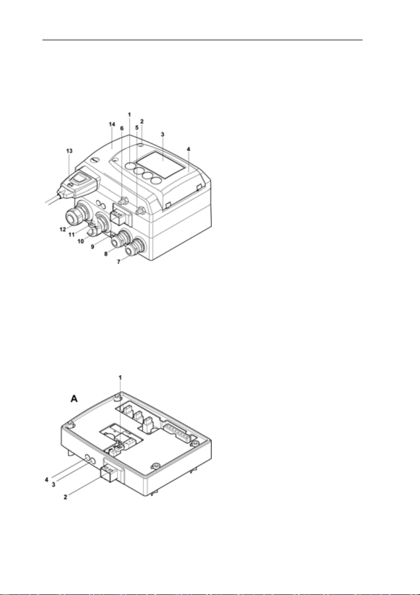
4.2.1. At a glance
1 Keys (only with optional display)
2 Service flap screw connection
(self-locking, 2 pcs.)
3 Display (optional)
4 Service flap
5 Negative pressure connection
6 Positive pressure connection,
marked with a red washer
7 M 16 x 1.5 screw connection*,
e.g. analog outputs
8 M 16 x 1.5 screw connection*,
e.g. voltage supply
9 Earthing/PE connection
10 M 20 x 1.5 screw connection*,
e.g. R3 and R4 relays
11 Eyelet for measuring point panel
12 M 20 x 1.5 screw connection*,
e.g. R1 and R2 relays
13 Probe connector (testo 6610)
14 Upper part of housing
* Alternatively, NPT cable
couplings or M plug-in
connections are available
A Ethernet module
1 DIP switch
2 Ethernet port
3 LED: LAN connection status
4 LED: Supply
4 Transmitter
15
4 Transmitter
Pos: 28 /TD/Produktbeschreibung/Übersicht/ MUF 63xx/Verwendbare Füh ler 638x @ 3\mod_1234773201901 _79.doc @ 25631 @ 3
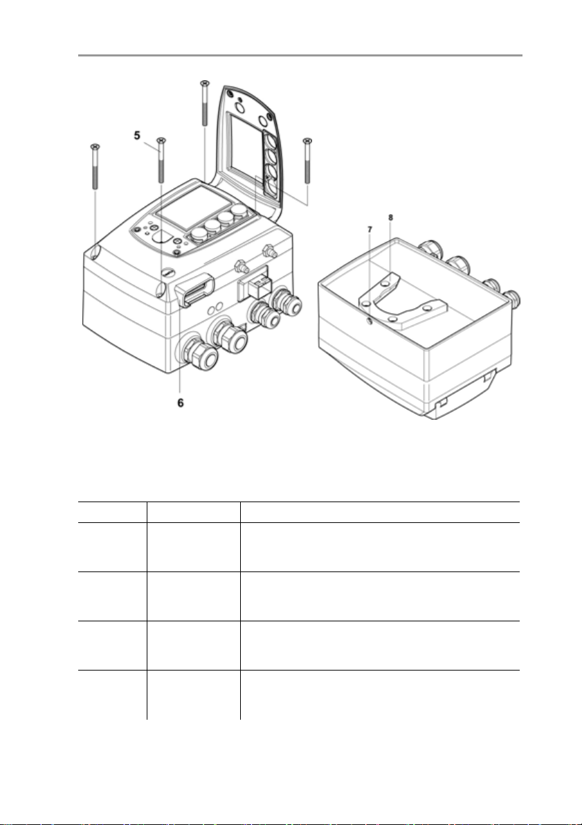
5 Housing screws
6 Socket for probe connector
7 Hole for fastening to rear panel
bracket (M3 x 6 screw)
8 Plastic bracket for assembly on
rear panel
4.2.2. Usable probes
Probes Article no. Characteristic
testo 6611 0555 6610-L11
testo 6612 0555 6610-L12
testo 6613 0555 6610-L13
testo 6614 0555 6610-L14
16
The testo 6381 transmitter can be used with the following probes:
Wall probe version; accuracy to ±1 % RH;
temperature range -20 to +70 °C/-4 to +158 °F,
sensor plugged in
Duct probe version; accuracy to ±1 % RH;
temperature range -30 to +150 °C/
-22 to +302 °F, sensor soldered
Cable probe version; accuracy to ±1 % RH;
temperature range -40 to +180 °C/
-40 to +356 °F, sensor soldered
Heated cable probe version; accuracy to ±1.0 %
RH; temperature range -40 to +180 °C/
-40 to +356 °F, sensor soldered

Probes Article no. Characteristic
testo 6615 0555 6610-L15
Trace humidity cable probe version; accuracy
±1 K at 0 °Ctd/+32 °Ftd; temperature range
-40 to 120 °C/-40 to +248 °F, sensor soldered
testo 6617 0555 6610-L17
Cable with cover electrode monitoring probe
version; accuracy to ± 1.2 % RH; temperature
range -40 to 180 °C/
-40 to +356 °F, sensor soldered
Pos: 29 /TD/Produktbeschreibung/Übersicht/ MUF 63xx/Display und Tastat ur @ 3\mod_1234773965059 _79.doc @ 25650 @ 3
4.2.3. Display and keypad
The display option allows operation of the testo 6381 transmitter via
the display and four keys.
The LCD display consists of two 7-segment lines for displaying
readings and units and of an information line (for status messages,
for example).
The brightness and contrast of the display and the background
lighting (permanent or off) can be changed via the user menu or the
Pos: 30 /TD/Überschriften/MUF/1.2.x Servicesc hnittstelle @ 3\mod_1237 306891654_79.doc @ 29795 @ 3
4.2.4. Service interface
Pos: 31 /TD/Produktbeschreibung/Übersicht/ MUF 63xx/Serviceschni ttstelle 638x @ 3\mod_123 4774092911_79.doc @ 25669 @
Pos: 32 /TD/Produktbeschreibung/Übersicht/ MUF 63xx/Relaisplati ne (Option) @ 3\mod_1234774 184843_79.doc @ 25688 @ 3
P2A software.
The parameterizing socket (mini-DIN) is located behind the service
flap as an interface to the P2A software or Testo handheld
instrument (testo 400/testo 650).
4 Transmitter
4.2.5. Relay board (option)
This has a floating switch capacity of 250 V AC/3 A. The switching
limits and hysteresis as well as the function as relay for the
collective alarm can be set via the display or the P2A software.
Further features include:
• Function of changeover contacts (NC/NO contacts) freely
selectable
17
• 12 terminals for a total of 4 relays.
If no relays are available, settings for monitoring limit values
or alarms can still be controlled via the display. The alarm
status will be shown on the display.
Only have the transmitter wired and connected by
authorized personnel with the voltage disconnected.

4 Transmitter
Pos: 33 /TD/Produktbeschreibung/Übersicht/ MUF 63xx/Analogausgänge 6 38x @ 3\mod_1234774341528 _79.doc @ 25707 @ 3
4.2.6. Analog outputs
As analog outputs, the testo 6381 has either
• 1 or optionally 3 current outputs of 0 to 20 mA (4-wire)/4 to
20 mA (4-wire) or
• 1 or optionally 3 voltage outputs of 0 to 1 V/0 to 5 V/0 to 10 V
(4-wire).
The transmitter can be ordered with three analog outputs as an
option.
Pos: 34 /TD/Produktbeschreibung/Übersicht/ MUF 63xx/Messgrößen 638x @ 4\ mod_1248354361572_79. doc @ 46349 @ 3
The optional three channels are galvanically isolated.
4.2.7. Parameters
The following parameters are displayed
• Differential pressure in Pa, hPa, kPa, mbar, bar, mmH
2
, PSI, inch HG, inch H2O
kg/cm
• Volumetric flow rate3 in m3/h, l/min, Nm3/h, Nl/min
• Flow
4
in m/s, ft/min
• Relative humidity in % RH (technical)
• Relative humidity in % WMO* (calculation according to the
WMO standard)
• Degree of humidity in g/kg and gr/lb
• Absolute humidity in g/m³ and gr/ft³
• Water content in ppm (vol) and % vol
• Psychrometer temperature in °C
and °Ftw
tw
• Enthalpy in kJ/kg and BTU/lb
• Water vapour partial pressure in hPa and H
• Dewpoint temperature in °C
• Standardized dewpoint in °C
and °Ftd
td
standardized at atmospheric
tdA ,
O
2
pressure (1013 hPa); precondition: Absolute process pressure.
* It is possible that condensation appears as of a displayed
humidity starting from 70 % and is shown on the display. This
unit is used in meteorology, amongst others. When calculating
3
Calculated
4
To prevent fluctuating flow rate values at the zero point (depressurized), the
flow rate values are only calculated as of differential pressures > 0.2 Pa or
> 0.1 % of the respective measuring range (whichever is the greater). With
smaller differential pressures, the flow rate value remains at 0.00 m/s.
2
O,
18

the relative humidity the Magnus coefficient with undercooled
water is used in accordance with WMO.
Calculated humidity variables correspond to the medium of
air. With other gases/gas compositions, deviations may
occur, e.g. with the enthalpy.
• Dewpoint of H2O2 mixture in °Ctm and °Ftm
Pos: 35 /TD/Produktbeschreibung/Übersicht/ MUF 63xx/Skalierung @ 3\mo d_1234775406989_79.doc @ 25783 @ 3
• Temperature °C and °F
4.2.8. Scaling
There are three types of min./max. values:
1 The measuring range: The maximum sensor performance is in
this range. Values outside of the measuring range are displayed
via messages, for example. Measuring range, see table
(below).
2 Standard scaling: The output signals are assigned to this
measuring range as standard:
◦ during delivery if no entries are made in the order code
◦ after exchanging the unit, the measuring range recorded in
Pos: 36 /TD/Produktbeschreibung/Übersicht/ MUF 63xx/Tabelle Skalier ung MUF 638x @ 3\mod_1236343950 039_79.doc @ 27502 @
the instrument is applied as standard.
The transmitter even retains its scaling with the voltage
disconnected.
Measuring range, see table (below).
3 The maximum settings for the manual scaling
◦ The maximum limits can be calculated as follows:
X = difference between MIN. and MAX. value of the
standard scaling
(Max. value of standard) + (50 % of X)
(Min. value of standard) - (50 % of X)
◦ It is thus possible to scale beyond the measuring range, e.g.
for the adjustment of the scaling limits to standard values of
a PLC.
With the alarm definition, however, the physical measuring
range limits are decisive.
4 Transmitter
19

4 Transmitter
Measuring
range/standard
scaling
0 to 50 Pa -5 to 15 Pa
0 to 50 Pa -25 to 75 Pa
0 to 100 Pa -50 to 150 Pa
0 to 500 Pa -250 to 750 Pa
0 to 10 hPa -5 to 15 hPa
0 to 50 hPa -25 to 75 hPa
0 to 100 hPa -50 to 150 hPa
0 to 500 hPa -250 to 750 hPa
0 to 1000 hPa 500 to 1500 hPa
-10 to 10 Pa -20 to 20 Pa
-50 to 50 Pa -100 to 100 Pa
-100 to 100 Pa -200 to 200 Pa
-500 to 500 Pa -1000 to 1000 Pa
-10 to 10 hPa -20 to 20 hPa
-50 to 50 hPa -100 to 100 hPa
-100 to 100 hPa -200 to 200 hPa
-500 to 500 hPa -1000 to 1000 hPa
-1000 to 1000 hPa -2000 to 2000 hPa
Pos: 37 /TD/Produktbeschreibung/Übersicht/ MUF 63xx/Tabelle Skalier ung Fühler 638x @ 3\mod_123477 5771238_79.doc @ 25802 @
Parameter Unit Probes
Temperature
°C 6611 -20 +70 -20 +70
°F 6611 -4 +158 -4 +158
°C 6612 -30 +150 -30 +150
°F 6612 -22 +302 -22 +302
°C
6613,
6614,
6617
Maximum scaling
Physical
measuring range
at 1013 hPa
Standard scaling of
transmitter
measuring range
MIN MAX MIN MAX
-40 +180 -40 +180
20

4 Transmitter
°F
°C 6615 -40 +120 -40 +120
°F 6615 -40 +248 -40 +248
Dewpoint
°Ctd 6611 -20 +70 -80 +100
°Ftd 6611 -4 +158 -112 +212
°Ctd
°Ftd
°Ctd 6615 -60 +30 -80 +100
6615 -76 +86 -112 +212
°F
td
Absolute
g/m3
humidity
3
gr/ft
relative humidity % RH
WMO relative
% RH 0 100 0 100
humidity
Mixture dewpoint
(H
)
2O2
Degree of
°Ctm -20 +100 -20 +100
°Ftm -4 +212 -4 +212
g/kg
humidity
gr/lb
kJ/kg -40 99999 -40 8000 Enthalpy
BTU/lb -18 43000 -18 3500
Psychrometer
-40 100 -40 180
°C
tw
6613,
6614,
6617
6612,
6613,
6614,
6617
6612,
6613,
6614,
6617
all
probes
all
probes
all
probes
all
probes
all
probes
Physical
measuring range
at 1013 hPa
Standard scaling of
transmitter
measuring range
-40 +356 -40 +356
-20 +100 -80 +100
-4 +212 -112 +212
0 600 0 2000
0 250 0 800
0 100 0 100
0 13300 0 9500
0 93000 0 66500
21

4 Transmitter
temperature
Water content
-58 210 -40 356
°F
tw
ppm
0 99999 0 99999
(vol)
H2O
% vol 0 100 0 100
Water vapour
partial pressure
Pos: 38 /TD/Produktbeschreibung/Übersicht/ MUF 63xx/Alarmbehandlu ng @ 3\mod_1234776787635 _79.doc @ 25821 @ 3
hPa 0 1000 0 7000
inchH
O 0 400 0 2800
2
4.2.9. Alarm handling
For upper and lower alarm limits, individual alarms as well as
collective alarms can be specified. If the collective alarm function is
activated, an alarm is triggered as soon as the alarm limit of an
alarm is exceeded, if this alarm is assigned to the collective alarm.
The testo 6381 monitors limit values with the help of relays. If a
reading is outside the limit values, a relay to be specified by the
user is switched.
If the reading reverts to more than a specified hysteresis below or
above the limit value, the alarm is cancelled.
In addition, information about the occurrence of error/status
messages can be provided by means of a collective alarm relay,
Pos: 39 /TD/Überschriften/MUF/1.3/2.3 Inbetri ebnahme @ 3\mod_123425880576 8_79.doc @ 24027 @ 2
see Status, warning and error messages, page 81
If multiple alarm messages are activated at the same time,
the last alarm is shown. If the alarm is cancelled again, the
previous messages are no longer shown.
Physical
measuring range
at 1013 hPa
Standard scaling of
transmitter
measuring range
22
4 Transmitter
4.3. Commissioning
Pos: 40 /TD/Erste Schritte/MUF 63xx/Ethernet-spe zifisch/Ethernet modul einsetzen 638x @ 3\m od_1234874603926_79.d oc @ 26424 @ 3
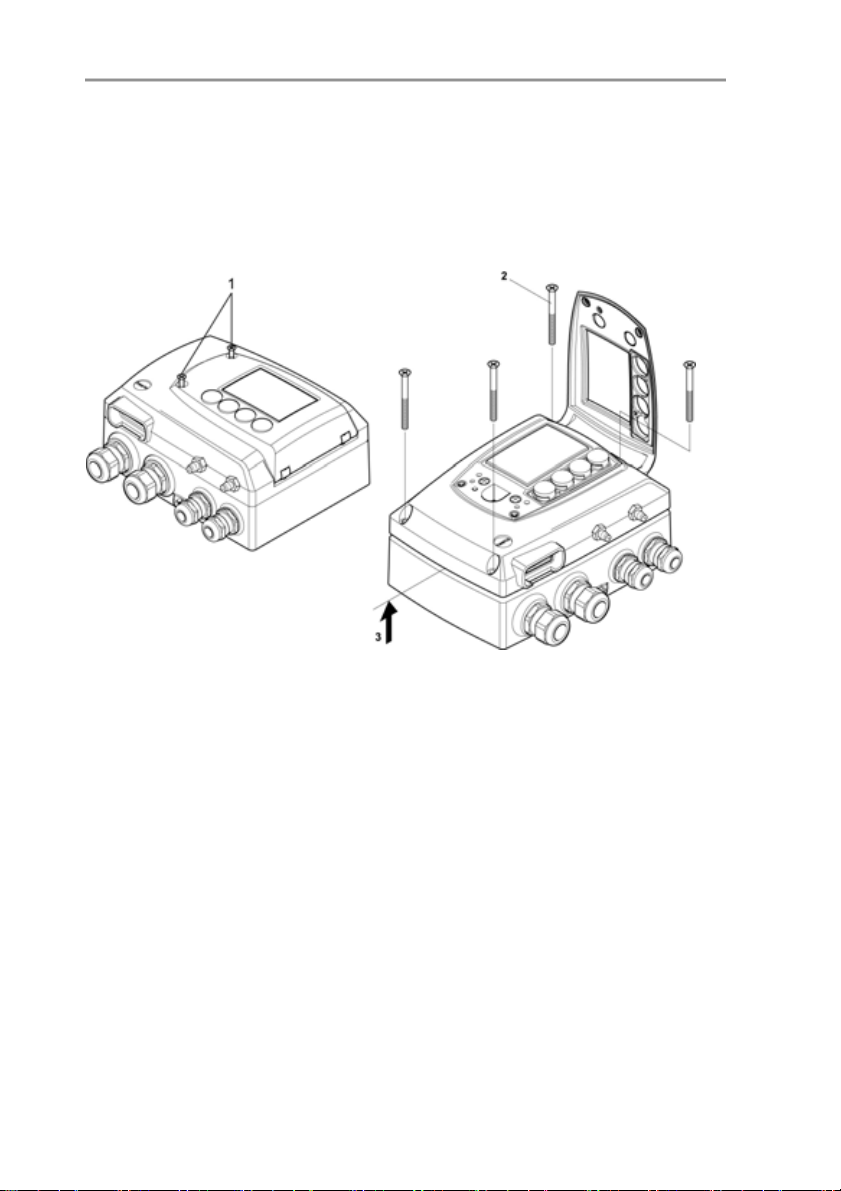
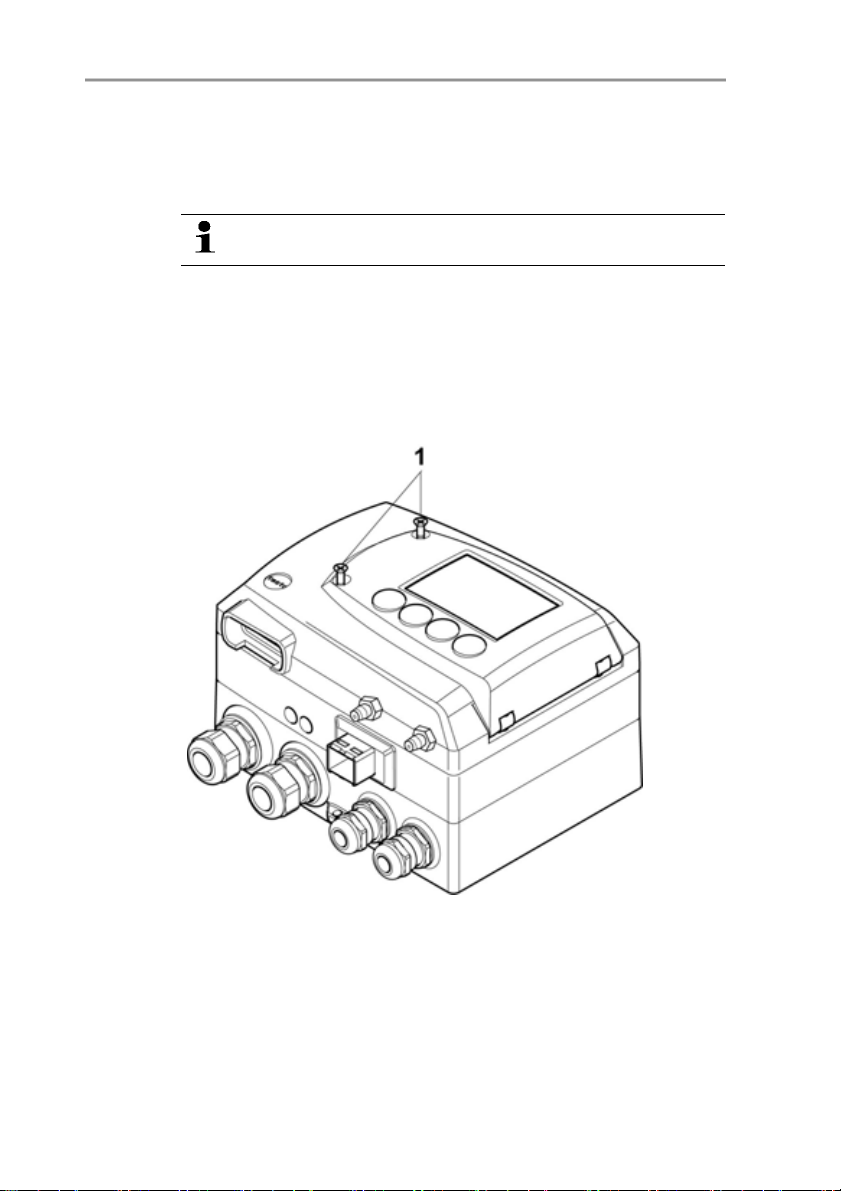
4.3.1. Inserting Ethernet module (order no. 0554 6656)
The Ethernet module can be ordered retroactively as an accessory.
It can easily be installed in the testo 6381 transmitter.
✓ The probe connector must be disconnected.
1. Loosen screw connection (1) of service flap and open the flap.
2. Loosen and remove housing screws (2).
3. Remove upper part of housing (3) and place on a clean surface.
23
4 Transmitter
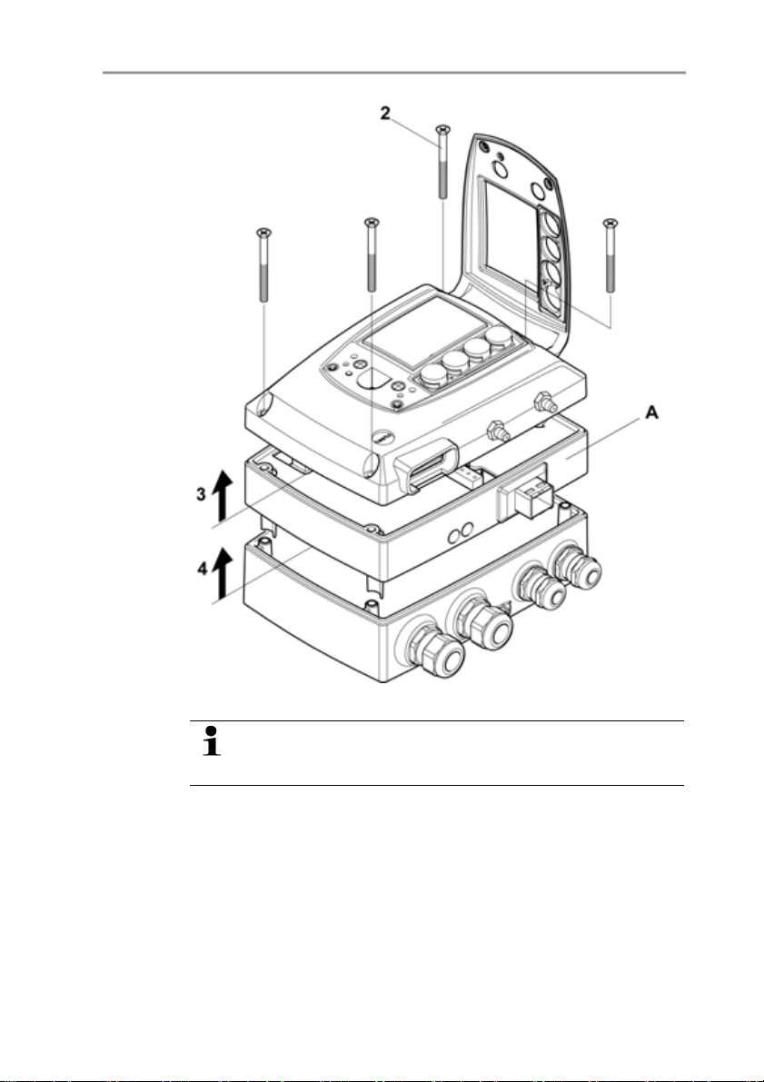
24
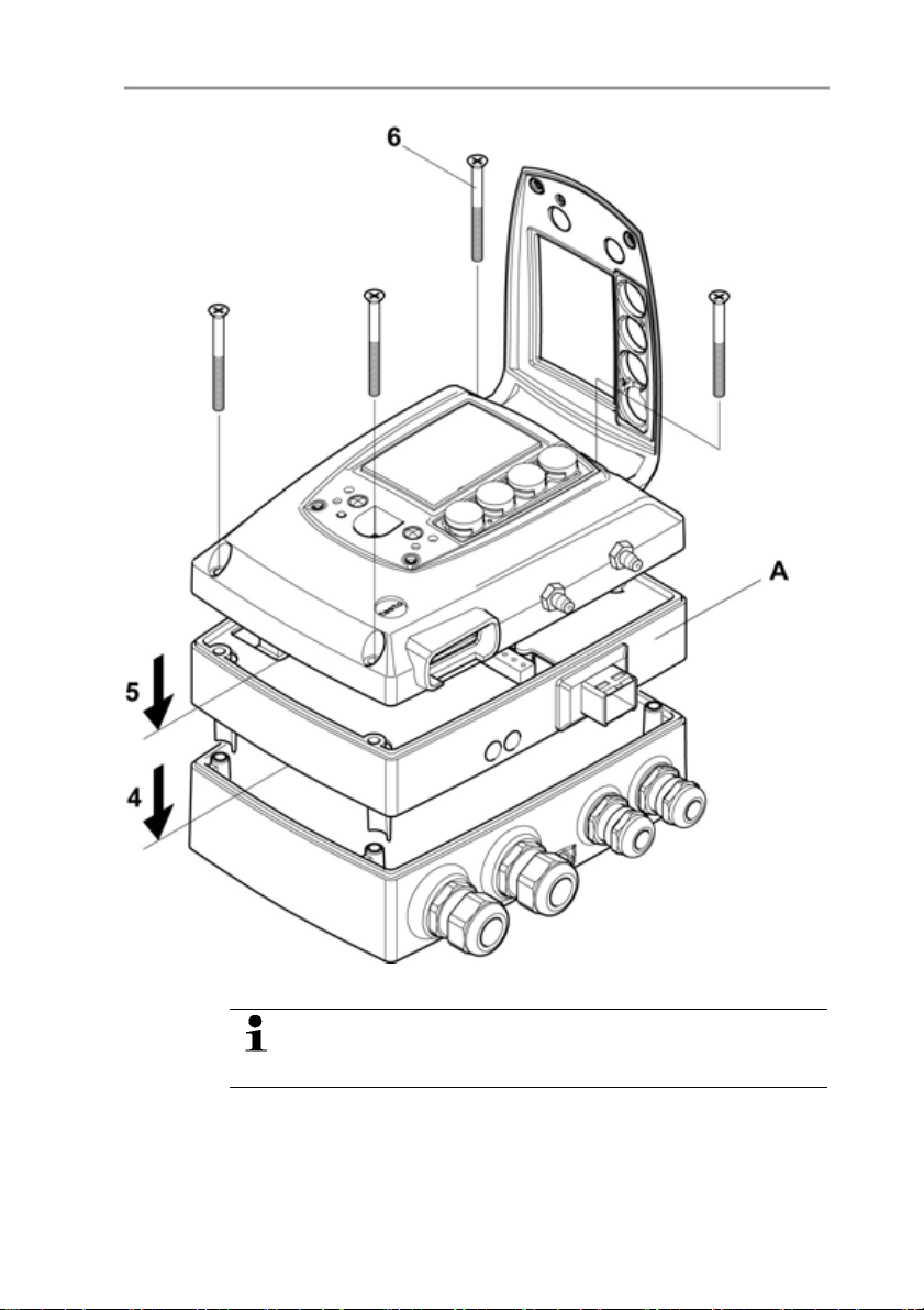
4. Place Ethernet module (A) on lower part of instrument (4).
First set the desired operating mode via the DIP switch (see
Setting the Ethernet module, page 36) before fixing the
instrument in place.
5. Set on upper part of instrument (5) and fix in place using the
housing screws (6) provided in the accessories.
4 Transmitter
Pos: 41 /TD/Erste Schritte/MUF 63xx/Wandmontage 638 x @ 3\mod_1234777599007_79. doc @ 25840 @ 3455
4.3.2. Assembling the instrument
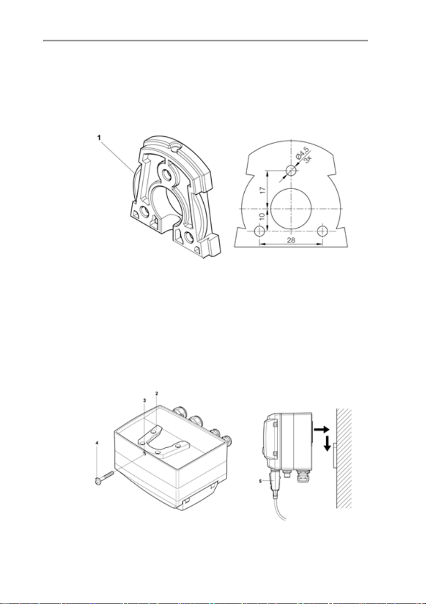
4.3.2.1. Wall mounting (for testo 6611, 6613, 6614, 6615, 6617 probes)
Attaching rear panel bracket
1. Remove locking screw (see item (4) of drawing below) and
detach rear panel bracket from plastic bracket (see item (2) of
drawing below).
2. Hold rear panel bracket in assembly position and mark the three
drill holes.
3. Drill three holes (Ø 5 mm) and insert dowels where necessary.
4. Screw on rear panel bracket.
Remember that the clamping brackets (1) must face the wall.
Fastening instrument to rear panel bracket
1. Slide plastic bracket (2) on the back of instrument onto rear
panel bracket until it engages (see arrows).
25
4 Transmitter
2. Insert screw (4) through hole (3) and screw into rear panel
bracket.
Pos: 42 /TD/Erste Schritte/MUF 63xx/Kanalmontage @ 3\m od_1234778800983_79.d oc @ 25859 @ 4
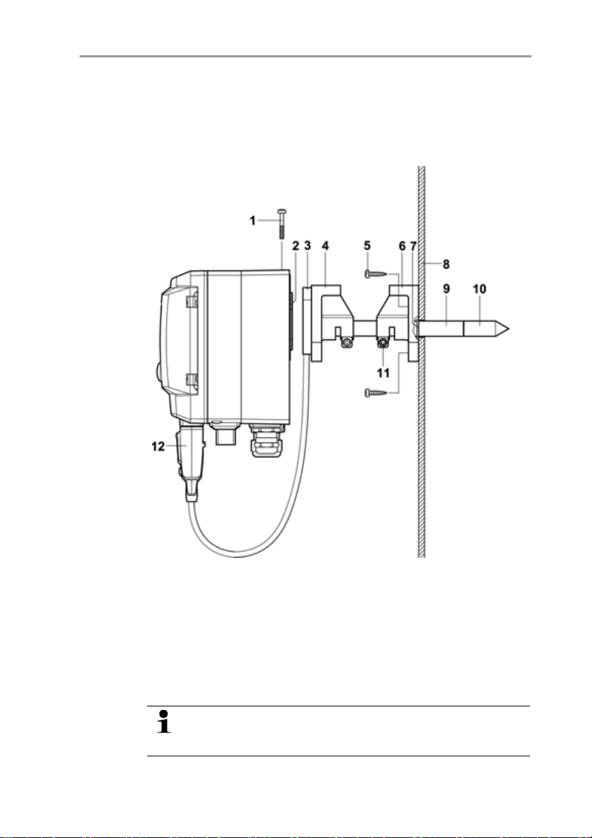
4.3.2.2. Duct mounting (for testo 6612 probes)
3. Insert probe connector (5) into socket until it engages.
26
1. Hold wall/duct bracket (order no. 0554 6651) (6) against duct
wall (8) and mark drill holes for wall/duct bracket and probe
shaft.
2. Drill a hole (Ø 12.5 mm) in the duct wall to feed through the
probe shaft.
3. Fasten wall/duct bracket (6) to duct wall with screws (5).
4. Push probe shaft (9) with filter (10) through the middle hole of
the mounting bracket.
The wall/duct bracket (6) has an O-ring (7) to seal it against
the duct. Feed the probe shaft (9) carefully through the
wall/duct bracket so that the O-ring is not damaged.
5. Fix the correct position of the probe shaft (9) with screw (11)
and mark (insert probe shaft as far as possible).
6. Slide plastic bracket (2) on the back of the transmitter onto
bracket (3, 4) until it engages.
Take the weight of the transmitter into account. Ensure that
the brackets (4, 6) are fastened securely.
7. Insert screw (1) through the hole on the top of the instrument
and screw into bracket (3).
Pos: 43 /TD/Erste Schritte/MUF 63xx/Gerät anschließ en Ethernet @ 3\mod_1234779 843987_79.doc @ 25897 @ 35
8. Insert probe connector (12) into socket until it engages.
4.3.3. Connecting the instrument
4 Transmitter
Opening the instrument
1. Loosen screw connection (1) of service flap and open the flap.
27
4 Transmitter
28
2. Loosen and remove housing screws (2).
The Ethernet module (A) is already detached from the
upper and lower parts of the housing by removing the
housing screws (2).
3. Remove upper part of housing (3) and place on a clean surface.
4. Remove Ethernet module (A) from lower part of housing (4) and
also place on a clean surface.
WARNING
Electrical voltage
Danger of injury!
> De-energize the mains connection before connecting the
transmitter.
Only have the transmitter wired and connected by
Pos: 44 /TD/Erste Schritte/MUF 63xx/Anschlussüber sicht 638x @ 3\mod_12347 80656658_79.doc @ 25935 @ 4
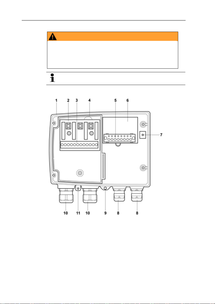
4.3.3.1. Overview of terminals
authorized personnel with the voltage disconnected.
4 Transmitter
1 Lower part of housing 7 Earthing terminal (internal)
2 Relay board (option) 8 M 16 x 1.5 screw connection*
3 Relay terminals 9 Earthing terminal (external)
4 Insulating trough for relay
10 M 20 x 1.5 screw connection*
board
5 Terminal strip for voltage
supply and analog outputs
6 Terminal board
11 Eyelet for measuring point
panel
* Alternatively, NPT cable
coupling or M plug-in connection
29
4 Transmitter
The following description of the terminals refer to this
Pos: 45 /TD/Erste Schritte/MUF 63xx/Spannungsver sorgung/Analogausgä nge anschließen 638x @ 3\ mod_1234784598344_79. doc @ 25954 @ 45
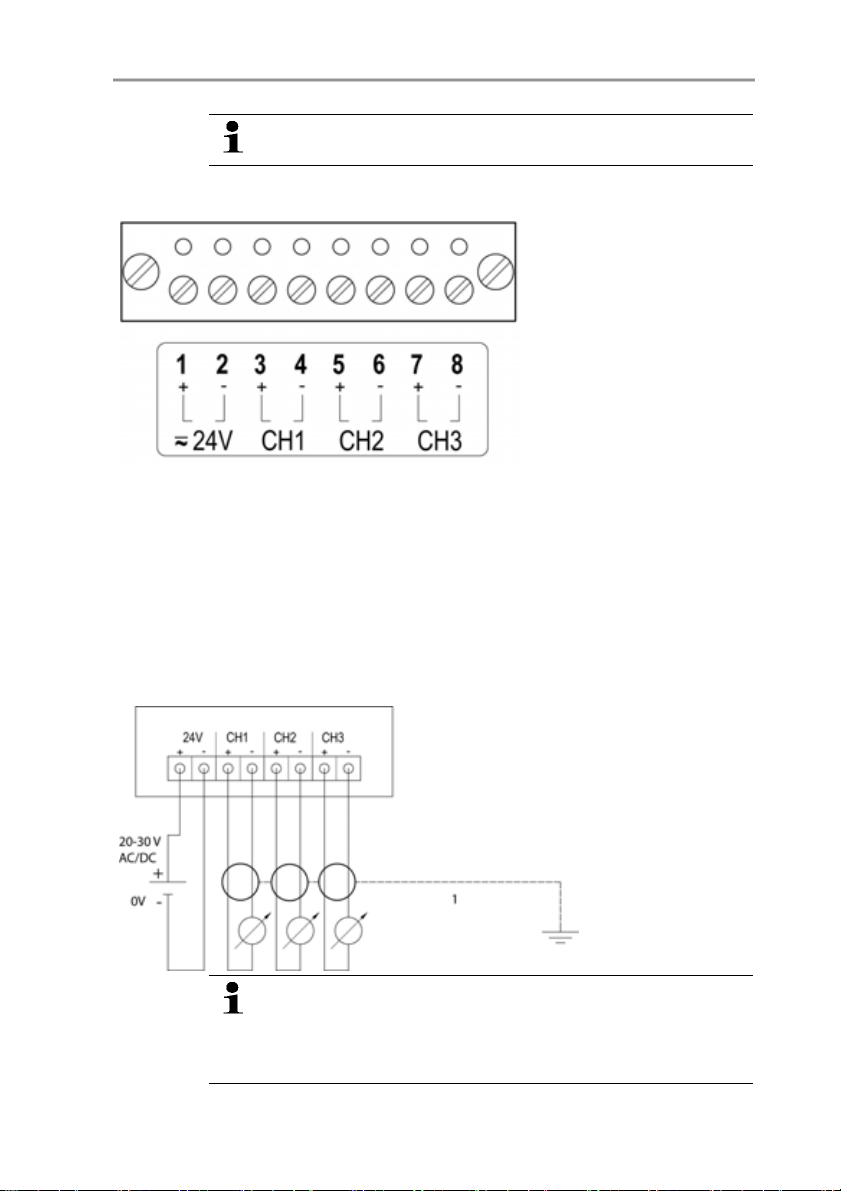
4.3.3.2. Connecting voltage supply and analog outputs
overview and its numbering.
Terminal strip for voltage
supply and analog outputs,
item (5) of overview of
terminals, page 29
1. Feed cable with voltage supply and analog signal lines through
opened M 16 x 1.5 screw connection (item (8) in the overview of
terminals, page 29).
2. Strip the cable ends, clamp wire end ferrules on and screw
down onto voltage terminals.
3. Close M 16 x 1.5 screw connection (item (8) in the overview of
terminals, page 29).
30
Wiring diagram for 4-wire system (0 to 20 mA/4 to 20 mA/0 to
1 V/0 to 5 V/0 to 10 V)
1 1 or 3 channels,
0 to 20 mA/4 to
20 mA max.
load per 500 Ω
0 to 1 V/0 to
5
V /
0 to 10 V
Requirement for the connecting cable of the supply:
• Insulated with cross-section of at least 0.25 mm².
• The supply line must be secured against exceeding
0.5 A.
 Loading...