

Page 1
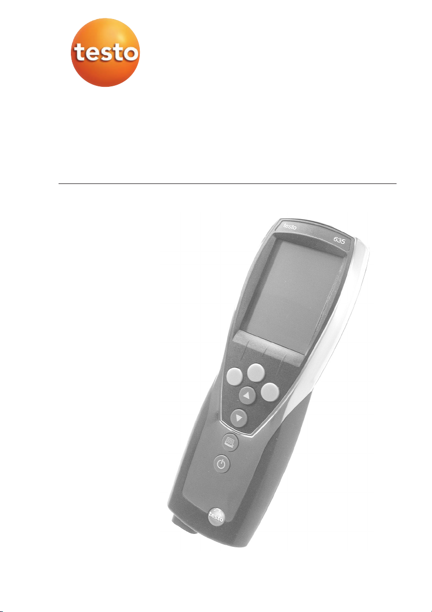
Feuchte-/Temperatur-/ Drucktaupunkt-Messgerät
testo 635
Bedienungsanleitung de
Instruction manual en
Inhalt
Allgemeine Hinweise ............................................2
1. Sicherheitshinweise..............................................4
2. Bestimmungsgemäße Verwendung......................5
3. Produktbeschreibung ..........................................6
3.1 Anzeige- und Bedienelemente ........................................6
3.2 Schnittstellen ..................................................................8
3.3 Spannungsversorgung ....................................................8
4. Inbetriebnahme ....................................................9
5. Bedienung..........................................................10
5.1 Fühler anschließen ........................................................10
5.2 Ein- / Ausschalten ........................................................10
5.3 Displaybeleuchtung ......................................................11
6. Gerät einstellen ..................................................12
6.1 Konfigurationsmenü ......................................................12
6.1.1 Profil................................................................................12
6.1.2 Einheiten ........................................................................13
6.1.3 Gerät ..............................................................................13
6.1.4 Fühler..............................................................................14
6.1.5 Sprache . .......................................................................16
6.2 Hauptmenü ..................................................................17
6.2.1 Speicher (nur 635-2 ) ......................................................18
6.2.2 Messreihe (nur 635-2 )....................................................19
6.2.3 Mittelwert ......................................................................20
6.2.4 Berechnung ....................................................................20
6.2.5 Material ..........................................................................22
6.2.6 Zyklisch Drucken (nur 635-1) ..........................................22
7. Messen ..............................................................23
8. Wartung und Pflege............................................26
9. Fragen und Antworten........................................27
10. Technische Daten ..............................................28
11. Zubehör / Ersatzteile ..........................................29
www.GlobalTestSupply.com
Page 2
Allgemeine Hinweise2
Allgemeine Hinweise
Dieses Kapitel gibt wichtige Hinweise zur Nutzung der vorliegenden
Dokumentation.
Diese Dokumentation enthält Informationen, die für einen sicheren und
effizienten Einsatz des Produkts beachtet werden müssen.
Lesen Sie diese Dokumentation aufmerksam durch und machen Sie sich mit
der Bedienung des Produkts vertraut, bevor Sie es einsetzen. Bewahren Sie
dieses Dokument griffbereit auf, um bei Bedarf nachschlagen zu können.
Kennzeichnungen
Darstellung Bedeutung Bemerkungen
Warnhinweis: Warnung! Warnhinweis aufmerksam lesen und die genannten
Vorsichtsmaßnahmen treffen! Schwere Körperverletzungen können
eintreten, wenn die genannten Vorsichtsmaßnahmen nicht getroffen
werden.
Warnhinweis: Vorsicht! Warnhinweis aufmerksam lesen und die genannten
Hinweis Gibt hilfreiche Tipps und Informationen.
±, 1, 2 Handlungsziel Nennt das Ziel, welches durch nachfolgend beschriebene Handlungs-
Voraussetzung Voraussetzung muss erfüllt sein, damit eine Handlung wie
i, 1, 2, ... (Handlungs-)Schritt Handlungsschritte ausführen. Bei nummerierten Handlungsschritten
Text Displaytext Text erscheint auf dem Gerätedisplay.
Taste
- Resultat Nennt das Ergebnis eines vorangegangenen (Handlungs-)Schritts.
º Querverweis Verweis auf weiterführende oder detailliertere Informationen.
Bedientaste Taste drücken.
Funktionstaste Taste drücken.
Vorsichtsmaßnahmen treffen! Leichte Körperverletzungen oder Sachschäden können eintreten, wenn die genannten Vorsichtsmaßnahmen
nicht getroffen werden.
schritte erreicht wird. Bei nummerierten Handlungszielen die
vorgegebene Reihenfolge beachten!
beschrieben ausgeführt werden kann.
die vorgegebene Reihenfolge beachten!
www.GlobalTestSupply.com
Page 3
Allgemeine Hinweise 3
Kurzschreibweise
In diesem Dokument wird eine Kurzschreibweise verwendet, um Handlungsschritte (z. B. den Aufruf einer Funktion) darzustellen.
Beispiel: Funktion „Gerätedaten“ aufrufen
Kurzschreibweise: Gerät ¬¬Ger.-Dat. ¬ .
1) (2) (3) (4)
(
OKOK
Erforderliche Handlungsschritte:
1 Mit / die Funktion Gerät wählen.
2 Mit Auswahl bestätigen.
3 Mit / die Funktion Ger.-Dat. wählen.
4 Mit Auswahl bestätigen.
OK
OK
deenfresitptsvnl????
www.GlobalTestSupply.com
Page 4

1. Sicherheitshinweise4
1. Sicherheitshinweise
Dieses Kapitel nennt allgemeine Regeln, die für einen sicheren Umgang mit
dem Produkt unbedingt beachtet werden müssen.
Personenschäden/Sachschäden vermeiden
i Mit dem Messgerät und Fühlern nicht an oder in der Nähe von spannungs-
führenden Teilen messen.
i Das Messgerät/Messzellen nie zusammen mit Lösungsmitteln lagern, keine
Trockenmittel verwenden.
Produktsicherheit/Gewährleistungsansprüche wahren
i Das Messgerät nur innerhalb der in den Technischen Daten vorgegebenen
Parameter betreiben.
i Das Messgerät nur sach- und bestimmungsgemäß verwenden. Keine
Gewalt anwenden.
i Handgriffe und Zuleitungen nicht Temperaturen über 70°C aussetzen, wenn
diese nicht ausdrücklich für höhere Temperaturen zugelassen sind. Temperaturangaben auf Sonden/Fühlern beziehen sich nur auf den Messbereich der
Sensorik.
i Das Messgerät nur öffnen, wenn dies zu Wartungs- oder Instandhaltungs-
zwecken ausdrücklich in der Dokumentation beschrieben ist.
Nur Wartungs- und Instandsetzungsarbeiten durchführen, die in der Dokumentation beschrieben sind. Dabei die vorgegebenen Handlungsschritte
einhalten. Aus Sicherheitsgründen nur Original-Ersatzteile von Testo verwenden.
Fachgerecht entsorgen
i Defekte Akkus/leere Batterien an den dafür vorgesehenen Sammelstellen
abgeben.
i Produkt nach Ende der Nutzungszeit an Testo senden. Wir sorgen für eine
umweltschonende Entsorgung.
www.GlobalTestSupply.com
Page 5

2. Bestimmungsgemäße Verwendung 5
2. Bestimmungsgemäße
Verwendung
Dieses Kapitel nennt die Anwendungsbereiche, für die das Produkt bestimmt
ist.
Setzen Sie dass Produkt nur für die Bereiche ein, für die es konzipiert wurde.
Im Zweifelsfall bitte bei Testo nachfragen.
Das testo 635 ist ein kompaktes Messgerät zur Messung von Temperatur,
Feuchte und Drucktaupunkt.
Das Produkt wurde für folgende Aufgaben/Bereiche konzipiert:
· Raumklimamessung
· Einregeln und Prüfen von raumluft-technischen Anlagen
· Messung des Drucktaupunkts in Druckluftsystemen
· Materialfeuchtebetrachtung
In folgenden Bereichen darf das Produkt
· In explosionsgefährdeten Bereichen.
· Zu diagnostischen Messungen im medizinischen Bereich
nicht
eingesetzt werden:
deenfresitptsvnl????
www.GlobalTestSupply.com
Page 6
3. Produktbeschreibung6
3. Produktbeschreibung
Dieses Kapitel gibt eine Übersicht über die Komponenten des Produkts und
deren Funktionen.
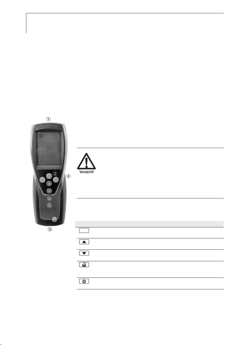
3.1 Anzeige- und Bedienelemente
Übersicht
Infrarot-, USB-Schnittstelle
Display (Beleuchtung zuschaltbar)
Bedientasten
Rückseite: Batterie- und Funkmodulfach, Haltemagnete
Starke Magnete
Beschädigung aanderer GGeräte!
i
Sicherheitsabstand zu Produkten einhalten,
die durch Magnetismus beschädigt werden
können (z. B. Monitore, Computer,
Herzschrittmacher, Kreditkarten).
Fühlerbuchse(n)
Tastenfunktionen
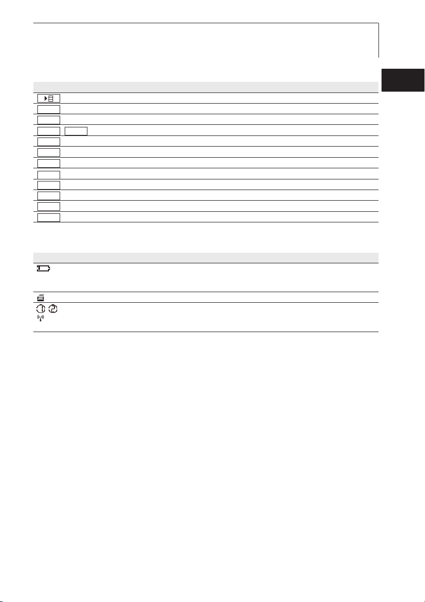
Taste Funktionen
Funktionstaste (3x): Funktion ist abhängig von der aktuellen Tastenbelegung
Anzeige der 1. Messwertzeile wechseln
Im Konfigurationsmodus: Wert erhöhen, Option wählen
Anzeige der 2. Messwertzeile wechseln
Im Konfigurationsmodus: Wert verringern, Option wählen
Daten drucken
Nur 635-1: Ist die Funktion Zyklisches Drucken aktiviert, wird die
programmierte Messreihe gestartet
Gerät einschalten, Displaybeleuchtung ein-/ ausschalten;
Gerät ausschalten (gedrückt halten)
www.GlobalTestSupply.com
Page 7
3. Produktbeschreibung 7
Funktionstasten (Belegung abhängig von Profil und Einstellung)
Taste Funktionen
(Haupt-)Menü öffnen
OK
ESC
ACTHold
/ Messwert halten/ Aktuellen Messwert anzeigen
Reset
Mittl
Messr
Start
Ende
M+
Mat
Funk
Eingabe bestätigen
Abbrechen
Max.-/Min-Werte auf aktuellen Messwert zurücksetzen
Menüpunkt „Zeitliche Mittelwertbildung“ öffnen
Menüpunkt „Messreihe“ öffnen (nur 635-2)
Messreihe starten (nur 635-2)
Messreihe beenden (nur 635-2), Zyklisches Drucken beenden (nur 635-1)
Werte speichern (nur 635-2)
Menüpunkt „Material“ öffnen
Menüpunkt „Funk“ öffnen
Wichtige Displayanzeigen
Anzeige Bedeutung
Batteriekapazität (nur bei Akku-/ Batteriebetrieb):
· Im Batteriesymbol leuchten 4 Segmente: Batterie des Geräts ist voll
· Im Batteriesymbol leuchten keine Segmente: Batterie des Geräts ist fast leer
(blinkt) Druckfunktion: Daten werden an den Drucker gesendet
, Messkanal-Nr.: Kanal 1, Kanal 2.
Handelt es sich bei einem Messkanal um einen Funk-Kanal, leuchtet zusätzlich zur Messkanal-Nr.
das Funk-Symbol.
deenfresitptsvnl????
www.GlobalTestSupply.com
Page 8

3. Produktbeschreibung8
3.2 Schnittstellen
Infrarot-Schnittstelle
Über die Infrarot-Schnittstelle an der Kopfseite des Geräts können Messdaten
an einen Testo-Protokolldrucker gesendet werden.
USB-Schnittstelle
Über die USB-Schnittstelle an der Kopfseite des Geräts kann das Netzteil
(Zubehör) zur Spannungsversorgung des Geräts angeschlossen werden.
Geräte mit Speicher: Mess-/Gerätedaten können über die USB-Schnittstelle
mit einem PC ausgetauscht werden. Das Messgerät ist ein HighPower-Gerät,
evtl. ist ein zusätzlicher USB-Hub erforderlich!
Fühlerbuchse(n)
Über die Fühlerbuchse(n) an der Fußseite des Geräts können steckbare Messfühler angeschlossen werden.
Funkmodul (Zubehör)
Funkfühler dürfen nur in Ländern verwendet werden, in denen sie zugelassen
wurden (siehe Anwendungshinweise zum Funkfühler).
Über das Funkmodul können bis zu drei Funkfühler angeschlossen werden.
3.3 Spannungsversorgung
Die Spannungsversorgung erfolgt über drei Mignon-Batterien (im Lieferumfang)
bzw. -akkus bzw. über ein Netzteil (Zubehör). Das Laden von Akkus im Gerät
ist nicht möglich.
Legen Sie auch bei Betrieb über das Netzteil Batterien in das Gerät ein,
um ein Ausschalten des Geräts bei Stromunterbrechung zu verhindern.
www.GlobalTestSupply.com
Page 9

4. Inbetriebnahme 9
4. Inbetriebnahme
Dieses Kapitel beschreibt die Handlungsschritte, die zur Inbetriebnahme des
Produkts erforderlich sind.
Batterien/Akkus uund FFunkmodul ((Zubehör) eeinlegen:
²
1 Die beiden Schrauben auf der Rückseite des Geräts lösen und
Batteriefachdeckel abnehmen.
2 Batterien/Akkus (3x Mignon) in das Batteriefach einlegen. Polung
beachten!
3 Funkmodul (Zubehör) in den Funkmodulschacht einschieben, bis dieses
einrastet. Führungsnut beachten.
4 Batteriefachdeckel aufsetzen, andrücken und durch Anziehen der beiden
Schrauben befestigen.
deenfresitptsvnl????
www.GlobalTestSupply.com
Page 10

5. Bedienung10
5. Bedienung
Dieses Kapitel beschreibt die Handlungsschritte, die beim Einsatz des Produkts
häufig ausgeführt werden.
5.1 Fühler anschließen
Steckbare Fühler
Steckbare Fühler müssen vor dem Einschalten des Messgeräts angeschlossen
werden, damit diese vom Messgerät erkannt werden.
i Anschlussstecker des Fühlers in die Fühlerbuchse des Messgeräts
stecken.
Funkfühler
Funkfühler dürfen nur in Ländern verwendet werden, in denen sie zugelassen
wurden (siehe Anwendungshinweise zum Funkfühler).
Zur Verwendung von Funkfühlern ist ein Funkmodul erforderlich (Zubehör). Das
Funkmodul muss vor dem Einschalten des Messgeräts angeschlossen werden,
damit dieses vom Messgerät erkannt wird.
Jeder Funkfühler besitzt eine Fühler-ID (Identifikationsnummer), diese muss im
Konfigurationsmodus eingestellt werden.
º Siehe Kapitel FÜHLER, S. 14.
5.2 Ein-/Ausschalten
Gerät eeinschalten:
²
i drücken.
- Die Messansicht wird geöffnet: Der aktuelle Messwert wird angzeigt
bzw. ---- leuchtet, wenn kein Messwert verfügbar ist.
Geräte mit Speicher: Der aktivierte Messort wird angezeigt (oberste
Zeile).
-ooder-
Gerät wird zum ersten Mal eingeschaltet, ein Reset wurde durchgeführt
oder die Spannungsversorgung war für längere Zeit unterbrochen:
- Funktion Language wird geöffnet.
º Siehe Kapitel
LANGUAGE, S. 16.
www.GlobalTestSupply.com
Page 11
Gerät aausschalten:
²
i gedrückt halten (ca. 2s), bis das Display erlischt.
5.3 Displaybeleuchtung
Displaybeleuchtung eein-//ausschalten:
²
Das Gerät ist eingeschaltet.
i drücken.
5. Bedienung 11
deenfresitptsvnl????
www.GlobalTestSupply.com
Page 12
6. Gerät einstellen12
6. Gerät einstellen
Dieses Kapitel beschreibt die Handlungsschritte, die zur Anpassung des Messgeräts an spezielle Messaufgaben erforderlich sind.
6.1 Konfigurationsmenü
Im Konfigurationsmenü werden die Grundeinstellungen des Messgeräts vorgenommen.
Konfigurationsmenü ööffnen:
²
Das Gerät befindet sich in der Messansicht.
i gedrückt halten (ca. 2s) bis Konfig. angezeigt wird.
ESC
Mit gelangen Sie jeweils eine Menüebene zurück. Zum Verlassen
des Konfigurationsmenüs mehrfach drücken, bis das Gerät zur
Messansicht gewechselt hat.
6.1.1 Profil
ESC
Das Gerät besitzt vordefinierte Messprofile, die auf spezielle Anwendungsgebiete zugeschnitten sind.
Die Profileinstellung beeinflußt folgende Punkte im Messmodus:
· Belegung der Funktionstasten
· Anzahl der verfügbaren Funktionen
· Struktur des Hauptmenüs
Im Standardprofil sind alle Funktionen verfügbar. In den anwendungsspezifischen Messprofilen sind die verfügbaren Funktionen bedarfsgerecht reduziert,
um einen schnelleren Zugriff zu gewährleisten.
Profil eeinstellen:
²
Das Konfigurationsmenü ist geöffnet, Konfig. wird angezeigt.
1 Profil ¬ .
2 Mit / gewünschtes Profil wählen und mit bestätigen.
OK
OK
www.GlobalTestSupply.com
Page 13
6. Gerät einstellen 13
6.1.2 Einheiten
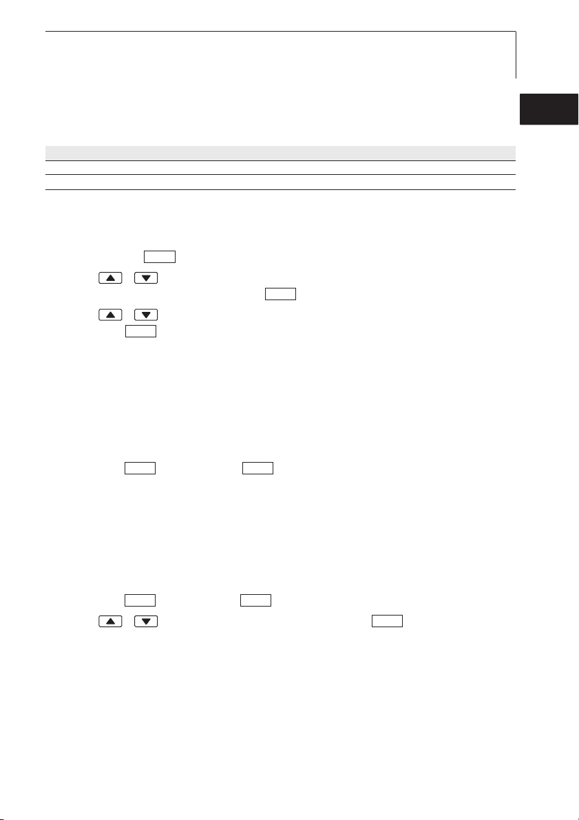
Vordefinierte Systeme und individuelle Einstellmöglichkeiten:
Messgröße System ISO System US Individuelle Einstellmöglichkeiten
Temperatur °C °F °C, °F
Druck hPa inchH2O mbar, Pa, hPa, kPa, inchH2O
Einheiten eeinstellen:
²
Das Konfigurationsmenü ist geöffnet, Konfig. wird angezeigt.
1 Einheiten ¬ .
2 Mit / ISO/US (System-Einstellung) oder eine Messgröße (individu-
elle Einstellung) wählen und mit bestätigen.
3 Mit / das Einheitensystem bzw. die gewünschte Einheit einstellen
und mit bestätigen.
OK
OK
OK
6.1.3 Gerät
Gerätedaten
Gerätedaten aanzeigen:
²
Das Konfigurationsmenü ist geöffnet, Konfig. wird angezeigt.
1 Gerät ¬¬Ger.-Dat. ¬ .
- Die Firmware-Version und die Seriennummer des Geräts werden
angezeigt.
OKOK
deenfresitptsvnl????
Datum/Uhrzeit
Datum/Uhrzeit eeinstellen:
²
Das Konfigurationsmenü ist geöffnet, Konfig. wird angezeigt.
1 Gerät ¬¬Dat./Zeit ¬ .
2 Mit / den Wert für Jahr einstellen und mit bestätigen.
3 Die weiteren Werte wie in Handlungsschritt 2 beschrieben einstellen.
www.GlobalTestSupply.com
OKOK
OK
Page 14
6. Gerät einstellen14
Batterietyp
Um eine korrekte Anzeige der Batteriekapazität zu gewährleisten, muss der verwendete Batterietyp eingestellt werden.
Batterietyp eeinstellen:
²
Das Konfigurationsmenü ist geöffnet, Konfig. wird angezeigt.
1 Gerät ¬¬Bat-Typ ¬ .
2 Mit / Batterie oder Akku wählen und mit bestätigen.
OKOK
OK
Auto OFF
Ist Auto OFF eingeschaltet, schaltet sich das Gerät nach 10min ohne Tastenbetätigung automatisch aus. Ausnahme: Zyklisches Drucken (Geräte ohne
Speicher) bzw. ein Messprogramm (Geräte mit Speicher) ist aktiv.
Auto OOFF eein-//auschalten:
²
Das Konfigurationsmenü ist geöffnet, Konfig. wird angezeigt.
1 Gerät ¬¬Auto OFF ¬ .
2 Mit / Ein oder Aus wählen und mit bestätigen.
OKOK
OK
Reset
Beim Durchführen eines Resets wird das Gerät auf die Werkseinstellungen
zurückgesetzt, alle Einstellungen/Daten werden gelöscht. Ausnahme: Sprache,
Datum/Uhrzeit.
Reset ddurchführen:
²
Das Konfigurationsmenü ist geöffnet, Konfig. wird angezeigt.
1 Gerät ¬¬Reset ¬ .
2 Mit Reset durchführen oder mit abbrechen.
OKOK
ESCOK
Max.-/Min.-Druckfunktion einstellen
Ist pr MinMaxAuto eingeschaltet, werden Minimal- und Maximalwerte beim
Drucken der Messwerte mit ausgedruckt.
pr MinMax eein-//auschalten:
²
Das Konfigurationsmenü ist geöffnet, Konfig. wird angezeigt.
1 Gerät ¬¬pr MinMax ¬ .
2 Mit / Ein oder Aus wählen und mit bestätigen.
www.GlobalTestSupply.com
OKOK
OK
Page 15
6. Gerät einstellen 15
6.1.4 Fühler
Funk
Funkfühler dürfen nur in Ländern verwendet werden, in denen sie zugelassen
wurden (siehe Anwendungshinweise zum Funkfühler).
Zur Verwendung von Funkfühlern ist ein Funkmodul erforderlich (Zubehör). Das
Gerät kann mit maximal drei Funkfühlern eine Verbindung herstellen.
Jeder Funkfühler besitzt eine Fühler-ID (RF-ID). Diese besteht aus den letzten
3 Ziffern der Serien-Nr. und der Position des Schiebeschalters (H oder L) im
Funkfühler.
Funkfühler eeinrichten:
²
Ein Funkmodul (Zubehör) ist in das Gerät eingelegt.
º Siehe Kapitel INBETRIEBNAHME, S. 9.
Das Konfigurationsmenü ist geöffnet, Konfig. wird angezeigt.
Der Funkfühler ist eingeschaltet und die Übertragungsrate ist auf 2 Mess-
werte pro Sekunde eingestellt (siehe Anwendungshinweise zum Funk-
fühler).
1 Fühler ¬¬Funk ¬ .
2 Mit / die gewünschte Kanal-Nr. für den Funkfühler wählen (F. 1 , F. 2
oder F. 3 ) und mit bestätigen.
OK
- Das Gerät sucht nach eingeschalteten Funkfühlern im Empfangsbereich.
- Die Fühler-ID der gefundenen Funkfühler wird angezeigt.
OKOK
deenfresitptsvnl????
Wurden keine Funkfühler gefunden, kann dies folgende Ursachen haben:
· Der Funkfühler ist nicht eingeschaltet oder die Batterie des Funkfühlers
ist leer.
· Der Funkfühler befindet sich außerhalb der Reichweite des Messgeräts.
· Störquellen beeinflussen die Funkübertragung (z. B. Stahlbeton,
Metallgegenstände, Wände oder andere Barrieren zwischen Empfänger
und Sender, andere Sender gleicher Frequenz, starke
elektromagnetische Felder).
i Falls erforderlich: Mögliche Ursachen für die Störung der Funküber-
tragung beseitigen.
Alternativ ist auch eine manuelle Eingabe der Fühler-ID möglich.
MAN
i ¬ Mit / die Fühler-ID eingeben.
www.GlobalTestSupply.com
Page 16
6. Gerät einstellen16
3
Mit / den Fühler wählen, der der gewählten Kanal-Nr. zugeordnet
werden soll.
4 Angezeigter Funkfühler mit der gewählten Kanal-Nr. zuordnen oder
Funktion mit verlassen, ohne die Fühlerkonfiguration zu ändern.
ESC
OK
Abgleich Feuchtefühler
Die Funktion ist nur verfügbar, wenn ein Feuchtefühler gesteckt ist.
Die Abgleichwerte können auf die Werkseinstellungen zurückgesetzt werden
(Reset). Ein 2-Punkt-Abgleich kann durchgeführt werden.
Reset dder AAbgleichwerte ddurchführen:
²
Das Konfigurationsmenü ist geöffnet, Konfig. wird angezeigt.
1 Fühler ¬¬Abgleich ¬ .
2 Mit / Reset wählen und mit 2x bestätigen.
OKOK
OK
- Die Abgleichwerte werden auf die Werkseinstellungen zurückgesetzt.
Abgleich ddurchführen:
²
Das Konfigurationsmenü ist geöffnet, Konfig. wird angezeigt.
1 Fühler ¬¬Abgleich ¬ .
2 Mit / Abgleichpunkt P1 oder P2 wählen und mit 2x
OKOK
OK
bestätigen.
3 Feuchtefühler in das Referenzmedium geben und Angleichzeit abwarten.
- Der aktuelle Feuchte-Messwert und der Abgleichpunkt (Sollwert) wird
angezeigt.
4 Mit das Abgleichmenü starten.
5 Mit Abgleich speichern oder mit abbrechen.
OK
ESCOK
Te-Typ
Die im Gerät hinterlegte Fühlerkennlinie kann auf den verwendeten Fühlertyp
eingestellt werden.
Fühlertyp eeinstellen:
²
Das Konfigurationsmenü ist geöffnet, Konfig. wird angezeigt.
1 Fühler ¬¬Te-Typ ¬ .
2 Mit / den gewünschten Fühlertyp wählen und mit
OKOK
OK
bestätigen.
www.GlobalTestSupply.com
Page 17
6. Gerät einstellen 17
6.1.5 Language
Sprache eeinstellen:
²
Das Konfigurationsmenü ist geöffnet, Konfig. wird angezeigt.
1 Language ¬ .
2 Mit / die gewünschte Sprache wählen und mit bestätigen.
OK
OK
6.2 Hauptmenü
Im Hauptmenü werden Einstellungen vorgenommen, mit denen das Messgerät
an die jeweile Messaufgabe angepaßt werden kann.
Das Gerät besitzt vordefinierte Messprofile, die auf spezielle Anwendungsgebiete zugeschnitten sind.
º Siehe Kapitel PROFIL, S. 12.
Die Profileinstellung beeinflußt die Anzahl der verfügbaren Funktionen und die
Struktur des Hauptmenüs.
Der in diesem Kapitel beschriebene Weg zum Aufruf der Funktionen im
Hauptmenü bezieht sind auf die Profil-Einstellung Standard. Ist ein anderes
Profil eingestellt, so kann sich der Weg zum Aufruf einzelner Funktionen
ändern bzw. die Funktion ist im eingestellten Profil nicht verfügbar. Einige
Funktionen sind nur verfügbar, wenn ein Fühler gesteckt ist bzw. ein Funkfühler eingeschaltet und angemeldet ist.
deenfresitptsvnl????
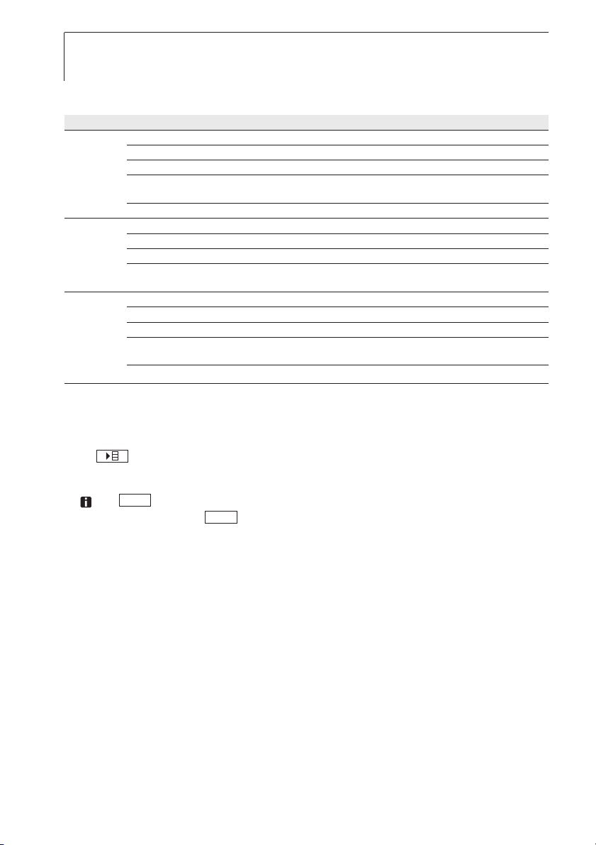
Menüübersicht testo 635-1
Profil Menüpunkte Funktion
Standard Berechnung Berechnung Wassergehalt, Taupunkt, Psychrometrische Temperatur,
Material Materialkennlinie aktivieren
Zykl. Drucken Zyklisches Drucken de-/aktivieren
Material Mittel Zeitliche/punktuelle Mittelwertbildung durchführen
Berechnung Berechnung Wassergehalt, Taupunkt, Psychrometrische Temperatur,
Zykl. Drucken Zyklisches Drucken de-/aktivieren
Funk Berechnung Berechnung Wassergehalt, Taupunkt, Psychrometrische Temperatur,
Material Materialkennlinie aktivieren
Zykl. Drucken Zyklisches Drucken de-/aktivieren
www.GlobalTestSupply.com
Differenztemperatur de-/aktivieren, Parameter „Alpha“ einstellen
Differenztemperatur de-/aktivieren, Parameter „Alpha“ einstellen
Differenztemperatur de-/aktivieren, Parameter „Alpha“ einstellen
Page 18
6. Gerät einstellen18
Menüübersicht testo 635-2
Profil Menüpunkte Funktion
Standard Speicher Messort aktivieren/anlegen, Protokolle drucken, Speicher löschen
Messreihe Messprogramm einstellen/de-/aktivieren
Mittel Zeitliche /punktuelle Mittelwertbildung durchführen
Berechnung Berechnung Wassergehalt, Taupunkt, Psychrometrische Temperatur,
Material Materialkennlinie aktivieren
Material Speicher Messort aktivieren/ anlegen, Protokolle drucken, Speicher löschen
Messreihe Messprogramm einstellen/de-/aktivieren
Mittel Zeitliche /punktuelle Mittelwertbildung durchführen
Berechnung Berechnung Wassergehalt, Taupunkt, Psychrometrische Temperatur,
Funk Speicher Messort aktivieren/ anlegen, Protokolle drucken, Speicher löschen
Messreihe Messprogramm einstellen/de-/aktivieren
Mittel Zeitliche /punktuelle Mittelwertbildung durchführen
Berechnung Berechnung Wassergehalt, Taupunkt, Psychrometrische Temperatur,
Material Materialkennlinie aktivieren
Hauptmenü ööffnen:
²
Differenztemperatur de-/aktivieren, Parameter „Alpha“ einstellen
Differenztemperatur de-/aktivieren, Parameter „Alpha“ einstellen
Differenztemperatur de-/aktivieren, Parameter „Alpha“ einstellen
Gerät befindet sich in der Messansicht.
i drücken.
- Menü wird angezeigt.
ESC
Mit gelangen Sie jeweils eine Menüebene zurück. Zum Verlassen
des Hauptmenüs mehrfach drücken, bis das Gerät zur Messansicht
ESC
gewechselt hat.
6.2.1 Speicher (nur 635-2)
Info
Der freie Speicherplatz wird angezeigt.
Messort
Der aktive Messort kann geändert werden. Es können max. 99 Messorte
angelegt werden. Die nummerischen Messortbezeichnungen (01 - 99) können
über die PC-Software in beliebige Texte (max. 10 Zeichen) geändert werden.
www.GlobalTestSupply.com
Page 19
6. Gerät einstellen 19
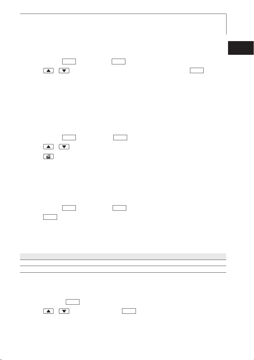
Aktiven MMessort äändern:
²
Das Hauptmenü ist geöffnet, Menü wird angezeigt.
1 Speicher ¬¬Messort ¬ .
2 Mit / den zu aktivierenden Messort wählen und mit
OKOK
OK
bestätigen.
Protokoll
Gespeicherte Messprotokolle können über die Infrarotschnittstelle auf einem
Testo-Protokolldrucker (Zubehör) ausgedruckt werden.
Messprotokoll ddrucken:
²
Das Hauptmenü ist geöffnet, Menü wird angezeigt.
1 Speicher ¬¬Protokoll ¬ .
2 Mit / das zu druckende Messprotokoll wählen.
3 Mit den Ausdruck des Messprotokolls starten.
OKOK
Löschen
Der gesamte Speicher mit allen Messprotokollen kann gelöscht werden.
Speicher llöschen:
²
Das Hauptmenü ist geöffnet, Menü wird angezeigt.
1 Speicher ¬¬Löschen ¬ .
2 Mit den gesamten Speicher löschen.
OK
OKOK
deenfresitptsvnl????
6.2.2 Messreihe (nur 635-2)
Eine Messreihe kann programmiert und de-/aktiviert werden:
Bezeichnung Beschreibung
Aus Messreihe ausgeschaltet: Messwerte können manuell gespeichert werden
AUTO Automatische Messreihe: Messtakt (mind. 1s) und Anzahl Messwerte frei einstellbar.
Messreihe ddeaktivieren:
²
Das Hauptmenü ist geöffnet, Menü wird angezeigt.
1 Messreihe ¬ .
2 Mit / Aus wählen und mit bestätigen.
- Das Gerät wechselt zur Messansicht.
OK
OK
www.GlobalTestSupply.com
Page 20
6. Gerät einstellen20
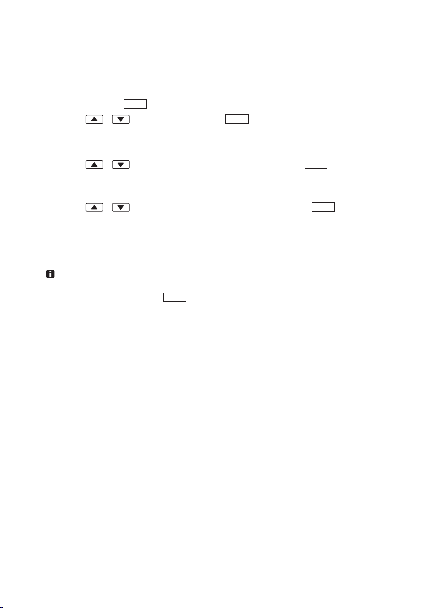
Messreihe AAUTO pprogrammieren uund aaktivieren:
²
Das Hauptmenü ist geöffnet, Menü wird angezeigt.
1 Messprog. ¬ .
2 Mit / AUTO wählen und mit bestätigen.
OK
OK
Der Messtakt wird in der Reihenfolge Stunden /Minuten/Sekundeneingestellt.
3 Mit / Messtakt in Stunden einstellen und mit bestätigen.
4 Einstellung für Minuten und Sekundenwie in Handlungsschritt 3 beschrie-
OK
ben vornehmen.
5 Mit / Anzahl der Messwerte einstellen und mit bestätigen.
OK
- Das Gerät wechselt zur Messansicht.
6.2.3 Mittelwert
Der Menüpunkt Mittelwertbildung ist nur im Gerät testo 635-2 verfügbar.
Beim Gerät testo 635-1 erfolgt der Aufruf der Funktion Mittelwertbildung
über die Funktionstaste .
Zur Durchführung einer Mittelwertbildung siehe Kapitel Messen, Seite 23.
Mittl
6.2.4 Berechnung
Bei eingeschalteter Berechung können aus den Messwerten
weitere Größen mit berechneten Werten angezeigt werden. Diese werden als
zusätzliche Messkanäle in der Messansicht angezeigt.
Zur Durchführung der Berechnung müssen bestimmte Messkanäle verfügbar
sein.
Folgende Größen können berechnet werden:
· Wassergehalt (in Gewichtsprozent zur Trockenmasse des Materials)
· Taupunkt (unterhalb 0°Ctd/32°Ftd werden Frost-/ -Reif-Punkttemperaturen
angezeigt)
· Psychrometrische Temperatur
Der zur Berechnung des U-Werts erforderliche Wärmeübergangskoeffizient
(Alpha) kann eingestellt werden.
Ebenso besteht die Möglichkeit, die Differenz aus zwei Messkanälen zu berechnen (Delta). Dies ist nur möglich, wenn die gewählten Messkanäle die gleiche
Einheit besitzen.
www.GlobalTestSupply.com
eines
Fühlers
Page 21
6. Gerät einstellen 21
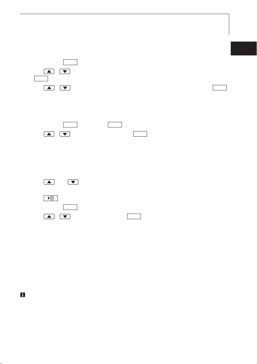
Messwert-BBerechnung dde-// aktivieren:
²
Das Hauptmenü ist geöffnet, Menü wird angezeigt.
1 Berechn. ¬ .
2 Mit / Messgröße wählen, die de-/aktiviert werden soll und mit
OK
3 Mit / Ein (= aktiviert) oder Aus (= deaktiviert) wählen und mit
OK
bestätigen.
bestätigen.
Wärmeübergangskoeffizient ((Alpha) eeingeben:
²
Das Hauptmenü ist geöffnet, Menü wird angezeigt.
1 Berechn. ¬¬Alpha ¬ .
2 Mit / Wert einstellen und mit bestätigen.
Differenz-BBerechnung ((Delta) aaktivieren:
²
Das Gerät befindet sich in der Messansicht.
OKOK
OK
Die Differenz-Berechnung erfolgt mit den Messgrößen, die im Display
angezeigt werden.
1 Mit und die Messkanäle wählen, aus denen die Differenz
berechnet werden soll.
2 Mit Hauptmenü öffnen.
3 Berechn. ¬ .
4 Mit / Delta wählen und mit bestätigen.
OK
OK
deenfresitptsvnl????
OK
6.2.5 Material
Messwerte (z. B. Materialausgleichsfeuchte) beziehen sich teilweise auf
bestimmte Materialeigenschaften. Diese werden über hinterlegte Materialkennlinien in die Messung mit einbezogen. In der Werkseinstellung des Geräts
sind 10 Materialien mit typischen Materialkennlinien hinterlegt. Eine neue
Zuordnung der Materialien und eine Anpassung der Kennlinien ist über die PCSoftware möglich (nur testo 635-2).
Bei gesteckter Streufeldsonde 0636 6160 werden automatisch die in der
Sonde hinterlegten Materialkennlinien aufgerufen. Diese sind fest vorgegeben und können nicht über die PC-Software geändert werden. Siehe
Bedienungsanleitung zur Sonde.
www.GlobalTestSupply.com
Page 22
6. Gerät einstellen22
Werksseitig hinterlegte Materialien:
Anzeige Material
A-Estrich Anhydrit-Fließestrich
Z-Estrich Zement Fließestrich
K-Stein Kalksandstein
Beton Beton
I-Ziegel hoch isolierender Ziegel
Materialkennlinie aaktivieren:
²
Das Hauptmenü ist geöffnet, Menü wird angezeigt.
1 Material ¬ .
2 Mit / gewünschtes Material wählen und mit bestätigen.
OK
Anzeige Material
V-Ziegel Vollziegel
H-Holz Hartholz
W-Holz Weichholz
P-Beton Porenbeton
P-Platte Pressspan
OK
6.2.6 Zyklisch Drucken (nur 635-1)
Die Funktion Zyklisches Drucken kann de-/aktiviert werden. Eine Messreihe für
einen zyklischen Ausdruck kann programmiert werden. Dies ermöglicht die
Aufnahme von Messwerten (max. 999) in einem vorgegebenen Messtakt (min.
1min). Die Messwerte werden an einen Testo-Protokolldrucker gesendet.
Zyklisches DDrucken aaktivieren /Messreihe pprogrammieren:
²
Das Hauptmenü ist geöffnet, Menü wird angezeigt.
1 Zyk.Druck ¬ .
2 Mit / Aus (deaktiviert) oder Ein (aktiviert) wählen und mit
bestätigen.
Der Messtakt wird in der Reihenfolge Stunden/Minuten eingestellt.
3 Mit / Messtakt in Stunden einstellen und mit bestätigen.
4 Einstellung für Minuten wie in Handlungsschritt 3 beschrieben vornehmen.
5 Mit / Anzahl der Messwerte einstellen und mit bestätigen.
- Das Gerät wechselt zur Messansicht.
- Die Messreihe ist programmiert und Zyklisches Drucken kann mit
gestartet werden.
OK
OK
OK
OK
www.GlobalTestSupply.com
Page 23

7. Messen 23
7. Messen
Dieses Kapitel beschreibt die Handlungsschritte, die zur Durchführung von
Messungen mit dem Produkt erforderlich sind.
Abhängig von der Messgröße, die gemessen werden soll, müssen bestimmte
Fühler gesteckt bzw. eingeschaltet und angemeldet sein (Funkfühler).
Einige Fühler benötigen eine Aufheizphase, bis sie messbereit sind.
Zur Ermittlung des U-Werts beachten Sie bitte die Dokumentation, die dem
Temperaturfühler zur U-Wert Bestimmung (0614 1635) beiliegt.
Bei gleichzeitiger Messung der Materialfeuchte über eine Streufeldsonde und
einen Funk-Feuchtefühler muss zuerst der Funkfühler angemeldet und das
zugehörige Material ausgewählt werden. Danach muss das Gerät ausgeschaltet, die Streufeldsonde angeschlossen und nach erneutem Einschalten
das Material für die Streufeldsonde ausgewählt werden.
Messung ddurchführen:
²
Das Gerät befindet sich in der Messansicht.
Die Messreihe AUTO ist nicht aktiviert (nur 635-2).
i Fühler positionieren und Messwerte ablesen.
Anzeige OObere MMesskanal-ZZeile äändern:
²
i drücken.
deenfresitptsvnl????
Anzeige UUntere MMesskanal-ZZeile äändern, MMax.-// Min.-WWert dder MMessgröße iin
²
der ooberen MMesskanal-ZZeile aanzeigen:
i drücken.
- Die Anzeige erfolgt rollierend in der folgenden Reihenfolge:
· Verfügbare Messkanäle
· Maximalwert der Messgröße in der oberen Anzeigenzeile
· Minimalwert der Messgröße in der oberen Anzeigenzeile
· Untere Messzeile ausgeblendet
Max.-// Min.-WWerte zzurücksetzen:
²
Es werden jeweils die Minimalwerte bzw. die Maximalwerte aller Messkanäle
zurückgesetzt.
1 mehrmals drücken, bis der Maximal- oder der Minimalwert angezeigt
wird.
2 Max.-/Min.-Werte mit zurücksetzen.
Reset
www.GlobalTestSupply.com
Page 24
7. Messen24
Messwerte hhalten ((nur PProfil SStandard):
²
Hold
i drücken.
i Mit zurück zur Anzeige des aktuellen Messwerts wechseln.
Messwerte sspeichern ((nur 6635-22):
²
i drücken.
Act
M+
- Unter dem aktiven Messort wird ein Messprotokoll mit den Messwerten
aller verfügbaren Messkanäle angelegt.
Zeitliche MMittelwertbildung ddurchführen:
²
Die Mittelwertbildung erfolgt als gleitender Mittelwert, Einzelwerte werden nicht
angezeigt.
1 635-1: drücken, 635-2: ¬ Mittel ¬ .
2 zeitlich ¬ .
3 Mit Mittelwertbildung starten.
Mit Mittelwertbildung stoppen.
Punktuelle MMittelwertbildung ddurchführen:
²
OK
Start
Ende
OKMittl
Die Mittelwertbildung erfolgt als gleitender Mittelwert.
1 635-1: drücken, 635-2: ¬ Mittel ¬ .
2 punktuell ¬ .
3 Mit Messwerte aufnehmen.
Pick
Ende
Mit Mittelwertbildung beenden.
OK
OKMittl
Messreihe AAUTO ddurchführen ((nur 6635-22):
²
Das Gerät befindet sich in der Messansicht und die Messreihe AUTO ist
aktiviert.
1 Messreihe mit starten.
Start
- Die Messreihe startet. Die Messwerte werden festgehalten.
- Die Messreihe läuft, bis ein Abbruch mit erfolgt oder bis das End-
Stopp
kriterium eintritt (Anzahl Messwerte erreicht).
- Die Messwerte werden in einem Protokoll gespeichert.
www.GlobalTestSupply.com
Page 25

Zyklisches DDrucken ddurchführen ((nur 6635-11):
²
Das Gerät befindet sich in der Messansicht und Zyklisches Drucken ist
aktiviert.
i Zyklisches Drucken mit starten.
- Die Messreihe startet. Die Messwerte werden an den Testo-Protokolldrucker übertragen.
- Die Messung läuft, bis ein Abbruch mit erfolgt oder bis das End-
Stopp
kriterium eintritt (Anzahl Messwerte erreicht).
7. Messen 25
deenfresitptsvnl????
www.GlobalTestSupply.com
Page 26

8. Wartung und Pflege26
8. Wartung und Pflege
Dieses Kapitel beschreibt die Handlungsschritte, die zur Erhaltung der
Funktionsfähigkeit und zur Verlängerung der Lebensdauer des Produkts
beitragen.
Gehäuse rreinigen:
±
i Gehäuse bei Verschmutzung mit einem feuchten Tuch (Seifenlauge)
reinigen. Keine scharfen Reinigungs- oder Lösungsmittel verwenden!
Batterie/Akku wwechseln:
±
Gerät ist ausgeschaltet.
1 Die beiden Schrauben auf der Rückseite des Geräts lösen und
Batteriefachdeckel abnehmen.
2 Leere Batterien/Akkus entnehmen und neue Batterien/Akkus (3x Mignon)
in das Batteriefach einlegen. Polung beachten!
3 Batteriefachdeckel aufsetzen und die beiden Schrauben anziehen.
www.GlobalTestSupply.com
Page 27

9. Fragen und Antworten 27
9. Fragen und Antworten
Dieses Kapitel gibt Antworten auf häufig gestellte Fragen.
Frage Mögliche Ursachen Mögliche Lösung
leuchtet · Batterie des Geräts ist fast leer · Batterie des Geräts wechseln.
Gerät schaltet sich · Funktion
selbständig aus. · Restkapazität der Batterie ist zu gering. · Batterie wechseln
----- · Fühler ist nicht gesteckt. · Gerät ausschalten, Fühler stecken und
Anzeige:
· Funkkontakt zum Funkfühler ist · Funkfühler einschalten, falls erforder-
· Fühlerbruch. · Bitte kontaktieren Sie Ihren Händler
uuuu · Zulässiger Messbereich · Zulässigen Messbereich einhalten.
Anzeige:
oooo · Zulässiger Messbereich · Zulässigen Messbereich einhalten.
Anzeige:
Geräteeinstellungen sind · Stromversorgung war für längere Zeit · Geräteeinstellungen neu vornehmen.
nicht mehr korrekt unterbrochen
Falls wir Ihre Frage nicht beantworten konnten: Wenden Sie sich bitte an Ihren
Händler oder den Testo-Kundendienst. Kontaktdaten finden Sie im Garantieheft
oder im Internet unter
Auto Off ist eingeschaltet. · Funktion ausschalten
Gerät wieder einschalten
unterbrochen. lich: Funkfühler neu anmelden
oder den Testo-Kundendienst.
wurde unterschritten.
wurde überschritten.
www.testo.com
.
deenfresitptsvnl????
www.GlobalTestSupply.com
Page 28
10. Technische Daten28
10. Technische Daten
Messbereiche und Genauigkeiten
Messgröße/Fühlertyp Messbereich Genauigkeit (± 1 Digit) Auflösung
Temperatur/ -200...+1370°C (Typ K) ±0.3°C (-60.0...+60.0 °C) 0.1°C
Typ K/ T -200...+400°C (Typ T) ±0.5% v. Mw. (restl. Bereich)
Relative Feuchte/ 0...+100%rF fühlerabhängig 0.1%rF
Feuchtefühler
Druck/Absolutdruck- 0...+2000hPa fühlerabhängig 0.1hPa
sonde
Weitere Gerätedaten
Eigenschaft Werte
Fühleranschlüsse 1x Omega TE-Buchse, 1x Mini-DIN-Buchse, Funkmodul (Zubehör)
Speicher Nur 635-2: max. 99 Messorte, bis zu 10000 Messwerte (abhängig von Anzahl
Batteriestandzeit 200h
Spannungsversorgung 3x Mignon-Batterie (Lieferumfang) /-akku oder Netzteil (Zubehör)
Gehäusematerial ABS/TPE/Metall
Schutzart IP65
Abmessung 225 x 74 x 46mm
Betriebstemperatur -20...+50°C
Lagertemperatur -30...+70°C
Messrate 2/s
EG-Richtlinie 89/336/EWG
Garantie Gerät: 2 Jahre
-328...+2498°F (Typ K) ±0.6°F (-76.0...+140.0°F) 0.1°F
-328...+752°F (Typ T) ±0.5% v. Mw. (restl. Bereich)
Messorte, Protokolle, Kanäle)
www.GlobalTestSupply.com
Page 29

11. Zubehör/Ersatzteile 29
11. Zubehör/Ersatzteile
Dieses Kapitel nennt wichtige Zubehör- und Ersatzteile für das Produkt.
Bezeichnung Artikel-Nr.
Fühler
Wasserdichter Tauch- / Einstechfühler,TE Typ K 0602 1293
Wasserdichter Oberflächenfühler mit verbreiterter Messspitze für plane Oberflächen, TE Typ K 0602 1993
Robuster Luftfühler,TE Typ K 0602 1793
Feuchte-/Temperaturfühler, 12mm Durchmesser 0636 9735
Handgriff für Feuchte-/Temperaturfühler zum Anschluss an das Messgerät,
inkl. Fühlerleitung, zum Messen/Abgleich des Feuchte-Fühlerkopfes 0430 9735
Absolutdrucksonde 2000hPa 0638 1835
Drucktaupunktfühler zur Messung in Druckluftsystemen 0636 9835
Temperaturfühler zur U-Wert Bestimmung 0614 1635
Streufeldsonde 0636 6160
Sonstiges
Stecker-Netzteil, 5VDC, 500mA mit Eurostecker 0554 0447
Externes Ladegerät inkl. 4 NiMH-Akkus, mit integriertem, internationalem Netzstecker
100-240V, 300mA, 50/60Hz, 12VA/Gerät 0554 0610
Eine vollständige Liste aller Zubehör- und Ersatzteile finden Sie in den Produktkatalogen und -broschüren oder im Internet unter: www.testo.com
deenfresitptsvnl????
www.GlobalTestSupply.com
Page 30

Notizen30
www.GlobalTestSupply.com
Page 31
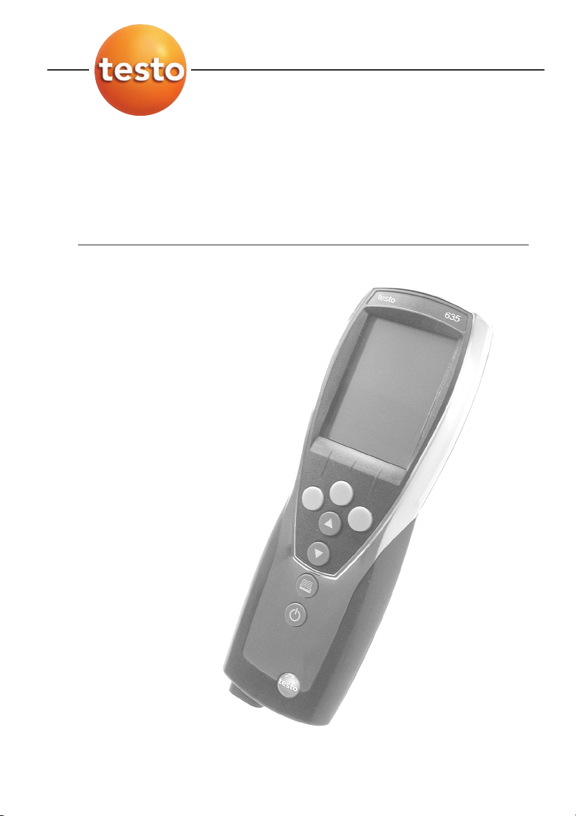
Humidity/temperature/pressure dew point measuring instrument
testo 635
Bedienungsanleitung de
Instruction manual en
Contents
General notes ....................................................32
1. Safety instructions..............................................34
2. Intended purpose ..............................................35
3. Product description............................................36
3.1 Display and control elements ........................................36
3.2 Interfaces ......................................................................38
3.3 Voltage supply ..............................................................38
4. Commissioning ..................................................39
5. Operation ..........................................................40
5.1 Connecting a probe ......................................................40
5.2 Switching on/off ............................................................40
5.3 Display light ..................................................................41
6. Setting the instrument ........................................42
6.1 Configuration menu ......................................................42
6.1.1 Profile..............................................................................42
6.1.2 Units ..............................................................................43
6.1.3 Device ............................................................................43
6.1.4 Probe..............................................................................45
6.1.5 Language........................................................................46
6.2 Main menu....................................................................47
6.2.1 Memory (635-2 only) ......................................................48
6.2.2 Measuring program (635-2 only) ....................................49
6.2.3 Mean ............................................................................50
6.2.4 Calculation ......................................................................51
6.2.5 Material ..........................................................................52
6.2.6 Cyclical Print (635-1 only) ..............................................53
7. Measuring ..........................................................54
8. Care and maintenance ......................................56
9. Questions and answers......................................57
10. Technical data ....................................................58
11. Accessories / spare parts ..................................59
www.GlobalTestSupply.com
Page 32
32
General notes
General notes
This chapter provides important advice on using this documentation.
The documentation contains information that must be applied if the product is
to be used safely and efficiently.
Please read this documentation through carefully and familiarise yourself with
the operation of the product before putting it to use. Keep this document to
hand so that you can refer to it when necessary.
Identification
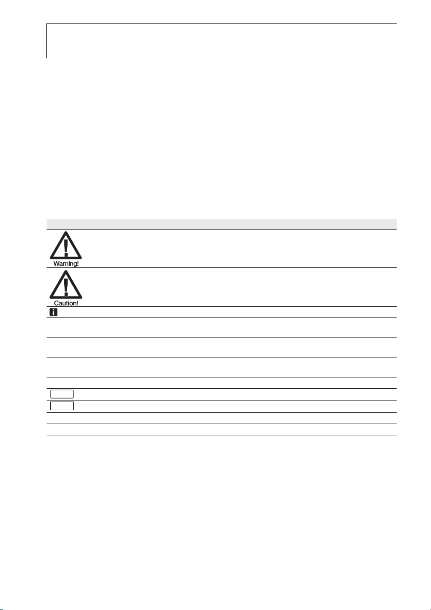
Representation Meaning Comments
Warning advice: Warning! Read warning advice carefully and take the precautionary measures
indicated! Serious physical injury could occur if you do not take the
precautionary measures indicated.
Warning advice: Caution! Read warning advice carefully and take the precautionary measures
Note Offers helpful tips and information.
±, 1, 2 Objective Denotes the objective that is to be achieved via the steps described.
Condition A condition that must be met if an action is to be carried out as
i, 1, 2, ... Step Carry out steps. Where steps are numbered, you must always follow
Text Display text Text appears on the instrument display.
Button
- Result Denotes the result of a previous step.
º Cross-reference Refers to more extensive or detailed information.
Control button Press the button.
Function button Press the button.
indicated! Slight physical injury or damage to equipment could occur
if you do not take the precautionary measures indicated.
Where steps are numbered, you must always follow the order given!
described.
the order given!
www.GlobalTestSupply.com
Page 33
General notes
33
Short form
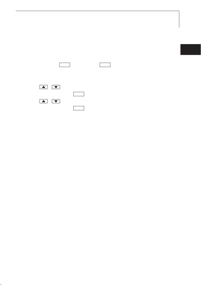
This document uses a short form for describing operating steps (e.g. calling up
a function).
Example: Calling up the “Instrument data” function
Short form: Device ¬¬Inst.data ¬ .
1) (2) (3) (4)
(
OKOK
Steps required:
1 Press / to select the Device function.
2 Confirm selection with .
3 Press / to select the Inst.data function.
4 Confirm selection with .
OK
OK
de
enfresitptsvnl????
www.GlobalTestSupply.com
Page 34

34
1. Safety instructions
1. Safety instructions
This chapter gives general rules which must be followed and observed if the
product is to be handled safely.
Avoid personal injury/damage to equipment
i Do not use the measuring instrument and probes to measure on or near live
parts.
i Never store the measuring instrument/measuring cells together with solvents
and do not use any desiccants.
Product safety/preserving warranty claims
i Operate the measuring instrument only within the parameters specified in the
Technical data.
i Always use the measuring instrument properly and for its intended purpose.
Do not use force.
i Do not expose handles and feed lines to temperatures in excess of 70 °C
unless they are expressly permitted for higher temperatures. Temperatures
given on probes relate only to the measuring range of the sensors.
i Open the instrument only when this is expressly described in the
documentation for maintenance or repair purposes.
Carry out only the maintenance and repair work that is described in the
documentation. Follow the prescribed steps when doing so. For safety
reasons, use only original spare parts from Testo.
Ensure correct disposal
i Take faulty rechargeable batteries/spent batteries to the collection points
provided for them.
i Send the product back to Testo at the end of its useful life. We will ensure
that it is disposed of in an environmentally friendly manner.
www.GlobalTestSupply.com
Page 35

1. Safety instructions
35
Instruments with radio module 915.00MHz FSK
Warning: Changes or modifications not expressly approved by the party responsible for compliance could void
the user's authority to operate the equipment.
This equipment has been tested and found to comply with the limits for a Class B digital device, pursuant to Part
15 of the FCC Rules.
These limits are designed to provide reasonable protection against harmful interference in a residential installation.
This equipment generates, uses and can radiate radio frequency energy and, if not installed and used in
accordance with the instructions, may cause harmful interference to radio communications.
However, there is no guarantee that interference will not occur in a particular installation. If this equipment does
cause harmful interference to radio or television reception, which can be determined by turning the equipment off
and on, the user is encouraged to try to correct the interference by one or more of the following measures:
· Reorient or relocate the receiving antenna.
· Increase the separation between the equipment and receiver.
· Connect the equipment into an outlet on a circuit different from that to which the receiver is needed.
· Consult the dealer or an experienced radio/TV technician for help.
Operation is subject to the following two conditions:
· this device may not cause harmful interference, and
· this device must accept any interference received, including interference that may cause undesired operation.
2. Intended purpose
This chapter gives the areas of application for which the product is intended.
Use the product only for those applications for which it was designed. Ask
Testo if you are in any doubt.
testo 635 is a compact measuring instrument for measuring temperature,
humidity and the pressure dew point.
The product was designed for the following tasks/applications:
· Measuring room climate
· Regulating and inspecting ventilation and air-conditioning installations
· Measuring the pressure dew point in compressed air systems
· Material moisture observation
The product should
· Areas at risk of explosion.
· Diagnostic measurements for medical purposes.
not
be used in the following areas:
de
enfresitptsvnl????
www.GlobalTestSupply.com
Page 36
36
3. Product description
3. Product description
This chapter provides an overview of the components of the product and their
functions.
3.1 Display and control elements
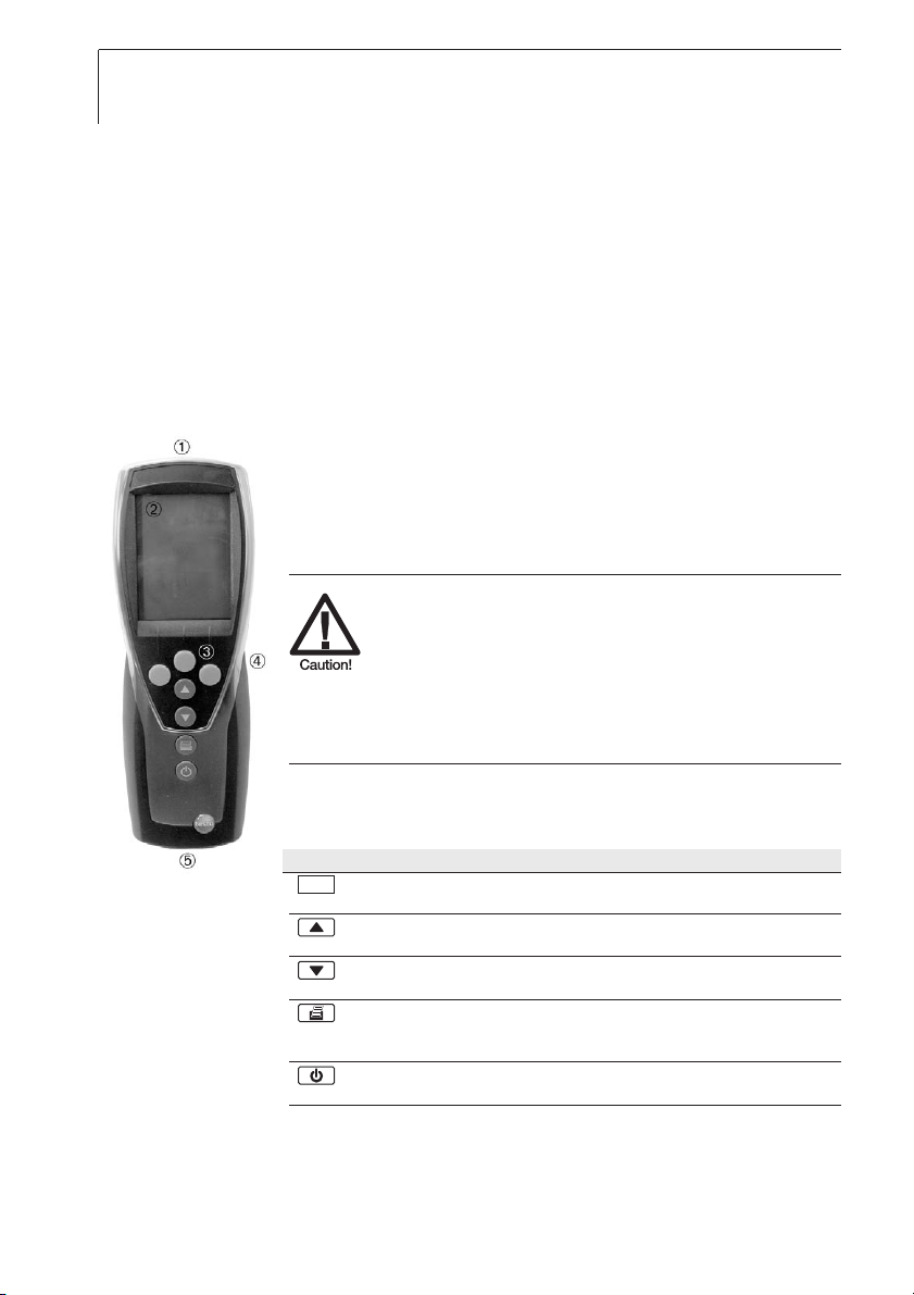
Overview
Infrared, USB interface
Display (light can be activated)
Control buttons
Rear: Battery and radio module compartment, holding
magnets
Strong magnets
Damage tto oother iinstruments!
i
Keep a safe distance from products which
could be damaged by magnetism (e.g.
monitors, computers, pacemakers, credit
cards).
Probe socket(s)
Button functions
Button Functions
Function button (3x): The function depends on the button assignment
at the time
Change display of the 1
In configuration mode: Increase value, select option
Change display of the 2
In configuration mode: Decrease value, select option
Print data
635-1 only: If the Cyclical Printing function is activated, the
programmed measuring program is started.
Switch instrument on, switch display light on/off;
switch instrument off (press and hold)
www.GlobalTestSupply.com
st
reading line
nd
reading line
Page 37
3. Product description
37
Function buttons (Function dependant on profile and setting)
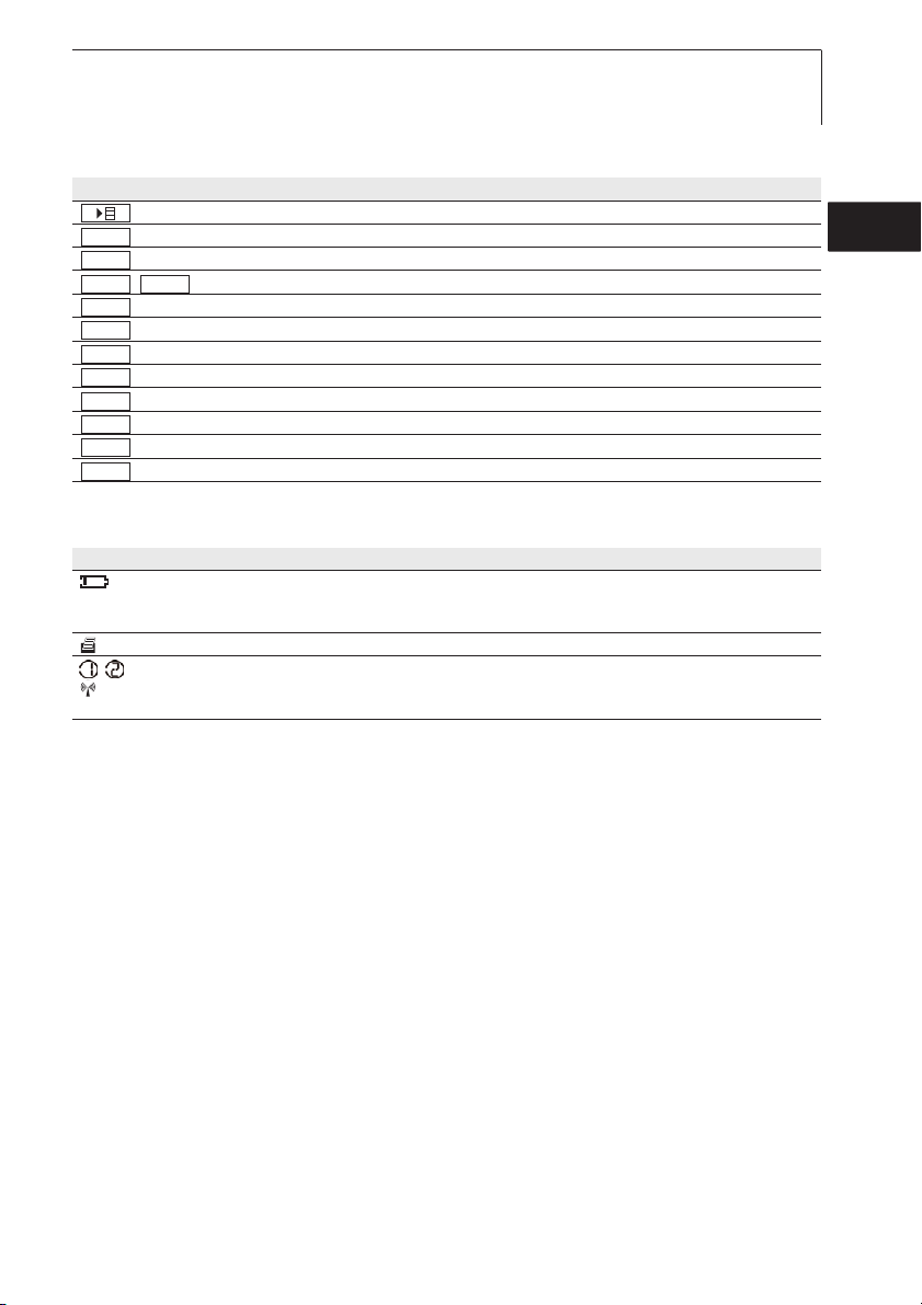
Button Functions
Open (main) menu
OK
ESC
ACTHold
/ Hold value/display current measurement value
Reset
Mean
Measp
Start
End
Save
Mat
Radio
Enter confirmation
Cancel
Reset max./min. values to current measurement value
Open menu item “Multi-point mean calculation“
Open menu item “Measuring program“ (635-2only)
Start test series (635-2 only)
End test series (635-2 only), End Cyclical Print (635-1 only)
Save values (635-2 only)
Open menu item “Material”
Open menu item “Radio”
Important displays
Display Meaning
Battery capacity (only for operation by battery/rechargeable battery):
· 4 segments in the battery symbol are lit: Instrument battery is fully charged
· No segments in the battery symbol are lit: Instrument battery is almost spent
(flashing) Print function: Data are sent to the printer
, Measurement channel no.: Channel 1, channel 2.
If a measurement channel is a radio channel, the radio symbol lights up as well as the
measurement channel no.
de
enfresitptsvnl????
www.GlobalTestSupply.com
Page 38

38
3. Product description
3.2 Interfaces
Infrared interface
Measurement data can be sent to a Testo printer via the infrared interface on
the head of the instrument.
USB interface
The mains unit (accessory part) can be connected to the head of the
instrument via the USB interface to power the instrument.
Instruments with a memory: Measurement/instrument data can be exchanged
with a PC via the USB interface.
Probe socket(s)
Plug-in measuring probes can be connected via the probe socket(s) on the
base of the instrument. The instrument is a HighPower device, possibly an
additional USB-Hub is required!
Radio module (accessory part)
Radio probes may only be used in countries in which they have been Type
Approved (see application information of the radio probe).
Up to three radio probes can be connected via the radio module.
3.3 Voltage supply
Voltage is supplied via three mignon batteries (included in delivery) or
rechargeable batteries or through a mains unit (accessory part). It is not
possible to charge rechargeable batteries in the instrument.
When operating the instrument with the mains unit, insert batteries in order
to avoid switching off the instrument in case of a power interruption.
www.GlobalTestSupply.com
Page 39

4. Commissioning
39
4. Commissioning
This chapter describes the steps required to commission the product.
Inserting bbatteries/rechargeable bbatteries aand aa rradio mmodule ((accessory
²
part):
1 Undo the two screws on the rear of the instrument and lift off the battery
compartment cover.
2 Insert batteries/rechargeable batteries (3x mignon) into the battery
compartment. Observe the polarity!
3 Push the radio module (accessory part) into the radio module
compartment until it engages in place. Note the guide groove.
4 Replace the battery compartment cover, press down and secure by
tightening the two screws.
de
enfresitptsvnl????
www.GlobalTestSupply.com
Page 40

40
5. Operation
5. Operation
This chapter describes the steps that are executed frequently when using the
product.
5.1 Connecting a probe
Plug-in probes
Plug-in probes must be connected before the measuring instrument is
switched on so that they are recognised by the instrument.
i Insert the connector of the probe into the probe socket of the measuring
instrument.
Radio probes
Radio probes may only be used in countries in which they have been Type
Approved (see application information of the radio probe).
A radio module (accessory part) is required for the use of radio probes. The
radio module must be connected before the measuring instrument is switched
on so that it is recognised by the measuring instrument.
Each radio probe has a probe ID (identification number) which must be set in
configuration mode.
º See chapter PROBE, p. 45.
5.2 Switching on/off
Switching tthe iinstrument oon:
²
i Press .
- Measurement view is opened: The current reading is displayed, or
---- lights up if no reading is available.
Instruments with a memory: The activated location is displayed
(topmost line).
-oor-
The instrument is switched on for the first time, a reset was carried out or
the power supply was interrupted for a lengthy period of time:
- The Language function is opened.
º See the chapter
LANGUAGE, p. 46.
www.GlobalTestSupply.com
Page 41
Switching tthe iinstrument ooff:
²
i Press and hold (for approx. 2s) until the display goes out.
5.3 Display light
Switching tthe ddisplay llight oon/off:
²
The instrument is switched on.
i Press .
5. Operation
41
de
enfresitptsvnl????
www.GlobalTestSupply.com
Page 42
42
6. Setting the instrument
6. Setting the instrument
This chapter describes the steps that are required in order to adapt the
measuring instrument for specific measuring tasks.
6.1 Configuration menu
The basic settings for the measuring instrument are performed in the
configuration menu.
Opening tthe cconfiguration mmenu:
²
The instrument is in measurement view.
i Press and hold (approx. 2s) until config. is displayed.
Press to go one menu level back. To leave the configuration menu,
press several times until the instrument changes to measurement view.
6.1.1 Profile
ESC
ESC
The instrument has predefined measurement profiles that are tailored to
specific areas of application.
The profile setting influences the following points in measurement mode:
· Assignment of the function buttons
· Number of predefined functions
· Structure of the main menu
All functions are available in the standard profile. In the application-specific
measurement profiles, the available functions are reduced to only those that are
needed to ensure speedier access.
Setting aa pprofile:
²
The configuration menu is open, config. is displayed.
1 Profile ¬ .
2 Select the desired profile with / and confirm with .
OK
OK
www.GlobalTestSupply.com
Page 43
6. Setting the instrument
43
6.1.2 Units
Predefined systems and individual setting options:
Parameter ISO system US system Individual setting options
Temperature °C °F °C, °F
Pressure hPa inchH2O mbar, Pa, hPa, kPa, inchH2O
Setting uunits:
²
The configuration menu is open, config. is displayed.
1 Units ¬ .
2 Press / ISO/US (to set the system) or a parameter (to set
individually) and confirm with .
3 Set the system of units or the desired unit with / and confirm
with .
OK
OK
OK
6.1.3 Device
Instrument data
Displaying iinstrument ddata:
²
The configuration menu is open, config. is displayed.
1 Device ¬¬Inst.data ¬ .
- The firmware version and the serial number of the instrument are
displayed.
OKOK
de
enfresitptsvnl????
Date/Time
Setting tthe ddate/time:
²
The configuration menu is open, config. is displayed.
1 Device ¬¬date/time ¬ .
2 Use / to set the value for year and confirm with .
3 Set the other values as described in step 2.
www.GlobalTestSupply.com
OKOK
OK
Page 44
44
6. Setting the instrument
Battery type
To ensure that the battery capacity is displayed correctly, the battery type used
must be set.
Setting tthe bbattery ttype:
²
The configuration menu is open, config. is displayed.
1 Device ¬¬Bat-type ¬ .
2 Press / Battery or ReBa and confirm with .
OKOK
OK
Auto OFF
If Auto OFF is switched on, the instrument switches itself off automatically after
10min if no button is pressed. Exception: Cyclical printing (instruments without
a memory) or a measuring program (instruments with a memory) is active.
Switching AAuto OOFF oon/off:
²
The configuration menu is open, config. is displayed.
1 Device ¬¬Auto OFF ¬ .
2 Press / to select On or Off and confirm with .
OKOK
OK
Reset
When a reset is carried out, the instrument is reset to the default settings, all
settings/data are deleted. Exception: Language, Date/Time.
Resetting:
²
The configuration menu is open, config. is displayed.
1 Device ¬¬reset ¬ .
2 Reset with or cancel the reset with .
OKOK
ESCOK
Setting min. / max. printing function
If pr MinMaxAuto is activated, minimum and maximum values are also printed
with the measurement readings.
Switching ooff ppr MinMax:
²
The configuration menu is open, Config. is displayed.
1 Device ¬¬pr MinMax ¬ .
2 Choose On or Off with / and confirm with .
www.GlobalTestSupply.com
OKOK
OK
Page 45
6. Setting the instrument
45
6.1.4 Probe
RadioC
Radio probes may only be used in countries in which they have been Type
Approved (see application information of the radio probe).
A radio module (accessory part) is required for the use of radio probes. The
instrument can establish a connection with a maximum of three radio probes.
Each radio probe has a probe ID (RF ID). This consists of the last 3 digits of the
serial no. and the position of the slide switch (H or L) in the radio probe.
Setting uup aa rradio pprobe:
²
A radio module (accessory part) is inserted in the instrument.
º See chapter COMMISSIONING, p. 39.
The configuration menu is open, config. is displayed.
The radio probe is switched on and the transfer rate is set to 2 readings
per second (see the advice on using the radio probe).
1 Probe ¬¬RadioC ¬ .
2 Press / to select the desired channel no. for the radio probe (P. 1 ,
P. 2 or P. 3 ) and confirm with .
- The instrument searches for switched-on radio probes in the receiving
range.
- The probe IDs of the radio probes found are displayed.
OKOK
OK
de
enfresitptsvnl????
If no radio probes were found, this may be because of the following:
· The radio probe is not switched on or the battery of the radio probe is
spent.
· The radio probe is outside the range of the measuring instrument.
· Sources of interference are influencing the radio transmission (e.g.
reinforced concrete, metal objects, walls or other barriers between
transmitter and receiver, other transmitters of the same frequency,
strong electromagnetic fields).
i If necessary, rectify the possible causes of the fault in radio
transmission.
Alternatively, the probe ID can also be entered manually.
MAN
i ¬ Press / to enter the probe ID.
www.GlobalTestSupply.com
Page 46
46
6. Setting the instrument
3 Press / to select the probe that is to be assigned to the chosen
channel no.
4 Assign the radio probe to the chosen channel no. with or exit the
function with , without changing the probe configuration. .
ESC
OK
Humidity probe calibration
This function is only available if a humidity probe is plugged in.
The calibration values can be reset to the default settings (Reset). A 2-point
calibration can be performed.
Resetting tthe ccalibration vvalues:
²
The configuration menu is open, config. is displayed.
1 Probe ¬¬Calibr. ¬ .
2 Press / to select Reset and confirm by pressing twice.
OKOK
OK
- The calibration values are reset to the default settings.
Calibrating:
²
The configuration menu is open, config. is displayed.
1 Probe ¬¬Calibr. ¬ .
OKOK
2 Press / to select calibration point P1 or P2 and confirm by
pressing twice.
OK
3 Put the humidity probe into the reference medium and wait for the
equalisation period to elapse.
- The current humidity reading and the calibration point (nominal value) are
displayed.
4 Start the calibration menu with .
5 Save calibration with or cancel calibration with .
OK
ESCOK
Te-Type
The probe characteristic curves stored in the instrument can be set for the
probe type used.
Setting pprobe ttype:
²
The configuration menu is open, Config. is displayed.
1 Probe ¬¬Te-Type ¬ .
2 Select the desired probe type with / and confirm with .
www.GlobalTestSupply.com
OKOK
OK
Page 47

6. Setting the instrument
47
6.1.5 Language
Setting tthe llanguage:
²
The configuration menu is open, config. is displayed.
1 Language ¬ .
2 Select the desired language with / and confirm with .
OK
OK
6.2 Main menu
Settings by which the measuring instrument can be adapted to the particular
measuring task are performed in the main menu.
The instrument has predefined measurement profiles that are tailored to
specific areas of application.
º See the chapter PROFILE, p. 42.
The profile setting influences the number of available functions and the
structure of the main menu.
The method described in this chapter for calling up the functions in the main
menu relates to the Standard profile setting. If a different profile is set, the
method for calling up individual functions may change or the function may
not be available in that particular profile. Some functions are only available
when a probe is connected or a wireless probe is switched on and
registered.
de
enfresitptsvnl????
Menu overview testo 635-1
Profile menu items Function
Standard Calc. Calculate water content , dew point, psychrometric temperature,
Material Activate material characteristic curves
cyc. Print De/activate cycle printing
Material Mean Time/point mean calculation
Calc. Calculate water content , dew point, psychrometric temperature,
cyc. Print De/activate cycle printing
RadioC Calc. Calculate water content , dew point, psychrometric temperature,
Material Activate material characteristic curves
cyc. Print De/activate cycle printing
www.GlobalTestSupply.com
De/activate differential temperature, set “Alpha” parameter
De/activate differential temperature, set “Alpha” parameter
De/activate differential temperature, set “Alpha” parameter
Page 48
48
6. Setting the instrument
Menu overview testo 635-2
Profile menu items Function
Standard Memory Activate/set measurement locality, print report, delete store
Meas Prog. Set/ de/activate measurement program
Mean Time/point mean calculation
Calc. Calculate water content , dew point, psychrometric temperature,
Material Activate material characteristic curves
Material Memory Messort aktivieren/anlegen, Protokolle drucken, Speicher löschen
Meas Prog. Set/ de/activate measurement program
Mean Time/point mean calculation
Calc. Calculate water content , dew point, psychrometric temperature,
RadioC Memory Activate/set measurement locality, print report, delete store
Meas Prog. Set/ de/activate measurement program
Mean Time/point mean calculation
Calc. Calculate water content , dew point, psychrometric temperature,
Material Activate material characteristic curves
Opening tthe mmain mmenu:
²
De/activate differential temperature, set “Alpha” parameter
De/activate differential temperature, set “Alpha” parameter
De/activate differential temperature, set “Alpha” parameter
The instrument is in measurement view.
i Press .
- Menu is displayed.
Press to go one menu level back. To leave the main menu, press
ESC
ESC
several times until the instrument changes to measurement view.
6.2.1 Memory (635-2 only)
Info
The free memory space is displayed
Location
The active location can be changed. Up to 99 locations can be created. The
numerical location designations (01-99) can be changed into any text (max.
10 characters) using the PC software.
www.GlobalTestSupply.com
Page 49
6. Setting the instrument
Changing aan aactive llocation:
²
The main menu is open, Menu is displayed.
1 Memory ¬¬Location ¬ .
2 Press / to select the location to be activated and confirm with
OK
.
OKOK
Protocol
Saved measurement protocols can be printed out on a Testo printer (accessory
part) via the infrared interface.
Printing aa mmeasurement pprotocol:
²
The main menu is open, Menu is displayed.
1 Memory ¬¬Protocol ¬ .
2 Press / to select the measurement protocol that is to be printed.
3 Press to start printing out the measurement protocol.
OKOK
Delete
The entire memory with all measurement protocols can be cleared.
Clearing tthe mmemory:
²
The main menu is open, Menu is displayed.
1 Memory ¬¬Delete ¬ .
2 Press to clear the entire memory.
OK
OKOK
49
de
enfresitptsvnl????
6.2.2 Measuring program (635-2 only)
A measuring program can be programmed and activated/deactivated:
Designation Description
Off Measuring program switched off: Readings can be stored manually
AUTO Automatic measuring program: The measuring cycle (min. 1s) and the number of
Deactivating aa mmeasuring pprogram:
²
The main menu is open, Menu is displayed.
1 Meas.Prog ¬ .
2 Press / to select Off and confirm with .
- The instrument returns to measurement view.
readings can be set freely.
OK
OK
www.GlobalTestSupply.com
Page 50
50
6. Setting the instrument
Programming aand aactivating tthe AAUTO mmeasuring pprogram:
²
The main menu is open, Menu is displayed.
1 Meas.Prog ¬ .
2 Press / to select AUTO and confirm with .
OK
OK
The measuring cycle is set in the order: hours /minutes/seconds.
3 Press / to set the measuring cycle in hours and confirm with
OK
.
4 Perform the setting for minutes and seconds as described in step 3.
5 Press / to set the number of readings and confirm with .
- The instrument returns to measurement view.
6.2.3 Mean
The menu item Mean value calculation is only available in the instrument
testo 635-2. In the instrument testo 635-1, the function Mean value
calculation is called up with the function button .
For carring out Mean value calculation see chapter Measuring, page 54.
Mean
OK
www.GlobalTestSupply.com
Page 51
6. Setting the instrument
51
6.2.4 Calculation
If calculation is switched on, additional parameters with calculated values can
be displayed from the readings of
additional measurement channels in measurement view.
Particular measurement channels must be available in order to perform the
calculation.
The following variables can be calculated:
· Water content (in percent by weight of the dry mass of the material)
· Dew point (below 0°Ctd/32°Ftd frost point temperatures are displayed)
· Psychrometric temperature
The heat transfer coefficient (alpha) required for calculating the U value can be
set.
It is also possible to calculate the difference between two measurement
channels (Delta). This is only possible if the selected measurement channels
have the same unit.
Activating/deactivating rreading ccalculation:
²
The main menu is open, Menu is displayed.
1 Calc. ¬ .
2 Press / to select the variable that is to be activated/deactivated
and confirm with .
3 Press / to select On (= activated) or Off (= deactivated) and
confirm with .
Entering tthe hheat ttransfer ccoefficient ((alpha):
²
OK
OK
OK
one
probe. These are then displayed as
de
enfresitptsvnl????
The main menu is open, Menu is displayed.
1 Calc. ¬¬alpha ¬ .
2 Press / to set the value and confirm with .
www.GlobalTestSupply.com
OKOK
OK
Page 52
52
6. Setting the instrument
Activating ddifferential ccalculation ((delta):
²
The instrument is in measurement view.
Differential calculation is performed with the parameters that are shown on
the display.
1 Press and to select the measurement channels from which the
difference is to be calculated.
2 Press to open the main menu.
3 calc. ¬ .
4 Press / to select Delta and confirm with .
OK
OK
6.2.5 Material
Measurement values (e.g. moisture content equilibrium) are sometimes related
to certain material characteristics. These are taken into account in the
measurement by means of recorded material characteristics. 10 materials with
typical material characteristics are recorded in the factory settings of the
instrument. The material can be reassigned and the characteristic curves
adapted using the PC software (635-2 only).
With an inserted stray field probe 0636 6160, the material characteristics
recorded in the probe are automatically called up. These are predefined and
cannot be changed via the PC software. See instruction manual for probe.
Factory default materials:
Display Material
a.screed Anhydrite screed
c.screed Cement screed
Limestone Limestone
Concrete Concrete
I. brick High-insulating brick
Activating aa mmaterial ccharacteristic ccurve:
²
The main menu is open, Menu is displayed.
1 Material ¬ .
2 Press / to select the desired material and confirm with .
OK
www.GlobalTestSupply.com
Display Material
sol. brick Solid brick
Hwlumber Hardwood lumber
Swlumber Softwood lumber
Gas concr Gas concrete
Chipboard Chipboard
OK
Page 53
6. Setting the instrument
53
6.2.6 Cyclical Print (635-1 only)
The Cyclical Print function can be activated/deactivated. A measuring program
for cyclical printing can be programmed. This enables readings (up to 999) to
be printed in a defined measuring cycle (min. 1min). The readings are sent to a
Testo printer.
Activating ccyclical pprinting/programming aa mmeasuring pprogram:
²
The main menu is open, Menu is displayed.
1 cyc.Print ¬ .
2 Press / to select Off (deactivated) or On (activated) and confirm
with .
The measuring cycle is set in the order: minutes/hours.
3 Press / to set the measuring cycle in minutes and confirm with
OK
.
4 Perform the setting for hours as described in step 3.
5 Press / to set the number of readings and confirm with .
- The instrument returns to measurement view.
- The measurement series is programmed and cyclical print can be
started with .
OK
OK
OK
de
enfresitptsvnl????
www.GlobalTestSupply.com
Page 54

54
7. Measuring
7. Measuring
This chapter describes the steps that are required to perform measurements
with the product.
Particular probes must be plugged in or switched on and registered (radio
probes) according to the variable that is to be measured.
Some probes require a warming-up phase until they are ready to measure.
The heat transfer coefficient (alpha) must be set before the U value can be
calculated.
º See CALCULATION, p. 51.
For calculating U value please refer to the documentation enclosed with the
temperature probe for calculating U value (0614 1635).
For simultaneous measurement of the material moisture via a stray field probe
and a radio humidity probe, the radio probe must first be logged on and the
corresponding material selected. Then the instrument must be switched off, the
stray field probe attached and, after switching on again, the material selected
for the stray field probe.
Taking aa mmeasurement:
²
The instrument is in measurement view.
The measuring program AUTO is not activated (635-2 only).
i Put the probe in position and take the readings.
Changing tthe uupper mmeasurement cchannel lline ddisplay:
²
i Press .
Changing tthe llower mmeasurement cchannel lline ddisplay, sshowing tthe
²
max./min. vvalue oof tthe vvariable iin tthe uupper mmeasurement cchannel lline:
i Press .
- The following are displayed in consecutive order:
· Available measurement channels
· Maximum value of the variable in the upper display line
· Minimum value of the variable in the upper display line
· Lower measurement line not shown
www.GlobalTestSupply.com
Page 55
7. Measuring
Resetting mmax./min. vvalues:
²
The minimum or maximum values of all measurement channels are reset.
1 Press several times until the maximum or minimum value is displayed.
2 Reset the max./min. values with .
Holding rreadings ((Profile SStandard oonly):
²
i Press .
i Press to change back to displaying the actual reading.
Saving rreadings ((635-22 oonly):
²
i Press .
Hold
Act
Save
Reset
- A measurement protocol with the readings of all available measurement
channels is created for the active location.
Timed mmean ccalculation:
²
The mean is formed as a moving mean value and individual values are not
displayed.
1 635-1: Press , 635-2: ¬ Mean ¬ .
2 Timed ¬ .
3 Press to start mean calculation.
Press to stop mean calculation.
OK
Start
End
OKMEAN
55
de
enfresitptsvnl????
Multi-ppoint mmean ccalculation:
²
The mean is formed as a moving mean value.
1 635-1: Press , 635-2: ¬ Mean ¬ .
2 Multi-poi ¬ .
3 Press to include readings.
Press to stop mean calculation.
Running tthe AAUTO mmeasuring pprogram ((635-22 oonly):
²
OK
Pick
End
The instrument is in measurement view and the AUTO measuring program
OKMEAN
is activated.
1 Start the measuring program with .
Start
- The measuring program starts. The readings are recorded.
- The measuring program continues to run until cancelled with or
End
until the end criterion is met (number of readings is reached or).
- The readings are saved in a protocol.
www.GlobalTestSupply.com
Page 56

56
8. Care and maintenance
Cyclical pprinting ((635-11 oonly):
²
The instrument is in measurement view and Cyclical Print is activated.
i Start cyclical printing with .
- The measuring program starts. The readings are transmitted to the
Testo printer.
- Measurement continues to run until cancelled with or until the
End
end criterion is met (number of readings is reached).
8. Care and maintenance
This chapter describes the steps that help to maintain the functionality of the
product and extend its service life.
Cleaning tthe hhousing:
±
i Clean the housing with a moist cloth (soap suds) if it is dirty. Do not use
aggressive cleaning agents or solvents!
Changing tthe bbattery/rechargeable bbattery:
±
Instrument is switched off.
1 Undo the two screws on the rear of the instrument and lift off the battery
compartment cover.
2 Remove spent batteries/rechargeable batteries and insert new
batteries/rechargeable batteries (3x mignon) into the battery
compartment. Observe the polarity!
3 Replace the battery compartment cover and tighten the two screws.
www.GlobalTestSupply.com
Page 57

9. Questions and answers
57
9. Questions and answers
This chapter gives answers to frequently asked questions.
Question Possible causes Possible solution
lights up · Instrument battery is almost spent. · Replace instrument battery.
Instrument switches ·
off automatically. · Residual capacity of the battery is too low. · Replace battery.
----- · Probe is not plugged in. · Switch instrument off, connect probe
Display:
uuuuu · Permitted measuring range · Keep to permitted measuring range.
Display:
ooooo · Permitted measuring range · Keep to permitted measuring range.
Display:
Instrument settings are · Power supply was interrupted for a · Re-enter instrument settings.
no longer correct long time.
If we are unable to answer your question, please contact your dealer or Testo
Customer Service. Contact details can be found on the guarantee card or on
the Internet under
Auto Off function is switched on. · Switch function off.
· Radio contact with radio probe is · Switch radio probe on, if necessary
interrupted. register radio probe again.
· Probe break. · Please contact your dealer
was undershot.
was exceeded.
www.testo.com
.
and switch instrument back on again.
or Testo Customer Service.
de
enfresitptsvnl????
www.GlobalTestSupply.com
Page 58

58
10. Technical data
10. Technical data
Measuring ranges and accuracies
Parameter/Probe type Measuring range Accuracy (± 1 Digit) Resolution
Temperature/ -200...+1370°C (Type K) ±0.3°C (-60.0...+60.0 °C) 0.1°C
Type K/T -200...+400°C (Type T) ±0.5% of reading (rest of range)
Relative humidity/ 0...+100%RH Depends on probe 0.1%RH
humidity probe
Pressure/absolute 0...+2000hPa Depends on probe 0.1hPa
pressure probe
Further instrument data
Characteristic Value
Probe connections 1x Omega TC socket, 1x Mini-DIN socket, radio module (accessory)
Memory 635-2 only: max. 99 locations, up to 10000 readings (depending on number of
Battery life 200h
Power supply 3x mignon battery (included in delivery)/rechargeable battery or mains unit
Housing material ABS/TPE/metal
Protection class IP65
Dimensions 225 x 74 x 46mm
Operating temperature range -20...+50°C
Storage temperature -30...+70°C
Measuring rate 2/s
EC Directive 89/336/EEC
Warranty Instrument: 2 years
-328...+2498°F (Type K) ±0.6°F (-76.0...+140.0°F) 0.1°F
-328...+752°F (Type T) ±0.5% of reading (rest of range)
locations, protocols, channels)
(accessory part)
www.GlobalTestSupply.com
Page 59

11. Accessories/spare parts
59
11. Accessories/spare parts
This chapter gives important accessory and spare parts for the product.
Name Part no.
Probes
Water-proof immersion/penetration probe, TC type K 0602 1293
Water-proof surface probe with widened measurement tip for smooth surfaces, TC type K 0602 1993
Robust affordable air probe, TC type K 0602 1793
Humidity/temperature probe, 12mm diameter 0636 9735
Handle for humidity/temperature probe, for connection to the measuring instrument,
including probe cable, for measures/calibrates of humidity probehead 0430 9735
Absolute pressure probe 2000hPa 0638 1835
Pressure dew point probe for measurements in compressed air systems 0636 9835
Temperature probe for calculating U value 0614 1635
Stray field probe 0636 6160
Miscellaneous
Plug-in mains unit, 5VDC, 500mA with European plug 0554 0447
External recharger incl. 4 Ni-MH rechargeable batteries with built-in, international plug,
100-240V, 300mA, 50/60Hz, 12VA/instrument 0554 0610
For a complete list of all accessories and spare parts, please refer to the
product catalogues and brochures or look up our website: www.testo.com
de
enfresitptsvnl????
www.GlobalTestSupply.com
Page 60

testo AG
Postfach 11 40, 79849 Lenzkirch
Testo-Straße 1, 79853 Lenzkirch
Telefon: (07653) 681-0
Fax: (07653) 681-100
E-Mail: [email protected]
Internet: http://www.testo.com
www.GlobalTestSupply.com
www.testo.com
0977.6350/05/T/dr/07.05.2008
 Loading...