

Page 1
testo 6351 · differential pressure transmitter
P2A software · Parameterizing, adjusting and analyzing
software
Instruction manual
Page 2

2
Page 3

1 Safety and the environment
Pos: 1 /TD/Überschriften/MUF/Sicherheit und Umwel t @ 3\mod_1234793958627_79.doc @ 26223 @ 1
1 Safety and the environment
Pos: 2 /TD/Sicherheit und Umwelt/Sicherheit gewähr lei s ten/MUF 63xx/Elektrische Gefahren vermeiden @ 3\ mod_ 1234 794609299_79.doc @ 26280 @ 5
Avoiding electrical hazards
> Never use the instrument and connected probes to measure on
or near live parts!
> Damaged mains cables must only be replaced by authorized
personnel.
> Only have the transmitter wired and connected by authorized
personnel with the voltage disconnected.
> You must always comply with the regulations applicable in your
Pos: 3 /TD/Sicherheit und Umwelt/Sicherheit gewähr lei s ten/MUF 63xx/Personen- und Sachschäden vermeiden @ 3\ mod_1234794744768_79.doc @ 26299 @ 5
country for opening and repairing electrical equipment.
Avoiding personal injury and damage to equipment
> Installation, setting and calibration work must only be carried
out by qualified and authorized personnel!
> Only open the instrument when this is expressly described in
the instruction manual for installation, maintenance or repair
purposes.
> Observe the permissible storage, transport and operating
Pos: 4 /TD/Sicherheit und Umwelt/Sicherheit gewähr lei s ten/Nicht mit Lösungsmitteln lagern @ 0\mod_11756923 75179_79.doc @ 583 @
temperature.
> Do not store the product together with solvents. Do not use any
Pos: 5 /TD/Sicherheit und Umwelt/Sicherheit gewähr lei s ten/MUF 63xx/Bei Wartung MUF nicht zur Regelung verwende n @ 3\ mod_1234794852377_79.doc @ 26318 @
desiccants.
> Do not use the instrument for control purposes at the same time
Pos: 6 /TD/Sicherheit und Umwelt/Sicherheit gewähr lei s ten/Produkt bestimmungsgemäß verwenden @ 0\mod_11737 81261848_79.doc @ 386 @
as operating or servicing the transmitter.
> Only operate the product properly, for its intended purpose and
within the parameters specified in the technical data. Do not
Pos: 7 /TD/Sicherheit und Umwelt/Sicherheit gewähr lei s ten/Nur beschriebene Wartungsarbeiten durchf ühren @ 0\mod_1175692705195_79.doc @ 601 @
use any force.
> Carry out only the maintenance and repair work on this
instrument that is described in the documentation. Follow the
prescribed steps exactly. Use only original spare parts from
Pos: 8 /TD/Sicherheit und Umwelt/Sicherheit gewähr lei s ten/MUF 63xx/Fachpersonal @ 3\mod_1234794940409_7 9.doc @ 26337 @
Testo.
Any additional work must only be carried out by authorized
personnel. Otherwise testo will not accept any responsibility for the
proper functioning of the instrument after repair and for the validity
of certifications.
3
Page 4
2 About this document
Pos: 9 /TD/Überschriften/MUF/Umwelt schützen @ 3\mod_ 123 4858757571_79.doc @ 26363 @ 5
Pos: 10 /TD/Sicherheit und Umwelt/Umwelt schützen/Pr odukt entsorgen @ 0\mod_1173780307072_79.doc @ 357 @
Protecting the environment
> At the end of its useful life, send the product to the separate
collection for electric and electronic devices (observe local
Pos: 11 /TD/Überschriften/MUF/Zu diesem Dokument @ 3\mod_ 1234793991331_79.doc @ 26242 @ 1
2 About this document
Pos: 12 /TD/Sicherheit und Umwelt/Zu diesem Dokument/Ver wendung (Standard) @ 0\mod_1173775068554_79.doc @ 337 @ 5
regulations) or return the product to Testo for disposal.
Use
> Please read this documentation through carefully and
familiarize yourself with the product before putting it to use. Pay
particular attention to the safety instructions and warning advice
in order to prevent injuries and damage to the products.
> Keep this document to hand so that you can refer to it when
necessary.
> Hand this documentation on to any subsequent users of the
Pos: 13 /TD/Sicherheit und Umwelt/Zu diesem Dokument/Sy mbole und Schreibkonventionen/Warnhinweis W ARNUNG @ 2\mod_1207646966234_79.doc @ 14398 @
Pos: 14 /TD/Sicherheit und Umwelt/Zu diesem Dokument/Sy mbole und Schreibkonventionen/Warnhinweis VORSIC HT @ 2\mod_1207651416515_79.doc @ 14416 @
Pos: 15 /TD/Sicherheit und Umwelt/Zu diesem Dokument/Sy m bo le und Schreibkonv. Software [Standard] @ 0\mod_11902 0333 2543_79.doc @ 4883 @ 5
product.
WARNING
CAUTION
Indicates potential serious injuries
indicates potential minor injuries
Symbols and writing standards
Representa-
Explanation
tion
Note: Basic or further information.
1. ...
2. ...
Action: more steps, the sequence must be
followed.
> ... Action: a step or an optional step.
- ... Result of an action.
Menu
[OK]
Elements of the program interface.
Buttons of the program interface.
... | ... Functions/paths within a menu.
“...” Example entries
Pos: 16 /TD/--- Seitenwechsel --- @ 0\mod_1173774430601_0.doc @ 283 @
4
Page 5

3 Contents
Pos: 17 /TD/Überschriften/MUF/Inhalt @ 3\mod_123479 4019831_79.doc @ 26261 @ 1
3 Contents
1 Safety and the environment....................................................................3
2 About this document...............................................................................4
3 Contents...................................................................................................5
4 Transmitter...............................................................................................8
4.1. Specifications ..................................................................................8
4.1.1. Functions and use ...........................................................................................8
4.1.2. Scope of delivery .............................................................................................8
4.1.3. Accessories .....................................................................................................8
4.1.4. Technical data .................................................................................................9
4.1.5. Dimensions....................................................................................................12
4.2. Product description........................................................................13
4.2.1. At a glance.....................................................................................................13
4.2.2. Display and keypad........................................................................................14
4.2.3. Service interface............................................................................................15
4.2.4. Relay board (option) ......................................................................................15
4.2.5. Analog outputs...............................................................................................15
4.2.6. Parameters....................................................................................................15
4.2.7. Scaling .........................................................................................................16
4.2.8. Alarm handling...............................................................................................17
4.3. Commissioning..............................................................................18
4.3.1. Assembling the instrument.............................................................................18
4.3.1.1. Wall mounting ...................................................................................18
4.3.2. Connecting the instrument.............................................................................19
4.3.2.1. Overview of terminals........................................................................21
4.3.2.2. Connecting voltage supply and analog outputs.................................22
4.3.2.3. Connecting the relay outputs............................................................23
4.3.2.4. Plug-in connection option..................................................................26
4.3.2.5. Closing the instrument......................................................................27
4.3.3. Adjusting the instrument ................................................................................29
4.3.3.1. Analog output adjustment.................................................................29
4.3.3.2. n-point adjustment............................................................................30
4.4. Operation.......................................................................................31
4.4.1. Relationship between user menu and mini-DIN socket is active....................31
4.4.2. Key cover.......................................................................................................31
4.4.3. Password protection ......................................................................................32
4.4.4. Structure of user menu ..................................................................................32
4.4.5. Overview of the testo 6351 user menu...........................................................34
4.4.6. The individual main menus ............................................................................37
4.4.6.1. Editing main menu of channel 1........................................................37
4.4.6.2. Editing Main Menu Alarm..................................................................37
4.4.6.3. Editing Main Menu Settings ..............................................................39
5
Page 6

3 Contents
4.4.6.4. Editing Main Menu Analysis..............................................................42
4.4.6.5. Editing Message main menu.............................................................44
4.4.6.6. Calling up Main Menu Ident..............................................................45
4.4.6.7. Editing Main Menu Adjust.................................................................45
4.4.6.8. Editing Reset main menu..................................................................47
4.5. Status, warning and error messages ............................................47
4.5.1. Status messages...........................................................................................48
4.5.2. Warning messages........................................................................................49
4.5.3. Transmitter error messages...........................................................................50
4.5.4. Handling alarm messages .............................................................................50
4.5.5. Namur fault conditions...................................................................................51
4.6. Maintenance and cleaning............................................................52
4.6.1. Maintaining the instrument............................................................................. 52
4.6.2. Cleaning the instrument.................................................................................52
5 Parameterizing, adjusting and analyzing software (P2A software) . . 53
5.1. Specifications................................................................................53
5.1.1. Functions and use .........................................................................................53
5.1.2. System requirements..................................................................................... 54
5.1.3. Scope of delivery...........................................................................................54
5.2. First steps ..................................................................................... 55
5.2.1. Installing the software/driver.......................................................................... 55
5.2.1.1. Installing P2A software.....................................................................55
5.2.1.2. Installing USB driver.........................................................................55
5.2.1.3. P2A software upgrade......................................................................55
5.2.2. Starting the software......................................................................................55
5.2.2.1. Starting the program......................................................................... 55
5.2.2.2. Establishing a connection wi th the instrument...................................55
5.2.2.3. Activating the connection w ith the instrument...................................56
5.3. Using the software........................................................................56
5.3.1. User interface................................................................................................56
5.3.2. Editing instrument/parameter file ...................................................................59
5.3.2.1. Changing instrument/parameter file..................................................59
5.3.2.2. Saving parameters............................................................................66
5.3.2.3. Opening the parameter file............................................................... 67
5.3.2.4. Copying and pasting parameters......................................................67
5.3.2.5. Deleting instrument/parameter file....................................................68
5.3.2.6. Creating a new instrument file...........................................................68
5.3.3. Analyzing/testing the transmitter....................................................................68
5.3.3.1. Analyzing/testing the instrument....................................................... 68
5.3.3.2. Carrying out factory reset..................................................................69
5.3.3.3. Testing analog output.......................................................................69
5.3.3.4. Testing switch outpu t relays 1 to 4....................................................71
5.3.3.5. Displaying min./max. values..............................................................72
5.3.4. Adjusting the transmitter................................................................................73
5.3.4.1. n-point adjustment............................................................................73
5.3.4.2. Adjusting the analog output.............................................................. 74
6
Page 7

3 Contents
5.3.5. Transmitter history.........................................................................................75
6 Tips and assistance...............................................................................79
6.1. Questions and answers.................................................................79
6.2. Accessories and spare parts .........................................................79
6.2.1. Ordering options for testo 6351 transmitter (0555 6351)................................80
Pos: 18 /TD/--- Seitenwechsel --- @ 0\mod_1173774430601_0.doc @ 283 @
7
Page 8

4 Transmitter
Pos: 19 /TD/Überschriften/MUF/1 Messumformer @ 3\ mod_1234258401060_79.doc @ 23894 @ 1
4 Transmitter
Pos: 20 /TD/Überschriften/MUF/1.1/2.1/3.1 Leis tungsbeschreibung @ 3\mod_1234258595211_79.doc @ 23951 @ 2
4.1. Specifications
Pos: 21 /TD/Leistungsbeschreibung/Verwendung/ MUF63xx/MUF 635x @ 3\mod_1234444589072_79.doc @ 25059 @ 3
4.1.1. Functions and use
The testo 6351 transmitter is suitable for the following applications,
amongst others:
• Test benches
• Clean rooms
• Filling processes
• Complex room climate applications
• Monitoring flow velocities or volumetric flow rates in air
Pos: 22 /TD/Leistungsbeschreibung/Lieferu mfang/ MUF 63xx/MUF 63xx ohne Ethernet @ 3\mod_1234444980038_79. d oc @ 25098 @ 3
conditioning systems
4.1.2. Scope of delivery
The scope of delivery of the testo 6351 transmitter includes the
following:
• Key cover
• Rear panel bracket
• Instruction manual
• Calibration report
• CD-ROM with operating instructions (PDF), configuration files
for Ethernet module and P2A update (this can only be used in
conjunction with the P2A software, which has to be ordered
Pos: 23 /TD/Leistungsbeschreibung/Lieferu mfang/ MUF 63xx/Zubehör Übersicht 635x @ 3\mod_1236084601953 _79.doc @ 27292 @ 3
separately).
4.1.3. Accessories
The following accessories are available for the testo 6351
transmitter, amongst others:
• Mains unit
• P2A software (parameterizing, adjusting and analyzing
software)
8
• Assembly accessories
Information about accessories and their order numbers can
be found in Accessories and spare parts or on the
website at www.testo.com.
Page 9

Pos: 24 /TD/Leistungsbeschreibung/Technische Dat en/MUF 63xx/MUF 635x @ 3\mod_1236164155689_79.doc @ 27353 @ 3555 5555555555555555
4.1.4. Technical data
Parameter
• Differential pressure
4 Transmitter
Accuracy
The specifications are only valid if the positive pressure is
• ±0.8 % of measuring range final value, additional ±0.3 Pa
• T
applied at the positive pressure connection.
intrinsic error
K slope drift
1
= 0.03 % of measuring range per degree Kelvin of
deviation from nominal temperature 22 °C
• T
K zeroing drift
= 0 %, as zeroing with solenoid valve2
Measuring range, resolution and overload
Measuring range
Resolution Overload
depending on
resolution ordered
0 to 50 Pa 0.1 Pa 20,000 Pa
0 to 100 Pa 0.1 Pa 20,000 Pa
0 to 500 Pa 0.1 Pa 20,000 Pa
0 to 10 hPa 0.01 hPa 200 hPa
0 to 50 hPa 0.01 hPa 750 hPa
0 to 100 hPa 0.1 hPa 750 hPa
1
Measuring uncertainty in accordance with GUM: ±0.8 % of measuring range
final value ±0.3 Pa.
GUM (Guide to the Expression of Uncertainty in Measurement): ISO guideline for determining the
measuring uncertainty in order to render global measurement results comparable.
The following uncertainties are used during the inquiry:
• Hysteresis
• Linearity
• Reproducibility
• Adjustment area/factory calibration
2
Minor mixtures of the media may occur at the positive and negative pressure
• Test location
side due to the automatic zeroing cycle.
9
Page 10

4 Transmitter
Measuring range
depending on
resolution ordered
0 to 500 hPa 0.1 hPa 2500 hPa
0 to 1000 hPa 1 hPa 2500 hPa
0 to 2000 hPa 1 hPa 2500 hPa
-50 to 50 Pa 0.1 Pa 20,000 Pa
-100 to 100 Pa 0.1 Pa 20,000 Pa
-500 to 500 Pa 0.1 Pa 20,000 Pa
-10 to 10 hPa 0.01 hPa 200 hPa
-50 to 50 hPa 0.01 hPa 750 hPa
-100 to 100 hPa 0.1 hPa 750 hPa
-500 to 500 hPa 0.1 hPa 2500 hPa
-1000 to 1000 hPa 1 hPa 2500 hPa
-2000 to 2000 hPa 1 hPa 2500 hPa
Upon delivery and following a factory reset the readings are
shown in the display in the unit that was ordered via the
KMAT option Fxx, see Ordering options for testo 6351
transmitter (0555 6351), page 80.
Meas. cycle
• 1/sec
Resolution Overload
10
Interface
• Mini-DIN for P2A software (adjustment and parameterization
software)
• optional: Ethernet module
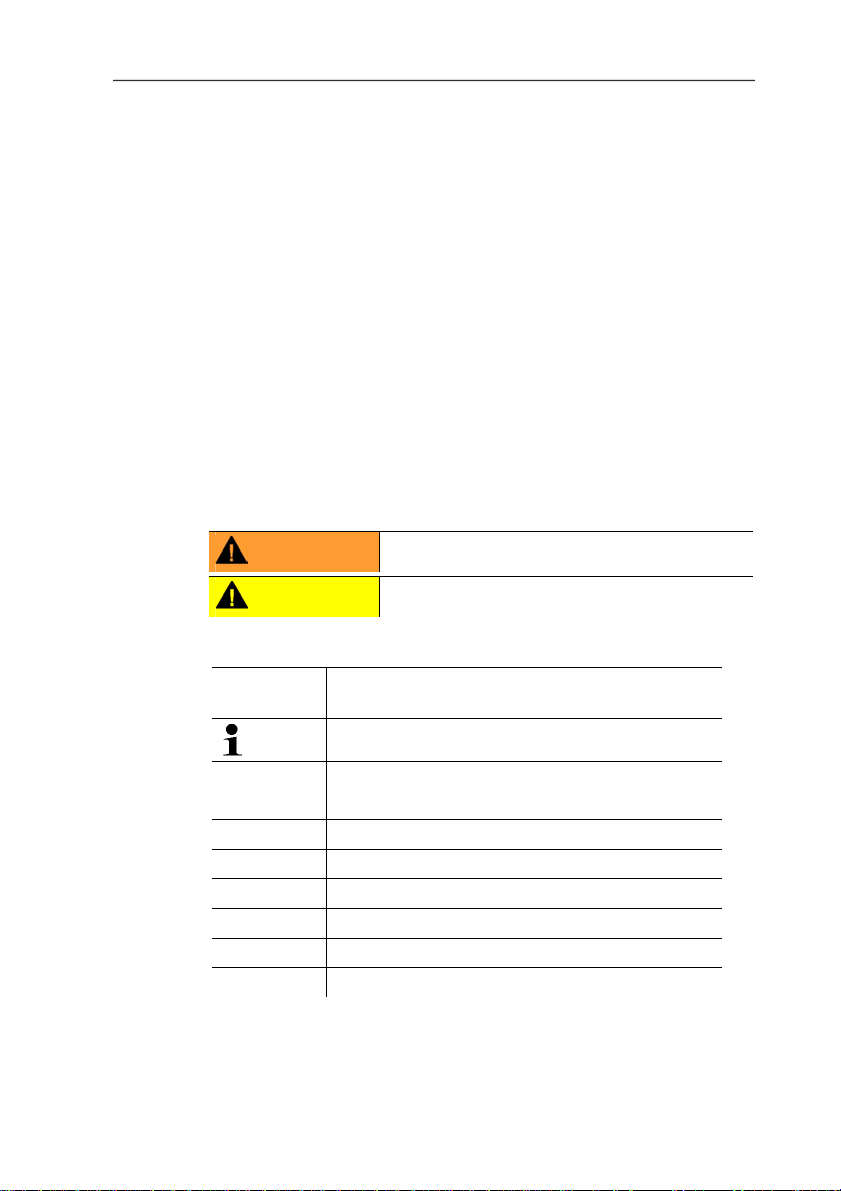
Voltage supply
• 4-wire (separate signal and supply lines): 20 to 30 V AC/DC,
300 mA power consumption
Maximum load
• 4-wire: 500 Ω (power output)
Page 11
4 Transmitter
Maximal load
• 4-wire: 10 kΩ (voltage output)
Analog output
• 0 to 1 V ± 1.5 mV (4-wire) or
• 0 to 5 V ± 7.5 mV (4-wire) or
• 0 to 10 V ± 15 mV (4-wire) or
• 0 to 20 mA ± 0.03 mA (4-wire) or
• 4 to 20 mA ± 0.03 mA (4-wire)
• T
= 0.05 %K of measuring range per degree Kelvin of
K
deviation from nominal temperature 22 °C
Resolution of analog output
• 12 bit
Relay
• 4 relays, 250 V AC/DC, 3 A (optional)
Display
• 2-line LCD with plain text line (optional)
Operating temperature
• -5 to 50 °C/23 to 122 °F
11
Page 12
4 Transmitter
Storage temperature
• -20 to 60 °C/-4 to 140 °F
Process temperature
• -20 to 65 °C/-4 to 149 °F
Housing, weight
• Plastic, 0.7 kg
• Optional Ethernet intermediate layer: 0.6 kg
Protection class
• IP 65 only if the transmitter is wired and/or sealing plugs are
Directives, standards and tests
• EC Directive: 2004/108/EC
Warranty
• Duration: 2 years
Pos: 25 /TD/Leistungsbeschreibung/Technische Dat en/MUF 63xx/MUF 63xx Abmessungen @ 3\mod_123445067149 4_79. doc @ 25194 @ 3
• Warranty conditions: see website www.testo.com/warranty
inserted
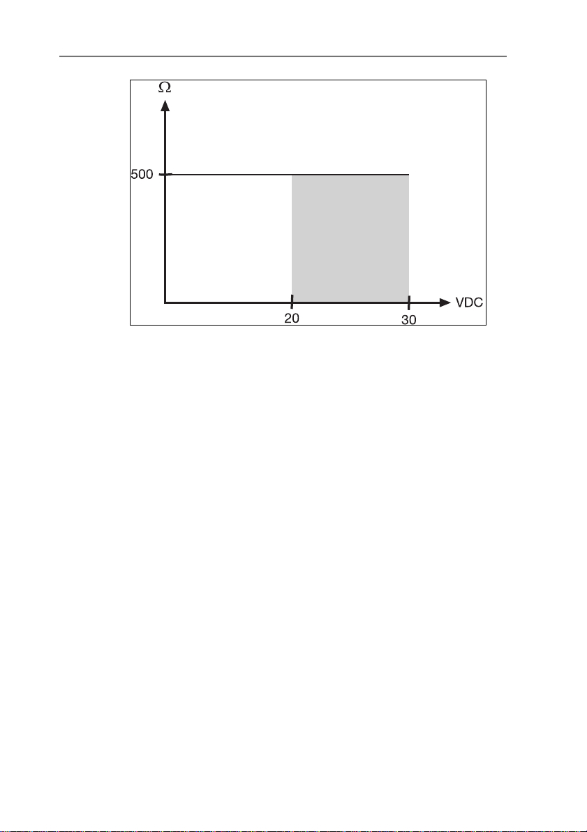
4.1.5. Dimensions
Dimensions in mm a b
with M20 cable couplings 144 147
With NPT cable coupling 144 144
With M plug-in connection 143
12
Page 13
Pos: 26 /TD/Überschriften/MUF/1.2/2.2 Produktb esc hreibung @ 3\mod_1234258723551_79.doc @ 24008 @ 2
4.2. Product description
Pos: 27 /TD/Produktbeschreibung/Übersicht/ MUF 63xx/Auf einen Blick 635x @ 3\mod_1236073473199_79.doc @ 27103 @ 3
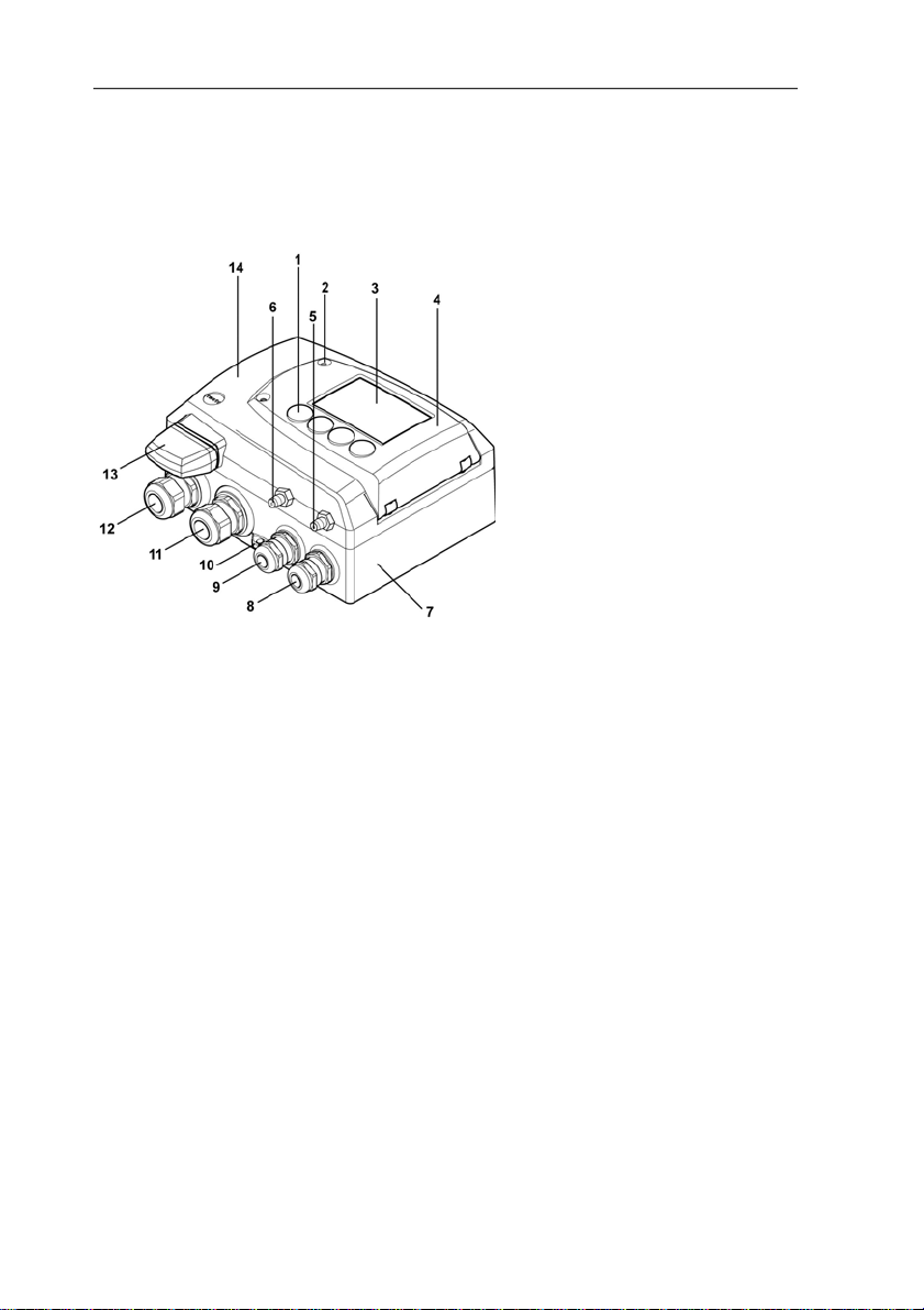
4.2.1. At a glance
1 Keys (only with optional
2 Service flap screw
3 Display (optio nal)
4 Service flap
5 Negative pressure
6 Positive pressu re connection,
7 Lo wer part of housing
8 M 16 x 1.5 screw
9 M 16 x 1.5 screw
10 Eyelet for measuring point
11 M 20 x 1.5 screw
12 M 20 x 1.5 screw
13 Adjusted probe plug (non-
14 Upper part of housing
* Alternatively, NPT cable
4 Transmitter
display)
connection (self-locking,
2 pcs.)
connection
marked with a red washer
connection*, e.g. analog
outputs
connection*, e.g. voltage
supply
panel
connection*, e.g. R3 and R4
relays
connection*, e.g. R1 and R2
relays
functional probe socket)
couplings or M plug-in
connections are available
13
Page 14
4 Transmitter
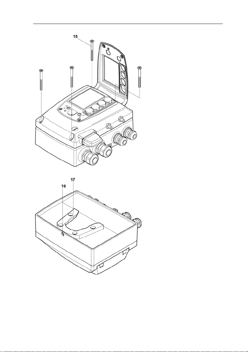
15 Housing screws
16 Hole for fastening to rear
panel bracket (M3 x 6 screw)
17 Plastic bracket for assembly
on rear panel
Pos: 28 /TD/Produktbeschreibung/Übersicht/ MUF 63xx/Display und Tastatur @ 3\mod_1234773965059_79.doc @ 25650 @ 3
4.2.2. Display and keypad
The display option allows operation of the testo 6351 transmitter via
the display and four keys.
14
Page 15

The LCD display consists of two 7-segment lines for displaying
readings and units and of an information line (for status messages,
for example).
The brightness and contrast of the display and the background
lighting (permanent or off) can be changed via the user menu or the
Pos: 29 /TD/Überschriften/MUF/1.2.x Servicesc hni ttstelle @ 3\mod_1237306891654_79.doc @ 29795 @ 3
4.2.3. Service interface
Pos: 30 /TD/Produktbeschreibung/Übersicht/ MUF 63xx/Serviceschnittstelle 635x @ 3\mod_12372173884 92_79.doc @ 29723 @
P2A software.
The parameterizing socket (mini-DIN) is located behind the service
Pos: 31 /TD/Produktbeschreibung/Übersicht/ MUF 63xx/Relaisplatine (Option) @ 3\mod_1234774184843_7 9.doc @ 25688 @ 3
flap as an interface to the P2A software.
4.2.4. Relay board (option)
This has a floating switch capacity of 250 V AC/3 A. The switching
limits and hysteresis as well as the function as relay for the
collective alarm can be set via the display or the P2A software.
Further features include:
• Function of changeover contacts (NC/NO contacts) freely
selectable
Pos: 32 /TD/Produktbeschreibung/Übersicht/ MUF 63xx/Analogausgänge 635x @ 3\mod_1234774510463_79.doc @ 25726 @ 3
• 12 terminals for a total of 4 relays.
If no relays are available, settings for monitoring limit values
or alarms can still be controlled via the display. The alarm
status will be shown on the display.
Only have the transmitter wired and connected by
authorized personnel with the voltage disconnected.
4 Transmitter
4.2.5. Analog outputs
As analog outputs, the testo 6351 has either
• 1 current output of 0 to 20 mA (4-wire)/4 to 20 mA (4-wire) or
Pos: 33 /TD/Produktbeschreibung/Übersicht/ MUF 63xx/Messgrößen 635x @ 3\mod_1234775082160_79.doc @ 25764 @ 3
• 1 voltage output of 0 to 1 V/0 to 5 V/0 to 10 V (4-wire)
4.2.6. Parameters
The following parameters are displayed:
• Differential pressure in Pa, hPa, kPa, mbar, bar, mmH
H
O, inch HG, kg/cm2, PSI
2
• Flow3 in m/s, ft/min
3
To prevent fluctuating flow rate values at the zero point (depressurized), the
flow rate values are only calculated as of differential pressures > 0.2 Pa or
15
O, inch
2
Page 16

4 Transmitter
•
Pos: 34 /TD/Produktbeschreibung/Übersicht/ MUF 63xx/Skalierung @ 3\mod_1234775406989_79.doc @ 25783 @ 3
• Volumetric flow rate
4.2.7. Scaling
There are three types of min./max. values:
1 The measuring range: The maximum sensor performance is in
this range. Values outside of the measuring range are displayed
via messages, for example. Measuring range, see table
(below).
2 Standard scaling: The output signals are assigned to this
measuring range as standard:
◦ during delivery if no entries are made in the order code
◦ after exchanging the unit, the measuring range recorded in
Pos: 35 /TD/Produktbeschreibung/Übersicht/ MUF 63xx/Tabelle Skalierung MUF 635x @ 3\mod_1236343891632_ 79. doc @ 27483 @
the instrument is applied as standard.
The transmitter even retains its scaling with the voltage
disconnected.
Measuring range, see table (below).
3 The maximum settings for the manual scaling
◦ The maximum limits can be calculated as follows:
X = difference between MIN. and MAX. value of the
standard scaling
(Max. value of standard) + (50 % of X)
(Min. value of standard) - (50 % of X)
◦ It is thus possible to scale beyond the measuring range, e.g.
for the adjustment of the scaling limits to standard values of
a PLC.
With the alarm definition, however, the physical measuring
range limits are decisive.
Measuring
range/standard scaling
0 to 50 Pa -25 to 75 Pa
0 to 100 Pa -50 to 150 Pa
0 to 500 Pa -250 to 750 Pa
0 to 10 hPa -5 to 15 hPa
4
in m3/h, l/min, Nm3/h, Nl/min
Maximum scaling
> 0.1 % of the respective measuring range (whichever is the greater). With
smaller differential pressures, the flow rate value remains at 0.00 m/s.
4
Calculated
16
Page 17

4 Transmitter
Measuring
range/standard scaling
0 to 50 hPa -25 to 75 hPa
0 to 100 hPa -50 to 150 hPa
0 to 500 hPa -250 to 750 hPa
0 to 1000 hPa -500 to 1500 hPa
0 to 2000 hPa -1000 to 3000 hPa
-50 to 50 Pa -100 to 100 Pa
-100 to 100 Pa -200 to 200 Pa
-500 to 500 Pa -1000…1000
-10 to 10 hPa -20 to 20 hPa
-50 to 50 hPa -100 to 100 hPa
-100 to 100 hPa -200 to 200 hPa
-500 to 500 hPa -1000 to 1000 hPa
-1000 to 1000 hPa -2000 to 2000 hPa
-2000 to 2000 hPa -4000 to 4000 hPa
Pos: 36 /TD/Produktbeschreibung/Übersicht/ MUF 63xx/Alarmbehandlung @ 3\mod_1234776787635_79.doc @ 25821 @ 3
4.2.8. Alarm handling
For upper and lower alarm limits, individual alarms as well as
collective alarms can be specified. If the collective alarm function is
activated, an alarm is triggered as soon as the alarm limit of an
alarm is exceeded, if this alarm is assigned to the collective alarm.
The testo 6351 monitors limit values with the help of relays. If a
reading is outside the limit values, a relay to be specified by the
user is switched.
If the reading reverts to more than a specified hysteresis below or
above the limit value, the alarm is cancelled.
In addition, information about the occurrence of error/status
messages can be provided by means of a collective alarm relay,
see Status, warning and error messages, page 47
If multiple alarm messages are activated at the same time,
the last alarm is shown. If the alarm is cancelled again, the
previous messages are no longer shown.
Maximum scaling
17
Page 18
4 Transmitter
Pos: 37 /TD/Überschriften/MUF/1.3/2.3 Inbetri ebnahme @ 3\mod_1234258805768_79.doc @ 24027 @ 2
4.3. Commissioning
Pos: 38 /TD/Erste Schritte/MUF 63xx/Wandmontage 635 x_6321 @ 3\mod_1236065568006_79.doc @ 27063 @ 3455
4.3.1. Assembling the instrument
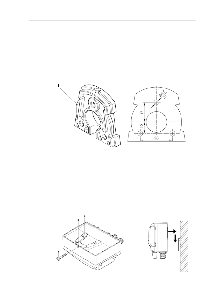
4.3.1.1. Wall mounting
Attaching rear panel bracket
1. Remove locking screw (see item (4) of drawing below) and
detach rear panel bracket from plastic bracket (see item (2) of
drawing below).
2. Hold rear panel bracket in assembly position and mark the three
drill holes.
3. Drill three holes (Ø 5 mm) and insert dowels where necessary.
4. Screw on rear panel bracket.
Remember that the clamping brackets (1) must face the wall.
Fastening instrument to rear panel bracket
18
Page 19
1. Slide plastic bracket (2) on the back of instrument onto rear
panel bracket until it engages (see arrows).
2. Insert screw (4) through hole (3) and screw into rear panel
Pos: 39 /TD/Erste Schritte/MUF 63xx/Gerät anschließ en @ 3\ mod_1234779466958_79.doc @ 25878 @ 35
bracket.
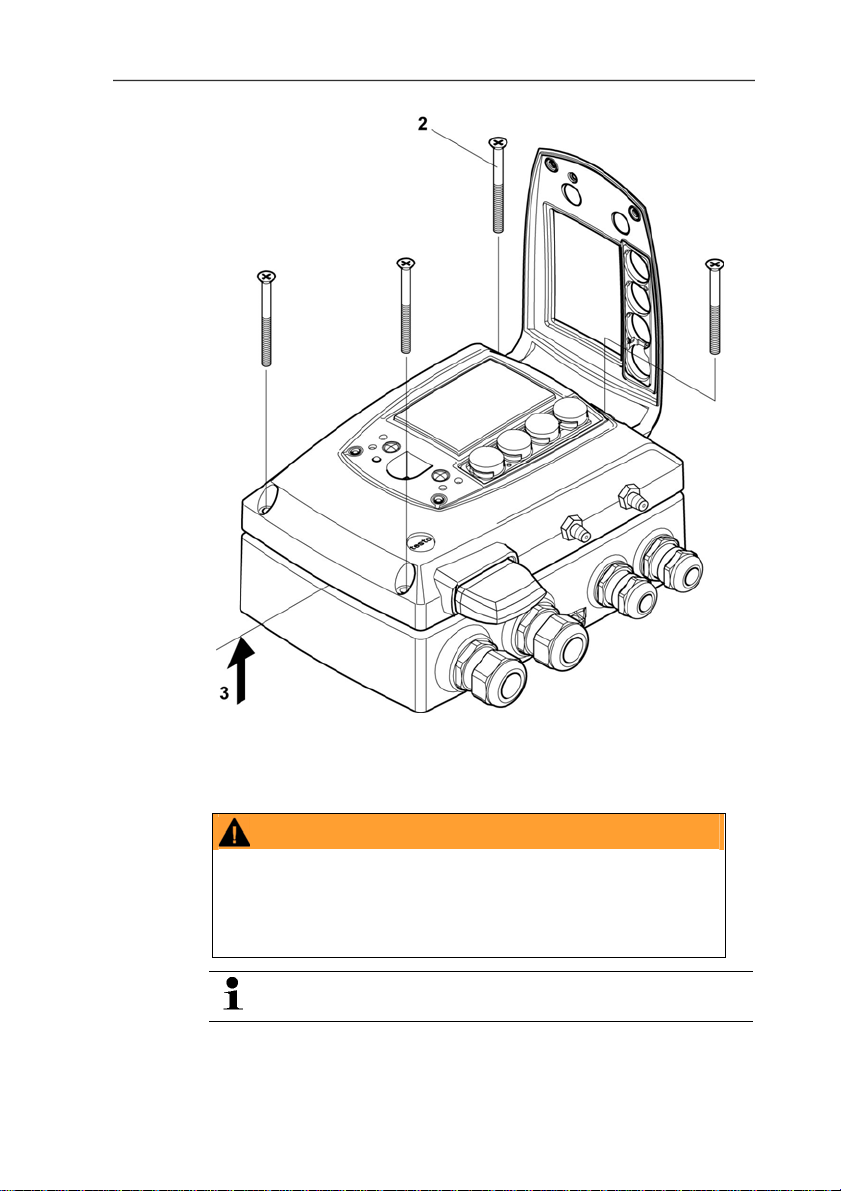
4.3.2. Connecting the instrument
4 Transmitter
Opening the instrument
1. Loosen screw connection (1) of service flap and open the flap.
19
Page 20
4 Transmitter
20
2. Loosen and remove housing screws (2).
3. Remove upper part of housing from lower part (3) and place on
a clean surface.
WARNING
Electrical voltage
Danger of injury!
> De-energize the mains connection before connecting the
transmitter.
Only have the transmitter wired and connected by
authorized personnel with the voltage disconnected.
Page 21
Pos: 40 /TD/Erste Schritte/MUF 63xx/Anschlussüber sicht 635x @ 3\mod_1234780293877_79.doc @ 25916 @ 4
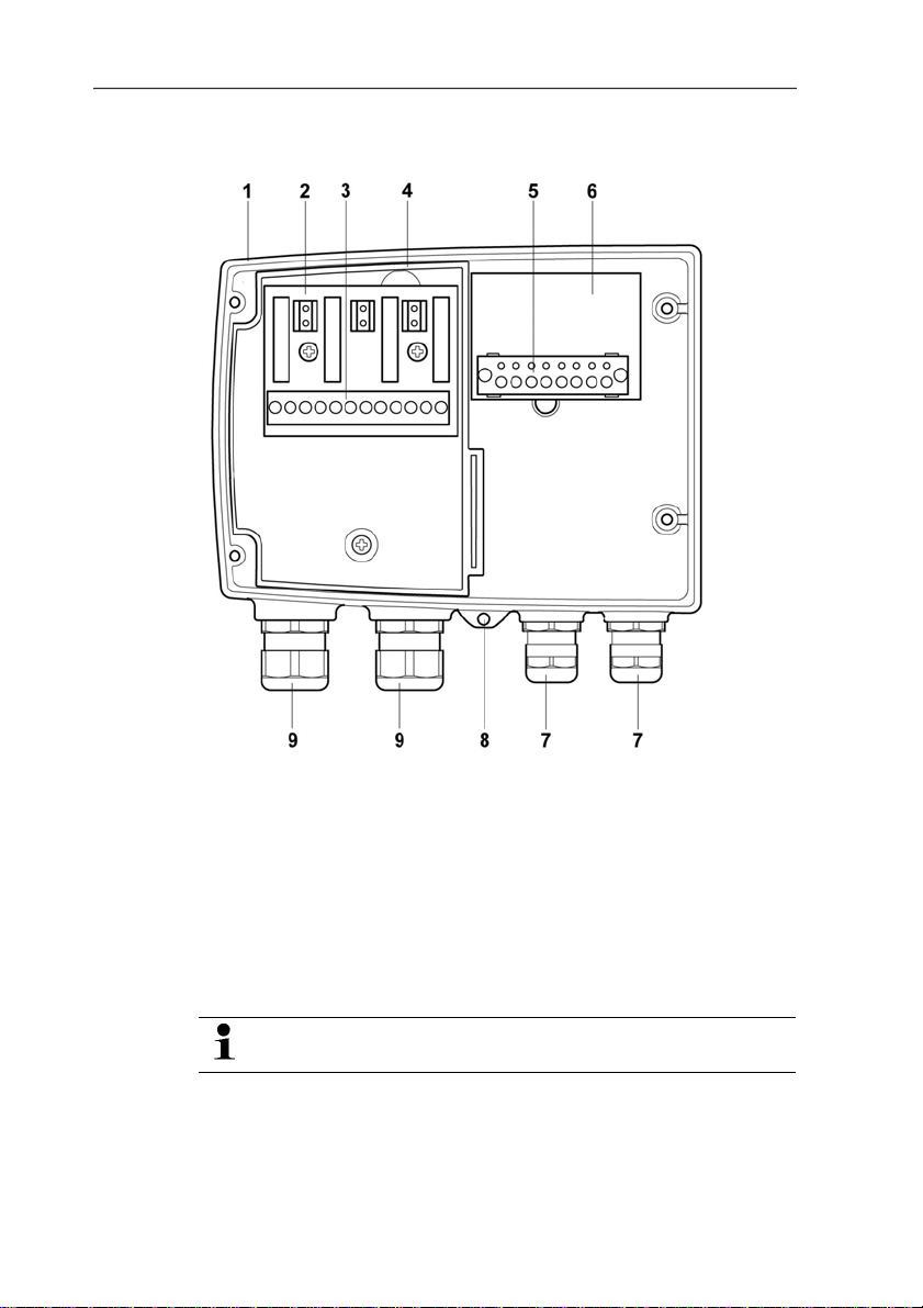
4.3.2.1. Overview of terminals
4 Transmitter
1 Lo wer part of housing 6 Terminal board
2 Relay b oard (option) 7 M 16 x 1.5 screw connection*
3 Relay termi nals
8 Eyelet for measuring point
panel
4 Insulating trough for relay
9 M 20 x 1.5 screw connection*
board
5 Terminal strip for voltag e
supply and analog outputs
* Alternatively, NPT cable
coupling or M plug-in
connection
The following description of the terminals refer to this
overview and its numbering.
21
Page 22
4 Transmitter
Pos: 41 /TD/Erste Schritte/MUF 63xx/Spannungsversor gung/Analogausgänge anschließen 635x @ 3\mod_1234 7861 77781_79.doc @ 25973 @ 45
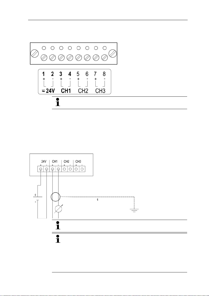
4.3.2.2. Connecting voltage supply and analog outputs
Terminal strip for voltage
supply and analog outputs,
item (5) of overview of
terminals, page 21
Channels 2 and 3 shown on the circuit board cannot be
used with this instrument.
1. Disconnect connector.
2. Strip the cable ends, clamp wire end ferrules on and screw
down onto voltage terminals.
3. Insert connector into socket.
Wiring diagram for 4-wire system (0 to 20 mA/4 to 20 mA/0 to
1 V/0 to 5 V/0 to 10 V)
1-channel
0 to 20 mA/4 to 20 mA
max. load per 500 Ω
0 to 1 V/0 to 5
V/0 to 10 V
Channels 2 and 3 shown on the circuit board cannot be
used with this instrument.
Requirement for the connecting cable of the supply:
• Insulated with cross-section of at least 0.25 mm²,
maximum 2.7 mm² without wire end sleeves.
• The supply line must be secured against exceeding 8 A.
• An OFF switch must be installed in an easily accessible
position close by and be marked as such.
22
Page 23
1. Disconnect connector.
2. Strip the cable ends, clamp wire end ferrules on and screw to
channel terminals as shown in diagram.
Pos: 42 /TD/Erste Schritte/MUF 63xx/Relaisausgänge a nschließen @ 3\mod_1234786460813_79.doc @ 25992 @ 455555
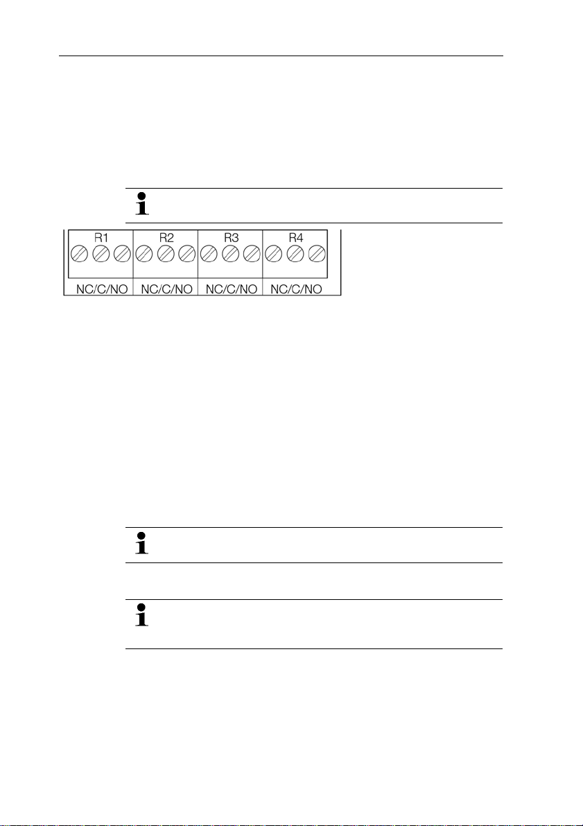
4.3.2.3. Connecting the relay outputs
3. Insert connector into socket.
Only have the transmitter wired and connected by
authorized personnel with the voltage disconnected.
There is the option of twelve terminals for a total of four relays. The
designations NC/C/NO (normally closed contact/root or
pin/normally open contact) are etched on the surface of the board.
Using PG screw connection
1. Feed connection cables for the relays through opened
M 20 x 1.5 screw connection (item (10) of overview of
terminals).
2. Strip cable ends and clamp on wire end ferrules.
3. Connect relays according to chosen function (NC/NO) (see
diagrams below; relay 1 is shown as an example of a
connection).
4 Transmitter
Relay terminal strip,
item (3) of overview of
terminals
Using plug-in connections (optional)
Only insert or disconnect the plug-in connection when the
voltage is disconnected.
4. Clean the connector of the probe line and the coupling of any
foreign matter.
Do not disconnect the connector of the probe line from the
instrument for extended periods to protect against
contamination.
23
Page 24
4 Transmitter
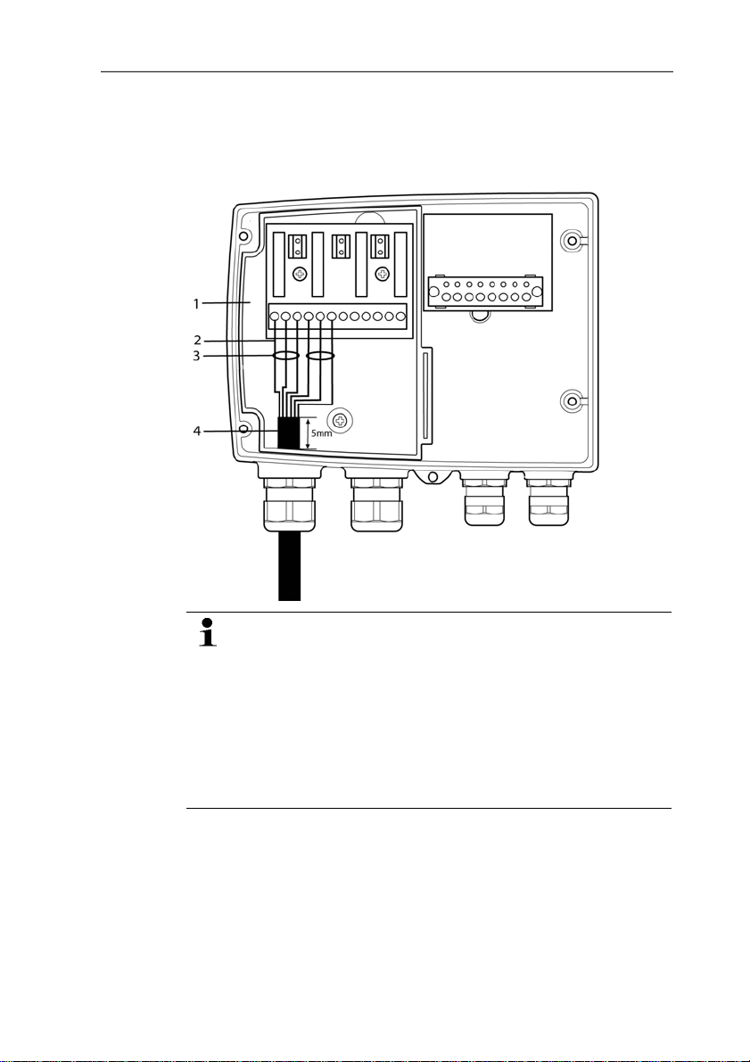
Connection note
• For the connection, a double-insulated mains cable
(sheathed cable) with a cross-section of at least
1.5 mm² must be used.
• Cable connection (2) may not be routed in a loop within
the tray (1).
• It is recommended that you always tie 3 cores to one
another using a cable tie (3).
• The insulation of the cable must be fed at least 5 mm
(4) into the tray.
24
Page 25
4 Transmitter
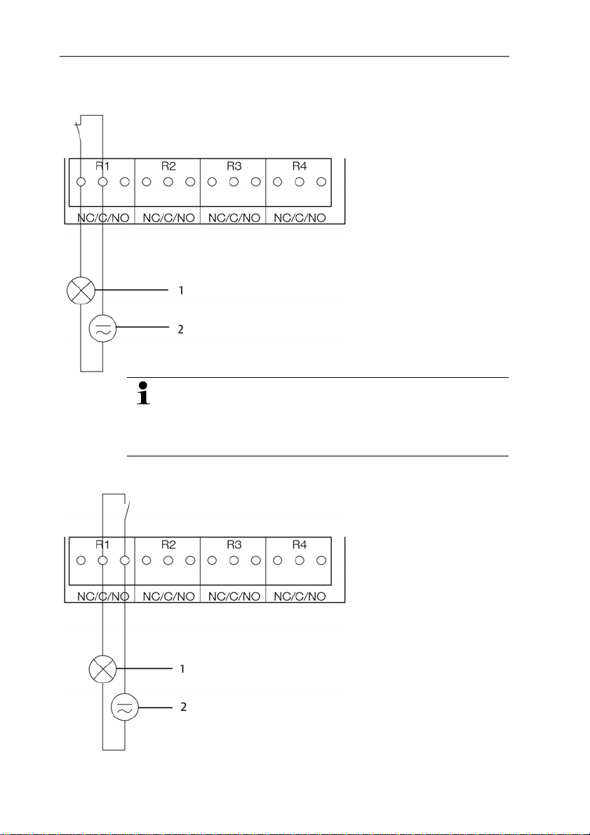
Use of relay as NC contact (NC = normally closed)
1 Alarm/status light
(example of installation)
2 250 V AC/DC, 3 A
The busy light (alarm/status light) is permanently on until
the relay opens or the circuit is interrupted. This circuit can
therefore be used to monitor the functionality of the alarm
circuit, as a cable break, for instance, is indicated by the
busy light going off.
Use of relay as NO contact (NO = normally open)
1 Alarm/status light
(example of installation)
2 250 V AC/DC, 3 A
25
Page 26
4 Transmitter
The busy light (alarm/status light) only comes on when the
relay is switched (closed). Monitoring the functionality of the
alarm circuit is therefore not possible with this switching
operation.
5. Close M 20 x 1.5 screw connection (item (9) in overview of
Pos: 43 /TD/Erste Schritte/MUF 63xx/Option Stecker verbindung 635x @ 3\mod_1237387714896_79.doc @ 30053 @ 45
terminals).
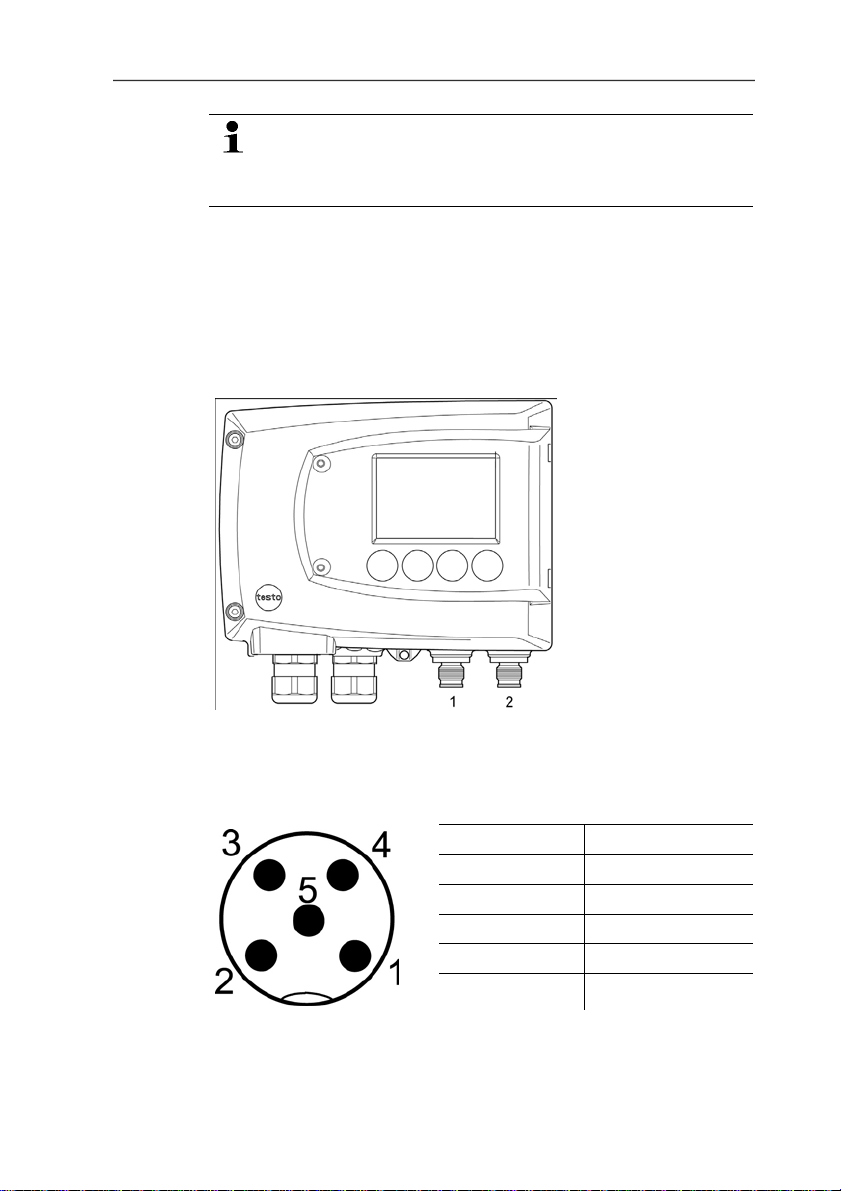
4.3.2.4. Plug-in connection option
As an option, the PG screw connections of the signal and supply
lines can be replaced with plug-in connections that are installed at
the housing, see item 1 and 2. The relay cabling occurs via
standard cable entries and PG screw connections.
26
Plug-in connections for power supply and channels
M12 plug-in connection (5-pin) socket (item 1)
View of the plug-in connections in the installed state from outside
PIN Assignment
1 V 242 V 24+
3 + Ch1
4 - Ch1
5 PE
Page 27

Pos: 44 /TD/Erste Schritte/MUF 63xx/Gerät schließen @ 3\ m od_ 1234788511529_79.doc @ 26030 @ 4
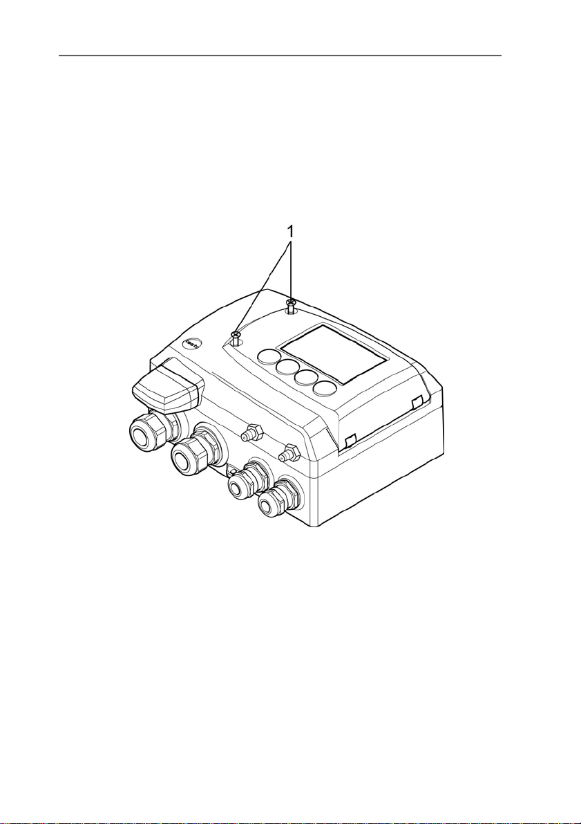
4.3.2.5. Closing the instrument
4 Transmitter
1. Place upper part of instrument on top of lower part (see arrow)
and fix in place with housing screws (1).
27
Page 28

4 Transmitter
Pos: 45 /TD/Überschriften/MUF/1.3.3 Gerät abgleic hen @ 3\mod_1236081099337_79.doc @ 27173 @ 3
2. Close the service flap and tighten screws (2).
28
Page 29

4.3.3. Adjusting the instrument
Pos: 46 /TD/Erste Schritte/MUF 63xx/Analogausgangs- Abgleich 635x @ 3\mod_1237373284088_79.doc @ 29825 @ 45
4.3.3.1. Analog output adjustment
The purpose of adjusting the analog outputs is to adjust the signal
chain from the digital signal (within the transmitter) to the analog
outputs. The signal type that was appointed for the transmitter is
adjusted respectively for each channel (e.g. 4 to 20 mA or 0 to 1 V,
etc.).
4 Transmitter
1 Status LED
2. Contact ch. 1+
3. Contact ch. 1-
4. Service interface
Adjusting analog output 1
✓ With testo 6351 with current output: Load of max. 500Ω is
connected to channel 1 (see Plug-in connections for power
supply and channels, page 26)
✓ A precise multimeter (minimum requirement: resolution 6.5
digits, at least 5-times more accurate than the 6351) is
available.
If only a simple multimeter is available, the analog output
must not be adjusted.
✓ The service flap is open.
1. Connect the inputs of the multimeter with the contacts (2) and
(3) for channel 1.
29
Page 30

4 Transmitter
2. Transfer the reference analog value measured with the
multimeter into the P2A software (see Adjusting the analog
output, page 74) or enter it via the user menu (see Performing
analog adjustment, page 45).
3. Disconnect connections between the multimeter and the
Pos: 47 /TD/Erste Schritte/MUF 63xx/n-Punkt-Abgleic h _635x @ 3\mod_1236352382511_79.doc @ 27522 @ 4
contacts of the testo 6351 and close the service flap.
4.3.3.2. n-point adjustment
With an n-point adjustment, the parameters at the 3-6
measurement points are adjusted to the reference value. The
reference conditions are obtained by using a precise pressure
sensor that should be 5-times more accurate than the transmitter.
1 Positive pressu re connection
2. Negative pressure connection
3. Pressure sensor
30
The number of measuring points is set to 3 by the factory
and can only be changed using the P2A software (see n-
point adjustment, page 73).
The n-point adjustment must always be carried out to its full
extent and in good time at all selected measurement points.
✓ A precise pressure sensor (5-times more accurate than the
transmitter, e.g. DPC precision pressure sensor from testo
industrial services) is available.
1. Connect the positive output of the pressure sensor (3) to the
positive pressure connection of the transmitter (1) and the
negative output of the pressure sensor (3) to the negative
pressure connection of the transmitter (2).
2. Transfer the reference pressure value created with the pressure
sensor into the P2A software (see n-point adjustment, page 73)
or enter it via the user menu (see Performing analog
adjustment, page 45).
3. Repeat step 2 for all of the measuring points.
4. Disconnect connections between the pressure sensor and the
pressure connections of the testo 6351.
Page 31

4 Transmitter
Pos: 48 /TD/Überschriften/MUF/1.4 Bedienung @ 3\mod_ 1234 443160034_79.doc @ 25001 @ 2
4.4. Operation
Pos: 49 /TD/Produkt verwenden/MUF 63xx/Zusammenhang Bedi enmenü – Mini DIN Buchse aktiv @ 3\mod_1234454016014_79. doc @ 25213 @ 3
4.4.1. Relationship between user menu and mini-DIN
socket is active
The testo 6351 can be parameterized using either the user menu or
the P2A software (see Parameterizing, adjusting and analyzing
software (P2A software) page 53).
The testo 6351 transmitter can only be operated via the
display and keypad if the display option is available.
If the testo 6351 is connected to the P2A software, the user
menu is blocked for the duration of the communication. The
message Service plug is shown in the display of the testo
6351. As soon as the P2A software is disconnected, the
Pos: 50 /TD/Produkt verwenden/MUF 63xx/Tastenblende @ 3\ m od_1 234454640248_79.doc @ 25232 @ 35
user menu is accessible again.
4.4.2. Key cover
To prevent unauthorized operation of the keys, the standard key
frame can be replaced with a key cover.
If the key cover has been assembled, the service flap must be
opened for operation.
31
Page 32

4 Transmitter
Pos: 51 /TD/Produkt verwenden/MUF 63xx/Passwortschu tz _635x @ 3\mod_1237383967006_79.doc @ 29969 @ 3
Attaching the key cover
✓ The service flap is opened, see Openi ng the instrument, page
19.
1. Unscrew screws (3) and remove key frame (2).
2. Insert key cover (1) into service flap and tighten screws (3).
3. Close and screw down the service flap.
4.4.3. Password protection
The user menu can be protected with a four-digit numerical code
(see Editing Main Menu Settings, page 39) so that access to the
user menu is denied to unauthorized persons not familiar with this
numerical code.
If the password protection is not to be used, the numerical code
Pos: 52 /TD/Produkt verwenden/MUF 63xx/Aufbau des Bedien menüs 635x @ 3\mod_1236162940119_79.doc @ 27333 @ 3
"0000" must be entered. This is also the status upon delivery.
4.4.4. Structure of user menu
At the main menu level, the user menu comprises the following:
• Main Menu Channel 1
• Main Menu Alarm
• Main Menu Settings
32
Page 33

4 Transmitter
• Main Menu Analysis
• Main Menu Messages
• Main Menu Ident
• Main Menu Adjust
• Main Menu Reset
1 Channe l 1 display
2 No displa y
3 Display for messages
Four keys enable the user to navigate/scroll through the menus and
enter/amend values and settings:
Key Function/description
SET
• In Measuring Mode: changes to
parameterization
• In Parameterizing Mode: confirms a
selection or setting
ESC
• Leaves a menu (without modifying any
settings)
X • Selecting: scrolls through menus
(downwards) or selectable alternatives
• Editing: changes to next digit (to the right)
S • Selecting: scrolls through menus (upwards)
or selectable alternatives
• Editing: increases the value of the current
digit by 1
33
Page 34

4 Transmitter
Pos: 53 /TD/Produkt verwenden/MUF 63xx/Übersicht Bedi en menü @ 3\mod_1234510821302_79.doc @ 25303 @ 3
4.4.5. Overview of the testo 6351 user menu
34
Page 35

4 Transmitter
35
Page 36

4 Transmitter
36
Page 37

Pos: 54 /TD/Produkt verwenden/MUF 63xx/Hauptmenü Kanä le be arbeiten @ 3\mod_1234511119158_79.doc @ 25322 @ 34
4.4.6. The individual main menus
4.4.6.1. Editing main menu of channel 1
An overview is given in Overview of the testo 6351 user menu,
page 34).
You can perform basic settings for channel 1.
1. In the Measuring Mode press SET, select Main Menu
Channel 1 with X or S and confirm selection with SET.
One of the following parameters can now be selected using X
or S, after which the selection must be confirmed with SET:
• Channel 1 Unit
The parameter for this channel is selected.
Edit/select parameter with X or S, confirm with SET or abort
entry with ESC.
• Scale minimum for channel 1:
The lower scale limit is edited; Unit as selected above.
Editing the value: Scroll one digit to the right using X and
increase value of digit by 1 using S. Confirm with SET or abort
entry with ESC.
• Scale maximum for channel 1
The upper scale limit is edited;
Unit as selected above.
Editing the value: Scroll one digit to the right using X and
increase value of digit by 1 using S. Confirm with SET or abort
entry with ESC.
• Signal delay ("Attenuation") for channel 1
The analog signal can be delayed ("Attenuation"); a time
constant is selected for this (1 = no delay; 15 = longest delay)
Edit/select parameter with X or S, confirm with SET or abort
entry with ESC.
2. Continue to the main menu with X or S or return to Measuring
Pos: 55 /TD/Produkt verwenden/MUF 63xx/Hauptmenü Alar m bearbeiten 635x @ 4\mod_1245756301576_79.doc @ 45273 @ 455
Mode with ESC.
4 Transmitter
4.4.6.2. Editing Main Menu Alarm
With the alarm, the relays, available as options, are programmed.
In addition, the alarm statuses are shown on the display (top right)
(even without relays).
37
Page 38

4 Transmitter
You can choose whether the alarm is to be used to monitor limit
values or as a collective alarm. If an alarm is to be used to monitor
limit values, you can choose between monitoring the minimum or
maximum value and set a limit value and hysteresis for each alarm.
In addition, every alarm can be linked to a clearly visible visual
alarm (display background lighting flashes).
An alarm delay between 0 and 240 seconds can still be assigned to
every alarm used for limit value monitoring so that both the
corresponding relay effect and the visual alarm are delayed. If the
alarm status goes out within the set alarm delay time, neither the
visual alarm nor a relay connection is triggered. .
With an alarm status present, the visual alarm and all relay outputs
can be reset by means of acknowledgement. The triggering of a
new alarm cannot be enabled until after the alarm status goes out.
1. In the Measuring Mode press SET, select Main Menu Alarm
with X or S and confirm selection with SET.
- Four alarms can be parameterized.
2. Select Alarm x with X or S and confirm selection with SET.
38
Using alarm to monitor limit values
NO contact
Monitoring minimum Monitoring maximum
Hysteresis
Limit value Limit value
Hysteresis
NC contact
Monitoring minimum Monitoring maximum
Hysteresis
Limit value Limit value
Hysteresis
3. Select Channel x (e.g. "Channel 1") with X or S and confirm
selection with SET.
4. Select Max control or Min control with X or S (see graphic).
5. Press SET and edit Limit value as well as Hysteresis: Scroll
one digit to the right using X and increase value of digit by 1
using S. Confirm with SET or abort entry with ESC.
Page 39

6. Select Visual alarm with X or S. Select YES or NO with X or
7. Press SET and edit Alarm delay: Scroll one digit to the right
8. Return to Channel x with ESC.
9. Return to Alarm x with ESC.
10. Change to the other relays using X or S and perform settings
Using alarm as collective alarm or not using it at all
If an alarm is assigned to the collective alarm, the relay is switched
and a visual alarm can be issued via the display as soon as (at
least) one of the warning or error messages of the testo 6351
transmitter becomes active.
✓ Alarm is selected (see previous steps 1 and 2).
1. Use X or S to determine whether Alarm x should be used as a
2. If collective alarm is selected: Select Visual alarm with X or S.
3. Change to another alarm using X or S and perform settings in
4. Return to Main Menu Alarm with ESC.
5. Continue to Main Menu Settings with X or S or return to
Pos: 56 /TD/Produkt verwenden/MUF 63xx/Hauptmenü Einst ellungen bearbeiten 635x @ 3\mod_1236608659829_79. doc @ 27573 @ 4555555
4 Transmitter
S. Confirm with SET or abort entry with ESC.
using X and increase value of digit by 1 using S (0 to 240
seconds possible). Confirm with SET or abort entry with ESC.
in the same way.
The messages affecting the collective alarm can only be
selected in the P2A software, see Using the software, page
56
Collective alarm or not used. Confirm selection with SET.
Select YES or NO with X or S. Confirm with SET and return to
Alarm x.
the same way.
Measuring Mode with ESC.
4.4.6.3. Editing Main Menu Settings
You can edit instrument settings and other settings.
> In Measuring Mode, press SET, select Main Menu Settings
using X or S and confirm selection with SET.
You can edit settings for:
• Display
• Language
• Code
• Units
39
Page 40

4 Transmitter
◦ Absolute pressure
◦ Area
◦ Temperature
◦ Standard data
◦ Process data
Editing display settings
You can set the brightness and contrast of the display.
1. Select Display Settings with X or S and confirm selection with
SET.
2. Select Backlight or Contrast with X or S and confirm
selection with SET.
One of the following parameters can now be selected using X or
S, after which the selection must be confirmed with SET:
• Backlight
The display illumination is changed.
Edit/select parameter with X or S, confirm with SET or cancel
entry with ESC (the effect of the change in parameter can be
seen during input).
• Contrast
The brightness difference between the display background and
the displayed values is changed.
Edit/select parameter with X or S, confirm with SET or cancel
entry with ESC (the effect of the change in parameter can be
seen during input).
• Backlight 24h on
Select On or Off using X or S and confirm with SET.
Off: The display light switches off automatically if no button was
pressed for 10 seconds.
On: The display light is activated
3. Return to
continue to Language.
Display Settings wi
th ESC and useX or S to
40
Page 41

4 Transmitter
Selecting language
You can select the language for the plain text line in the display.
> Press SET, select required language with X or S, confirm
selection with SET and return to Language.
Only choose a language that you can understand well.
Select unit
This setting affects the unit of the standard and process data.
1. Press SET, select Change parameters with X or S, confirm
selection with SET or cancel with ESC.
2. Select Change unit with X or S, confirm selection with SET or
cancel with ESC.
3. Select the required variable (absolute
pressure/area/temperature) with X or S, confirm selection with
SET or cancel with ESC.
4. Select the required unit with X or S, confirm selection with SET
or cancel with ESC.
5 Return to Change unit with ESC and continue to Standard
data with X or S.
Editing standard data
Setting individual values for the standard data to calculate the
volumetric flow rate.
1. Select Standard data with X or S, confirm selection with SET
or cancel with ESC.
2. Select the required variable (absolute pressure/temperature)
with X or S, confirm selection with SET or cancel with ESC.
3. Scroll one digit to the right using X and increase value of digit
by 1 using S. Confirm with SET or abort entry with ESC.
4. Return to Standard data with ESC and useX or S to continue
to Pressure process data.
Editing pressure process data
Setting of the process data for the Pitot tube calculation.
1. Select Pressure process data with X or S and confirm
selection with SET.
2. Select the required variable (absolute
pressure/humidity/temperature/cross-section/Pitot tube
41
Page 42

4 Transmitter
factor/correction factor) with X or S, confirm selection with SET
or cancel with ESC.
3. Scroll one digit to the right using X and increase value of digit
by 1 using S. Confirm with SET or abort entry with ESC.
4. Return to Pressure process data with ESC.
5. Return to Change parameters with ESC and useX or S to
continue to Code.
Editing code settings
You can set the access code (password).
If a code other than "0000" (factory setting) is set, the
transmitter can only be operated once this code has been
entered via the menu.
1. Select Code with X or S and confirm selection with SET.
2. Scroll one digit to the right using X and increase value of digit
by 1 using S. Confirm with SET or abort entry with ESC.
3. Return to Code with ESC.
Pos: 57 /TD/Produkt verwenden/MUF 63xx/Hauptmenü Ana ly se bearbeiten 635x @ 3\mod_1237277461094_79.doc @ 29753 @ 45555
4. Return to Main Menu Settings with ESC.
4.4.6.4. Editing Main Menu Analysis
You can test the functionality of analog and relay outputs. In
addition, you can read off the minimum and maximum values (since
the last voltage supply or reset of the min./max. values).
42
Testing functionality of analog outputs
This function affects the analog outputs directly, not only
the test contacts.
1. In the Measuring Mode press SET, select Main Menu Analysis
with X or S and confirm selection with SET.
- Test Analog Output is shown.
2. Press SET, scroll one digit to the right using X and increase
value of digit by 1 using S. Any analog output value can be
predefined, e.g. for an analog output of 4 to 20 mA, the value
"6.0 mA". Confirm with SET or abort entry with ESC.
3. Accept setting by pressing SET and test with multimeter
(minimum requirement: resolution 6.5 digits, at least 2-times
more accurate than the 6351) as follows:
Analog output 1: Via test contacts under service flap, see
diagram.
Page 43

4 Transmitter
1 Channe l 1
test contacts
2 Service
interface
3 Multimeter
4. Return to Test Analog Output with ESC and useX or S to
continue to Test Relay Output.
Testing functionality of the pressure sensor (Test pressure
sensor)
This function is only required to calibrate the pressure
sensor.
Testing functionality of relay outputs
1. Press SET and choose between Alarm 1, 2, 3, 4 with X or S.
2. Press SET.
The relay can now be tested. You can choose between OFF
and ON using X or S. If ON is chosen, the NO contact is
closed, the NC contact opened. If OFF is chosen, the NC
contact is closed, the NO contact opened.
3. To test, route a measuring cable from the relay terminals (see
Connecting the relay outputs, page 23) out of the transmitter to
a multimeter (resistance measurement) or continuity tester.
4. Return to Test Relay Output with SET (starts relay test) or
ESC (exits the menu without relay test).
Reading off min./max. values of channels
To reset the max./min. values, see Editing Reset main menu, page
47
1. Read off the min./max. values of the channel in succession with
X or S and return to the Main Menu Analysis with ESC.
2. Continue to Main Menu Message with X or S or return to
Measuring Mode with ESC.
43
Page 44

4 Transmitter
Pos: 58 /TD/Produkt verwenden/MUF 63xx/Hauptmenü Meld unge n bearbeiten @ 3\mod_1234526541417_79.doc @ 25398 @ 4
4.4.6.5. Editing Message main menu
Messages can be confirmed/acknowledged, the last messages can
be called up and the display of the messages can be switched on
or off.
Using the P2A software (see Parameterizing, adjusting and
analyzing software (P2A software), page 53) you can
predefine whether messages are to be shown in the
display.
1. In the Measuring Mode press SET, select Main Menu Message
with X or S and confirm selection with SET.
2. Confirm Confirm message using SET.
3. Select Last messages with X or S and confirm with SET.
4. Scroll between the warning and error messages recorded so far
using X or S and return to Last messages using ESC.
5. Select Information with X or S and confirm with SET.
6. Scroll between the status messages recorded so far using X or
S and return to Information using ESC.
7. Continue to Display of message with X or S.
ON: Measurements are shown on the display in Measuring
Mode.
OFF: No messages shown on display.
8. Select ON or OFF with X or S and confirm selection with SET.
9. Return to Main Menu Message with ESC.
1 Operating hour s at the
time of message
2 Message code (see
Status, warning and error
messages, page 47).
3 Message text
4 Message num ber
(example: "4/7" refers to
the fourth of seven
messages)
5 Number of messages
present (example: "4/7"
refers to the fourth of
seven messages)
44
Page 45

10. Continue to Main Menu Ident with X or S or return to
Measuring Mode with ESC.
An overview of the messages can be found in Status,
Pos: 59 /TD/Produkt verwenden/MUF 63xx/Hauptmenü Ident abf r agen 635x @ 3\mod_1238158282021_79.doc @ 30233 @ 4
4.4.6.6. Calling up Main Menu Ident
warning and error messages, page 47
1. In the Measuring Mode press SET, select Main Menu Ident
with X or S and confirm selection with SET.
- The type, firmware version, build number and serial number of
the transmitter are displayed.
This information is required when servicing.
2. Return to Main Menu Ident with ESC.
3. Continue to Main Menu Adjust with X or S or return to
Pos: 60 /TD/Produkt verwenden/MUF 63xx/Hauptmenü Abg lei c h bearbeiten 635x @ 3\mod_1236081643663_79.doc @ 27232 @ 455
Measuring Mode with ESC.
4 Transmitter
1 Instrument type
2 Build number
3 Firmware
version
4 Serial number
4.4.6.7. Editing Main Menu Adjust
Also see Analog output adjustment, page 29, for instructions on
45
how to perform the analog adjustment.
Performing analog adjustment
1. In the Measuring Mode press SET, select main menu Adjust
with X or S and confirm selection with SET.
Each channel is adjusted at three points in the analog
range (at 10 %; 50 %; 90°% of the analog scale).
2. Select Analog Adj. Ch. 1 with X or S and confirm with SET.
3. Use X or S to select Adj. Point 1.
Page 46

4 Transmitter
Pos: 61 /TD/Produkt verwenden/MUF 63xx/Hauptmenü Rese t bear beiten 635x @ 3\mod_1238480830340_79.doc @ 30373 @ 4
4. Press SET. Read off multimeter display and enter this value in
the user menu. Do this by scrolling one digit to the right using X
and increasing the value of digit by 1 using S. Confirm with
SET or abort entry with ESC.
5. Use X or S to select Adj. Point 2.
6. Press SET. Read off multimeter display and enter this value in
the user menu. Do this by scrolling one digit to the right using X
and increasing the value of digit by 1 using S. Confirm with
SET or abort entry with ESC.
7. Use X or S to select Adj. Point 3.
8. Press SET. Read off multimeter display and enter this value in
the user menu. Do this by scrolling one digit to the right using S
and increasing the value of digit by 1 using X. Confirm with
SET or abort entry with ESC.
9. Return to main menu Adjust with ESC.
10. Continue to main menu Reset with X or S or return to
Measuring Mode with ESC.
Performing the pressure adjustment
Also see n-point adjustment, page 30, for instructions on how to
perform the pressure adjustment.
1. In the Measuring Mode press SET, select main menu Adjust
with X or S and confirm selection with SET.
The pressure adjustment can be performed at 3 to 6
adjustment points.
2. Select Adjust Pressure with X or S and confirm with SET.
3. Use X or S to select Adj. Point 1.
4. Press SET. Read off pressure sensor display and enter this
value in the user menu. Do this by scrolling one digit to the right
using X and increasing the value of digit by 1 using S. Confirm
with SET or abort entry with ESC.
5. Repeat steps 1 to 4 for adjustment points 2 to 6.
6. Return to main menu Adjust with ESC.
7. Continue to main menu Reset with X or S or return to
Measuring Mode with ESC.
46
Page 47

4.4.6.8. Editing Reset main menu
You can reset the factory settings for the following:
• Instrument
Pos: 62 /TD/Überschriften/MUF/1.5 Status-, W arn- und Fehlermeldungen @ 3\mod_1234442925442_79.doc @ 24963 @ 2
4.5. Status, warning and error messages
Pos: 63 /TD/Produkt verwenden/MUF 63xx/Status-W arnmeldungen/Status-, Warn- und Fehlermeldungen 635 x @ 3\mo d_12 37458634551_79.doc @ 30125 @
Pos: 64 /TD/Produkt verwenden/MUF 63xx/Status-W arnmeldungen/Statusmeldungen 635x @ 3\mod_12356519438 32_7 9.doc @ 26823 @ 3
• Min./max. values
Resetting to the factory settings means resetting to the
order specification, i.e. the specific condition at the time of
supply to the customer.
1. In the Measuring Mode press SET, select Main Menu Reset
with X or S and confirm selection with SET.
- Reset Device to factory settings is displayed.
2. Select the setting to be reset using X or S and confirm
selection with SET.
- Reset Completed is displayed.
3. Return to the reset setting with ESC or SET and return to Main
Menu Reset with ESC.
4. Continue to the Main Menu Channel 1 with X or S or return to
Measuring Mode with ESC.
To achieve optimum operational reliability (machine availability),
the transmitter shows the following via the user menu or the P2A
software
• Status messages
• Warning messages
• Error messages
in each case for the testo 6351 transmitter.
All messages are stored in the transmitter with an operating hours
stamp. Use the user menu (see Editing Message main menu, page
44) or the P2A software (see Transmitter history, page 75) to view
the message history.
In the transmitter, the last 60 status messages and the last 120
error and warning messages are stored in a ring memory. There is
no limit in the P2A software.
4 Transmitter
47
Page 48

4 Transmitter
4.5.1. Status messages
Status messages show the current operating status of the testo
6351.
Message Display Description
02506
Sensor
initialization
01D19 Service plug
00300 New limit value
00301 Scaling changed The scaling has been changed
00117 Adjustment DeltaP
02104 Analog adjustment
00530
Change solenoid
valve
00500 Transmitter reset
0052F Reset Min/Max
00503
Reset device to
fact
00307
User Setting
Change
Message appears while the
transmitter is starting up. If the
message disappears, the
transmitter is ready for operation.
The Mini-DIN socket is connected
to: the USB adapter for P2A
software, the adjustment adapter
or the service plug (is not
recorded/no number)
The limit value has been changed
or shifted
An n-point adjustment was
performed.
An analog adjustment has been
made
The solenoid valve should be
changed
The transmitter was reset to the
factory settings and is restarted.
Resets all saved Min/Max values
for all channels
A factory reset of the transmitter
was performed
User Setting Change: General
settings were changed for the
transmitter.
Pos: 65 /TD/Produkt verwenden/MUF 63xx/Status-W arnmeldungen/Warnmeldungen 635x @ 3\mod_1236081573428_79. doc @ 27192 @ 3
48
Page 49

4 Transmitter
4.5.2. Warning messages
Warning messages show an early warning or a current malfunction
Message Display Cause Remedying of fault
00E00 T ambient high
00E01 T ambient low
00809
00E02/00E
05
0081C Alarm 1
0081D Alarm 2
0081E Alarm 3
0081F Alarm 4
Pos: 66 /TD/Produkt verwenden/MUF 63xx/Status-W arnmeldungen/Fehlermeldungen Messumformer 635x/6781 @ 3\ mod_1236081613819_79.doc @ 27212 @ 3
which may negatively impact measuring.
The ambient
temperature exceeds
the permissible
temperature for the
transmitter
The ambient
temperature is below
the permissible
temperature for the
transmitter
Pressure too
high
The process pressure
exceeds the pressure
intended for the
transmitter
Supply voltage
low
The supply voltage is
below the minimum
voltage required for the
transmitter
Depending on the
parameterization of the
relay
Depending on the
parameterization of the
relay
Depending on the
parameterization of the
relay
Depending on the
parameterization of the
relay
Take necessary
measures to lower
ambient temperature,
e.g. through venting or
cooling
Take necessary
measures to raise
ambient temperature,
e.g. through heating
Remove the transmitter
from the process and
take any necessary
measures to lower the
pressure
Take measures to
ensure sufficient
voltage supply
Depending on the
parameterization of the
relay
Depending on the
parameterization of the
relay
Depending on the
parameterization of the
relay
Depending on the
parameterization of the
relay
49
Page 50

4 Transmitter
4.5.3. Transmitter error messages
Message Display Cause Remedying of fault
01505 Watchdog error
01115
01116
Pos: 67 /TD/Produkt verwenden/MUF 63xx/Status-W arnmeldungen/Behandlung von Alarmmeldungen 635x @ 3\mod_12 36081852932_79.doc @ 27252 @ 3
4.5.4. Handling alarm messages
Error messages show a current malfunction.
Due to a processor
error, the transmitter
performs an automatic
If the problem occurs
frequently, contact
Testo Service.
restart.
Low adjustment
temperature
High adjustment
temperature
Shown on the
display
5
The ambient
temperature is too low
during the pressure
adjustment.
The ambient
temperature is too high
during the pressure
adjustment.
Can be used for
collective alarm6
Take necessary
measures to raise
ambient temperature,
e.g. through heating.
Take necessary
measures to lower
ambient temperature,
e.g. through venting.
Additional
message end7
New limit value x
Scaling changed x
Adjustment DeltaP x
Pressure too high x x
Alarm 1 x
Alarm 2 x
5
If multiple messages/alarms are activated at the same time, only the last
message/alarm is shown. If this is cancelled, the other messages that are still
active are no longer displayed.
6
The message can be assigned the collective alarm function, which means that
the collective alarm is activated as soon as at least one of the messages
assigned to it is activated. The collective alarm can be assigned to each of the 4
optional relays. The collective alarm is then always the same, as it can only be
defined once.
7
The message is shown upon the occurrence of the event causing the message
as well as when closing. Two entries appear in the history in the P2A software:
Message text_start and Message text_end.
50
Page 51

4 Transmitter
Shown on the
display5
Can be used for
collective alarm6
Alarm 3 x
Alarm 4 x
Transmitter reset x
Analog adjustment x
T ambient high x x
T ambient low x x
Supply voltage low x x
Watchdog error x
Perform the Confirm message function (acknowledgement of the
alarm via the control keys on the transmitter):
• The message/alarm is no longer shown on the display and the
optical alarm goes out, where applicable. If multiple
messages/alarms are active at the same time, all are reset
simultaneously.
• If at least one message is assigned to the collective alarm, the
collective alarm is reset. If the collective alarm is set on a relay,
Pos: 68 /TD/Produkt verwenden/MUF 63xx/Status-W arnmeldungen/Namur Fehlerbedingungen 635x @ 3\mod_12369 3972 2916_79.doc @ 29433 @ 3
the relay is also reset, meaning switched to its neutral position.
4.5.5. Namur fault conditions
If the faults named in the following table occur, the analog outputs
output special values that enable a general fault warning in the
higher-level control system. The values correspond to the "Namur"
Status
message in
the display
Watchdog
error
Value below
min. scale
Value above
max. scale
industry standard.
Class
Display
value in the
display
Error
Previous
value stops
Underrange Reading 0 mA 3.8 mA 0 V 0 V 0 V
Overrange Reading 20.5 mA 20.5 mA 1.1 V 5.5 V 11 V
Additional
message end7
Analog output
0 to
20 mA
4 to
20 mA
1 V 5 V 10 V
21 mA 3.8 mA 1.1 V 5.5 V 11 V
51
Page 52

4 Transmitter
Status
message in
the display
Pressure too
Class
Overrange ooooo · 20.5 mA 20.5 mA 1.1 V 5.5 V 11 V
Display
value in the
display
Analog output
high
Pos: 69 /TD/Überschriften/MUF/1.6 Wartung und Reinigu ng @ 3\mod_1234443039129_79.doc @ 24982 @ 2
4.6. Maintenance and cleaning
Pos: 70 /TD/Produkt instand halten/MUF 63xx/Gerät wart en/ reinigen 635x @ 4\mod_1245756987352_79.doc @ 45305 @ 33
4.6.1. Maintaining the instrument
We recommend that the adjustment and settings of the transmitter
be checked at regular intervals using the
• User menu (Operation, page 31) or
• P2A software (Parameterizing, adjusting and analyzing software
(P2A software), page 53)
Convenient "remote monitoring" of the transmitter can be
implemented, for example by using a relay as a collective alarm
(see Editing Main Menu Alarm, page 37) whose messages are
forwarded to a local alarm transmitter (horn, light) or PLC.
4.6.2. Cleaning the instrument
• Only clean the instrument carefully with a moist cloth.
• Do not use aggressive cleaning agents.
Pos: 71 /TD/Überschriften/MUF/3 Parametrier- , Abgleich und Analysesoftware (P2A-Software) @ 3\mod_123 4258 523713_79.doc @ 23932 @ 1
• Do not use any solvents.
52
Page 53

5 Parameterizing, adjusting and analyzing software (P2A software)
5 Parameterizing, adjusting and analyzing
Pos: 72 /TD/Überschriften/MUF/1.1/2.1/3.1 Leis tungsbeschreibung @ 3\mod_1234258595211_79.doc @ 23951 @ 2
5.1. Specifications
Pos: 73 /TD/Leistungsbeschreibung/Verwendung/ MUF63xx/MUF 63xx P2A @ 3\mod_1234258967326_79.doc @ 24065 @ 355
software (P2A software)
The P2A software is used for the parameterizing, adjustment and
analysis of testo transmitters. The following applies:
• Generally, all newer testo transmitters (as of 2007) are
supported.
• Included with every testo transmitter that is bought new is a CD
that contains a free upgrade of the software, which includes the
device drivers for all transmitters that can be attached at this
time.
• This upgrade can be downloaded at any time via the testo
homepage "www.testo.com/Download/P2A".
The software must only be bought one time, even for owners of
several testo transmitters.
5.1.1. Functions and use
In the P2A software, two different file types are used: The
instrument and the parameter file.
Instrument file
The parameters of a particular transmitter are stored in its so-called
instrument file. Using this file, the parameters can be edited and the
instrument can be tested and adjusted.
Instrument files also contain the respective histories in addition to
the parameter data, i.e. "log books" are kept for the previous
parameterizations, adjustments and messages (see Transmitter
history page 75).
Instrument files are ".cfm" format files.
Parameter file
Parameter files are not tied to a specific individual transmitter and
contain only parameter data/no history data.
If you use various instruments of the same type, you can create
parameter files once (e.g. by saving the appropriate instrument file
as the parameter file) and transmit these onto the other
instruments.
53
Page 54

5 Parameterizing, adjusting and analyzing software (P2A software)
Parameter files are ".cfp" format files.
Pos: 74 /TD/Leistungsbeschreibung/Systemvoraus setzungen/MUF 63xx @ 3\mod_1234260654399_79.doc @ 24084 @ 3555
5.1.2. System requirements
Operating system
• Windows® 2000 SP4
• Windows® XP Home/Professional
• Windows® Vista
Computer
• Pentium processor of at least 400 MHz or equivalent
• 128 MB RAM
• Graphics resolution of at least 1024 x 768
• Unused hard drive capacity of at least 15 MB
• CD-ROM drive
• USB interface
• At least Internet Explorer 5.0.
Software
The P2A software must be purchased and installed separately from
the transmitter. If it is a new software version, the transmitter is
already supported completely. Older P2A software versions can be
updated via the P2A software upgrade (cf. product CD included
Pos: 75 /TD/Leistungsbeschreibung/Lieferu mfang/ MUF 63xx/MUF 63xx P2A @ 3\mod_1234260991646_79.doc @ 24103 @ 3
with the transmitter).
5.1.3. Scope of delivery
Included in the scope of delivery are:
• P2A software
54
• USB driver
When working with the parameterizing, adjusting and
analyzing software (P2A software), previous knowledge of
Windows
®
operating systems is assumed. The description
in this instruction manual relates to Windows
®
XP.
Page 55

5 Parameterizing, adjusting and analyzing software (P2A software)
Pos: 76 /TD/Überschriften/MUF/3.2 Erste Schri tte @ 3\ mod _123 4258633304_79.doc @ 23970 @ 2
5.2. First steps
Pos: 77 /TD/Erste Schritte/MUF 63xx/P2A/Software/ Treiber installieren @ 3\mod_1234261192065_79. doc @ 24123 @ 3444
5.2.1. Installing the software/driver
Administrator rights are required to install programs and
drivers under Windows
®
2000 SP4, XP and Vista.
5.2.1.1. Installing P2A software
1. Insert CD with P2A software.
✓ If the installation program does not start automatically:
> Open Windows Explorer and start the file Setup.exe on the
product CD.
2. Follow the directions of the installation wizard.
5.2.1.2. Installing USB driver
Before installing the USB driver, please read the separate
documentation that is enclosed with the USB driver CD.
5.2.1.3. P2A software upgrade
1. Insert product CD (supplied with the transmitter).
2. Open Windows® Explorer and start the file P2A upgrade.exe
on the product CD.
Pos: 78 /TD/Erste Schritte/MUF 63xx/P2A/Software st arten @ 3\mod_1234261605199_79.doc @ 24142 @ 3444
3. Follow the directions of the installation wizard.
5.2.2. Starting the software
5.2.2.1. Starting the program
> Select: [Start] > All Programs > Testo > P2A Software.
- The program window is opened (see User interface page 56).
5.2.2.2. Establishing a connection with the instrument
Multiple instruments can be attached, however only one connection
is active at all times.
✓ USB driver is installed (see Installing USB driver page 55).
1. Start the P2A software.
2. Connect adapter (supplied with the P2A software) to the service
interface of the instrument (see Service interface page 15).
55
Page 56

5 Parameterizing, adjusting and analyzing software (P2A software)
3. Connect instrument/adapter to the PC via the USB interface.
- The instrument file of the attached instrument is shown in the
file list.
5.2.2.3. Activating the connection with the instrument
> Click on the desired instrument file.
- The selected file is marked in colour and the connection with
the instrument is activated.
If a connection with the instrument is established when the program
is started, the corresponding instrument file is marked
Pos: 79 /TD/Überschriften/MUF/3.3 Software verwend en @ 3\mod_1234258679599_79.doc @ 23989 @ 2
5.3. Using the software
Pos: 80 /TD/Produkt verwenden/MUF 63xx/P2A/Software verwenden @ 3\mod_1234262654547_79.doc @ 24162 @ 3
5.3.1. User interface
automatically.
56
1 Menu bar:
Menu Command Explanation
File Open
Shows the Windows dialogue for
searching and opening files.
Page 57

5 Parameterizing, adjusting and analyzing software (P2A software)
Menu Command Explanation
Save as
Saves the parameters of an
instrument or parameter file
under a new name.
Edit Copy
Copies the parameters of the
marked instrument or parameter
file in the cache.
Paste
Pastes the parameters from the
cache in the marked instrument
or parameter file.
View Toolbar
Status bar
?
Check instrument
connections
Activates/deactivates the toolbar
or status bar.
Checks the connections to a
connected instrument without the
instrument having to be
activated.
Service
A text file with the most important
information on the computer and
the software is opened via
Display service data.
Information
Shows the version number of the
P2A software.
2 Toolbar: Shows the Windows-compliant icons for editing.
3 File:
Icon File Explanation
Symbol shows a
transmitter
Instrument
file
Instrument file
Connection to the instrument has
been established.
<Type> <Serial number>.cfm
File name should not be
changed.
Symbol shows a
transmitter with a red
minus sign in the upper
left corner
Instrument
file
Instrument file
Connection to the instrument has
not been established.
57
Page 58

5 Parameterizing, adjusting and analyzing software (P2A software)
Icon File Explanation
Symbol shows a
transmitter with a white
P for parameter file in
the upper left corner
Parameter
file
<Type> <Serial number>
<Date> <Time>.cfp
File name can be changed.
The name can be selected freely,
but it is recommended that you
retain the reference to the
instrument.
Parameter files are always
marked red; the parameter
values they contain are only
forwarded to the instrument after
being transmitted to the
instrument file.
4 Function buttons: Dialogues on editing and testing the
instrument are opened by means of the buttons.
[Change parameterization] see Changing instrument/parameter
file page 59
[Test/analyze transmitter] see Chapter Analyzing/testing the
transmitter page 68
[Adjusting the transmitter] see Chapter Adjusting the transmitter
page 73
[Transmitter history] see Transmitter history page 75
5 File information:
Status Shown in the window
An instrument file is
selected
A parameter file is
selected
Type, serial number, firmware version of the
instrument.
Type, serial number and firmware version of
instrument for which the parameter file was
created.
Connection status Green = connection is active
Red = connection is inactive
6 Status bar: Shows the current status when editing via the menu
bar.
58
Page 59

5 Parameterizing, adjusting and analyzing software (P2A software)
Pos: 81 /TD/Produkt verwenden/MUF 63xx/P2A/Geräte-/ Par ameterdatei bearbeiten @ 3\mod_1234358080444_79. doc @ 24303 @ 34
5.3.2. Editing instrument/parameter file
5.3.2.1. Changing instrument/parameter file
✓ The desired instrument/parameter file is marked.
1. Click on [Change parameterization].
- The Properties of <Instrument type> <Serial number>
dialogue is opened with the Change parameterization register.
If the parameters were transmitted from other parameter files into
the instrument file, a message is shown with which you can
transmit the new parameters to the connected instrument using
[Yes].
> If the parameters should not be transmitted, click on [No].
Pos: 82 /TD/Produkt verwenden/MUF 63xx/P2A/Einhei t / Analogausgang @ 3\mod_1234366217517_79.doc @ 24592 @
2. Change or enter parameters in the corresponding fields.
Field Explanation
Unit/
Analog output
All analog outputs are parameterized in this
mask.
59
Page 60

5 Parameterizing, adjusting and analyzing software (P2A software)
Field Explanation
Unit/analog output
(graphic)
Unit: 0 to 1 V/5 V/10 V or 0 to 20 mA/4 to
20 mA.
Vertical: Current version of the analog output
(cannot be changed).
Horizontal: Min./max. scale end points of
selected unit.
The curve changes in accordance with the
entered value of scale minimum and
maximum.
Scale minimum/
maximum
The endpoints of the scaling can be selected
up to the stored scale minimum and
maximum. In the process, scaling can take
place beyond the measuring range in order
to adjust the analog output to the customer
system, see Scaling, page 16
Unit Selection of the physical unit.
When changing the unit, standard values are
set for scale minimum and maximum.
Caution!
When changing the phys. unit, the relay limit
values are set to the assigned default values.
Signal delay
(graphic)
Curve changes according to the set signal
delay.
Signal delay Time interval in stages 1 – 15:
1 = no delay
15 = longest delay.
The signal delay is added to the reaction time
of the sensor. The signal delay shows
averaging over the time interval of the
selected stage in seconds:
Example
Stage 10 = average of the readings from the
last 10 seconds.
Pos: 83 /TD/Produkt verwenden/MUF 63xx/P2A/Grenzwert e Relais @ 3\mod_1234366741293_79.doc @ 24611 @
60
Page 61

5 Parameterizing, adjusting and analyzing software (P2A software)
Field Explanation
Limit values, relay 1 to 4/alarm
values, alarm 1 to 4
In this mask, the relays or display
alarms are parameterized.
Relay x/alarm x
Four relays or alarm values are
available (optional).
Not used Relay is not used.
Hysteresis image and input
options are hidden.
Collective alarm
A relay can be used as a collective
alarm detector in the event that
selected messages appear.
Selection of the messages (OR
linkage) by selecting the
checkbox.
Min control
If switched to ON (NO contact) or
OFF (NC contact) under the limit
value; in the event of a
subsequent exceeding of Limit
value plus Hysteresis, it is
switched to OFF (NO contact) or
ON (NC contact).
61
Page 62

5 Parameterizing, adjusting and analyzing software (P2A software)
Field Explanation
Max control
If switched to ON (NO contact) or
OFF (NC contact) above the limit
value; in the event of a
subsequent undershooting of
Limit value minus Hysteresis, it
is switched to OFF (NO contact) or
ON (NC contact).
62
The graphic display in the centre of the screen refers to
the relay wiring as a NO contact (ON).
Hysteresis To avoid switching cycles.
Channel
Selection of the channel that is to
be monitored.
Limit value
Values for the limits of the unit
selected in Unit/analog output; 4
decimal places.
When changing the phys. unit, the
relay limit values are set to the
default values.
Visual alarm display
Checkbox is activated: Upon the
appearance of the selected alarm,
the background lighting of the
display flashes.
Page 63

Field Explanation
Alarm delay
Pos: 84 /TD/Produkt verwenden/MUF 63xx/P2A/Prozessda ten Druck+Normdaten 635x/6381 @ 3\mod_123599444463 3_79. doc @ 26986 @
Field Explanation
Basic settings
5 Parameterizing, adjusting and analyzing software (P2A software)
The desired alarm delay for the
alarms of the min/max control and
the visual alarm is entered in the
input field (0 to 240 seconds
possible).
The alarm delay has no effect on
the collective alarms.
Setting the pressure process data for Pitot
tube measurement and standard data for
volumetric flow rate measurement.
Absolute pressure
Absolute pressure existing in the process.
The entered absolute pressure value is
included in the Pitot tube calculation.
Temperature
Temperature existing in the process. The
entered temperature value is included in the
Pitot tube calculation.
Humidity
Humidity existing in the process. The entered
humidity value is included in the Pitot tube
calculation.
63
Page 64

5 Parameterizing, adjusting and analyzing software (P2A software)
Field Explanation
Pitot tube factor
Cross-section of the
duct
Correction factor
The Pitot tube correction factor depends on
the shape of the Pitot tube (see operating
instructions of the Pitot tube).
The entered correction factor has a direct
proportional effect on the volumetric flow
rate.
The entered value is included in the Pitot
tube calculation.
The correction factor enables an adjustment
to the flow profile in the duct.
The entered correction factor is included in
the Pitot tube calculation.
64
Absolute pressure
Temperature
[Reset] Button for resetting the standard data to the
The entered value and the selected unit are
included in the calculation of the standard
volumetric flow rate.
The entered value and the selected unit are
included in the calculation of the standard
volumetric flow rate.
factory settings.
Page 65

Pos: 85 /TD/Produkt verwenden/MUF 63xx/P2A/Display @ 3\ mod_1234424330866_79.doc @ 24673 @
5 Parameterizing, adjusting and analyzing software (P2A software)
Field Explanation
Display
Setting the display functions (if a display is
available on the transmitter).
Continuous display
Display lighting is permanently switched on.
lighting
Display lighting
when button is
When a particular button on the instrument is
pressed, the display lights up for 10 seconds.
pressed
(10 seconds)
Display brightness
(0 to 9)
Setting the brightness between 0 and 9:
0 = dark
9 = light
Display contrast
(0 to 9)
Setting the contrast between 0 and 9:
0 = low contrast
9 = high contrast
Display of the error
messages
Selection of whether the error messages
should be shown in the display.
Display language Selection of the language.
New password
The password consists of four numbers,
each of which must be between 1 and 9.
If the password protection is not to be used,
the numerical code "0000" must be entered.
65
Page 66

5 Parameterizing, adjusting and analyzing software (P2A software)
Field Explanation
[Adopt new
Button for confirming the new password.
password]
Valid password Display of the current password.
Pos: 86 /TD/Produkt verwenden/MUF 63xx/P2A/Nullungs zyklus @ 3\mod_1235995952936_79.doc @ 27005 @
Field Explanation
Zeroing cycle
Setting the interval of the automatic zeroing
with solenoid valve.
The accuracy specifications are only valid for the zeroing
cycle of 15 sec set by the factory.
Zeroing cycle setting
Selection of the time interval after which the
automatic zeroing cycle is to occur.
Recommendation: 15 sec
Pos: 87 /TD/Produkt verwenden/MUF 63xx/P2A/Parame ter speichern @ 3\mod_1234358425697_79.doc @ 24322 @ 4
5.3.2.2. Saving parameters
Parameters can be saved in new parameter files.
1. Mark instrument/parameter file.
2. Click on File > Save as in the menu bar.
3. Select storage location and enter the file name.
4. Click on [Save].
- The new parameter file is shown in the file list.
66
Page 67

5 Parameterizing, adjusting and analyzing software (P2A software)
Only the parameters are saved from an instrument file; the history
data are not adopted.
The original name (Instrument type, Serial number) is
suggested with the current date/time as standard, e.g.
"testo 6351 01234578 061120 1403.cfp".
For a standard installation, the files are saved under
"C:\Documents and Settings\All Users\Shared
Documents\P2A Software". The path can differ depending
Pos: 88 /TD/Produkt verwenden/MUF 63xx/P2A/Parame ter da tei öffnen @ 3\mod_1234358634164_79.doc @ 24341 @ 4
on the version of the operating system.
5.3.2.3. Opening the parameter file
All parameter files stored in the standard directory path are
automatically displayed in the file list when the software is started.
You can also open parameter files that are stored in other
directories.
1. Click on File > Open in the menu bar.
2. Select the storage location and click on the requisite file.
3. Click on [Open].
- The selected file is opened. This can be changed and saved
Pos: 89 /TD/Produkt verwenden/MUF 63xx/P2A/Parame ter kopieren/einfügen @ 3\mod_1234358826054_79.doc @ 24360 @ 4
(see Editing instrument/parameter file page 59).
5.3.2.4. Copying and pasting parameters
The parameters of a parameter file can be transmitted to an
instrument file or another parameter file from the same instrument
type.
1. Select file from which parameters are to be copied.
2. Click on Edit > Copy in the menu bar.
3. Select the file which is to be modified.
4. Click on Edit > Paste in the menu bar.
- The parameters are transmitted to the file.
You can also use the common keyboard shortcuts for
copying (CTRL+C) and pasting (CTRL+V).
Parameters can also be transmitted using drag & drop,
where you drag the icon of the parameter file onto the icon
of the target instrument file.
5. Connect and select corresponding instrument.
6. Click on [Change parameterization].
7. Confirm confirmation request.
67
Page 68

5 Parameterizing, adjusting and analyzing software (P2A software)
Pos: 90 /TD/Produkt verwenden/MUF 63xx/P2A/Geräte-/ P ar ameterdatei löschen @ 3\mod_1234359025194_79.doc @ 24379 @ 4
- Parameter data are transferred to the instrument.
5.3.2.5. Deleting instrument/parameter file
Instrument/parameter files can be deleted from the file list.
1. Click on the file that is to be deleted with the right mouse button.
2. Select the command Delete in the context menu.
Pos: 91 /TD/Produkt verwenden/MUF 63xx/P2A/Geräteda tei erzeugen @ 3\mod_1237206865717_79.doc @ 29703 @ 4
- The instrument or parameter file is deleted from the list.
5.3.2.6. Creating a new instrument file
It is possible to create an instrument file without restarting the P2A
software.
✓ Transmitter must be connected.
1. Click on File > New connection in the menu bar.
Pos: 92 /TD/Überschriften/MUF/x.x.x Messumformer analysieren / testen @ 3\mod_1237380874787_79.doc @ 29928 @ 3
5.3.3. Analyzing/testing the transmitter
Pos: 93 /TD/Produkt verwenden/MUF 63xx/P2A/Messu mfor mer analysieren/testen 635x @ 3\mod_1234359444253_79. doc @ 24398 @ 4
- Connection to the transmitter is established.
In this section, you can test the outputs of the connected
instrument, read off the limit values and reset the parameters to the
factory settings.
The function is only available for instrument files.
5.3.3.1. Analyzing/testing the instrument
68
✓ The required instrument file is marked.
1. Click on [Test/analyze transmitter].
- The Properties of <Instrument type> <Serial number>
dialogue is opened with the Test/analyze transmitter register.
2. Perform action:
Action Explanation
Carrying out factory
reset
Testing analog
output
Test switch outputs
Reset the unit, limit value and hysteresis
parameters to factory settings (see below).
Test channel 1 (see Testing functionality of
analog outputs, page 42).
Manually switch relays 1 to 4 to test for
proper function (see Testing functionality of
relay outputs, page 43).
Page 69

5 Parameterizing, adjusting and analyzing software (P2A software)
Action Explanation
Display min./max.
values
Overview of the minimum and maximum
values measured since the last reset of the
transmitter (see Displaying min./max. values,
page 72).
Pos: 94 /TD/Produkt verwenden/MUF 63xx/P2A/Wer ksr eset durchführen @ 3\mod_1237379864072_79.doc @ 29887 @ 4
3. Click on [OK] or [Cancel] to close the dialogue.
5.3.3.2. Carrying out factory reset
✓ The required instrument file is marked.
1. Click on [Test/analyze transmitter].
- The Properties of <Instrument type> <Serial number>
dialogue is opened with the Test/analyze transmitter register.
2. Mark transmitter test.
- Current operating hours are shown.
3. Confirm control query to perform the reset.
- The values are reset to the customer-specific factory settings.
Pos: 95 /TD/Produkt verwenden/MUF 63xx/P2A/Analogaus gang testen 635x @ 3\mod_1237382683201_79.doc @ 29948 @ 4
4. Click on [OK] or [Cancel] to close the dialogue.
5.3.3.3. Testing analog output
✓ The required instrument file is marked.
1. Click on [Test/analyze transmitter].
- The Properties of <Instrument type> <Serial number>
dialogue is opened with the Test/analyze transmitter register.
2. Mark channel and test values.
Field/button Explanation
Transmitter test
Check the analog outputs (see Testing
functionality of analog outputs, page
42).
69
Page 70

5 Parameterizing, adjusting and analyzing software (P2A software)
Field/button Explanation
Current reading Readings are updated every second.
Unit
Unit according to the type of analog
output.
Default value
Freely definable output value for the
respective type of analog output (V or
mA), 1 decimal place.
[Activate] The entered default value is forwarded
to the corresponding analog output
and to the test contacts by clicking.
A warning informs that the value is
being transmitted to the connected
instrument in the event of existing
cabling.
Now check the analog output using a
precise multimeter.
[Deactivate] Finish entering the electrical variables
at the analog output.
The analog output returns to the
current reading again.
3. Click on [OK] or [Cancel] to close the dialogue.
- The analog output and the relay return to Measuring Mode
again.
70
Page 71

5 Parameterizing, adjusting and analyzing software (P2A software)
Pos: 96 /TD/Produkt verwenden/MUF 63xx/P2A/Schaltau sgang Relais testen 635x @ 3\mod_1237374457598_79.doc @ 29866 @ 4
5.3.3.4. Testing switch output relays 1 to 4
✓ The required instrument file is marked.
1. Click on [Test/analyze transmitter].
- The Properties of <Instrument type> <Serial number>
dialogue is opened with the Test/analyze transmitter register.
2. Mark Relay tests and test the values.
Field/button Explanation
Test the relay function (see Testing
functionality of relay outputs, page 43).
[Activate relay n]
Close contact.
A warning informs that the value is being
transmitted to a connected PLC, external
display, etc. in the event of existing cabling.
[Deactivate relay
n]
Open contact.
A warning informs that the value is being
transmitted to a connected PLC, external
display, etc. in the event of existing cabling.
3. Click on [OK] or [Cancel] to close the dialogue.
- The analog output returns to Measuring Mode again.
71
Page 72

5 Parameterizing, adjusting and analyzing software (P2A software)
Pos: 97 /TD/Produkt verwenden/MUF 63xx/P2A/Min-/Ma x-Werte anzeigen 635x @ 3\mod_1242135985269_79.doc @ 32803 @ 4
5.3.3.5. Displaying min./max. values
The transmitter saves the minimum or maximum value for each
channel (measured since the last voltage supply or since the last
manual reset).
✓ The required instrument file is marked.
1. Click on [Test/analyze transmitter].
- The Properties of <Instrument type> <Serial number>
dialogue is opened with the Test/analyze transmitter register.
2. Mark Min./max. values.
Field/button Explanation
Min./max. values
View the min./max. values of each channel.
Only the values within the measuring range
are shown.
72
Channel Channel 1 min./max.
Value Min. or max. value, 1 decimal place.
Unit
Unit selected in Unit/analog output.
3. Reset Min./max. values.
4. Click on [Reset min./max. values].
5. Confirm control query to perform the reset.
- The values are reset to the factory settings.
Page 73

5 Parameterizing, adjusting and analyzing software (P2A software)
Pos: 98 /TD/Überschriften/MUF/x.x.x Messumformer abgleichen @ 4\mod_1244530152797_79.doc @ 44885 @ 3
5.3.4. Adjusting the transmitter
Pos: 99 /TD/Produkt verwenden/MUF 63xx/P2A/Messu mfor mer abgleichen 635x @ 3\mod_1235996515230_79.doc @ 27024 @
6. Click on [OK] or [Cancel] to close the dialogue.
This function is used to adjust an attached instrument. The
following adjustments may be carried out using the software:
• Analog adjustment (entry via assistant/wizard)
• n-point adjustment (entry via assistant/wizard)
Pos: 100 /TD/Produkt verwenden/MUF 63xx/P2A/n-Punkt- Abgleich _635x @ 3\mod_1237457345714_79.doc @ 30083 @ 4
Also see Editing Main Menu Adjust, page 45
5.3.4.1. n-point adjustment
1. Connect precision pressure sensor (see n-point adjustment,
page 30).
2. Mark the instrument file of the connected instrument.
3. Click on [Adjusting the transmitter].
- The Properties of <Instrument type> <Serial number>
dialogue is opened with the Adjusting the transmitter register.
4. Mark n-point adjustment.
5. Click on [Start wizard …] and follow the instructions of the
wizard.
- The adjustment is performed when the wizard is closed.
Field Explanation
73
Page 74

5 Parameterizing, adjusting and analyzing software (P2A software)
Field Explanation
How much pressure
is actually applied
Required field: Entry of the value read off at
the pressure sensor.
The n-point adjustment must always be carried out to its full
extent and in good time at all selected adjustment points.
The number of adjustment points (3 to 6) is stored in the
user menu of the transmitter and can only be changed via
Pos: 101 /TD/Produkt verwenden/MUF 63xx/P2A/Analogau sgang abgleichen _635x @ 3\mod_1234363369967_79.doc @ 24531 @ 4
the P2A software.
5.3.4.2. Adjusting the analog output
1. Connect precision multimeter (see Analog output adjustment,
page 29).
2. Mark the instrument file of the connected instrument.
3. Click on [Adjusting the transmitter].
- The Properties of <Instrument type> <Serial number>
dialogue is opened with the Adjusting the transmitter register.
4. Click on [Start wizard …] and follow the instructions of the
wizard.
- The adjustment is performed when the wizard is closed.
Field Explanation
74
Page 75

5 Parameterizing, adjusting and analyzing software (P2A software)
Field Explanation
Default value
The analog output value from the last
performed adjustment is given at the output.
Value of the factory adjustment:
• Lower adjustment point: approx. 10 % of
the max. value
• Centre adjustment point: approx. 50 % of
the max. value
• Upper adjustment point: approx. 90 % of
the max. value
Measured analog
value
Pos: 102 /TD/Überschriften/MUF/2.3.5 Messumform er -Historie @ 3\mod_1237373806926_79.doc @ 29846 @ 3
5.3.5. Transmitter history
Pos: 103 /TD/Produkt verwenden/MUF 63xx/P2A/Messu mfor mer-Historie 635x @ 3\mod_1236082095561_79.doc @ 27272 @
Required field: Entry of the value read off at
the multimeter.
Parameterizations, adjustment processes and messages that have
occurred are registered in the transmitter with an operating hours
stamp.
In the history overviews (explained later in more detail), past
processes and events can be made visible.
For parameter changes or adjustments that are performed
directly at the instrument (via the user menu), "Transmitter"
is entered in the User field and only the operating hour is
entered in the Date/time field instead of operating
hour/date/time.
For entries that are performed using the P2A software, the
name of the user logged into Windows appears in the User
field, while the date/time and operating hour are shown in
the Date/time field.
1. Mark the instrument file of the connected instrument.
2. Click on the [Transmitter history] button.
- The Properties of <Instrument type> <Serial number>
dialogue is opened with the Transmitter history register.
3. Click on the required entry in the list to change the display.
75
Page 76

5 Parameterizing, adjusting and analyzing software (P2A software)
Field Explanation
Operating hours /
date/time
User
Operating hour/time stamp at which the
change at the instrument was performed.
Name with which the user is logged into the
operating system.
"Transmitter" entry if the change was
performed at the instrument.
Comments
Type of parameter change, e.g. "Unit of
channel 1 from Pa to bar".
76
Page 77

5 Parameterizing, adjusting and analyzing software (P2A software)
Field Explanation
Selection: Analog adjustments.
Operating hours /
date/time
User
Operating hour/time stamp at which the
change at the instrument was performed.
Name with which the user is logged into the
operating system.
"Transmitter" entry if the change was
performed at the instrument.
Unit Unit during the adjustment.
Channel Analog adjustment: Channel 1 to n.
Specification Analog adjustment: Actual value.
Pressure
specification
Multimeter
n-point adjustment: Reference value set at
the pressure sensor.
Analog adjustment: Reference value set at
the multimeter.
Offset
Analog adjustment: Deviation at time of
adjustment.
77
Page 78

5 Parameterizing, adjusting and analyzing software (P2A software)
Field Explanation
The table is shown only for error and status messages that were
generated in the transmitter and were transferred and saved there
via the connection to the P2A software.
Operating hour
Operating hour at which the message
appeared in the instrument.
Message
e.g. "Watchdog error". Due to a processor
error, the transmitter performs an automatic
restart.
Type of message e.g. early warning, status message.
> To print out the history data, click on [Print].
The printing job is automatically sent to the default printer
for the operating system.
Pos: 104 /TD/Überschriften/8. Tipps und Hilfe @ 0\mod_1 1737 89887985_79.doc @ 406 @ 1
The printout can be edited using [Set up printer …].
4. Click on [OK] or [Cancel] to close the dialogue.
78
Page 79

6 Tips and assistance
Pos: 105 /TD/Überschriften/8.1 Fragen und Antworten @ 0\ m od_1 177402017078_79.doc @ 1093 @ 2
6.1. Questions and answers
Pos: 106 /TD/Tipps und Hilfe/Fragen und Antworten/MUF 635 x @ 3\mod_1236607627223_79.doc @ 27543 @
Question Possible causes/solution
Connection to instrument
Check connection cable/plug contacts
cannot be established
A message appears on the
display
Malfunction (with and
without display)
See Status, warning and error
messages, page 47
Analysis using the P2A software, see
Analyzing/testing the transmitter, page
68
When does a stable
After approx. 20 seconds
current reading appear?
If we could not answer your question, please contact your dealer or
Testo Customer Service. For contact details see the rear side of
Pos: 107 /TD/Überschriften/8.2 Zubehör und Ersatztei le @ 0\mod_1177402058734_79.doc @ 1102 @ 2
6.2. Accessories and spare parts
Pos: 108 /TD/Tipps und Hilfe/Zubehör und Ersatzteile/ MUF63xx/Zubehör Ersatzteile MUF 635x @ 3\mod_123564001 6819_79.doc @ 26783 @
this document or the web page www.testo.com/service-contact
Description Article no.
Ethernet
Ethernet module 0554 6656
Ethernet connector 0554 6653
Interface and software
P2A software (parameterizing, adjusting,
analyzing) incl. USB adapter
Plug-in connections
Set of M12 plug-in connections (connector
and socket) for power and signal lines
Hoses
Silicone hose ID 4 transparent
TYGON hose ID 4.8 transparent
6 Tips and assistance
0554 6020
0554 6682
0086 0001, sold by
the metre
0086 0031, sold by
the metre
79
Page 80

6 Tips and assistance
Description Article no.
Pitot tubes
Pitot tube, length 350 mm, stainless steel 0635 2145
Pitot tube, length 1000 mm, stainless steel 0635 2345
Supply
Mains unit (desktop, wall-mounted) 0554 1748
Mains unit (top-hat rail mounting) 0554 1749
External display
Process display for testo 54-2 AC.... 5400 7553
Process display for testo 54-7 AC.... 5400 7555
Calibration
Standard ISO calibration certificate,
transmitter only
Standard DKD calibration certificate,
transmitter only
For a complete list of all accessories and spare parts, please refer
to the product catalogues and brochures or look up our website at:
Pos: 109 /TD/Tipps und Hilfe/Zubehör und Ersatzteile/ MUF63xx/Bestelloptionen MUF 6350 @ 3\mod_12342752549 48_79.doc @ 24242 @ 3
www.testo.com
0520 1000
0520 1200
6.2.1. Ordering options for testo 6351 transmitter
80
(0555 6351)
Order code Characteristic
Axx Measuring range
A02 0 to 50 Pa
A03 0 to 100 Pa
A04 0 to 500 Pa
A05 0 to 10 hPa
A07 0 to 50 hPa
A08 0 to 100 hPa
A09 0 to 500 hPa
A10 0 to 1000 hPa
A11 0 to 2000 hPa
A22 -50 to 50 Pa
Page 81

6 Tips and assistance
Order code Characteristic
A23 -100 to 100 Pa
A24 -500 to 500 Pa
A25 -10 to 10 hPa
A27 -50 to 50 hPa
A28 -100 to 100 hPa
A29 -500 to 500 hPa
A30 -1000 to 1000 hPa
A31 -2000 to 2000 hPa
Bxx Analog
output/supply
B02 0 to 1 V (4-wire, 24 V AC/DC)
B03 0 to 5 V (4-wire, 24 V AC/DC)
B04 0 to 10 V (4-wire, 24 V AC/DC)
B05 0 to 20 mA (4-wire, 24 V AC/DC)
B06 4 to 20 mA (4-wire, 24 V AC/DC)
Cxx Display
C00 Without display
C02 With display/English
C03 With display/German
C04 With display/French
C05 With display/Spanish
C06 With display/Italian
C07 With display/Japanese
C08 With display/Swedish
Dxx Cable entry
D01 M16 cable entry (relay: M20)
D02 Cable entry NPT 1/2"
D03
Cable contacting via M plug-in connection
for signal and supply
Exx Ethernet
E00 Without Ethernet module
E01 With Ethernet module
81
Page 82

6 Tips and assistance
Order code Characteristic
Fxx Differential
pressure unit
F01 Pa/Min/Max
F02 hPa/Min/Max
F03 kPa/Min/Max
F04 mbar/Min/Max
F05 bar/Min/Max
F06 mmH2O /Min/Max
F07 inchH2O /Min/Max
F08 inch HG/Min/Max
F09 kg/cm2 /Min/Max
F10 PSI/Min/Max
F11 m/s /Min/Max
F12 ft/min /Min/Max
F13 m3/h /Min/Max
F14 l/min /Min/Max
F15 Nm3/h /Min/Max
F16 Nl/min /Min/Max
Hxx Relay
H00 Without relay
H01 4 relay outputs, limit value monitoring
H02
Kxx Languages of
instruction manual
K01 German/English instruction manual
K02 French/English instruction manual
K03 Spanish/English instruction manual
K04 Italian/English instruction manual
K05 Dutch/English instruction manual
K06 Japanese/English instruction manual
K07 Chinese/English instruction manual
4 relay outputs, channel 1 limit values
and collective alarm
82
Page 83

C
=== Ende der Liste für Textmarke Inhalt ===
6 Tips and assistance
Order code Characteristic
K08 Swedish/English instruction manual
83
Page 84

0970 6353 en V01.0 V01.40-1 en-GB
 Loading...