

Page 1
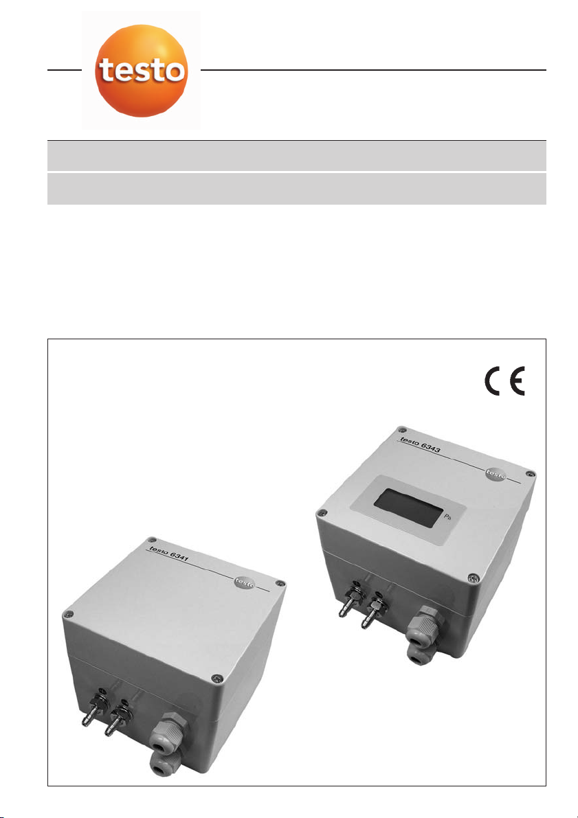
testo 6341 / testo 6343 / testo 6349
Differential pressure transmitters
Bedienungsanleitung de
Instruction manual en
Page 2

2
Foreword/Copyright
Foreword/Copyright
Foreword
Dear Testo customer
We are delighted that you have chosen a product from Testo. We hope that the product
will give you a long period of satisfaction and will aid you in your work.
If problems should occur which you cannot rectify yourself, please consult our service
department or your dealer. We will endeavour to provide fast and competent assistance
to avoid lengthy down times.
Copyright
This documentation is subject to the copyright of testo AG. Reproduction and use contrary to the legitimate interests of Testo AG are prohibited without the prior, written consent of the company.
We reserve the right to modify technical details from the descriptions, specifications and
illustrations contained in this documentation.
testo
AG
Postfach 11 40
79849 Lenzkirch
Germany
Page 3
General Information
General Information
This documentation contains important information about the features and use of the
product. Please read this document through carefully and familiarise yourself with the
operation of the product before putting it to use. Keep this documentation to hand so
that you can refer to it when necessary.
Pictograms
The instrument may be dangerous if operated incorrectly. Particularly important information is highlighted in this Instruction manual by pictograms:
Warnings are indicated by a warning triangle. The corresponding
tes the danger level:
Warning!
tionary measures are not taken.
Caution!
if the specified precautionary measures are not taken.
Read the warning advice carefully and take the specified precautionary
measures in order to avoid danger.
Information about special cases or particularities when handling the instrument are
highlighted by an exclamation mark.
Standards/Approvals
According to the conformity certificate, this product fulfills guidelines in
accordance with 89/336/EEC.
means: Serious physical could be caused if the specified precau-
means: Slight physical injury or damage to equipment could occur
Warning wword
indica-
3
Page 4

4
Contents
Contents
Foreword/Copright ..................................................2
General Information ..................................................3
Contents....................................................................4
1. Basic safety information ............................................5
2. Intended use ............................................................6
3. Product description ..................................................7
4. Initial operation ..........................................................8
4.1 Operating mode of the automatic zero point ..............
adjustment ..............................................................8
4.2 Overload capacity ..................................................8
4.3 Mounting and pneumatic connection ........................8
4.4 Electrical connections and analog outputs ................9
4.5 Adjustment ............................................................11
4.5.1 Start teach mode......................................11
4.5.2 Justage 0% ..............................................12
4.5.3 Justage 100% ..........................................12
4.5.4 Justage 50% ............................................13
4.5.5 Justage 25% ............................................13
4.5.6 Justage 75% ............................................13
4.5.7 Finish ........................................................13
5. Error description ......................................................14
6. Dimensioned drawings ............................................15
7. Technical data..........................................................16
8. Accessories/ Spare parts ........................................17
Page 5
1. Basic safety information
1. Basic safety information
Avoid electrical hazards:
Never take measurements with the instrument and its probes on or near live components unless the instrument is expressly approved for current and voltage measurements.
Protect the instrument:
Never store the unit together with solvents (e.g. acetone).
Preserving product safety/warranty entitlement:
Do not blow into the pressure connections!
Operate the instrument only within the parameters specified in the Technical data.
Handle the instrument appropriately and according to its intended purpose.
Never apply force!
Protect measuring instruments from direct sunlight!
Avoid use in corrosive gases.
Do not seal off inputs (otherwise barometric pressure changes could damage instru-
ments with low measurement ranges).
Temperature data on sensors/probes refer only to the measurement range of the sen-
sors. Do not subject handles and lines to temperatures greater than 70°C if they are
not expressly approved for higher temperatures.
Open the instrument for maintenance and repair purposes only if specifically described in the Instruction Manual.
Maintenance work should only be carried out if described in the Instruction Manual.
Please adhere to the steps described. For safety reasons, please only use spare
parts from Testo.
Any additional work should only be carried out by authorised trained personnel.
Otherwise Testo does not accept responsibility for the functioning of the instrument
following maintenance and for the validity of approvals.
Dispose of carefully:
Once its service life has come to an end, return the instrument to us and we will dispose of it.
5
Page 6

6
2. Intended use
2. Intended use
The testo 6341 / testo 6343 / testo 6349 pressure transmitters are pneumatic electrical transmitters for pressure measurement (positive, negative and differential pressure).
The most important part is a pressure cell with a membrane made of beryllium bronze
which is moved between the two chambers of the pressure cell in accordance with differential pressure. The movement is measured without contact via an inductive displacement transmitter. The instruments do not have any frictional or mechanical wearing
parts.
Page 7

3. Product description
testo 6341:
Differential pressure transmitter 0 to10Pa with
automatic zero point adjustment, without display
Pneu- Cable
matic connections
connections
testo 6343
Differential pressure transmitter 0 to10Pa with
automatic zero point adjustment, with display
3. Product description
7
testo 6349
Based on testo 6341 or testo 6343, but with custom-designed version,
e.g. special measuring range
Page 8

4. Initial operation
8
4.1 Operating mode
4. Initial operation
4.1 Operating mode of automatic zero point adjustment
Once supply voltage has been connected, an automatic zero point adjustment is carried
out three times during the first hour (starting time for the sensor) which is then repeated
approximately every hour. It is not possible to measure during the zeroing phase which
lasts approx. 1 second. The value last measured is frozen and output during this phase.
Automatic zero point adjustment compensates temperature drift and positional errors of
the sensor in addition to the zero point error. A manual zero point adjustment (e. g. via
potentiometer) is neither necessary nor possible.
4.2 Overload capacity
”Blowing into” the pressure connections could result in the maximum values
being exceeded.
Such a “test” should be avoided.
If pressure is applied to one of the inputs which is greater than the maximum limit value
(140% of the measurement range), a solenoid valve separates the process pressure
from the pressure cell so that it remains undamaged. The measurement cell is vented
from both sides. The valves to the process pressure are then reopened or the procedure
repeats itself. The last value measured is output at the signal output.
If idle, the sensor is safe at both inputs up to 200 kPa positive pressure. During operation, it provides positive pressure safety at both inputs of up to 200 times the full scale
value of the measurement range (with 10Pa measurement cells therefore 2000Pa,
i.e. 20mbar), but in measurement cells ≥25mbar: overload maximum 6 bar.
4.3 Mounting and pneumatic connection
The testo 6341, testo 6343 and testo 6349 pressure transmitters are precision measuring instruments and should be
handled with care in spite of their robustness. Avoid mounting
near heat and radiation sources. It is advisable to attach (with
screws) the instruments to a vibration-free wall in a vertical
position (hose connections for pressure and negative
pressure should point downward).
Generally, the higher pressure is connected to the presssure connection . Positive pressure can be measured at
the input of the sensor or negative pressure at the
input where the pressure measurement ranges go from 0 to
the measurement range full scale value.
Page 9

4. Initial operation
4.4 Electric connection and analog outputs
Example: Sensor with measurement range 0 to 10 Pa and output 4 to 20mA
Positive pressure measurement: 0 to +10 Pa at the input: 4 to 20mA at output (stan-
dard)
Negative pressure measurement: 0 to - 10 Pa a
Positive pressure can be measured at the input of the sensor while negative pressure
can be measured at the input where the pressure measurement ranges are 0 to ± of
the measurement range full scale value.
Example: Sensor with measurement range 0 to ±10 Pa and output 4 to 20mA:
-10 Pa at input; 4mA at output
0 Pa at input; 12mA at output
+10 Pa at input; 20mA at output
input: 4 to 20mA at output
t
4.4 Analog outputs
Before the supply voltage is connected it must first be defined, via jumper J5
and rotary switch S1, as to which analog signal is to be used (see below and
diagram on page 10).
20.5...28.5VDC supply voltage is connected to the terminals (11 and 13) in accordance
with the connection diagram in the housing lid.
The output signals are available at the signal terminals (1 to 4):
Signal output Power supply
9
Place holder
Signalausgang
Jumper J5
open
closed
Using a jumper (J5), the voltage output can be configured to 2 to 10V or 0 to 10V or the
current output can be reconfigured from 4 to 20mA to 0 to 20mA (compare above diagram).
Place holder
Versorgung
Page 10

4. Initial operation
10
4.4 Electric connection and analog outputs
Using a jumper (J5), the voltage output can be configured to 2 to 10V or 0 to 10V or the
current output can be reconfigured from 4 to 20mA to 0 to 20mA (compare above diagram).
Using the S1 switch, the time constant of the sensor can be set in accordance with the
following table. The higher the time constant, the more dampened the reaction of the
output signal (floating mean value).
Platzhalter Platine
Jumper J5
Rotary switch S1
Switch Time Output
position constant signal
0 None linear
1 1s inear
2 2.5s linear
3 5s linear
4 10s linear
5 20s linear
6 30s linear
7 40s linear
Switch position 8 - F only relevant for volume flow measurements
in connection with orifice plates, pitot tubes or similar.
Setting will be carried out on request by factory. The following information is necessary:
∧
Max. signal max dP max. velocity / flow
=
Example: 20mA 95mbar 20m
∧
=
∧
=
∧
3
=
/h
Page 11

4. Initial operation
4.5 Adjustment
4.5 Adjustment
A manual zero adjustment (at 0Pa) is generally not necassary, see chapter 4.1. The
automatic zero adjustment makes such handling superfluous.
Thanks to the excellent long-term stability also an adjusment of span (full scale) is usuallly not necassary.
In case the user wants or has to perform the adjustment, and he has a very precise
pressure reference (pressure generator), here is the description of the adjustment procedure:
The display value is driven by the voltage signal, so it makes sense to calibrate the
voltage signal rather than the current signal. Anyhow, this description gives both
values. The current values (range 0..20 mA, no matter how jumper J5 is set) are
given in squared brackets […].
There are three types of dP ranges. Please identify your type (see table) and perform
the corresponding procedure (steps 1, 2 etc.). Grey areas in the table show steps
that are not used for the adjustment (e.g. for ranges type B there is no adjustment
at 25%, 50% or 75% of full scale).
Hint
Ranges of type B can be treated as type C in case 5 instead of 2 adjustment points
shall be used.
11
Range Characteristical Example Adjustment point in percent of full scale
type range (pressure scale)
0% 25% 50% 75% 100%
The following pressure values (in Pa, referring to the examples) have to be supplied
A Ranges 0…xx Pa 0..50 Pa 0 12,5 25 37,5 50
B Ranges +/- xx Pa -100..+100 Pa -100 100
C Asymmetric ranges -10..+60 Pa -10 7,5 25 42,5 60
by the reference pressure generator.
4.5.1 Start teaching mode
Testo 6341 / 6343 gets adjusted in "teaching mode". Please perform as follows:
· Interrupt the power supply of the instrument
· Close Jumper J1, see drawing
· Disconnect pressure connections (dP=0)
Page 12

4. Initial operation
12
4.5 Adjustment
· Supply the instrument again; it is now in "teaching mode"
· An eventual offset is now set to zero
4.5.2 Adjusting 0%:
You will now measure a value of 1,25 VDC between the voltage output connectors
and 2 [respectively 2,5 mA between connectors 3 and 4]. Close Jumper J2 shortly and
open it again (this way it is written into the EEPROM). Now the voltage output (connectors 1 and 2) shows 0 VDC [the current output, connectors 3 and 4, shows 0 mA]. If
it doesn't, you can now adjust the zero signal by turning potentiometer P2 until the voltage output is at 0 VDC [until the current output is at 0 mA].
Now pressurize as follows (using the reference pressure generator):
· For ranges type A: Leave the pressure connections open (dP = 0)
· For ranges type B: Pressurize the pneumatic "minus" with 100% (full scale value, e.g.
100 Pa) supplied by the pressure reference.
· For ranges type C: Supply the minimum pressure range value, e.g. 10 Pa, to the
pneumatic minus (or to pneumatic plus, if the minimum range is > 0 Pa)
· Then (for all types) close jumper J2 shortly and open it again.
4.5.3 Adjusting 100%
Now the voltage output (connectors 1 and 2) shows 10 VDC [20 mA]. If it doesn't, you
can now adjust the span signal by turning potentiometer P3 until the voltage signal reaches exactly 10 VDC [by turning potentiometer P4 until the current signal reaches exactly 20 mA]. Then pressurize the pneumatic "plus" with 100% of full scale. Then close jumper J2 shortly and open it again.
· For ranges type B: Please stop pressurizing the instrument (dP=0 Pa). Please check if
the voltage output now shows 5 VDC [the current output 10 mA] and close jumper
J2 shortly and open it again. Then please check if the voltage output now shows 2,5
VDC [the current output 5 mA] and close jumper J2 shortly and open it again. The
output will now change to 18 VDC [34 mA]. Disconnect jumper J1, switch the instrument off and then on again. Testo 6341/6343 is now ready to use; do not perform
steps 4.5.4, 4.5.5, 4.5.6 and 4.5.7.
Page 13

4. Initial operation
4.5 Adjustment
4.5.4 Adjusting 50% (only types A or C)
Now the voltage output (connectors 1 and 2) shows 5,0 VDC [10 mA]. Now please
pressurize the pneumatic "plus" with 50% of full scale. Then close jumper J2 shortly and
open it again.
4.5.5 Adjusting 25% (only types A or C):
Now the voltage output (connectors 1 and 2) shows 2,5 VDC [5 mA]. Now please pressurize the pneumatic "plus" with 25% of full scale. Then close jumper J2 shortly and
open it again.
4.5.6 Adjusting 75% (only types A or C)
Now the voltage output (connectors 1 and 2) shows 7,5 VDC [15 mA]. Now please
pressurize the pneumatic "plus" with 75% of full scale. Then close jumper J2 shortly and
open it again.
4.5.7 Finish (only types A or C):
Now the voltage output shows 1,25 VDC [2,5 mA]. Now please again pressurize the
pneumatic "plus" with 75% of full scale. Then close jumper J2 shortly and open it again.
The voltage output now goes to 18 VDC [34 mA]. Disconnect jumper J1, switch the
instrument off and then on again. Testo 6341/6343 is now ready to use.
Simplyfied drawing of electronics boards:
13
PlatzhaLTER
Platine1
Jumper J2
Jumper J1
Else please check page 14 for our calibration offers.
Platzhalter Platine2
Potentiometer P2
Potentiometer P3
Potentiometer P1
Potentiometer P4
Supply connector
Signal connector
(see page 9)
Page 14

14
5. Error description
5. Error description
Error description Possible cause Troubleshooting
No output signal Supply voltage not connected Connect correct supply voltage
Incorrect supply voltage connected Connect correct supply voltage
Fuse defective Replace fuse S1 or S2
Input protection diode defective Replace D3 (P6KE30A) at 230VAC, D2 (1N4007) at
Defective Output protection diode defective Replace D7/D8 (PKE18A)
output signal
Cyclical ”clicking” Max. nominal pressure is exceeded, the Connect max. pressure
of valve instrument goes into the positive pressure mode (see type plate)
No display Display plug is inserted incorrectly Turn display plug
Pressure connections were interchanged Connect pressure connections correctly
Pressure measurement cell defective Send instrument to manufacturer for repair
Load too high at current output Adhere to max. load of 500Ω
If we have not answered your question, please contact your local distributor or Testo’s
Customer Service. You will find contact details in the Warranty booklet or in Internet at
www.testo.com.
(see type plate)
24VDC
(watch out for +/-)
Page 15

6. Dimensional drawings
testo 6341 / testo 6349 (on the basis of 6341)
testo 6343/testo 6349 (on the basis of 6343)
6. Dimensioned drawings
15
Page 16

16
7. Technical data
7. Technical data
Feature Values
Measurement ranges 0 to 10Pa to 0 to 100kPa or ±10Pa to ±100kPa (standard testo 6341/6343: 0 to 10Pa)
Output signal 4 to 20mA linear (standard; load R
Medium Air, all non-aggressive gases
Supply voltage 20.5 to 28.5VDC
Measurement inaccuracy 0.35Pa* +0.6% of full scale, measurement inaccuracy of reference is 0.3Pa
Hysteresis 0.1% of full scale value
Overload capacity 200 times (above 25 mbar: 6 bar)
Zero point drift 0, on account of periodic zero adjustment
Drift measurement range
Time constants 1s, 2.5s, 5s, 10s, 20s, 30s, 40s can be switched (rotary switch S1)
Utilisable measurement range -5% to 110% of full scale value (See Fig. 1 and 2)
Working temperature 0°C to 60°C
Storage temperature -10°C to +70°C
Power consumption Approx. 5VA
Protection class IP65 with pressure and electricity lines installed
Connections Electric: 2 PG 9 screw connections, screw terminals ∅2.5mm
Housing in mm (l x b x h): 122 x 120 x 105
Weight Approx. 1500g
EMC acc. to 89/336/EWG
* The measurement inaccuracy of the reference is 0.3Pa
Can also be set: 0 to 10V/2 to 10V, (R
Please note: Measurement cell may be damaged at higher pressures
(0.03% of full scale value) x
Pneumatic: Hose connections ∅6.5mm, for hose with nominal width 4 or 5mm
≤500Ω)
L
0/4 to 20mA; (RL≤500Ω)
| t-22 |
°C
≥ 2Ω)
L
2
Voltage output 0...10V Current output
depending on full scale value. depending on full scale value.
100% = Full scale value of 100% = Full scale value of differential
diff. pressure meas. range pressure measurement range
Fig. 1 Fig. 2
Page 17

8. Accessories
8. Accessories
Name Part no.
dP transmitter 0 to 10Pa, automatic zeroing, without display 0555 6341
dP transmitter 0 to 50Pa, without display 0555 6342
dP transmitter 0 to10Pa, automatic zeroing, with display 0555 6343
dP transmitter 0to 50Pa, with display 0555 6344
ISO calibration with 5 points (0-25-50-75-100-0 (all points in % of full scale value)) 0520 0005
ISO calibration at freely selectable points 0520 0105
Silicone hose, 5m long, 4mm inner diameter, 1.5mm wall thickness 0554 0440
External display testo 54-2AC, 2 relay outputs (to 300VAC, 3A), 230VAC 5400 7553
Power unit (DIN rail mounting) 90 to 264VAC / 24VDC (3A) 0554 1749
17
Page 18

testo AG
Postfach 11 40, 79849 Lenzkirch
Testo-Straße 1, 79853 Lenzkirch
Telefon: (07653) 681-0
Fax: (07653) 681-100
E-Mail: info@testo.de
Internet: http://www.testo.com
0973.6341/05/HW/wh/17.10.2005
 Loading...