

Page 1
testo AG · Testo-Strasse 1 · D-79853 Lenzkirch · www.testo.com
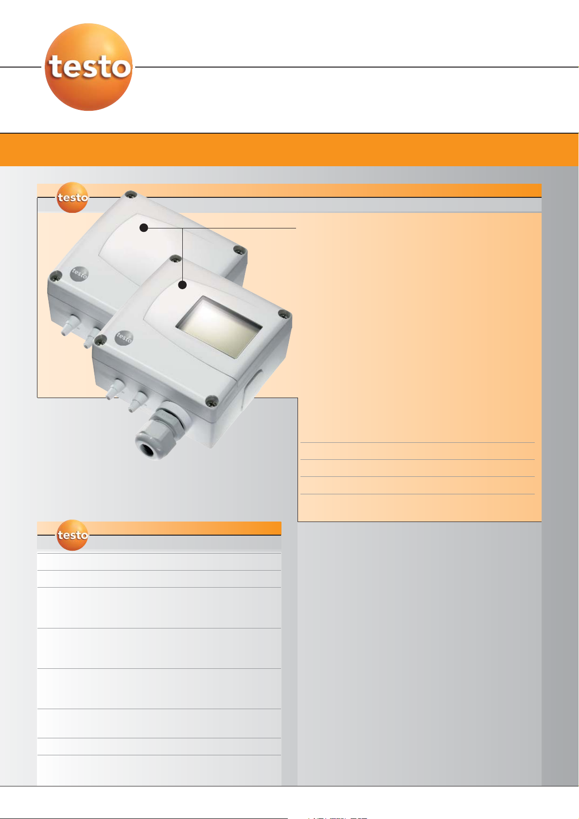
Wall version with
display
Wall version
without display
testo 6321
Committing to the future
Differential pressure transmitter
A differential pressure transmitter with a good
price/performance ratio for applications in air
conditioning and ventilation technology. The automated
building services must always be monitored precisely,
whereby the requirements placed on the measuring
technology are increased. testo 6321 fulfills these
requirements by ensuring the best possible system
function, optimization of the climatic conditions and
energy savings by means of highly accurate
measurement, stable over the long-term, of the
differential pressure.
Areas of application
• Industrial and commercial buildings, e.g. in
production and storage
• Offices and administrational buildings
• Sales areas and exhibition halls
• Museums and libraries
• School buildings, hotels, clinics etc.
DS 6321 EN/msp/A/12.02.2010 Status 12th Feb. 2010 Subject to change without notice.
• Measurement of differential pressure in the
measuring range of 100 Pa to 2 bar
• Magnetic valve for automatic zero-point adjustment
guarantees high temperature-independent accuracy
and long-term stability
• Accuracy ±1.2 % of measuring range + intrinsic error
of 0.3 Pa – valid for zeroing cycle of 60 sec/nominal
temperature +22 °C
• P2A software for parameterization, adjustment and
analysis, saves time and costs in commissioning and
maintenance
• Freely scalable: ±50% of measuring range final value
and free scalability within the measuring range
• Diverse analog outputs and measuring ranges
• Display optional
SPECIFICATIONS
testo 6321
SPECIFICATIONS
testo 6321
Page 1/4
Page 2

Subject to change without notice.
testo AG · Testo-Strasse 1 · D-79853 Lenzkirch · www.testo.com
Supply
Display
Differential pressure
Analog outputs
Further outputs
Housing
Miscellaneous
Display 1-line LCD (optional)
testo 6321
Differential pressure transmitter
Technical data
Measurement parameters
DS 6321 EN/msp/A/12.02.2010 Status 12th Feb. 2010
Measuring range 0 to 100 Pa
0 to 10 hPa
0 to 20 hPa
0 to 50 hPa
0 to 100 hPa
0 to 500 hPa
0 to 1000 hPa
0 to 2000 hPa
-100 to 100 Pa
-10 to 10 hPa
-20 to 20 hPa
-50 to 50 hPa
-100 to 100 hPa
-500 to 500 hPa
-1000 to 1000 hPa
-2000 to 2000 hPa
Measurement uncertainty* ±1.2% of measuring range final value
±0,3 Pa
Temperature gain drift: 0.05% of
measuring range per Kelvin deviation
from nominal temperature 22 °C
Zero-point drift: 0%
(due to zero-point adjustment)
Measuring rate 1/s
Resolution 12 bit
Accuracy of the analog
outputs
0 to 1 V ±2,5 mV
0 to 5 V ±12,5 mV
0 to 10 V ±25 mV
4 to 20 mA ±0,05 mA
Max. load 500 Ω
Overload capacity Measuring range Overload
0 to 100 Pa 20000 Pa
0 to 10 hPa 200 hPa
0 to 20 hPa 200 hPa
0 to 50 hPa 750 hPa
0 to 100 hPa 750 hPa
0 to 500 hPa 2500 hPa
0 to 1000 hPa 2500 hPa
0 to 2000 hPa 2500 hPa
-100 to 100 Pa 20000 Pa
-10 to 10 hPa 200 hPa
-20 to 20 hPa 200 hPa
-50 to 50 hPa 750 hPa
-100 to 100 hPa 750 hPa
-500 to 500 hPa 2500 hPa
-1000 to 1000 hPa 2500 hPa
-2000 to 2000 hPa 2500 hPa
Inputs and outputs
Output type 0 to 1/5/10 V (4-wire)
4 to 20 mA (4-wire)
other analog outputs Minin DIN for P2A software (adjustment
and parameterization software)
Voltage supply 20 to 30 V AC/DC
Current consumption 30 mA
General
Material / colour ABS / white (RAL 9010) or light grey
Weight Approx. 160 g
Resolution Measuring range Resolution
0 to 100 Pa 0.1 Pa
0 to 10 hPa 0.01 hPa
0 to 20 hPa 0.01 hPa
0 to 50 hPa 0.01 hPa
0 to 100 hPa 0.1 hPa
0 to 500 hPa 0.1 hPa
0 to 1000hPa 1 hPa
0 to 2000hPa 1 hPa
-100 to 100 Pa 0.1 Pa
-10 to 10 hPa 0.01 hPa
-20 to 20 hPa 0.01 hPa
-50 to 50 hPa 0.01 hPa
-100 to 100 hPa 0.1 hPa
-500 to 500 hPa 0.1 hPa
-1000 to 1000 hPa 1 hPa
-2000 to 2000 hPa 1 hPa
Humidity (sensor) 0 to 90 %rF
Temperature (sensor) -5 to +50 °C
Storage temperature -40 to +80 °C
* Measurement inaccuracy according to GUM: ±1.2% of measuring range final value ±0.3 Pa
GUM (Guide to the Expression of Uncertainty in Measurement):
ISO guideline for the determination of measurement uncertainty, in order to make measurement
results comparable worldwide.
The following variables are taken into account in determining uncertainty:
- Hysteresis - Long-term stability
- Linearity - Adjustment site/works calibration
- Reproduceability - Test site
Protection class IP65
only when the transmitter is wired
and/or sealing plugs are in use
EMC EC guideline: 2004/108/EC
Automatic zero-point
adjustment
Every 60 seconds ex-works
Operating conditions
Page 2/4
Sensor Piezoresistive sensor
Autom. zero-point adjustment via magnetic valve
Page 3

testo AG · Testo-Strasse 1 · D-79853 Lenzkirch · www.testo.com
Subject to change without notice.
4-wire wiring 3-wire wiring
testo 6321
Differential pressure transmitter
Technical drawings
DS 6321 EN/msp/A/12.02.2010 Status 12th Feb. 2010
Connection plan
Page 3/4
-
+
U
2
1
+
dP
-
34
+
U
1
dP
2
-
+
3
4
Page 4

testo AG · Testo-Strasse 1 · D-79853 Lenzkirch · www.testo.com
Subject to change without notice.
Differential pressure transmitter
Status 12th Feb. 2010DS 6321 EN/msp/A/12.02.2010
testo 6321
The following options can be specified for the testo 6321
AXX Measuring range
BXX Analog output/supply
CXX Display
EXX Housing colour
FXX Unit
KXX Language of the instruction manual (for
bilingual paper instruction manual)
AXX Measuring range
A03 0 to 100 Pa
A05 0 to 10 hPa
A06 0 to 20 hPa
A07 0 to 50 hPa
A08 0 to 100 hPa
A09 0 to 500 hPa
A10 0 to 1000 hPa
A11 0 to 2000 hPa
A23 -100 to 100 Pa
A25 -10 to 10 hPa
A26 -20 to 20 hPa
A27 -50 to 50 hPa
A28 -100 to 100 hPa
A29 -500 to 500 hPa
A30 -1000 to 1000 hPa
A31 -2000 to 2000 hPa
BXX Analog output / supply
B02 0 to 1 V (4-wire, 24 VAC/DC)
B03 0 to 5 V (4-wire, 24 VAC/DC)
B04 0 to 10 V (4-wire, 24 VAC/DC)
B06 4 to 20 mA (4-wire, 24 VAC/DC)
CXX Display
C00 without display
C01 with display
EXX Housing colour
E01 Housing colour light grey, incl. Testo logo
(coloured)
E02 Neutral housing, white, without Testo logo
E03 Neutral housing, white, incl. Testo logo
(black/white)
FXX Unit
F01 Pa / min / max
F02 hPa / min / max
F03 kPa / min / max
F04 mbar / min / max
F05 bar / min / max
F06 mm H
2
O / min / max
F07 inch H
2
O / min / max
F08 inch HG / min / max
F09 kg/cm
²
/ min / max
F10 PSI / min / max
KXX Instruction manual language
K01 Instruction manual German-English
K02 Instruction manual French-English
K03 Instruction manual Spanish-English
K04 Instruction manual Italian-English
K05 Instruction manual Dutch-English
K06 Instruction manual Japanese-English
K07 Instruction manual Chinese-English
Order code for testo 6321 transmitter with
the following options:
- Measuring range 0 to 100 Pa
- Analog output 0 to 5 V
- Without display
- Housing colour light grey
- Unit mbar
- Language of instruction manual
German/English
Example:
0555 6321 A03 B03 C00 E00 F04 K01
Deliver incl. wall hoder
Page 4/4
Page 5

Page 6

 Loading...