

Page 1
testo 570 · Digital manifold
Instruction manual
Page 2

2
Page 3

1 Contents
1 Contents
1 Contents ................................................................................................... 3
2 Safety and the environment .................................................................... 4
2.1. About this document ........................................................................ 4
2.2. Ensure safety ................................................................................... 5
2.3. Protecting the environment .............................................................. 5
3 Specifications .......................................................................................... 6
3.1. Use .................................................................................................. 6
3.2. Technical data ................................................................................. 6
4 Product description ................................................................................. 9
4.1. Overview.......................................................................................... 9
5 First steps .............................................................................................. 11
6 Using the product .................................................................................. 15
6.1. Preparing for measurement ........................................................... 15
6.1.1. Connecting temperature probe, Testo 552 and accessories .......................... 15
6.1.2. Switching the instrument on ........................................................................... 17
6.1.3. Choosing the measuring mode ...................................................................... 18
6.2. Performing the measurement ........................................................ 19
6.2.1. Measuring ...................................................................................................... 19
6.2.2. Tightness test / pressure drop test ................................................................. 20
6.2.3. Evacuation / vacuum display .......................................................................... 21
6.2.4. Vacuum measurement ................................................................................... 21
6.2.5. Charging ........................................................................................................ 22
6.2.6. Emptying ........................................................................................................ 22
6.2.7. Pressure/Compressor .................................................................................... 23
6.2.8. Current ........................................................................................................... 23
6.2.9. Efficiency calculation ...................................................................................... 23
6.3. Saving measurement values ......................................................... 23
6.4. Printing measurement values ........................................................ 25
7 Maintaining the product ........................................................................ 26
8 Tips and assistance ............................................................................... 28
8.1. Questions and answers ................................................................. 28
8.2. Measurement parameters ............................................................. 28
8.3. Error reports .................................................................................. 29
8.4. Accessories and spare parts ......................................................... 29
9 Appendix ................................................................................................ 30
9.1. Basis of calculation COP ............................................................... 30
3
Page 4
2 Safety and the environment
2 Safety and the environment
2.1. About this document
Use
> Please read this documentation through carefully and
familiarize yourself with the product before putting it to use. Pay
particular attention to the safety instructions and warning advice
in order to prevent injuries and damage to the products.
> Keep this document to hand so that you can refer to it when
necessary.
> Hand this documentation on to any subsequent users of the
product.
Symbols and writing standards
Representation Explanation
Warning advice, risk level according to the
signal word:
Warning! Serious physical injury may occur.
Caution! Slight physical injury or damage to
the equipment may occur.
> Implement the specified precautionary
measures.
Note: Basic or further information.
1. ...
2. ...
Action: more steps, the sequence must be
followed.
> ... Action: a step or an optional step.
- ... Result of an action.
Menu Elements of the instrument, the instrument
display or the program interface.
[OK] Control keys of the instrument or buttons of
the program interface.
... | ... Functions/paths within a menu.
“...” Example entries
4
Page 5

2.2. Ensure safety
> Do not operate the instrument if there are signs of damage at
the housing, mains unit or feed lines.
> Do not perform contact measurements on non-insulated, live
parts.
> Do not store the product together with solvents. Do not use any
desiccants.
> Carry out only the maintenance and repair work on this
instrument that is described in the documentation. Follow the
prescribed steps exactly. Use only original spare parts from
Testo.
> The objects to be measured or the measurement environment
may also pose risks: Note the safety regulations valid in your
area when performing the measurements.
> If the measuring instrument falls or another comparable
mechanical load occurs, the pipe sections of the refrigerant
hoses may break. The valve positioners may also be damaged,
whereby further damage to the interior of the measuring
instrument may occur that cannot be identified from the outside.
The refrigerant hoses must therefore be replaced with new,
undamaged refrigerant hoses every time the measuring
instrument falls or following any other comparable mechanical
load. Send the measuring instrument to Testo Customer
Service for a technical check for your own safety.
> Electrostatic charging can destroy the instrument. For online
measurement (instrument connected to PC/laptop) or when
using the mains unit in particular, you should therefore integrate
all components (system, valve manifold of the manifold gauge,
refrigerant bottle, etc.) into the equipotential bonding (earthing
system) prior to measurement. Please see the safety
instructions for the system and the refrigerant used.
2 Safety and the environment
2.3. Protecting the environment
> Dispose of faulty rechargeable batteries/spent batteries in
accordance with the valid legal specifications.
> At the end of its useful life, send the product to the separate
collection for electric and electronic devices (observe local
regulations) or return the product to Testo for disposal.
> Refrigerant gases can harm the environment. Please note the
applicable environmental regulations.
5
Page 6

3 Specifications
3 Specifications
3.1. Use
The testo 570 is a digital manifold for commissioning, maintenance
and service work on refrigeration systems and heat pumps. It can
be used for fault diagnose and online measurements on
refrigeration systems and heat pumps. The testo 570 is only to be
used by qualified expert personnel.
With its functions the testo 570 replaces mechanical manifolds,
thermometers and pressure/temperature charts. Pressures and
temperatures can be applied, adapted, tested and monitored.
Its scope of functions can be considerably extended by means of
extensive, separately available accessories, e.g. various
temperature sensors, clamp probe, oil pressure probe,
PC software.
The testo 570 is compatible with most of the non-corrosive
refrigerants, water and glycol. The testo 570 is not compatible with
ammoniac refrigerants.
3.2. Technical data
Then product must not be used in explosive environments!
Feature Values
Measurement
parameters
Pressure: kPa/MPa/bar/psi
Temperature: °C / °F / K
Vacuum: hPa / mbar/ Torr / inH
inHg / Pa
Current: A
Measuring sensor
Pressure: 2 x pressure sensor
Temperature: 3 x NTC
Measuring cycle 0.75 s
Connections
Pressure connections: 3 x 7/16" UNF+ 1x
5/8“
NTC measurement
Interfaces 3x Mini-DIN, 1x Mini-USB, 1 x IR
O / Micron /
2
1
1
via clamp probe (optional accessory)
6
Page 7

3 Specifications
Feature Values
Measurement
ranges
Pressure measurement range
HP/LP: -100…5000 kPa / -0.1…5 Mpa
/ -1…50 bar (rel) / -14.7…725 psi
Temperature measurement
range: -50…+150 °C / -58…302 °F
Measurement range vacuum (rel): -1…0 bar
/ -14.7…0 psi
Overload 52 bar, 5200 kPa, 5.2 Mpa, 754 psi
Resolution
Resolution pressure: 0.01 bar / 0.1 psi /
1 kPa / 0.001 Mpa
Resolution temperature: 0.1 °C / 0.1 °F /
0.1 K
Vacuum resolution: 1 hPa / 1 mbar / 0.5 Torr
Accuracy (nominal
temperature
22 °C/71.6°F)
/ 0.5 inH
Pressure: ±0.5% of final value (±1 digit)
Temperature (-40…302 °F/-40…+150 °C):
±0.5 °C (±1 Digit), ±0.9 °F (±1 digit), ±0.5 K
O / 0.02 inHg / 500 Micron / 100 Pa
2
(±1 digit)
Vacuum: 1% of final value (±1 digit)
No. of refrigerants 40
Selectable
refrigerants
No refrigerant, R12, R22, R123, R134a,
R227, R290, R401A, R401B, R402A, R402B,
R404A, R406A, R407A, R407C, R408A,
R409A, R410A, R411A, R413A, R414B,
R416A, R417A, R420A, R421A, R421B,
R422A, R422B, R422D, R424A, R427A,
R434A, R437A, R438A, R502, R503, R507,
R600, R600a, R744 (only in the permissible
measurement range up to 50 bar), R1234yf
Further refrigerants can be
downloaded under www.testo.com.
Memory capacity
10000 single measurements or 50 series
measurements (each with a measuring cycle
of 2 s, measurement period 100 h)
Measuring cycle 2 s...24 h (freely selectable)
Measurable media
Measurable media: all media that are stored
in the testo 570. Not measurable: ammonia
(R717) and other refrigerants which contain
ammonia
7
Page 8

3 Specifications
Feature Values
Ambient conditions
Housing Material: ABS / PA / TPE
IP-class 42 (position in use hanging down)
Power supply
Display Type: Illuminated LCD
Directives,
standards and tests
Warranty Duration: 2 years
Operating temperature: -20 to 50 °C / -4 to
122°F
Storage temperature: -20...60 °C / -4...140 °F
Humidity in area of use: 10 ... 90 %RH
Dimensions approx. 280 x 135 x 75 mm
Weight: approx. 1200 g (without batteries)
Current source: 4 x 1.5 V rechargeable/nonrechargeable batteries
Type AA / Mignon / LR6
Battery life: > 40h (display light off)
Response time: 0.5 s
EC Directive: 2004/108/EC
Terms of warranty: see website
www.testo.com/warranty
8
Page 9
4 Product description
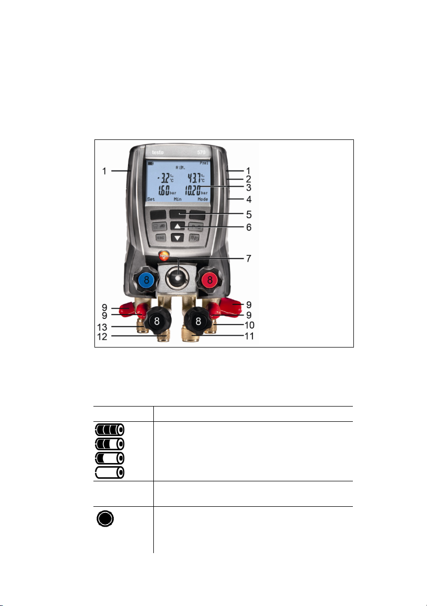
4.1. Overview
Display and control elements
4 Product description
1 Sensor socket Mini-DIN for NTC-temperature sensor, with
socket cover.
2 Suspension attachment, foldable (backside).
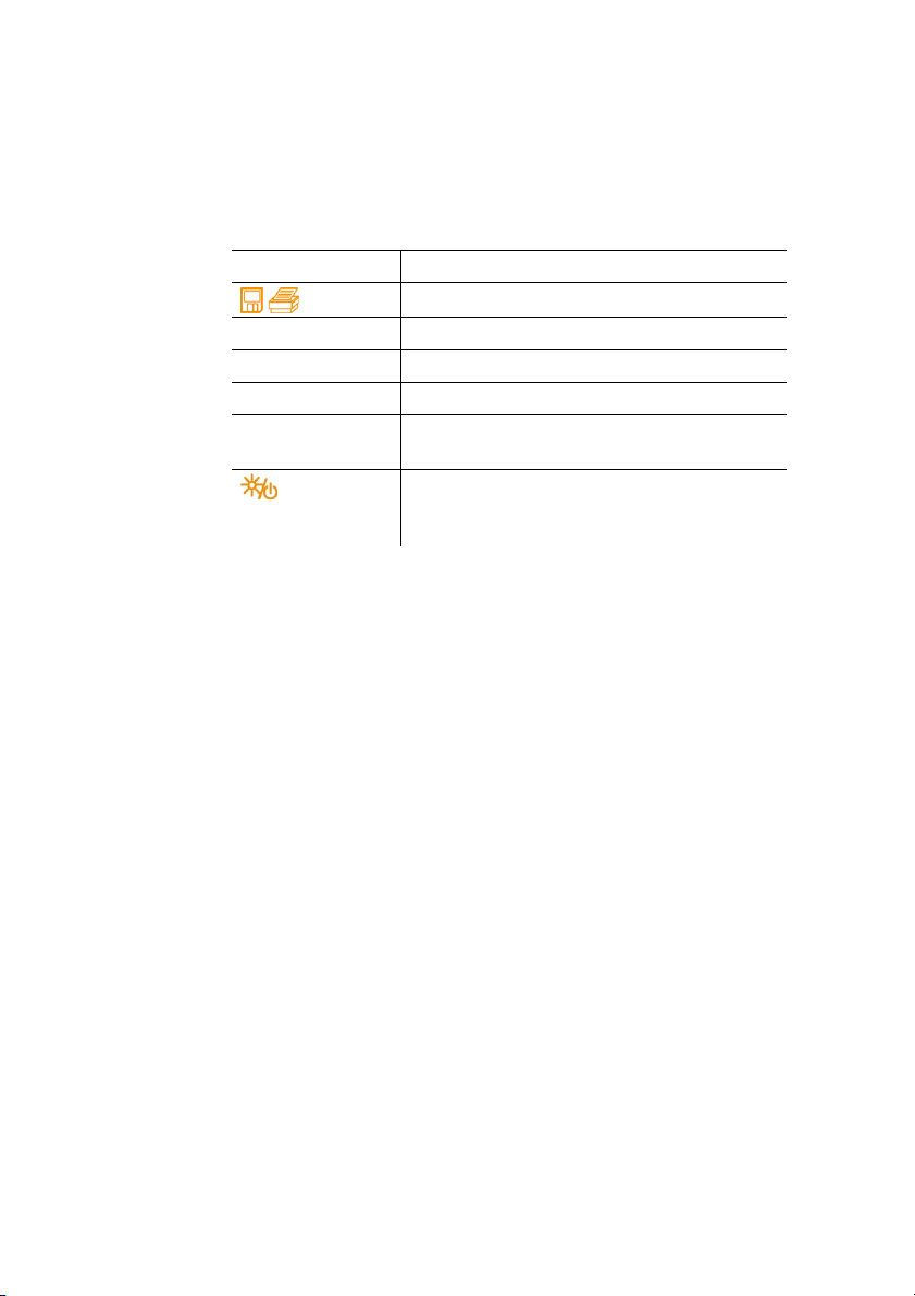
3 Display Instrument status icons:
Icon Meaning
no battery
Battery capacity: >75% / >50% / >25% / <10%
Instrument is operated with power supply unit.
indication
The measurement value is saved; in case of a
single measurement the inner circle flashes
once, with serial measurements the circle
flashes with each save procedure.
9
Page 10
4 Product description
4 Battery compartment. Charging rechargeable batteries inside
5 Multi-function keys: The relevant function appears in the
6 Control keys:
Key Function
[ ]
[ESC]
[▲]
[▼]
[p=0] Zero the pressure sensor in the range +1 to
[]
7 Inspection glass for refrigerant flow.
8 4 x valve actuators.
9 4 x hose brackets for refrigerant hoses.
10 Connection 7/16“ UNF, brass.
11 Connection 5/8“ UNF, brass, for vacuum pump.
12 Connection 7/16“ UNF, brass, for e.g. refrigerant cylinders, with
13 Connection 7/16“ UNF, brass.
the instrument is not possible!
display.
Save or print measurement data.
Exit the menu option.
Up-key: Change display view.
Down-key: Change display view.
-1.3 bar.
Switch instrument on / off; short actuation
during operation: switches illumination on /
off.
High pressure, for refrigerant hoses with quick release screw
fitting, passage for valve actuator lockable.
screw cap.
Low pressure for refrigerant hoses with quick release screw
fitting, passage for valve actuator lockable.
10
Page 11
5 First steps
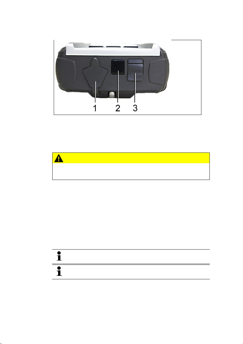
Interfaces
1 Mini-DIN connection for optional temperature sensors, testo 552
and accessories
2 IR-interface for testo protocol printer
3 Mini-USB connection for power supply unit and connection to
PC
CAUTION
Risk of injury from infrared beam!
> Do not direct infrared beam at human eyes!
5 First steps
Inserting batteries/rechargeable batteries
1. Unfold the suspension attachment and open the battery
compartment (clip lock).
2. Insert the batteries (scope of delivery) or rechargeable batteries
(4 x 1.5 V, type AA / NiMH / AA) into the battery compartment.
Observe the polarity!
3. Close the battery compartment.
When not in use for long period: Take out the batteries /
rechargeable batteries.
Recharge the rechargeable batteries completely before
using the instrument.
11
Page 12

5 First steps
Switching the instrument on
> Press [].
- Initializing phase:
• All display segments light up (duration: 2s).
- Measurement view is opened.
The first time the instrument is switched on after a battery has been
inserted or replaced, the following factory settings are stored:
• Language: English UK
• Date: 01/01/2011
• Time: 12:00
• Temperature unit: °C
• Pressure unit: bar
• Vacuum unit: mbar
• Pressure mode: prel
• Weight unit: kg
• Refrigerant: R12
To change the default settings:
See Making settings, page 13.
12
Display
1 Selected pressure mode
2 Condensation temperature/ acc. to temperature sensor right /
subcooling / differential temperature sensor left&right. The
display reading of measurement values varies in dependence
on the set mode
See also Performing the measurement, page 19.
3 [Min/Max/Mean/Normal] (exemplary for pressure/temperature
mode): The middle multi-function key can be used to display the
minimum, maximum and mean values.
4 [Mode] selectable via the right multi-function key
See also Performing the measurement, page 19.
Page 13

5 First steps
5 [Set] selectable via the left multi-function key
6 Evaporation temperature / acc. to temperature sensor A /
superheating
7 Chosen refrigerant
8 Battery status indication/rech. batt. charge indication
Making settings
1. Press [Set].
- The configuration menu is opened.
2. Select function and set parameters:
Key functions
Representation Explanation
[▲] or [▼]
[Ok]
[ESC]
Choose function/setting
Activate function or confirm parameter/setting
Exit the configuration menu
Adjustable parameters
Refrigerant: Select the refrigerant from the list:
Representation Explanation
R... Refrigerant number of refrigerant acc. to
ISO 817
T... Special Testo designation for certain
refrigerants
---
no refrigerant selected.
With the software testo Easy Kool you can feed additional
refrigerants into the instrument, see separate operating
instructions.
Efficiency calc.: Select the procedure (COP heat pump) and enter
the required parameters (may vary in dependence on selected
procedure). The inputs have an effect on the measuring mode
efficiency calc.
See also Performing the measurement, page 19.
See also Basis of calculation COP, page 30.
Temperature unit: Select the desired unit.
Pressure unit: Select the desired unit.
Vacuum unit: Set pressure unit for vacuum.
Pressure mode: Depending on the chosen unit for pressure:
Change between absolute and relative pressure displays.
13
Page 14

5 First steps
Vacuum pressure mode: Select the pressure mode for the
evacuation mode.
See also Performing the measurement, page 19.
Weight unit: Select the desired unit from the list.
Measuring mode: Select normal mode, combi mode
Display Mode Function
none Normal mode
Normal function of the digital
manifold
Auto
Combi mode
When combi mode is
activated the digital manifold
testo 570 automatically
reverses the display of high
and low pressure. This
automatic reversal occurs
when the pressure in the low
pressure side is 1 bar higher
than the pressure in the high
pressure side. This switching
over is indicated by ---flashing in the display. This
mode is particularly suitable
for air conditioning systems
that provide cooling and
heating.
Date/Time: Adjust the flashing number with [▲] and [▼] and press
[◄]
and [►] to go to the next numerical block. Confirm the input
with [OK].
Language (This setting influences the date format): Select the
language from the list and press [OK] to confirm.
Probe type: Select the desired probe type from the list.
Device info: Show serial number and firmware version.
14
Operating the valve actuators
With respect to the refrigerant flow path the digital manifold
behaves just like a conventional four-way manifold. The passages
are opened by opening the valves. The applied pressure is
measured with the valves closed and the valves opened.
> Open valve: Turn valve actuator anticlockwise.
> Close valve: Turn valve actuator clockwise.
Page 15

6 Using the product
WARNING
Tighten the valve actuator only hand-tight. Do not use any tools for
tightening, this could damage the thread.
WARNING
Valve positioner tightened too tightly.
• Damage to the PTFE seal (1).
• Mechanical deformation of the valve piston (2) leading to the
PTFE seal (1) falling out.
• Damage to the thread of the threaded spindle (3) and the valve
screw (4).
• Broken valve knob (5).
Tighten the valve positioner only hand-tight. Do not use any tools
to tighten the valve positioner.
6 Using the product
6.1. Preparing for measurement
6.1.1. Connecting temperature probe, Testo 552 and
15
accessories
Sensors must be connected before the measuring
instrument is switched on, so that they are recognised by
the instrument.
Page 16

6 Using the product
Surface temperature sensor
An NTC temperature sensor (accessory) must be connected for
measuring the pipe temperature and for automatic calculation of
superheating and subcooling.
Deactivating the surface compensation factor for immersion
and air temperature probe
A surface compensation factor has been set in the measuring
instrument to reduce the measuring errors in the main field of
applications. This reduces measuring errors when using surface
temperature probes.
If the measuring instrument testo 570 is used in combination with
insertion or air temperature probes (accessories), this factor must
be deactivated:
1. Press [Set].
2. Select the Probe type.
3. Select Immersion probe.
4. Press [Esc].
- The surface compensation factor has been deactivated in the
• In combination with the testo 570, the testo 552 can be
used as an external high-precision vacuum probe, if
connected to the front of the testo 570 using the
connection cable 0554 5520. The firmware version 1.09
or later must be installed for this.
• Before connecting both devices, the testo 552 must be
switched on.
• The testo 570 will only connect to the testo 552 once
Evacuation mode has been activated.
• The required pressure unit display must be set in the
testo 570.
• In order to be able to use the readings from the testo
552 via the testo 570 in the EasyKool software, you
need EasyKool software version 4.0 or later.
• (See testo 552 instruction manual.)
device.
For measurements with a surface temperature probe the
probe type must be reset to surface probe.
Each time the device is switched on the surface
compensation factor is activated again as standard.
16
Page 17

6 Using the product
Accessories
Clamp probe and oil pressure probe can only plugged to
connection (1).
Position the accessory as appropriate for the measurement task:
Measurement task
Position
(measurement channel)
Superheating
At the end of the evaporator / inlet of
compressor
Subcooling
At the end of the condenser / inlet of
expansion valve
Differential temperature On the measurement object
Current measurement On the electrical consumers
Charging/emptying On the system
Oil lubrication of the
compressor
On compressor oil measurement
fitting
6.1.2. Switching the instrument on
> Press [].
Zeroing the pressure sensors
Zero the pressure sensors before every measurement.
✓ All connections must be pressureless (ambient pressure).
> Press [P=0] to execute zeroing.
Connecting the refrigerant hoses
Before each measurement check whether the refrigerant
hoses are in flawless condition.
17
Page 18

6 Using the product
✓ The valve actuators are closed.
1. Connect the refrigerant hoses for low-pressure side (blue) and
high-pressure side (red) to the measuring instrument.
2. Connect the refrigerant hoses to the system.
WARNING
The measuring instrument dropping down or any other comparable
mechanical load can cause breakage of the pipe pieces in the
refrigerant hoses. The valve actuators may also suffer damage,
which in turn could result in further damage inside the measuring
instrument, which may not be detectable from outside.
> For your own safety you should return the measuring
instrument to the Testo Service for technical inspection.
> You should therefore always replace the refrigerant hoses with
new ones after the measuring instrument has dropped down or
after any comparable mechanical loading.
6.1.3. Choosing the measuring mode
1. Press [Mode].
- The configuration menu is opened.
2. Choose the measuring mode.
Key functions
Representation Explanation
[▲] or [▼]
[Ok]
[ESC]
Select measuring mode
Enable measuring mode
Exit the menu
Selectable functions
• Pressure/Temperature
• Tightness test
• Evacuation
• Charging
• Emptying
• Pressure/Compressor
• Current
• Efficiency calc.
See also Performing the measurement, page 19.
18
Page 19

6 Using the product
6.2. Performing the measurement
WARNING
Risk of injury caused by pressurized, hot, cold or toxic
refrigerants!
> Wear protective goggles and safety gloves.
> Before applying pressure to the measuring instrument: Always
fasten the measuring instrument on the suspension attachment
to prevent it from falling down (danger of breakage)
> Before each measurement check the refrigerant hoses for
flawless condition and correct connection. Do not use any tools
to connect the hoses, tighten hoses only hand-tight (max.
torque 5.0 Nm / 3.7ft*lb).
> Comply with the permissible measuring range (-1…50 bar).
Pay particular attention in systems with refrigerant R744, since
these are frequently operated with higher pressures.
6.2.1. Measuring
✓ The actions described in the chapter “Preparing for
measurement” have been performed.
The mode Pressure/Temperature is set as standard when
starting the device.
1. Apply pressure to the measuring instrument.
2. Read the measurement values.
With zeotropic refrigerants, the evaporation temperature
to/Ev is displayed after the complete evaporation / the
condensation temperature tc/Co is displayed after complete
condensation.
The measured temperature must be assigned to the
superheating or subcooling side (toh <--> tcu). Dependent on
this assignment, the display will show t
or t
/T2 resp. ∆tcu/SC, depending on the selected display.
cu
- Reading and display illumination are flashing.
• 1 bar before the critical pressure of the refrigerant is
reached,
• when the max. permissible pressure of 49 bar is acceded.
/T1 resp. ∆toh/SH
oh
19
Page 20

6 Using the product
Key functions
> [▲]
Possible display combinations:
Evaporation pressure
Refrigerant evaporation
temperature to/Ev
or (only with inserted temperature sensor)
Evaporation pressure
Measured temperature t
or (only with inserted temperature sensor)
Evaporation pressure
Superheating ∆t
or (only with third inserted temperature sensor T3)
or (only with plugged on clamp probe)
Evaporation pressure
or [▼]: Change the readings display.
Condensation pressure
Refrigerant condensation
temperature tc/Co
Condensation pressure
/T1
Measured temperature tcu/T2
oh
Condensation pressure
/SH
oh
Subcooling ∆tcu/SC
Condensation pressure
Measured temperature T3/T3
Condensation pressure
Measured current value
or (only with inserted oil pressure probe)
Evaporation pressure
Condensation pressure
Measured oil pressure P
With two inserted NTC sensors (T1/T2) ∆t is additionally displayed.
> [Min/Max/Mean/Normal]: Show Min. / Max. measurement
values, mean values (since switching on).
6.2.2. Tightness test / pressure drop test
The temperature compensated tightness test can be used
to check the leak tightness of systems. For this purpose
both the system pressure and the ambient temperature are
measured over a defined period of time. For this purpose a
temperature sensor to measure the ambient temperature
may be connected (recommendation: Deactivate the
surface compensation factor and use NTC air sensors Art.No. 0613 1712).
See also Deactivating the surface compensation factor for
immersion and air temperature probe, page 16.
This provides information about the temperature
20
ext
Page 21

compensated differential pressure and about the
temperature at the beginning/end of the test as a result. If
no temperature sensor is connected, you may also perform
the tightness test without temperature compensation.
✓ The actions described in the chapter “Preparing for
measurement” have been performed.
1. Press [Mode].
2. Select [Tightness test].
- The tightness test view is opened. ∆P is displayed.
3. Start the tightness test: Press [Start].
4. End the tightness test: Press [Stop].
- The result is displayed.
6.2.3. Evacuation / vacuum display
The measurement takes place in the low pressure side.
✓ The actions described in the chapter “Preparing for
measurement” have been performed.
✓ The vacuum pump is connected to the 5/8’’ connection on the
valve block.
1. Press [Mode].
2. Select [Evacuation].
- The evacuation view is opened. The current pressure and the
evaporation temperature of water (H2O) is displayed.
6 Using the product
6.2.4. Vacuum measurement
In order to achieve optimal measuring accuracy in vacuum
measurement, the measuring instrument must be zeroed at
21
ambient pressure.
Zeroing at ambient pressure must be performed for each
vacuum measurement.
• In combination with the testo 570, the testo 552 can be
used as an external high-precision vacuum probe, if
connected to the front of the testo 570 using the
connection cable 0554 5520. The firmware version
1.09 or later must be installed for this.
• Before connecting both devices, the testo 552 must be
switched on.
• The testo 570 will only connect to the testo 552 once
Page 22

6 Using the product
• The required pressure unit display must be set in the
• In order to be able to use the readings from the testo
• (See testo 552 instruction manual.)
✓ The actions described in the chapter “Preparing for
measurement” have been performed.
✓ The desired units have been set.
See Making settings, page 13.
1. Press [].
2. Zero the measuring instrument at ambient pressure [p=0].
3. Press [Mode].
4. Select [Evacuation].
- The evacuation view is displayed.
5. Start evacuation of the system.
6.2.5. Charging
✓ The actions described in the chapter “Preparing for
measurement” have been performed.
1. Press [Mode].
2. Select [Charging].
- The charging view is opened.
3. Enter the value read on the refrigerant scales: Press [Change].
4. Adjust the flashing number with [▲]
and [►] to go to the next number.
5. Confirm the input with [OK].
6. Choose the memory location.
7. Press [Save].
Evacuation mode has been activated.
testo 570.
552 via the testo 570 in the EasyKool software, you
need EasyKool software version 4.0 or later.
and [▼] and press [◄]
6.2.6. Emptying
✓ The actions described in the chapter “Preparing for
measurement” have been performed.
1. Press [Mode].
2. Select [Emptying].
- The emptying view is opened.
3. Enter the value read on the refrigerant scales: Press [Change].
22
Page 23

6 Using the product
4. Adjust the flashing number with [▲]
and [►] to go to the next number.
5. Confirm the input with [OK].
6. Choose the memory location.
7. Press [Save].
6.2.7. Pressure/Compressor
✓ Oil pressure probe connected to the upper Mini-DIN connection.
1. Press [Mode].
2. Select [Pressure/Compressor].
- The measurement values for low pressure side and oil pressure
(p
) are displayed.
ext
6.2.8. Current
✓ Clamp probe connected to the upper Mini-DIN connection.
1. Press [Mode].
2. Select [Current].
- The measurement value of the current measurement is
displayed.
6.2.9. Efficiency calculation
1. Press [Mode].
2. Select [Efficiency calc.].
- The efficiency calculation is displayed.
See also Basis of calculation COP, page 30.
and [▼] and press [◄]
6.3. Saving measurement values
The testo 570 is able to record a series measurement of up to
999 h.
The testo 570 is able to save up to:
• 10000 single measurements or
• 50 series measurements in a measuring cycle of 2 seconds
over a maximum period of 100 hours.
Depending on the selected measuring cycle, only a certain
measurement period can be set. Here is an overview of the
possible settings.
23
Page 24

6 Using the product
Measurement period
(hhh:mm)
000:00…099:59 2 seconds
100:00…240:59 10 seconds
241:00…999:59 30 seconds
Measurements can be assigned to the individual categories
Customer, Measurement place, Installation and Component and
saved, already in the device.
Minimum possible measuring cycle
If the selected measurement duration is not a multiple of
the set measuring cycle, it is reduced to the next
possible measurement duration. In this case, the
instrument displays the automatically adjusted
measurement duration at the start of the measurement.
In the device the following standard categories have been
pre-set: Customer / Measplace / Installation /
Component.
These categories can be changed (e.g. testo / Cellar 1 /
Office building 1 / Compressor) and supplemented via the
testo software Easy Kool, see separate operating
instructions.
24
Saving a single measurement
✓ The desired measuring mode has been selected.
1. Press [ ].
2. Select Single measurement.
3. Select Save.
4. Select the desired memory location: Press [▲]
the desired value and press [◄]
and [►] to toggle between
and [▼] to set
Customer / Measplace / Installation / Component.
- The set measurement view is displayed. The memory symbol
is displayed.
5. Press [Save].
- The memory symbol flashes and disappears after the
measurement data have been saved.
Saving a serial measurement
Depending on the duration of the serial measurement
electric power supply via power supply unit may be
required.
Page 25

6 Using the product
✓ The desired measuring mode has been selected.
1. Press [ ].
2. Select Serial measurement.
3. Setting the measuring cycle: Adjust the flashing number with
[▲] and [▼] and press [◄] and [►] to go to the next number.
Confirm the input with [OK].
4. Set measurement period: Adjust the flashing number with [▲]
and [▼] and press [◄] and [►] to go to the next number.
Confirm the input with [OK].
5. Select the desired memory location: Press [▲]
the desired value and press [◄]
and [►] to toggle between
and [▼] to set
Customer / Measplace / Installation / Component.
- The set measurement view is displayed. The memory symbol
is displayed.
6. Press [Start].
- The memory symbol flashes in the set measuring cycle
when saving the measurement values. Clock (00:00:00) shows
the remaining measuring duration.
7. Press [Stop].
- The serial measurement was stopped. Clock (00:00:00) shows
the residual measuring duration.
- The measurement view is displayed.
6.4. Printing measurement values
From the measuring mode
✓ The desired measuring mode has been selected.
✓ The testo printer (0554 0549) has been switched on.
1. Press [ ].
2. Select Single measurement.
3. Align IR interfaces testo 570 and testo printer.
4. Select Print.
- The set measurement view and printing... is displayed.
- The printout is generated.
From the device memory
1. Press [ ].
2. Select Memory.
25
Page 26

7 Maintaining the product
3. Navigate to the saved measuring protocol.
4. Align IR interfaces testo 570 and testo printer.
5. Select Print.
- The printout is generated.
The saved measuring protocols can be viewed through the
7 Maintaining the product
software Easy Kool.
Cleaning the instrument
> If the housing of the instrument is dirty, clean it with a damp
cloth.
Do not use any aggressive cleaning agents or solvents! Weak
household cleaning agents and soap suds may be used.
Keeping connections clean
> Keep screw connections clean and free of grease and other
deposits, clean with a moist cloth as required.
Removing oil residues
> Carefully blow out oil residues in valve block using compressed
air.
26
Ensuring the measuring accuracy
Testo Customer Service would be glad to further assist you if you
so wish.
> Check instrument regularly for leaks (recommended: annually).
Keep to the permissible pressure range!
> Calibrate instrument regularly (recommended: annually).
Changing batteries/rechargeable batteries
When the battery/rechargeable battery is changed,
customer-specific settings such as date/time are reset to
the factory settings.
Page 27

7 Maintaining the product
✓ Instrument is switched off.
1. Fold out the suspension device, loosen the clip and remove the
cover of the battery compartment.
2. Remove empty batteries/rechargeable batteries and insert new
batteries/rechargeable batteries (4x 1.5 V, type AA, Mignon,
LR6) in the battery compartment. Observe the polarity!
3. Set on and close cover of the battery compartment (clip must
engage).
4. Switch the instrument on.
5. Check factory settings, and change if necessary:
See Making settings, page 13.
Changing the valve or valve positioner handle
WARNING
Change of the valve positioners and valves by the customer is not
permissible.
> Send the measuring instrument to the Testo Customer Service.
27
Page 28

8 Tips and assistance
8 Tips and assistance
8.1. Questions and answers
Question Possible causes / solution
flashes
Batteries are almost empty.
> Change batteries.
The device switches itself
off.
uuuu lights instead of the
measurement parameter
display
oooo lights instead of the
measurement parameter
display
Residual capacity of batteries too low.
> Change batteries.
The permissible measuring range has
been fallen short of.
> Keep to the permitted measuring
range.
The permissible measuring range has
been exceeded.
> Keep to the permitted measuring
range.
8.2. Measurement parameters
Designation Description
∆toh SH Superheating, evaporation pressure
∆tcu SC Subcooling, condensation pressure
to Ev Refrigerant evaporation temperature
tc Co Refrigerant condensation temperature
toh T1 Measured temperature, evaporation
tcu T2 Measured temperature, condensation
T3 T3 Measured temperature
28
Page 29

8.3. Error reports
Question Possible causes/solution
---- is lit up instead of
measurement parameter
display
Display EEP FAIL
Sensor or cable defective
> Please contact your dealer or
Testo Customer Service
Eeprom defective
> Please contact your dealer or
Testo Customer Service
If you have any questions, please contact your dealer or Testo
Customer Service. The contact details can be found on the back of
this document or on the Internet at www.testo.com/service-
8.4. Accessories and spare parts
contact
Description Article no.
Clamp probe for temperature measurement
on pipes
The pipe wrap probe with Velcro tape for
pipes with a diameter of up to 75 mm, Tmax.
+75 °C, NTC
Water tight NTC surface probe 0613 1912
Sturdy precision NTC air probe 0613 1712
Pipe wrap probe for pipe diameters from 5 to
65 mm
Clamp probe for measuring current
consumption on compressors with switchable
measuring range
Oil pressure probe to check the oil filling level
in the compressor
Power supply unit, 5 VDC 500 mA with Euro
plug, 100-250 VAC, 50-60 Hz
Software EasyKool 0554 5604
High speed Testo printer with wireless
infrared interface, 1 roll of thermal paper and
4 AA-batteries
8 Tips and assistance
0613 5505
0613 4611
0613 5605
0554 5607
0638 1742
0554 0447
0554 0549
29
Page 30

9 Appendix
USB connecting cable Device-PC 0449 0047
Transport case for measuring instrument,
0516 5505
probes and hoses
Connecting cable 0554 5520
Testo 552 0560 5520
For a complete list of all accessories and spare parts, please refer
to the product catalogues and brochures or look up our website
9 Appendix
www.testo.com
9.1. Basis of calculation COP
Heat pump
The heating power and the efficiency calculation. COP heat pump
are calculated by the testo 570 as follows:
• Heating power = Volumetric flow rate x density of medium x
specific heat capacity x ∆T (K) / 3600
• COP = Heating power / power consumption
Designation Unit Input range Factory
Power
consumption
Volume flow m3/h 00.0-99.9 20.0 Volumetric flow rate of
Density of
medium
Specific heat
capacity
The following values can be entered via [Set] | [Efficiency calc.]:
Description
setting
kW 0,000–9,999 2,000 Electric power
consumption of system
(e.g. compressor)
fluid in the secondary
circuit of the heat pump
(e.g. brine circuit)
kg/m³ 0000.0-9999.9 1000.0 Density of medium in
secondary circuit (e.g.
water, brine, etc.)
kJ/(kg
x K)
0,000-9,999 4,182 Specific heat capacity
of medium in
secondary circuit (e.g.
water, brine, etc.)
30
Page 31

9 Appendix
The display of the testo 570 shows the following values:
• COP
• Heating power (kW)
• Feed temperature secondary circuit (e.g. brine circuit) T1 (°C)
• Return temperature secondary circuit (e.g. brine circuit) T2 (°C)
31
Page 32

9 Appendix
32
Page 33

Page 34

0970 5700 en 05 V01.09
 Loading...