

Page 1

Instruction manual en (international)
testo 556/testo 560
Refrigeration System Analyzer
Page 2

2
Page 3

Contents 3
Contents
Safety and the environment ..........................................................................4
Specifications ................................................................................................6
Product description ......................................................................................8
First steps ....................................................................................................10
Using the product ........................................................................................12
Setting the instrument ..........................................................................12
Preparing for measurement ..................................................................13
Measuring ............................................................................................15
Performing actions ................................................................................17
Maintaining the product ..............................................................................20
Tips and assistance ....................................................................................22
en
defresitptsvnl????
Page 4

Safety and the environment 4
Safety and the environment
About this document
i Please read this documentation through carefully and familiarize yourself with
the product before putting it to use. Keep this document to hand so that you
can refer to it when necessary. Hand this documentation on to any
subsequent users of the product.
i Pay particular attention to information emphasized by the following symbols:
· With the signal word
Warning!
:
Warns against hazards which could result in serious physical injury
if the precautionary measures indicated are not taken.
· With the signal word
Caution!
:
Warns against hazards which could result in minor physical injury
or damage to equipment if the precautionary measures indicated
are not taken.
· Important information!
Avoiding personal injury / damage to equipment
i Do not make measurements with the measuring instrument and its sensors
on or near live components unless the instrument is expressly approved for
current/voltage measurements!
i Never store the measuring instrument together with solvents and do not use
any desiccants.
i Only operate the measuring instrument properly, for its intended purpose
and within the parameters specified in the technical data. Do not use force.
i Only carry out the maintenance and repair work that is described in the
documentation. Follow the prescribed steps when doing so. Use only OEM
spare parts from Testo.
Page 5

Safety and the environment 5
Warning!
Danger of injury exists if highly pressurized hot, cold and/or toxic
refrigerants escape. For this reason, always wear protective glasses
and protective gloves when carrying out measurements and other
work on the refrigeration system.
If the measuring instrument falls down or is exposed to any other
comparable mechanical strain, the end connections of the refrigerant
hoses can break off. The valve knobs can also be damaged, which
can lead to further damage in the interior of the instrument, which is
not visible externally. For this reason, replace the refrigerant hoses
after any fall or comparable mechanical strain with new, undamaged
refrigerant hoses. For your own safety, send the instrument to Testo
customer service for technical testing.
Protecting the environment
i Refrigerant gases can harm the environment. Please note the applicable
environmental regulations.
i Take faulty rechargeable batteries / spent batteries to the collection points
provided for them.
i Send the product back to Testo at the end of its useful life. We will ensure
that it is disposed of in an environmentally friendly manner.
en
defresitptsvnl????
Page 6

Specifications6
Specifications
Functions and use
testo 556 and testo 560 are refrigeration system analyzers for maintenance and
service work on (large) refrigerating systems and heat pumps. The testo 560
furthermore offers a vacuum function for commissioning work. The instruments
may only be used by qualified authorized personnel.
With their functions, the testo 556 and the testo 560 replace mechanical
manifolds, thermometers and pressure/temperature tables. Pressures and
temperatures can be loaded, adjusted, tested and monitored.
The range of functions can be expanded through comprehensive, separately
available accessories, e. g.: Various temperature probes (also radio probes),
clamp-on probe*, refrigerant scale*, oil pressure probe*, PC software.
testo 556 and testo 560 are compatible with most non-corrosive refrigerants,
water and glycol. testo 556-1 and testo 560-1 are not compatible with
refrigerants which contain ammonia.
The product must
not
be used in areas at risk of explosion!
* Option not available as standard. Please ask your local Testo subsidiary.
Page 7

Specifications 7
Technical data
Parameters
· High-pressure pc , low-pressure po, oil pressure px:
kPa / MPa / bar / psi
· Vacuum pv: hPa / mbar / Pa / inH2O / psi / Micron /
Torr / inHG / bar
· Temperature: °C / °F / K
· Mass: kg, lb
· Current: A
Sensor
· Sensor: 2x pressure sensor,
only testo testo 560: 1x vacuum sensor
Interfaces
· Pressure connections 3x 7/16", 1x 5/8“
· 2x mini DIN socket: for Pt100 temperature probe,
clamp-on probe, pressure probe, scale
· Radio: Radio module for radio probe (accessories)
· IrDA: for compatible Testo protocol printer
· USB socket: for mains unit and data transmission
Measuring ranges
· High-pressure pc measuring range: 0...50bar (rel) /
0...725psi (rel) / 0...5000kPa (rel) / 0...5MPa (rel)
Overload limit 100bar / 1450psi / 10000kPa / 10MPa
· Low-pressure po measuring range: 0...25bar (rel) /
0...362.5psi (rel) / 0...2500kPa (rel) / 0...2.5MPa (rel)
Overload limit 50bar / 725psi / 5000kPa / 5MPa
· Vacuum pv measuring range (only testo:
0...200hPa (abs)/ 0...2.9psi (abs)
· Oil pressure
px measuring range: 0...15bar/
0...217psi
· Temperature measurement range: -50...+200°C / -
58...392°F
Resolution
· Resolution of hp, lp, oil pressure:0.1bar/1.45 psi/10 kPa/
0.01MPa
· Vacuum resolution: 0.1 hPa / 0.1 mbar / 10 Pa
0.04 inH
2
O / 0.0015 psi / 80 Micron / 0.08 Torr /
0.003 inHG / 0.0001 bar
· Temperature resolution: 0.1°C / 0.1°F
Accuracy (Nominal temperature 22°C/ 71.6°F, ±1 digit)
· Accuracy of hp, lp, oil pressure, vacuum: ±0.5%fs
Refrigerant
· Quantity: 30 (default), 40 (max.)
· Measurable media: All refrigerants, nitrogen, water,
glycol, only testo 556-2, testo 560-2:Ammonia (R717)
and other refrigerants which contain ammonia
Ambient conditions
· Operating temperature: -20...60°C/ -4...140°F, USB
socket 0...60°C/32...140°F.
· Storage temperature: -20...60°C/ -4...140°F
Housing
· Material: ABS/ PA/ TPU
· Dimensions: 265 x 135 x 75mm
· Weight: approx. 1250g
· Protection class: IP54
Voltage supply
· Current source: Rechargeable batteries / batteries
4x 1.5V, Type AA/mignon/ LR6 or mains unit
(accessory part), buffer battery 1x 3V LiIon CR2032
· Battery life: approx. 40h (display light off)
Display
· Type: Illuminated LCD
· Updating of readings: approx. 1s (depending on
number of probes)
Memory
· approx. 60000 readings
Directives, standards and tests
· EC Directive: 2004/108/EEC
Warranty
· Duration: 2 years
· Warranty conditions: See web page
www.testo.com/warranty
en
defresitptsvnl????
Page 8
Product description8
Product description
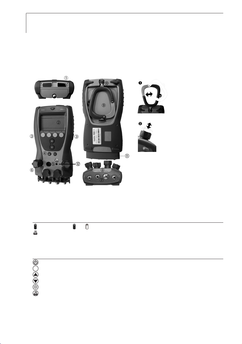
At a glance
IrDA interface (printer),
USB socket (mains unit, PC data transmission).
Display: Low-pressure side (blue), high-pressure side (red)
Display symbols
: Battery capacity ( : full, : empty)
: Print function: sends data
2x mini-DIN probe sockets, with socket cover
Control keys
Key functions
: On/off button: Switching the instrument on/off.
: Function key (4x, orange): shows relevant function on the display.
: Up/down keys: changes display view.
: Light key: Switching the display /inspection glass illumination on/off.
: Print key: Sending data to the Testo protocol printer.
Inspection glass for measuring medium flow.
4x valve positioners, with two setting positions (see ).
Page 9

Product description 9
3x connections 7/16" UNF,
1x connection 5/8" UNF, testo 556-1 / 560-1: Brass, testo 556-2 / 560-2:
Stainless steel. Left /right: Low-pressure / high-pressure, centre: Evacuation
(5/8")/ filling (7/16"), for refrigerant hoses with quick connect fitting, passage
via valve positioner can be locked.
Unlock buttons for valve positioner.
Battery/ radio module compartment. It is not possible to charge
rechargeable batteries in the instrument!
Foldable suspension device, with eyelet for padlock (see ).
Plastic protector
Warning!
Do not remove plastic protector for measurement and transport. It protects the
screw connections of the measuring instrument from breaking off under
mechanical strain.
Automatically opening/closing vacuum protection valve: Protects the
integrated vacuum sensor from too high pressures.
After longer periods of non-use:
In depressurized state, use a blunt object to press the protective valve in, in
order to prevent jamming
Warning!
Danger oof iinjury ddue tto eescaping rrefrigerant
The danger of freezing
(fast evaporation of liquid), poisoning or asphyxiation (displacement
of air oxygen) exists for the user.
i Operate the instrument only with protective equipment (protective
goggles, protective gloves). For ammonia refrigerants, additionally
wear breathing equipment.
i Observe the descriptions of danger and information on protective
equipment in the safety data sheet of the respective refrigerant
use.
i In case of malfunction of the vacuum protection valve: Discontinue
using instrument and send in to Testo customer service.
Warning!
Externally connected instruments and accessories can be damaged by
electromagnetic discharge during the filling process.
en
defresitptsvnl????
Page 10

First steps10
First steps
²
Inserting bbatteries / rechargeable bbatteries/radio mmodule:
Radio probes may only be used in countries in which they are permitted
(see radio probe instructions).
A radio module (accessory part) is required for the use of radio probes.
The instrument can establish a connection with a maximum of two radio
probes.
Each radio probe has a probe ID (RF ID). This consists of the last 3
numbers of the serial no. and the position of the slide switch in the radio
probe (H or L).
1 Fold out the suspension device and open the battery compartment (clip
lock).
2 Insert buffer battery (included in delivery, 1x 3V lithium CR2032) in the
battery compartment. Observe the polarity (positive pole up)!
3 Push radio module (accessory) into the module slot underneath the buffer
battery until the module engages (contact strip facing up).
4 Insert batteries (included in delivery) or rechargeable batteries (4x 1.5V,
type AA / mignon / LR6) into the battery compartment. Observe the
polarity!
5 Close the battery compartment.
When not in use for long period: Read out memory and remove batteries
(not the buffer battery).
When operating the instrument with the mains unit, insert batteries in
order to avoid switching off the instrument in case of a power interruption.
²
Switching tthe iinstrument oon:
i Press .
- Initialization phase:
· All display segments are lit (length of time: 2s).
· Instrument designation, serial number and firmware version are
displayed (duration: 2s).
- Measurement view is opened.
-or-
Page 11

First steps 11
- Switching on the first time after changing the battery: Language is
displayed.
1 Set language using and and confirm entry with OK function key.
- Set the Batterytype (Rech/Bat) is displayed.
The type of battery used must be entered so that the calculation of the
battery capacity is carried out correctly.
2 Set battery type using and and confirm entry with OK function
key.
- Date/time are displayed.
3 Set blinking number with and and change to next number with
and .
4 Confirm the entry with the OK function key.
- The configuration menu is opened.
²
Switching tthe iinstrument ooff:
i Press .
²
Operate vvalve ppositioner:
The function of the valve positioners is independent of the selected setting
position. For easier operation, it is recommended that you unlock the
required valve positioners. For transport, the valve positioners should be
retracted.
i Unlock valve positioners: Press unlock button.
i Retract valve positioner: Press valve positioner into the housing. The
refrigeration system analyzer acts like a conventional four-way manifold
with regard to the refrigerant path. The passages are opened by opening
the valves. The adjacent pressure is measured with valves closed as well
as with them open.
i Open valve: Turn the valve positioner anticlockwise
i Close valve: Turn the valve positioner clockwise.
Warning!
Tighten valve positioner only hand-tight. Do not use tools to tighten
the valve positioner, as the thread may be damaged thereby!
en
defresitptsvnl????
Page 12
Using the product12
Using the product
Setting the instrument
²
Setting tthe iinstrument:
1 Press the Set function key.
- The configuration menu is opened.
2 Select function and set parameters:
Key functions
· : Select function / settings.
· : Select function or change parameters / settings.
·
OK : Activate function or confirm parameters / settings, exit configuration menu.
· Apply : Activate function or confirm parameters / settings, do not exit configuration menu.
· esc : Exit configuration menu (without saving).
Functions and settings / parameters
· P-relative/P-absolute :
· P=0 : Zero pressure sensors.
· pabs, prel : Change between absolute and relative pressure displays.
·
Refrigerant : Set refrigerant.
· R... : Refrigerant number of refrigerant according to ISO817.
· --- : No refrigerant selected.
· Memory :
·
Select installation : Activate customer / system. Select customer ( ), select system ( ).
Symbol * behind the designation: Protocols are stored in the memory.
· Free memory : Display of the free memory space.
· View protocol : Display measurement protocols. Select customer ( ), select system ( ).
Change display view ( ), select protocol ( ).
· Erase memory : Delete Customer, Installation, Protocol or entire memory (All).
·
Alt : Set height. Change blinking number ( ), change between numbers ( ).
· Device settings :
· Units : Set units for Pressure, Temperature, Vacuum, Altitude and Mass. Choose parameter
( ), choose unit ( ).
· Auto off : Switch automatic switch-off off (Off) or on (On) ( ), enter duration (minutes after button
was pressed for the last time) ( ).
·
Date/time (Format dependent upon selected language) : Set date (day, month, year) and time (hours,
minutes).
· Language : Set language (the setting affects the available units and the date format).
· PIN : Enter instrument PIN (protects a running measuring program from manual intervention),
deactivate PIN request (enter ----).
· Recharge/Standard Bat : Set battery type (important for correct calculation of battery capacity).
·
Factory settings : Reset instrument to condition upon delivery. Caution! Memory is deleted.
· Diagnostic : Display instrument data
Page 13
Using the product 13
· Probes :
·
Radio probe select : Carry out search for switched-on radio probes. Select probe ( ), assign
radio probe to low-pressure / high-pressure side (blue or red: Apply), delete probe assignment (select
---- and Apply).
· Probe search : Carry out search for connected probes or other accessories.
· Probe mapping : Assign radio probes / connected probes to the parameters. Select parameter (
), select probe ( or ), assign probe (Apply).
· Saturated steam table : Display saturated steam table. Select refrigerant ( ), change pressure
value ( ).
3 Press OK function key to save the settings and to exit the configuration
menu.
Preparing for measurement
²
Connecting tthe ttemperature pprobe / accessories:
Probes /accessories must be connected before the measuring instrument
is switched on so that they are recognized by the measuring instrument.
If probes / accessories are connected afterwards, a probe search must be
carried out: Set > Probes > Probe search. Alternative (only available in
standard measurement view): Set must be held down for 2s.
If radio probes are to be used, these must first be selected (Set > Probes >
Radio probe select) and assigned (Set > Probes > Probe mapping).
1 Open socket cover on the left / right side of the instrument.
2 Insert the connector of the accessory into the probe socket:
Accessories Measurement task (measurement channel) Socket
Temperature probe (blue) Overheating (toh) or temperature difference (t1) left
Temperature probe (red) Undercooling (tcu) or temperature difference (t2) right
Clamp-on probe* Compressor performance (l) right
Refrigerant scale* Fill / drain (m) right
Oil pressure probe* Oil lubrication of the compressor (px) right
* Option not available as standard. Please ask your local Testo subsidiary.
3 Position accessories according to measurement task:
Measurement task (measurement channel) Position
Overheating (toh) On the end of the evaporator
Undercooling (tcu) On the end of the liquefier
Temperature difference (1) Measured object 1
Temperature difference (t2) Measured object 2
Current measurement (l) On the electrical consumers
Fill / drain (m) On the system
Oil lubrication of the compressor (px) At compressor oil measurement fittings
en
defresitptsvnl????
Page 14
Using the product14
²
Zeroing tthe ppressure ssensors:
Carry out a zeroing of the pressure sensors before every measurement.
The measurement values can be falsified by a change in the position of
the measuring instrument. After zeroing, the position of the measuring
instrument must not be changed. Carry out zeroing before every
measurement in order to compensate faulty positioning or long-term zeropoint drift. Zeroing is only possible in a range of ±1bar(rel)/±14.5psi (rel)
or 0...2bar(abs) / ±29psi (abs).
1 Press Set function key.
- p=0 is displayed.
2 Press OK function key to carry out zeroing.
²
Connect rrefrigerant hhoses:
The valve positioners are closed.
1 Connect refrigerant hoses for low-pressure side (blue) and high-pressure
side (red) to the measuring instrument.
2 Connect refrigerant hoses to the system.
Warning!
If the measuring instrument falls down or is exposed to any other
comparable mechanical strain, the end connections of the refrigerant
hoses can break off. The valve knobs can also be damaged, which
can lead to further damage in the interior of the instrument, which is
not visible externally. For this reason, replace the refrigerant hoses
after any fall or comparable mechanical strain with new, undamaged
refrigerant hoses. For your own safety, send the instrument to Testo
customer service for technical testing.
Page 15

Using the product 15
Measuring
Warning!
Danger oof iinjury ddue tto hhighly ppressurized hhot, ccold oor ppoisonous
refrigerants!
i Always secure the measuring instrument with the carabiner
suspension hook before pressurizing the instrument, in order to
prevent falls (danger of breakage).
i Before each measurement, ensure that the refrigerant hoses are
intact and correctly connected. Do not use tools to connect the
hoses. Connect the hoses only hand-tight (max. torque 5.0Nm/
3.7ft*lb).
i Wear protective glasses and protective gloves.
i Observe permitted pressure range!
²
Measuring:
The steps described in the chapter "Preparing for measurement" have
been completed.
1 Check whether customer / system (assignment of the readings by saving),
pressure display (absolute / relative) and refrigerant are correctly selected,
see the chapter "Setting the instrument".
2 Pressurize the measuring instrument.
3 Read off readings or monitor trend display (next to the readings):
With zeotropic refrigerants, the evaporation temperature to is displayed
after the complete evaporation / is displayed after the complete
condensation tc.
en
defresitptsvnl????
Page 16

Using the product16
Key functions
· : Changing the reading display. The availability of the individual reading displays and the
parameters varies depending on the availability of the measuring signal (probe / accessories
connected, radio probe logged on, probe assigned).
· Function key
Hold/Min/Max : Record readings, display min.-/max. readings (since last switch on or
last reset).
· Function key RESET : Reset min. / max. readings. Only available if min. or max. readings are displayed.
- When critical pressure of refrigerant is reached: Reading and display
illumination blink.
²
Saving rreadings:
1 Press the Save function key.
2 Check if the customer / system are correctly selected,
If necessary: Change customer using change system using
function key.
3 Press OK function key to save.
²
Saving sseries oof rreadings:
1 Press the Save function key.
2 Check if the customer / system are correctly selected,
If necessary: Change customer using change system using
function key.
3 Press the Serial? function key.
________________________________________________________________ ________________________________________________________________
Refrigerant evaporation temperature t
o
Refrigerant condensation temperature t
c
Overheating Δtoh/ t
sh
UndercoolingΔtcu/ t
sc
________________________________________________________________ ________________________________________________________________
________________________________________________________________ ________________________________________________________________
Refrigerant evaporation temperature t
o
Refrigerant condensation temperature t
c
Measured temperature t
oh
Measured temperature t
cu
________________________________________________________________ ________________________________________________________________
________________________________________________________________ ________________________________________________________________
Temperature t
1
Temperature t
3
Temperature t
2
Temperature t
4
________________________________________________________________ ________________________________________________________________
________________________________________________________________ ________________________________________________________________
Evaporation pressure p
o
Condensation pressure p
c
Right probe socket measuring signal
________________________________________________________________ ________________________________________________________________
________________________________________________________________ ________________________________________________________________
Evaporation pressure p
o
Condensation pressure p
c
Refrigerant evaporation temperature t
o
Refrigerant condensation temperature t
c
________________________________________________________________ ________________________________________________________________
Page 17
Using the product 17
4
Enter parameters cycle/ cycle length (min. 2s, max. 60min) and duration
(in hours/ minutes) for series of readings: Set value using change
between parameters using function keys.
5 Confirm the entry with the OK function key.
With active PIN request, see the chapter "Setting the instrument":
i Enter PIN: Set number using , change between the numbers
using function keys.
6 Start the series of readings with the Start function key.
Performing actions
²
Fill oor ddrain:
In principle, the fill and drain actions are the same in terms of process, only
the values change conversely.
The maximum display range for the mass m is: -999.9 ..9999.9kg or.
-9999 ..99999g / lb / oz . Before starting the action, check the correct
setting of the unit, and in case of doubt switch to the “larger” unit (kg/ lb),
as no measurement value is displayed if the display range is exceeded or
fallen short of (display uuuuu/ ooooo).
1 Press the Action function key.
2 Using function keys, select Fill or Vacate and confirm entry using OK
function key.
3 Using set customer, set system using function keys and confirm
entry using OK function key.
4 Set refrigerant using and confirm entry using OK function key.
5 Connect refrigerant scale* to the right probe socket, switch on and
confirm using the OK function key.
* Option not available as standard. Please ask your local Testo subsidiary.
Only for the action Fill: An optional alarm can also be activated that will go
off when a defined fill level is reached (mass m or overheating T) (Alarm
blinks):
i Open input menu (Alarm?). Set alarm value ( : Set number, :
change between the numbers). Activate alarm (OK).
6 Close bottle and set on the scale. Confirm with OK function key.
7 Using the Start function key, start recording the filling or draining process
and open the valve of the the bottle.
en
defresitptsvnl????
Page 18

Using the product18
The option “Changing the reading display” is available, see chapter
“Measuring”.
8 If necessary: Change bottle (Bot. 02, continue with step 6).
9 After completion of the filling or draining process: Stop recording using the
Exit function key and confirm with the OK function key.
²
Macro ((only ttesto 5560):
The macro function serves to measure small pressures (max. 200hPa).
Measurement on the low-pressure side (pv) takes place via the vacuum
sensor (finer resolution). Note permissible pressure range!
1 Press the Action function key.
2 Using function keys, select Macro and confirm entry with the OK
function key.
3 Using set customer, set system using function keys and confirm
entry using OK function key.
The "Change reading display", "Display Hold/Max/Min", "Save reading /
series of readings" options are available, see the chapter "Performing the
measurement".
4 Create necessary connections and carry out macro pressure
measurement.
²
Evacuate ((only ttesto 5560):
Measurement on the low-pressure side (pv) takes place via the vacuum
sensor (finer resolution). Note permissible pressure range!
1 Press the Action function key.
2 Using function keys, select Evacuation and confirm entry with the OK
function key.
3 Using set customer, set system using function keys and confirm
entry using OK function key.
- The refrigerant is automatically set to H2O.
The "Change reading display", "Display Hold/Max/Min", "Save reading /
series of readings" options are available, see the chapter "Performing the
measurement".
4 Create necessary connections and carry out evacuation of the system.
²
Current mmeasurement ((current):
1 Press the Action function key.
2 Using function keys, select Current and confirm entry with the OK
function key.
Page 19

Using the product 19
3
Connect clamp-on probe* to the right probe socket and confirm using the
OK function key.
* Option not available as standard. Please ask your local Testo subsidiary.
The "Change reading display", "Display Hold/Max/Min", "Save reading /
series of readings" options are available, see the chapter "Performing the
measurement".
²
Calculate ppressure ddifference ((differential ppressure):
1 Press the Action function key.
2 Using function keys, select Pressure difference and confirm entry with
the OK function key.
3 Connect oil pressure probe* to the right probe socket and confirm using
the OK function key.
* Option not available as standard. Please ask your local Testo subsidiary.
4 Using the px=0 function key, zero the differential pressure probe
(unpressurized).
A zeroing is only possible in the following area:
±1bar(rel)/±14.5psi (rel) or 0...2bar(abs) / ±29psi (abs).
5 Confirm using OK function key bring probe into circuit.
The "Change reading display", "Display Hold/Max/Min", "Save reading /
series of readings" options are available, see the chapter "Performing the
measurement".
en
defresitptsvnl????
Page 20

Maintaining the product20
Maintaining the product
±
Cleaning tthe hhousing:
i If dirty, clean the housing with a damp cloth (soap solution). Do not use
aggressive cleaning products! Immediately remove oils, refrigerants and
solvents from the housing.!
±
Keep cconnections cclean:
i Keep screw connections clean and free of grease and other deposits,
clean with a moist cloth as required.
±
Regularly rreplace rrefrigerant hhoses
Warning!
If the measuring instrument falls down or is exposed to any other
comparable mechanical strain, the end connections of the refrigerant
hoses can break off. The valve knobs can also be damaged, which
can lead to further damage in the interior of the instrument, which is
not visible externally. For this reason, replace the refrigerant hoses
after any fall or comparable mechanical strain with new, undamaged
refrigerant hoses. For your own safety, send the instrument to Testo
customer service for technical testing.
±
Remove ooil rresidues:
i Carefully blow out oil residues in valve block using compressed air.
±
Ensure aaccuracy oof mmeasurement:
Testo customer service would be glad to further assist you if you so wish.
i Check instrument regularly for leaks (Recommended: annually). Keep to
the permissible pressure range!
i Calibrate instrument regularly (Recommended: annually).
±
Changing tthe bbatteries //rechargeable bbatteries //radio mmodule:
Instrument is switched off.
i Before removing the batteries: Read out memory to avoid data loss.
1 Fold out the suspension device and open the battery compartment (clip
lock).
2 Remove empty batteries / rechargeable batteries, empty buffer battery or
radio module.
Page 21

Maintaining the product 21
3
Insert batteries / rechargeable batteries, empty buffer battery battery, radio
module:
i Push radio module into the module slot underneath the buffer battery
(contact strip facing up).
i Insert new batteries / rechargeable batteries (4x 1.5V, type AA, mignon,
LR6). Observe the polarity!
i Insert new buffer battery (1x 3V lithium CR2032) in the battery
compartment. Observe the polarity (positive pole up)!
5 Close the battery compartment.
6 Set battery type and check / set date / time, see the chapter "First steps",
"Switch instrument on".
±
Replacing tthe vvalve oor tthe ppositioner kknob:
Warning!
Replacing of the positioner knob and the valve by the customer is not
allowed. Send the instrument to Testo customer service.
en
defresitptsvnl????
Page 22

Tips and assistance22
Tips and assistance
Questions and answers
Question Possible causes Possible solution
flashes. · Batteries are almost empty. · Change batteries.
Instrument switches ·
Auto Off function is switched on. · Switch function off.
itself off. · Residual capacity of the batteries is too low. · Change batteries.
uuuu illuminates instead · Permitted measuring range · Keep to the permitted measuring range.
of parameter display. was undershot.
oooo illuminates instead · Permitted measuring range · Keep to the permitted measuring range.
of parameter display. was exceeded.
---- illuminates instead · Probe not connected. · Connect probe.
of parameter display. · Probe break. · Replace probe.
Refrigerant escaping · Valve positioner not tight · Please contact your dealer
from valve positioner or Testo cutomer service.
testo 560 only
Evacuation function:
ooooo is displayed instead · connected pressure higher than · decrease pressure
of meas. parameter, despite atmospheric pressure · reset vacuum protection valve
vacuum is < 200 mbar · protective valve of vacuum (see arrow) with a blunt object
sensor has been triggered
If we could not answer your question, please contact your dealer or Testo
Customer Service. For contact data, see back of this document or web page
www.testo.com/service-contact
Page 23

Tips and assistance 23
Accessories and spare parts
Designation Article no.
Probe
Air probe, PT100 0609 1773
Surface probe, PT100 0609 1973
Immersion / penetration probe, PT100 0609 1273
Pipe wrap probe, PT100, with Velcro tape, 2.9m pipe 0609 5602
Pipe wrap probe, PT100, with spring clamping device 0609 5605
Miscellaneous
Refrigerant scale * 0554 5606
Clamp-on probe * 0554 5607
Oil pressure probe * 0638 1742
easyKool PC software 0554 5604
USB data transmission cable, instrument - PC 0449 0047
Padlock for instrument security 0554 1747
Stainless steel adapter for NH3(ammonia), 3x 7/16“ on 1/2“, 1x 5/8“ on 1/2“ 0554 5561
Protocol printer, IrDA 0554 0547
* Option not available as standard. Please ask your local Testo subsidiary.
For a complete list of all accessories, please refer to the product catalogs and
brochures or look up our website at: www.testo.com
en
defresitptsvnl????
Page 24

0970 5601 en 08 V02.01
 Loading...