

Page 1
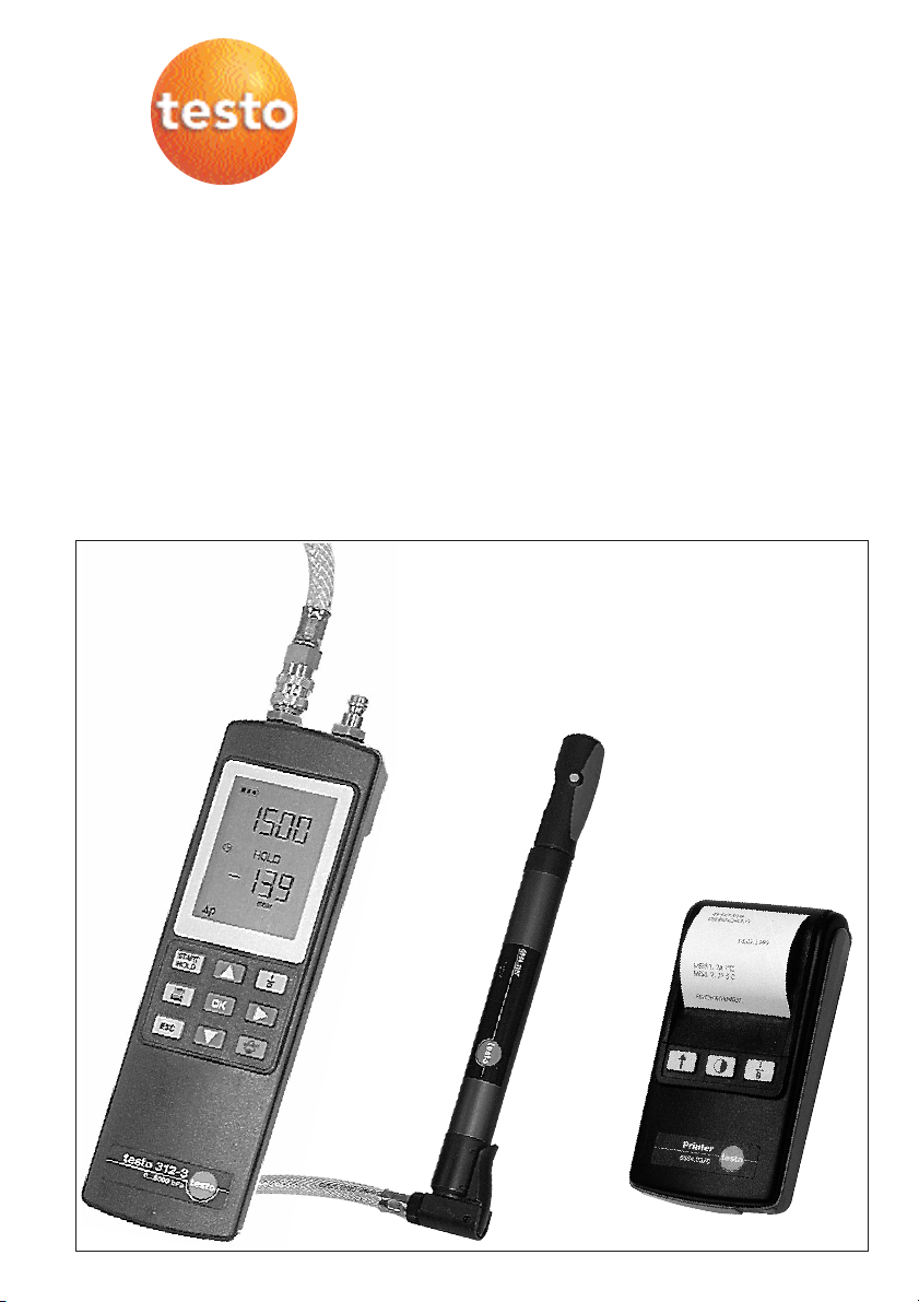
testo 312 - 2/3
Instruction manual
www.GlobalTestSupply.com
Page 2

Contents
Introduction2
Initial operation . . . . . . . . . . . . . . . . . . . . . . . . . . . . . . . . . . . . . . . . . . . . . . . . . . . . . . . . . . . . 3
Warnings . . . . . . . . . . . . . . . . . . . . . . . . . . . . . . . . . . . . . . . . . . . . . . . . . . . . . . . . . . . . . . . 3
Safety instructions . . . . . . . . . . . . . . . . . . . . . . . . . . . . . . . . . . . . . . . . . . . . . . . . . . . . . . . . 3
Diagram of instrument . . . . . . . . . . . . . . . . . . . . . . . . . . . . . . . . . . . . . . . . . . . . . . . . . . . . . 4
Operating the instrument . . . . . . . . . . . . . . . . . . . . . . . . . . . . . . . . . . . . . . . . . . . . . . . . . . . 5
Measurement example . . . . . . . . . . . . . . . . . . . . . . . . . . . . . . . . . . . . . . . . . . . . . . . . . . . . . . 6
Switching on instrument . . . . . . . . . . . . . . . . . . . . . . . . . . . . . . . . . . . . . . . . . . . . . . . . . . . . 6
Differential pressure measurement . . . . . . . . . . . . . . . . . . . . . . . . . . . . . . . . . . . . . . . . . . . . 7
Fine pressure/Draught measurement . . . . . . . . . . . . . . . . . . . . . . . . . . . . . . . . . . . . . . . . . . 8
Connection options . . . . . . . . . . . . . . . . . . . . . . . . . . . . . . . . . . . . . . . . . . . . . . . . . . . . . . . 9
Pre-test / Main test. . . . . . . . . . . . . . . . . . . . . . . . . . . . . . . . . . . . . . . . . . . . . . . . . . . . . . . 10
Service ability test. . . . . . . . . . . . . . . . . . . . . . . . . . . . . . . . . . . . . . . . . . . . . . . . . . . . . . . . 11
Setting alarm limits . . . . . . . . . . . . . . . . . . . . . . . . . . . . . . . . . . . . . . . . . . . . . . . . . . . . . . . . 12
Setting date/time . . . . . . . . . . . . . . . . . . . . . . . . . . . . . . . . . . . . . . . . . . . . . . . . . . . . . . . . . . 13
Setting timer for printout . . . . . . . . . . . . . . . . . . . . . . . . . . . . . . . . . . . . . . . . . . . . . . . . . . . . 15
Setting number of printouts . . . . . . . . . . . . . . . . . . . . . . . . . . . . . . . . . . . . . . . . . . . . . . . . . 16
Changing the units . . . . . . . . . . . . . . . . . . . . . . . . . . . . . . . . . . . . . . . . . . . . . . . . . . . . . . . . 17
Maintenance . . . . . . . . . . . . . . . . . . . . . . . . . . . . . . . . . . . . . . . . . . . . . . . . . . . . . . . . . . . . . 18
Changing rechargeable battery or battery . . . . . . . . . . . . . . . . . . . . . . . . . . . . . . . . . . . . . . 18
Error messages . . . . . . . . . . . . . . . . . . . . . . . . . . . . . . . . . . . . . . . . . . . . . . . . . . . . . . . . . . . 18
Technical data . . . . . . . . . . . . . . . . . . . . . . . . . . . . . . . . . . . . . . . . . . . . . . . . . . . . . . . . . . . . 19
Ordering data. . . . . . . . . . . . . . . . . . . . . . . . . . . . . . . . . . . . . . . . . . . . . . . . . . . . . . . . . . . . . 20
Pressure transducer (Accessories). . . . . . . . . . . . . . . . . . . . . . . . . . . . . . . . . . . . . . . . . . . . 21
Introduction
Dear Customer
You have made the right decision by purchasing testo 312.
testo 312 is designed to adjust and maintain gas heating systems.
Thousands of customers buy our high standard products every year. There are at least 7 good
reasons for doing so.
1) Cost-performance ratio. Reliable quality at a fair price.
2) Extended warranty times of up to 3 years - depending on instrument!
3) We have the ideal solutions for your measuring tasks based on our expert experience gained
over 40 years.
4) Our high quality standard is confirmed by the ISO 9001 certificate.
5) Of course, our instruments carry the CE symbol required by the EU.
6) Calibration certificates for all relevant parameters. Seminars, advice and calibration on location.
7) Our after-sales service. Contact us for more information.
Instrument conforms with 2004/108/EEC
2
www.GlobalTestSupply.com
Page 3

Initial operation
Warnings
Function check/Leak check
Prior the commencing any testing the complete
measuring system (intrument, probe and hoses) should
be checked for leaks
Temperature influence on the leak test
During any leak tests the ambient temperature must
remain constant to obtain valid data.
Instrument should only be used by trained personnel.
Always adhere to any system safety instructions and
never use the equipment in an explosive environment.
Function test
for both pressure nipples
++
No reading in display?
Send instrument for service.
www.GlobalTestSupply.com
Safety instructions
Under normal operating conditions gas will not escape
from the instrument when connected to the gas pipe /
system under test.
The instrument is not designed to operate while wet, or
in an environment of condensing humidity
The instrument should only be used in the conditions
and for the purposes for which it was constructed.
Please take particular note of the safety instructions
and the technical data.
The instrument should only be used in the operation and
measurement ranges specified in the technical data.
Capacity display
Voltage >7.2 V
Life of rechargeable battery: approx. 5 h
Life of battery: approx. 15 h
(at an ambient temperature of 20°C)
Flashing symbol, voltage: <7.2 V
Life of rechargeable battery: approx. 15 min.
Low Bat
Life of battery: approx. 45 min.
If the rechargeable battery voltage drops below
6.7 V automatic switch-off follows as protection
against total discharge.
3
Page 4

Symbol for alarm
On/Off
Alarm levels
Print
Battery capacity
Time
Measuring units
Date/Time
Initial operation
Diagram of instrument
Pressure
connection
Parameters
Readings
Measuring units
Start
measurement/
Freeze readings
Print button
OK button
Cancel/Restore
Freeze readings
Parameters
Parameters
On/Off button
Scroll buttons
Audible alarm
On/Off button
4
www.GlobalTestSupply.com
Page 5

Initial operation
Operating the instrument
Keypad
- Scrolling buttons
Using the arrow buttons / you can scroll
between the parameters, digits in date/time and the alarm
limits can be set.
- Selection button
In the date/time and alarm limits menu, access to the
variable parameters is via the arrow button pointing to the
right .
The units can also be changed. The parameters are set
using the up and down buttons.
- Printing
All of the saved readings can be printed on the printer by
pressing Print .
- I/O button
The instrument is switched on or off via the I/O button
. The display switches off automatically after 5
seconds once the instrument is switched off. This can be
prevented by pressing any button. The instrument then
goes to the Δp measurement menu.
The readings in the display are usually lost when the
instrument is switched off.
- Cancel button
The Cancel button is used to cancel a selected
process or to leave a sub-menu.
- OK button
The changed parameters are saved by pressing .
- START/HOLD button
Start measurement by pressing . The displayed
readings are frozen by pressing again
- Alarm on/off button
Switches audible signal on or off.
5
www.GlobalTestSupply.com
.
Page 6

Connect hose.
Display for
battery
capacity /
instrument version
9.0
Instrument
version
9.0
Measurement example: testo 312-2/-3
Switching on instrument
Self-test
3 s
Self-test
Press button. Displays all segments for
approx. 3 seconds.
Battery capacity / Instrument version (2 digit)
Displays battery/rechargeable battery voltage
and instrument version for approx. 3 seconds.
1.0
3 s
Measurement menu
08:38
--------
1.00
3 s
5 s
www.GlobalTestSupply.com
Instrument version (3 digit)
If the button is pressed within 3 seconds
the version number is shown in 3 digits. You then
go to the measurement menu.
Instrument switches off
6
Page 7
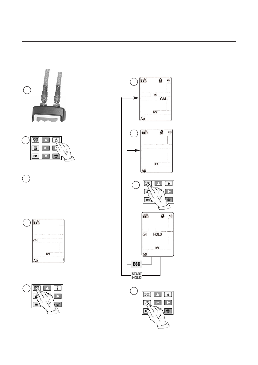
Measurement example: testo 312-2/-3
Differential pressure measurement
testo 312-2: Range: 0 to 200 hPa. Resolution: 0.1 hPa
testo 312-3: Range: 0 to 6000 hPa. Resolution: 1 hPa
1
2
- Segment test (3 s)
3
- Voltage display (3 s)
(see page 6)
Measurement
menu
4
08:38
-----
Connect
pressure
measuring
hose
Switch on
instrument
6
08:38
Wait on calibration
phase (5 s)
2
7
09:15
13.0
8
Position pressure
measurement hose. The
reading appears in the
display.
Save reading.
HOLD appears in
display.
09:15
13.0
5
Start measurement
www.GlobalTestSupply.com
9
7
The saved readings can
be printed.
Page 8
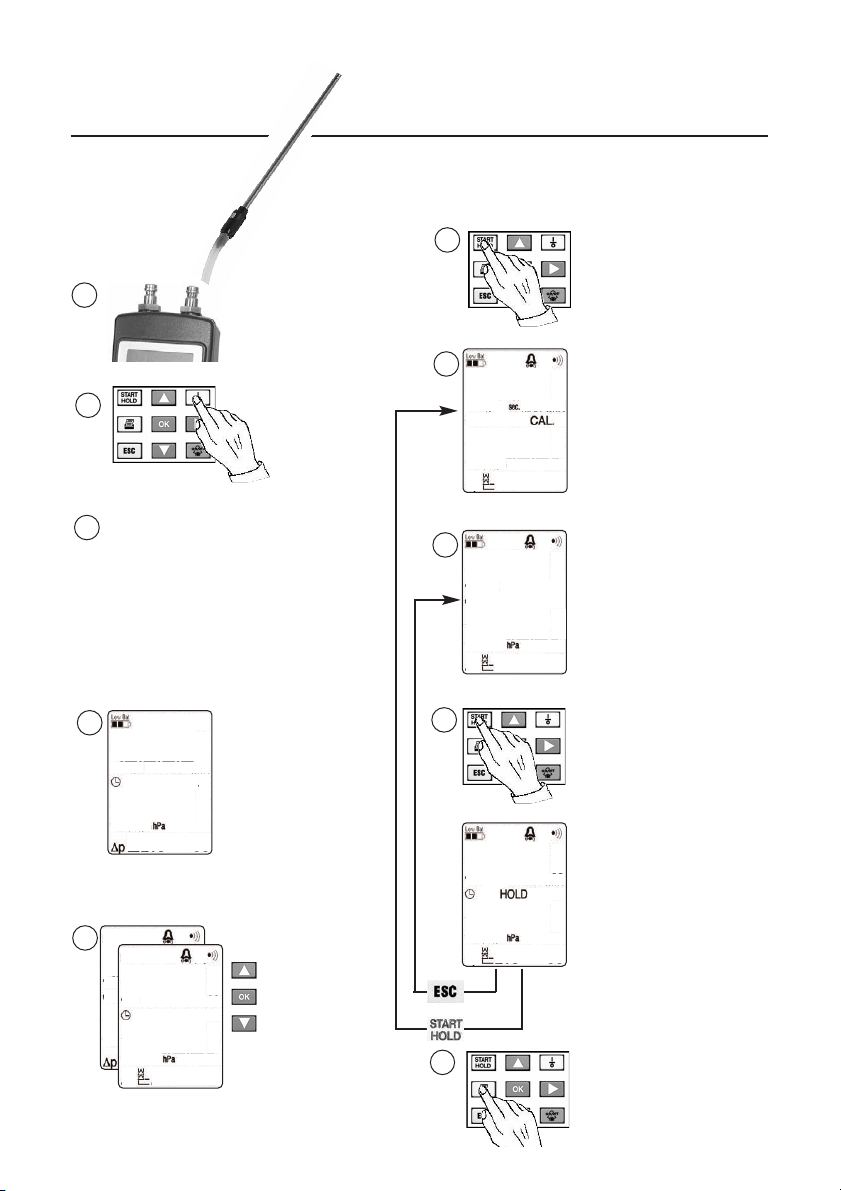
1
2
- Segment test (3 s)
3
- Voltage display (3 s)
(See page 6)
- Function check
(See page 7)
Measurement
menu
4
08:38
Measurement example: testo 312-2
Fine pressure / Draught measurement
testo 312-2: ΔP range 0 to 40 hPa. Resolution: 0.01 hPa
testo 312-3: ΔP range 0 to 300 hPa. Resolution: 0.1 hPa
6
Start measurement.
Connect
probe.
7
09:25
Switch on
instrument.
Wait on calibration
phase (5 s)
2
8
09:25
Position probe in flue
gas duct. The reading
appears in the display.
- 0.24
9
Save reading.
HOLD appears in the
display
-----
Measurement
menu
5
--
-----
152
08:38
09:25
13.0
Measurement
menu selection
with arrow
button.
10
8
www.GlobalTestSupply.com
The saved readings
can be printed.
Page 9
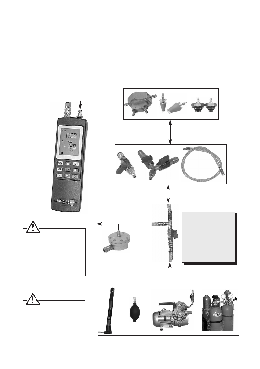
Measurement example: testo 312-2/-3
Connection options
Connect pressure transducer
directly to instrument. Do not
use extensions. Apply
pressure.
Remove pressure from pipe
before detaching pressure
transducer from instrument.
Single-pipe
counter cap
JunctionMini valve
Pressure
drop set
Pressure transducer (for liquid
substances); Refer to instructions
on page 22.
Conical
test plugs
High pressure
stepped plugs
Connection hose
Suitable for:
- Pre-test
- Main test
- Testing service ability
- Checking pressure in
water pipelines
Observe maximum pressure
range.
Positive pressure destroys the
instrument.
Testing
pump
Balloon
pump
Compressor Inert gas
9
www.GlobalTestSupply.com
Page 10
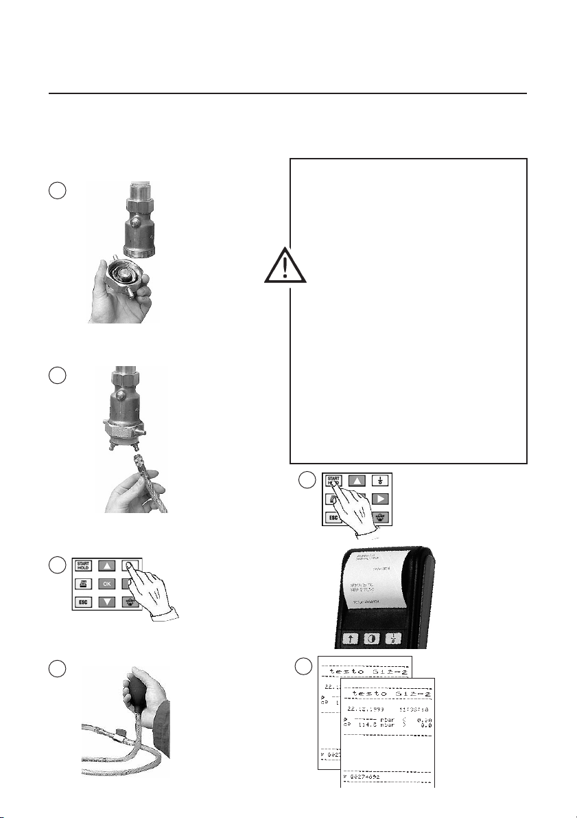
Measurement example: testo 312-2/-3
Pre-test / Main test
Carry out function test! Gas should not
1
2
Example
Insert singlepipe counter
cap and
tighten.
Ensure
connection is
correct.
Connect
pressure drop
set and
testo 312.
get into the instrument when carrying
out measurements on gas pipes.
Pressure drop
The complete measuring system
(instrument, probe, hoses and connec-
tions) should be checked for a drop in
pressure e.g. using pressure drop test
set by attaching the single-valve stop.
Preliminary test
Pipes are checked, without fittings, with a
test pressure of 1 bar. This pressure should
not fall during the 10-minute duration of
the test.
Main test
Pipes are checked, with fittings, with a
test pressure of 110 mbar. This pressure
should not fall during the 10-minute
duration of the test. The measuring
instrument should be able to recognise
a drop in pressure of 0.1 mbar.
5
Manual printout
triggers an
automatic
printout after 10
3
4
Switch on
instrument.
Start measurement
with START/HOLD
button.
6
Build up test
pressure
10
www.GlobalTestSupply.com
minutes.
Compare
printouts
OK/not OK
Page 11
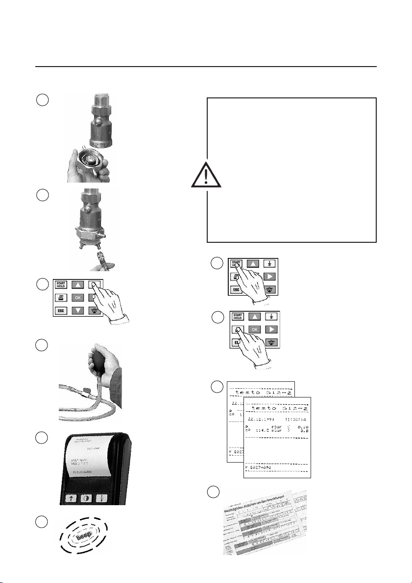
Measurement example: testo 312-2/-3
Service ability test
1
Insert singlepipe counter
cap and
tighten.
2
3
Ensure
connection is
correct.
Connect
pressure drop
set and
testo 312.
Switch on
instrument.
Start
measurement
with
START/HOLD
button.
Carry out function test! Gas should not
get into the instrument when carrying
out measurements on gas pipes.
Pressure drop
The complete measuring system
(instrument, probe, hoses and
connections) should be checked for a
drop in pressure e.g. using pressure
drop test set by attaching the single-
valve stop.
Checking if fit for use
The pipe is pumped with air up to the
respective test pressure and the drop in
pressure in one minute is measured.
7
8
Freeze reading
with START/HOLD
Prints reading
4
Build up test
pressure.
9
Determines Δp
45
5
Printout of initial
pressure
6
Audible signal
after 1 min
www.GlobalTestSupply.com
11
10
Use slide rule
to determine
what measure
to take
Page 12
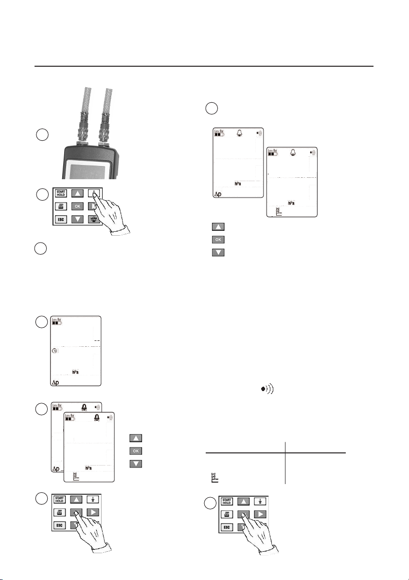
Setting alarm limits
Differential pressure (testo 312-2/-3),
draught (testo 312-2)
7
Differential pressure
1
Draught
08:51
2
- Segment test (3 s)
3
- Voltage display (3 s)
(See page 6)
Measurement
menu
4
08:54
-----
5
-----
08:54
--
-----
Switch on
instrument.
Measurement
menu
selection via
arrow button.
100.0
08:54
- 0.04
Increase or decrease
alarm limits via arrow
buttons.
After the measurement, the flashing is a sign
that an alarm limit is set and was reached.
Note:
If the alarm limit has a value of 0.00 or 0.0,
the alarm of the corresponding alarm limit is
switched off. The dP or draught alarm is
inactivated following initialisation. Alarm
symbols do not appear on the display.
The alarm is deactivated by the manufacturer
i.e. the alarm limit is set at 0.00 or 0.0.
Press the alarm button once the alarm limit is
changed. The symbol is visible.
Alarm setting range
testo 312-2
Δ
P
0 to 200 0 to 6000
0 to -40 0 to 300
testo 312-3
6
www.GlobalTestSupply.com
12
8
Go automatically to
measurement menu.
Page 13
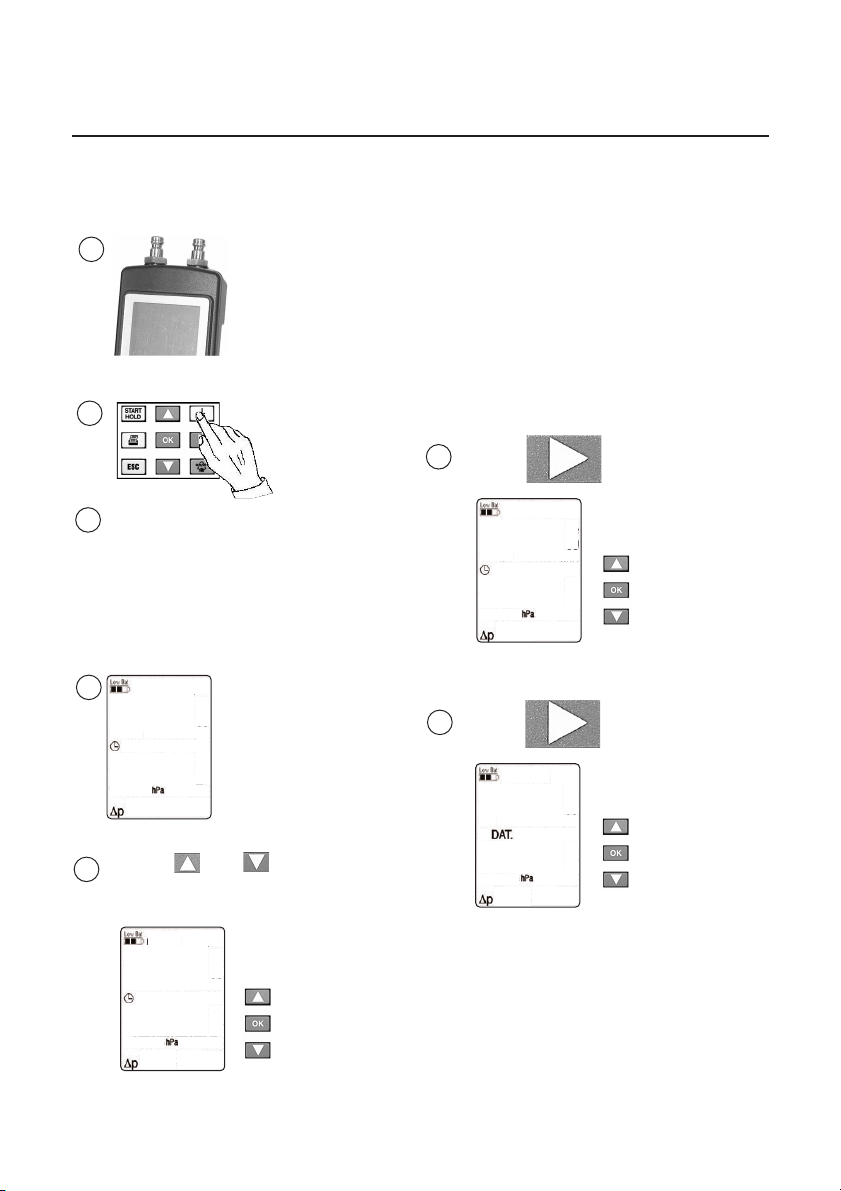
Setting date/time
1
2
- Segment test (3 s)
3
- Voltage display (3 s)
(See page 6)
Measurement
menu
4
08:34
-----
Press and buttons
5
simultaneously.
08:35
-----
Switch on
instrument
Setting the hour
Increase or
decrease digit
with arrow
buttons.
Return to
measurement
menu via OK
6
Press button.
08:35
-----
Press button
7
02.06
-----
Setting minutes
Increase or
decrease digit
with arrow
buttons. Press
OK button to
return to
measurement
menu
Setting the day
Increase or
decrease digit
with arrow
buttons. Press
OK button to
return to
measurement
menu
13
www.GlobalTestSupply.com
Page 14
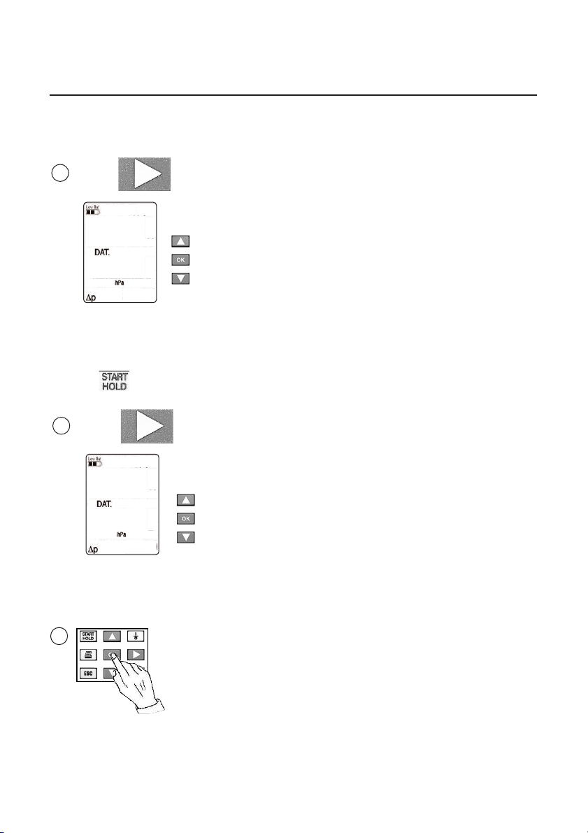
Press button
8
Setting the month
02:06
-----
Note:
The date display can be changed from
Day/Month (EUR) to Month/Day (US) by
pressing
Press button.
9
.
1999
-----
Increase or
decrease digit
with arrow
buttons. Press
OK button to
return to
measurement
menu.
Setting the year
Increase or
decrease digit
with arrow
buttons. Press
OK button to
return to
measurement
menu.
Setting date/time
10
Note
You can leave the menu by pressing ESC
but the changes are not carried out.
Save selection with
OK button.
Return to
measurement menu
selection.
www.GlobalTestSupply.com
14
Page 15
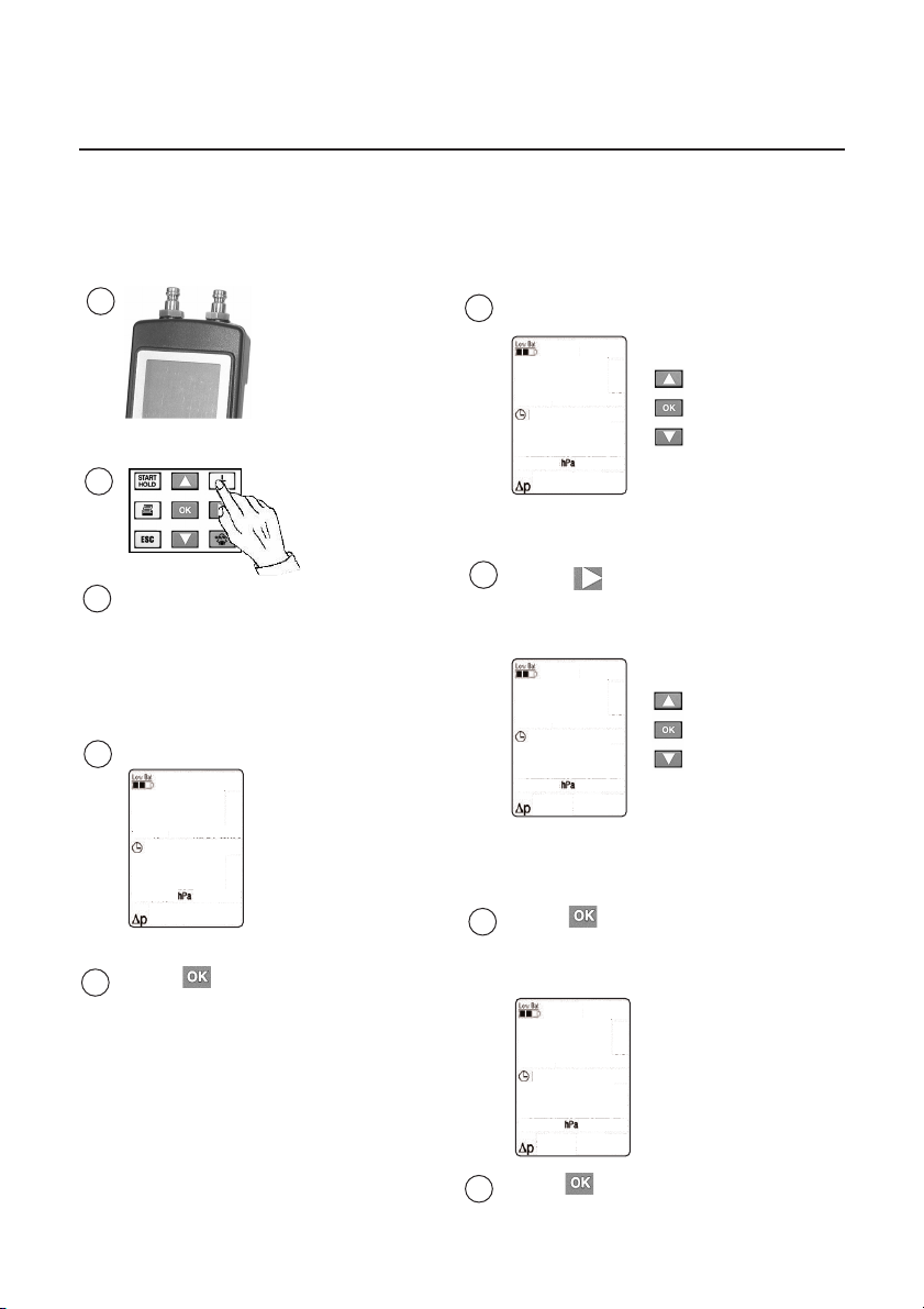
Setting timer for printout
1
2
- Segment test (3 sec.)
3
- Voltage display (3 sec.)
(See page 6)
Measurement
4
menu
08:34
-----
Switch on
instrument
6
Timer
setting
08:35
00
7
Press button.
Timer
setting
08:35
05
8
Press button.
Increase or
reduce value
using arrow
buttons.
Increase or
reduce value
using arrow
buttons.
5
Press button 2 sec.
Alarm limit
display
08:35
205
9
Press button. Return to
measurement menu.
15
www.GlobalTestSupply.com
Page 16
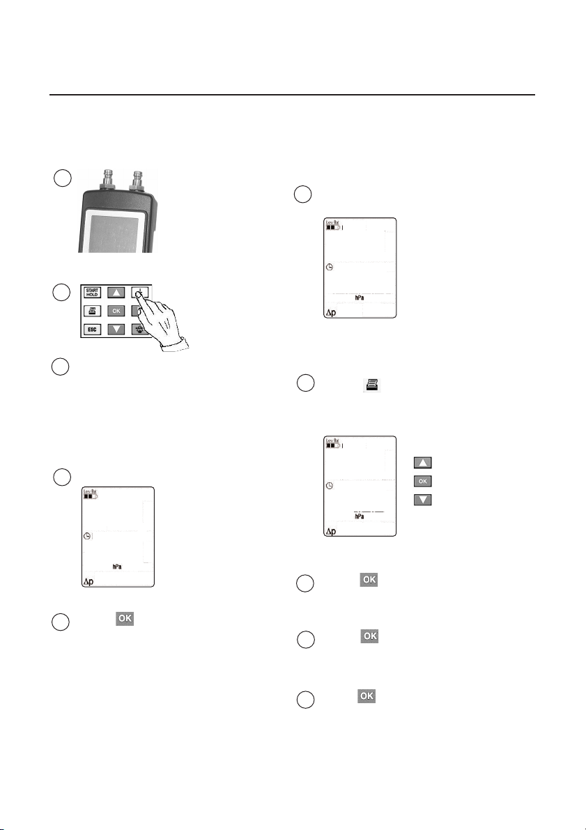
Setting number of printouts
1
6
Display timer
08:35
2
- Segment test (3 sec.)
3
- Voltage display (3 sec.)
(See page 6)
Measurement
4
menu
08:34
-----
5
Press button 2 sec.
Switch on
instrument
15
7
Press button
Set number of
printouts
08:35
2
8
Press button
Timer display
9
Press button
Alarm limit display
Increase or
reduce
number using
arrow buttons.
Press button. Return to
10
measurement menu.
16
www.GlobalTestSupply.com
Page 17
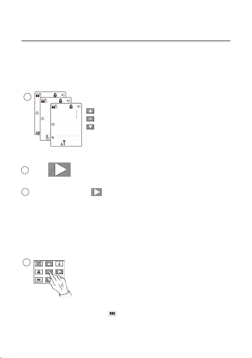
Measurement menu
1
Changing the units
08:57
-
- 20.4
Press button
2
Select units by pressing :
3
Differential pressure measurement
hPa, mbar, mmH
Draught measurement
hPa, mbar, mmH2O, inchH2O (testo 312-2 only)
4
2
O, inchH2O
Selection saved.
Return to measurement
menu.
Measurement
menu
selection with
arrow button.
You can leave the menu by pressing but
the changes are not made.
www.GlobalTestSupply.com
17
Page 18
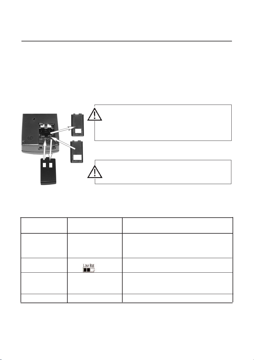
Maintenance
Changing the rechargeable battery or battery
Remove rechargeable batteries/batteries if the instrument
is not used for a longer period of time. If the battery cells
leak in the instrument, return instrument to factory to be
cleaned and checked.
Only the rechargeable batteries/batteries specified in the
technical data should be used.
Switch off instrument and disconnect from all
measuring circuits before changing the rechargeable
2
old
3
Date and time are saved when the instrument is switched
Remove empty/defect rechargeable batteries or empty
batteries from the battery compartment and replace with
new
4
1
new ones.
Observe correct polarisation of rechargeable batteries or
batteries.
Instrument should only be used if the battery
compartment cover is closed.
battery or battery.
off.
Error messages
Phase Symbol Cause
General Low Bat is flashing Power to instrument is too low. If the
battery voltage drops below 6.7 volt, the
instrument switches off automatically.
T in top line is Non-permitted ambient temperature
flashing Adapt to ambient temperature.
The message Send instrument for service.
Exxx appears in the
bottom line
-- -- -- -- Pressure sensor is overloaded.
If we were unable to answer your question, please contact your distributor or Testo
Customer Service. For contact data, see back of this document or web page
www.testo.com/service-contact
18
www.GlobalTestSupply.com
Page 19
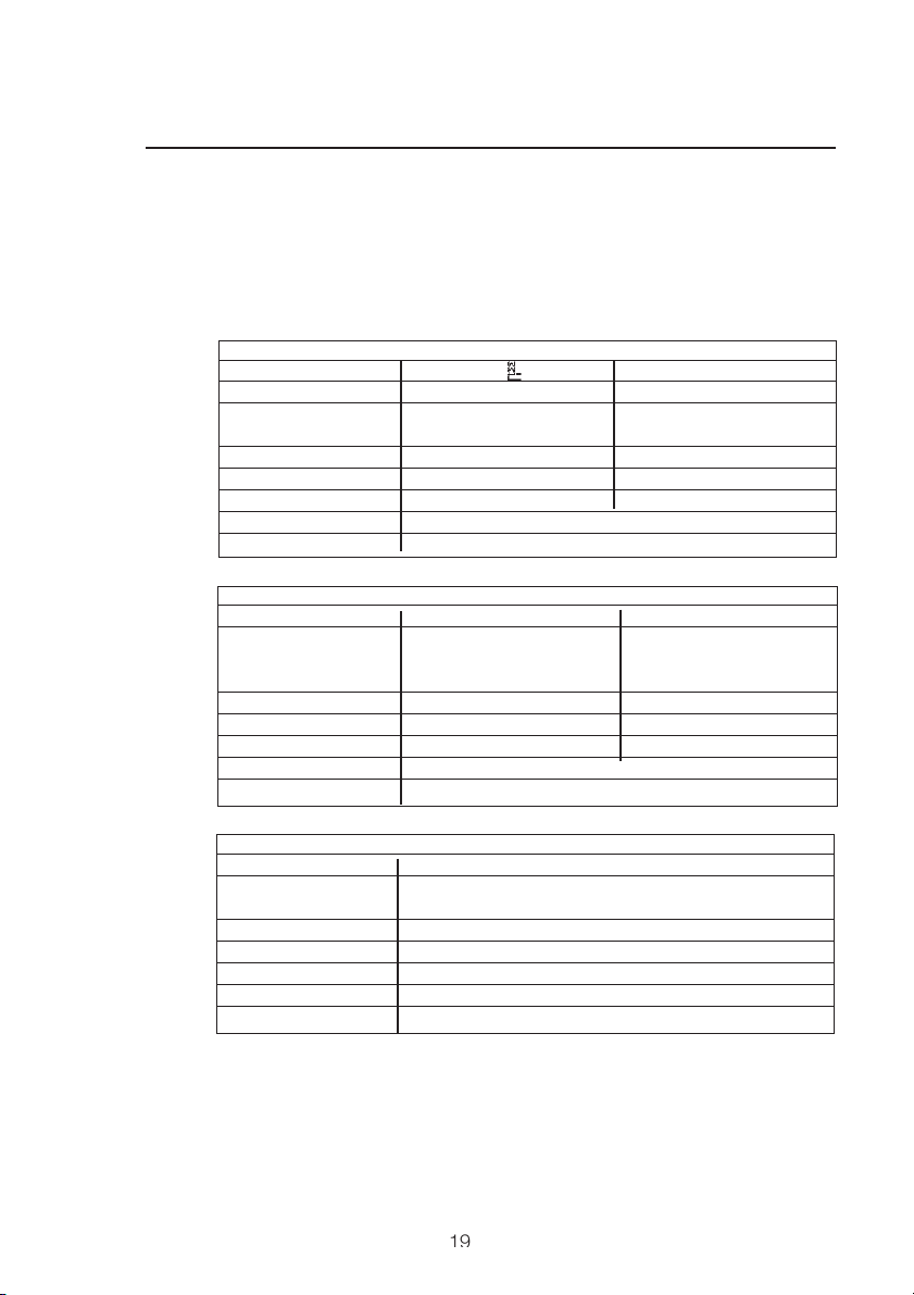
Technical data
testo 312
General Technical data for testo 312-2 and testo 312-3
Storage temperature: -20 to +60 °C
Operation temperature: +5 to +45 °C
Dimensions: 215mm x 68mm x 47mm
Weight: Approx. 400 g
Differential pressure measurement
testo 312-2
Δ
Measuring range* ±40 hPa ±200 hPa
Accuracy** <3.00 hPa ±0.03 hPa ±0.5 hPa (0 to 50 hPa)
>3.00 hPa ±1.5% of m.v.±1,5% of m.v. (>50 hPa)
Resolution ±0.01 hPa ±0.1 hPa
Alarm limit -0.01 to -40 hPa 0.1 to 200 hPa
Adjustment step 0.01 hPa 0.1 hPa
Alarm display Audible and optical
Max. overload 1 bar
testo 312-3
Measuring range* ±300 hPa ±6000 hPa
Accuracy** ±0.5 hPa <50 hPa ±4 hPa <400 hPa
±1.5% of m.v. ≥ 50 h Pa ±2% of m.v. 400-2000 hPa
±4% of m.v. >2000 hPa
Resolution ±0.1 hPa ±1 hPa
Alarm limit 0.1 to 300 hPa 1 to 6000 hPa
Adjustment step 0.1 hPa 1 hPa
Alarm display Acoustic and optical
Max. overload 8 bar
Draught (testo 312-2 only)
testo 312-2
Measuring range* ±40 hPa
Accuracy** <3.00 hPa ±0.03 hPa
>3.00 hPa ±1.5% of m.v.
Resolution ±0.01 hPa
Alarm limit -0.01 to -40 hPa
Adjustment step 0.01 hPa
Alarm display Audible and optical
Max. overload 1 bar
* Measuring instrument is temperature-compensated
** Accuracies do not apply in connection with pressure transducers
0554.3159 and 0554.3168
Warranty
Instrument: 2 years
Probes: 1 year
Accessories 6 months
Printer 1 year (excluding printing mechanism)
P
19
www.GlobalTestSupply.com
Page 20

Ordering data
testo 312
Description
Instrument
testo 312-2 compact pressure gauge with
instruction manual and battery 0632.0313
testo 312-3 compact pressure gauge with
instruction manual and battery 0632.0314
Accessories
Testo printer, prints measurement data with location,
date and time 0554.0547
Spare rolls for printer 0554.0569
Rechargeable battery for printer (4 off) 0515.3120
Rechargeable battery 9V for instrument 0515.0025
Recharger for 9 V rechargeable battery 0554.0025
Recharger for printer 0554.0110
Pressure set with flue probe 0554.3150
TopSafe, indestructible protection case 0516.0443
Case 0516.0191
Service case 0516.3120
Pressure drop test set, 200 mbar 0554.3153
Test pump for pressure drop test set 0554.3157
Single-pipe counter cap 0554.3156
Two-valve junction 0554.3161
Single-valve stop 0554.3162
Connection hose LW6 0554.3158
Conical test plug 16-32mm 0554.3151
Conical test plug 24-44mm 0554.3155
Conical test plug 35-65mm 0554.3152
High pressure stepped plug 3/8” and 3/4” 0554.3163
High pressure stepped plug 1/2” and 1” 0554.3164
Complete high pressure set with case 0554.3160
Pressure transducer for liquid substances, 1 to 6000 mbar 0554.3159
Pressure transducer for liquid substances, 1 to 1000 mbar 0554.3168
System case 0554.3165
Leak detection spray 0554.3166
Slide rule 0554.3169
Test system set 0563.0314
20
Part no.
www.GlobalTestSupply.com
Page 21
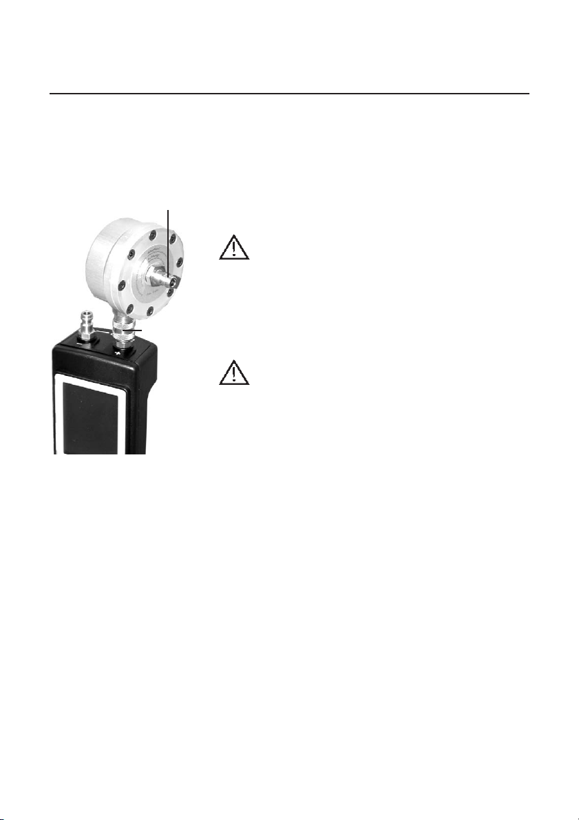
Connection P
Connection
A
Pressure transducer (Accessories)
Instructions
Normal use
The pressure transducer protects the testo 312
measuring instrument from moisture and high
temperatures: measures vapour and water pressure.
Measuring
Do not use an extension cable between the pressure
transducer and the instrument.
1 Connect connection A of the pressure transducer
directly to the instrument (+).
2 Switch on instrument.
3 Press “Start” and wait for calibration phase (5s).
4 Connect connection P of the pressure transducer
directly to the control pressure pipe.
Observe maximum pressure range of instrument and the
pressure transducer used!
5 Apply pressure to pipe.
6 Take readings.
7 Press “Hold”.
8 Remove pressure from pipe.
9 Disconnect pressure transducer from instrument.
Technical data
Connection size: ..........1/8” plug-in connection
Size
(Height/Diameter): ........33mm/64.8mm
Weight: ........................175g
Housing material:..........Aluminium
Pressure range: ............0-1bar (0554.3168)
....................................0-6bar (0554.3159)
Pressure loss: ..............0 to 6% of reading
Diaphragm: ..................Temperature resistant to 120°C,
....................................oil resisting
Overload:......................2bar (0554.3168)
....................................8bar (0554.3159)
21
www.GlobalTestSupply.com
Page 22

testo AG
Postfach 11 40, 79849 Lenzkirch
Testo-Straße 1, 79853 Lenzkirch
Telefon: (07653) 681-0
Fax: (07653) 681-100
E-Mail: [email protected]
Internet: http://www.testo.com
www.GlobalTestSupply.com
0973 3124 en 02 V01.04 en_DE
 Loading...