

Page 1
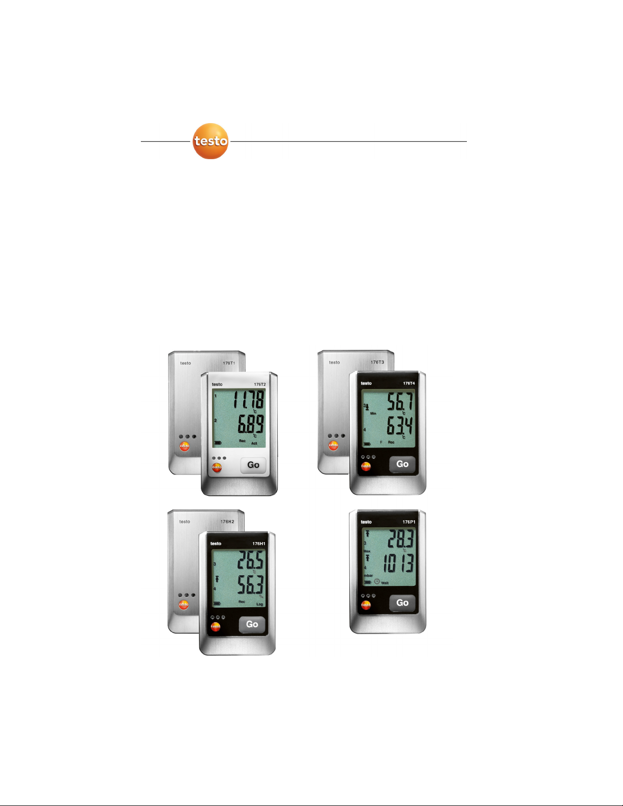
testo 176 · Datenlogger
Bedienungsanleitung
testo 176 · Data loggers
Instruction manual
testo 176 · Enregistreur de données
Mode d'emploi
Find Quality Products Online at: [email protected]
www.GlobalTestSupply.com
Page 2

1 Contents
1 Contents
1 Contents .................................................................................................31
2 Safety and the environment..................................................................32
2.1. About this document......................................................................32
2.2. Ensure safety.................................................................................33
2.3. Protecting the environment............................................................33
3 Specifications ........................................................................................34
3.1. Use ................................................................................................34
3.2. Technical data ...............................................................................35
4 First steps ..............................................................................................43
4.1. Unlock the data logger...................................................................43
4.2. Connecting the data logger to PC..................................................43
5 Display and control elements...............................................................44
5.1. Display...........................................................................................44
5.2. LED ...............................................................................................47
5.3. Key functions.................................................................................48
6 Using the product..................................................................................49
6.1. Connecting a sensor......................................................................49
6.2. Programming data logger ..............................................................49
6.3. Menu overview ..............................................................................50
6.4. Mounting the wall bracket..............................................................53
6.5. Securing the data logger ...............................................................53
6.6. Reading out data ...........................................................................53
7 Maintaining the product........................................................................55
7.1. Replacing the battery.....................................................................55
7.2. Cleaning the instrument.................................................................56
8 Tips and assistance...............................................................................57
8.1. Questions and answers .................................................................57
8.2. Accessories and spare parts .........................................................58
31
Find Quality Products Online at: [email protected]
www.GlobalTestSupply.com
Page 3
2 Safety and the environment
2 Safety and the environment
2.1. About this document
Use
> Please read this documentation through carefully and
familiarize yourself with the product before putting it to use. Pay
particular attention to the safety instructions and warning advice
in order to prevent injuries and damage to the products.
> Keep this document to hand so that you can refer to it when
necessary.
> Hand this documentation on to any subsequent users of the
product.
Symbols and writing standards
Representation Explanation
Warning advice, risk level according to the
signal word:
Warning! Serious physical injury may occur.
Caution! Slight physical injury or damage to
the equipment may occur.
> Implement the specified precautionary
measures.
Note: Basic or further information.
1. ...
2. ...
Action: more steps, the sequence must be
followed.
> ... Action: a step or an optional step.
- ... Result of an action.
Menu Elements of the instrument, the instrument
display or the program interface.
[OK] Control keys of the instrument or buttons of
the program interface.
... | ... Functions/paths within a menu.
“...” Example entries
32
Find Quality Products Online at: [email protected]
www.GlobalTestSupply.com
Page 4

2.2. Ensure safety
> Only operate the product properly, for its intended purpose and
within the parameters specified in the technical data. Do not
use any force.
> Never use the instrument to measure on or near live parts.
> Before each measurement check that the connections are
correctly closed with blanking plugs or that appropriate sensors
have been correctly plugged in. The protection class in the
technical data specified for the corresponding instrument may
otherwise not be reached.
> testo 176 T3 testo 176 T4: The maximum permissible difference
in potential between the sensor inputs is 50 V. Take this into
account when using surface sensors with non-isolated
thermocouple.
> After the final measurement, allow probes and probe shafts to
cool down sufficiently in order to avoid burns from the hot
sensor tip or the probe shaft.
> Temperatures given on probes/sensors relate only to the
measuring range of the sensors. Do not expose handles and
feed lines to any temperatures in excess of 70 °C unless they
are expressly permitted for higher temperatures.
> Carry out only the maintenance and repair work on this
instrument that is described in the documentation. Follow the
prescribed steps exactly. Use only original spare parts from
Testo.
2 Safety and the environment
2.3. Protecting the environment
> Dispose of faulty rechargeable batteries/spent batteries in
accordance with the valid legal specifications.
> At the end of its useful life, send the product to the separate
collection for electric and electronic devices (observe local
33
regulations) or return the product to Testo for disposal.
Find Quality Products Online at: [email protected]
www.GlobalTestSupply.com
Page 5

3 Specifications
3 Specifications
3.1. Use
The data loggers testo 176 serves the purpose of saving and
reading out individual readings and measurement series.
Readings are measured and saved with testo 176 and transferred
to the PC via USB-cable or SD-card, where they can be read out
and evaluated with the help of the testo Comfort Software. With the
software the data loggers can also be individually programmed.
Typical applications
testo 176 T1 is optimally suitable for temperature measurements
under extreme conditions, like e.g. on ships or in power plants,
because its metal housing provides excellent protection against
mechanical influences.
Due to the possibility of connecting external, high-precision Pt100
sensors the testo 176 T2 is optimally suitable for temperature
measurements, e.g. in food applications or in the laboratory.
With its external sensor connections (thermocouples type T, type K
and type J) and its robust metal housing the testo 176 T3 is able to
perform parallel temperature measurements on up to four
measuring locations under extreme conditions.
The external sensor connections (thermocouples type T, type K
and type J) make the testo 176 T4 and excellent choice for different
applications, such as e.g. simultaneous feed and return
temperature measurement in underfloor heating at up to four
measuring locations.
The testo 176 H1 is optimally suitable for parallel temperature and
humidity monitoring, e.g. in warehouses.
With its external sensor connections and its robust metal housing
the testo 176 H2 is able to execute temperature and humidity
measurements in parallel mode under extreme conditions.
The testo 176 P1 is able to measure pressure, temperature and
humidity at the same time and is thus optimally suitable for the
documentation of ambient conditions, e.g. in laboratories.
34
Find Quality Products Online at: [email protected]
www.GlobalTestSupply.com
Page 6

3.2. Technical data
testo 176 T1 (0572 1761)
Feature Values
Measurement
parameter
Sensor type Pt100 class A internal
Measurement range -35 to +70 °C
System accuracy ± 0.2 °C (-35 bis +70 °C) ± 1 digit
Resolution 0.01 °C
Operating
temperature
Storage
temperature
Battery type 1x lithium (TL-5903)
Life 8 years (15 min. measuring cycle, +25 °C)
Degree of
protection
Dimensions in mm
(LxWxH)
Weight approx. 410 g
Measuring cycle 1s – 24h (freely selectable)
Interface Mini-USB, SD card slot
Memory capacity 2 million readings
Warranty 24 months, warranty conditions: see website
3 Specifications
Temperature (°C/°F)
-35 ... +70 °C
-40 ... +85 °C
IP68
103 x 63 x 33 mm
Standards 2004/108/EC, EN 128304
4
Please note that, according to EN 12830, this instrument must be regularly
checked and calibrated as specified in EN 13486 (recommendation: every year)
Contact us for more information.
35
Find Quality Products Online at: [email protected]
www.GlobalTestSupply.com
Page 7
3 Specifications
testo 176 T2 (0572 1762)
Feature Values
Measurement
Temperature (°C/°F)
parameter
Sensor type 2 x Pt100 class A external
Measurement range -50 to +400 °C
Instrument
accuracy
± 0.2 °C (-50 bis +200 °C) ± 1 digit
± 0.3 °C (+200.1 bis +400 °C) ± 1 digit
Resolution 0.01 °C
Operating
-35 ... +70 °C
temperature
Storage
-40 ... +85 °C
temperature
Battery type 1x lithium (TL-5903)
Life 8 years (15 min. measuring cycle, +25 °C)
Degree of
IP65
protection
Dimensions in mm
103 x 63 x 33 mm
(LxWxH)
Weight approx. 220 g
Measuring cycle 1s – 24h (freely selectable)
Interface Mini-USB, SD card slot
Memory capacity 2 million readings
Warranty 24 months, terms of warranty: see website
Standards 2004/108/EC, EN 128305
5
Please note that, according to EN 12830, this instrument must be regularly
checked and calibrated as specified in EN 13486 (recommendation: every year)
Contact us for more information.
36
Find Quality Products Online at: [email protected]
www.GlobalTestSupply.com
Page 8
3 Specifications
testo 176 T3 (0572 1763)
Feature Values
Measurement
Temperature (°C/°F)
parameter
Sensor type 4 thermocouples (type T, K, J) external
Measurement range -100 to +750 °C (type J)
-195 to +1000 °C (type K)
-200 to +400 °C (type T)
Instrument
accuracy
± 1 % of the measurement value (-200 to
-100.1 °C) ± 1 digit
± 0.3 °C (-100 bis +70 °C) ± 1 digit
± 0.5 % of the measurement value (+70.1 to
+1000 °C) ± 1 digit
Resolution 0.1 °C
Operating
-20 ... +70 °C
temperature
Storage
-40 ... +85 °C
temperature
Battery type 1x lithium (TL-5903)
Life 8 years (15 min. measuring cycle, +25 °C)
Degree of
IP65
protection
Dimensions in mm
103 x 63 x 33 mm
(LxWxH)
Weight approx. 430 g
Measuring cycle 1s – 24h (freely selectable)
Interface Mini-USB, SD card slot
Memory capacity 2 million readings
Warranty 24 months, terms of warranty: see website
EC Directive 2004/108/EC
37
Find Quality Products Online at: [email protected]
www.GlobalTestSupply.com
Page 9

3 Specifications
testo 176 T4 (0572 1764)
Feature Values
Measurement
Temperature (°C/°F)
parameter
Sensor type 4 thermocouples (type T, K, J) external
Measurement range -100 to +750 °C (type J)
-195 to +1000 °C (type K)
-200 to +400 °C (type T)
Instrument
accuracy
± 1 % of the measurement value (-200 to
-100.1 °C) ± 1 digit
± 0.3 °C (-100 bis +70 °C) ± 1 digit
± 0.5 % of the measurement value (+70.1 to
+1000 °C) ± 1 digit
Resolution 0.1 °C
Operating
-20 ... +70 °C
temperature
Storage
-40 ... +85 °C
temperature
Battery type 1x lithium (TL-5903)
Life 8 years (15 min. measuring cycle, +25 °C)
Degree of
IP65
protection
Dimensions in mm
103 x 63 x 33 mm
(LxWxH)
Weight approx. 230 g
Measuring cycle 1s – 24h (freely selectable)
Interface Mini-USB, SD card slot
Memory capacity 2 million readings
Warranty 24 months, terms of warranty: see website
EC Directive 2004/108/EC
38
Find Quality Products Online at: [email protected]
www.GlobalTestSupply.com
Page 10
3 Specifications
testo 176 H1 (0572 1765)
Feature Values
Measurement
parameter
Temperature (°C/°F) and humidity (%rF,
%RH, °Ctd, g/m³, WB)
Sensor type 2 capacitive humidity sensors external
Measurement range 0 to 100 %rF (non-dewing)
-20 to +70 °C
-40 to +70 °Ctd
Instrument
accuracy
± 0.2 °C (-20 to +70° C) ± 1 digit
± 0.4 °C (rem. measurement range) ± 1 digit
The accuracy for humidity measurements
results from the accuracy of the connected
sensor.
Resolution 0.1 °C, 0.1 %rF
Operating
-20 ... +70 °C
temperature
Storage
-40 ... +85 °C
temperature
Battery type 1x lithium (TL-5903)
Life 8 years (15 min. measuring cycle, +25 °C)
Degree of
IP65
protection
Dimensions in mm
103 x 63 x 33 mm
(LxWxH)
Weight approx. 220 g
Measuring cycle 1s – 24h (freely selectable)
Interface Mini-USB, SD card slot
Memory capacity 2 million readings
Warranty 24 months, terms of warranty: see website
EC Directive 2004/108/EC
39
Find Quality Products Online at: [email protected]
www.GlobalTestSupply.com
Page 11

3 Specifications
testo 176 H2 (0572 1766)
Feature Values
Measurement
parameter
Sensor type 2 NTC temperature sensors external or
Measurement range 0 to 100 %rF (non-dewing)
Instrument
accuracy
Resolution 0.1 °C, 0.1 %rF
Operating
temperature
Storage
temperature
Battery type 1x lithium (TL-5903)
Service life 8 years (15 min. measuring cycle, +25 °C)
Degree of
protection
Dimensions in mm
(LxWxH)
Weight approx. 430 g
Measuring cycle 1s – 24h (freely selectable)
Interface Mini-USB, SD card slot
Memory capacity 2 million readings
Warranty 24 months, terms of warranty: see website
Temperature (°C/°F) and humidity (%rF,
%RH, °Ctd, g/m³, WB)
2 capacitive humidity sensors external
-20 to +70°C
-40 to +70°Ctd
± 0.2°C (-20 bis +70°C) ± 1 digit
± 0.4°C (remaining measurement range)
± 1 digit
The accuracy for humidity measurements
results from the accuracy of the connected
sensor.
-20 ... +70°C
-40 ... +85°C
IP65
103 x 63 x 33 mm
EC Directive 2004/108/EC
40
Find Quality Products Online at: [email protected]
www.GlobalTestSupply.com
Page 12

3 Specifications
testo 176 P1 (0572 1767)
Feature Values
Measurement
parameter
Temperature (°C/°F), humidity (%rF, %RH, °Ctd,
g/m³), barometric pressure (mbar, hPa, psi,
inH2O)
Sensor type 2 capacitive humidity sensors external
1 absolute pressure sensor internal
Measurement
range
600 mbar to 1100 mbar
-20 to +70 °C
-40 to +70 °Ctd
0 to 100 %rF (non-dewing)
Accuracy ± 0.2 °C (-20 bis +70 °C) ± 1 digit
± 0.4 °C (remaining measurement range) ± 1 digit
± 3 mbar (0 to 50 °C) ± 1 digit
The accuracy for humidity measurements results
from the accuracy of the connected sensor.
Resolution 0.1 °C / 0.1 %rF / 0,1 mbar
Operating
-20 ... +70 °C
temperature
Storage
-40 ... +85 °C
temperature
Battery type 1x lithium (TL-5903)
Service life 8 years (15 min. measuring cycle, +25 °C)
Degree of
IP54
protection
Dimensions in mm
103 x 63 x 33 mm
(LxWxH)
Weight approx. 230 g
Measuring cycle 1s – 24h (freely selectable)
Interface Mini-USB, SD card slot
Memory capacity 2 million readings
Warranty 24 months, terms of warranty: see website
EC Directive 2004/108/EC
41
Find Quality Products Online at: [email protected]
www.GlobalTestSupply.com
Page 13

3 Specifications
Battery life
The programming windows of the software provide you with typical
guide values for the expected lifetime of the battery. This lifetime is
calculated on the basis of the following factors:
• Measuring cycle
• Number of connected sensors
Since the battery life depends on quite a few other factors, the
calculated data can only serve as guide values.
The following factors have a negative effect on the battery life:
• longer flashing of the LEDs
• frequent reading out (several times per day) via the SD-card
• extreme fluctuations in operating temperature
The following factors have a positive effect on the battery life:
• display switched off
The battery capacity reading in the display of the data logger is
based on the calculated values. However, the data logger is
switched off when a critical voltage level has been reached. It may
therefore happen that:
• readings are still recorded, even though the battery capacity
reading says "empty".
• the measurement program is stopped, even though the battery
capacity reading just before indicated a still remaining battery
capacity.
In case of an empty battery or a battery change saved readings will
not be lost.
42
Find Quality Products Online at: [email protected]
www.GlobalTestSupply.com
Page 14
4 First steps
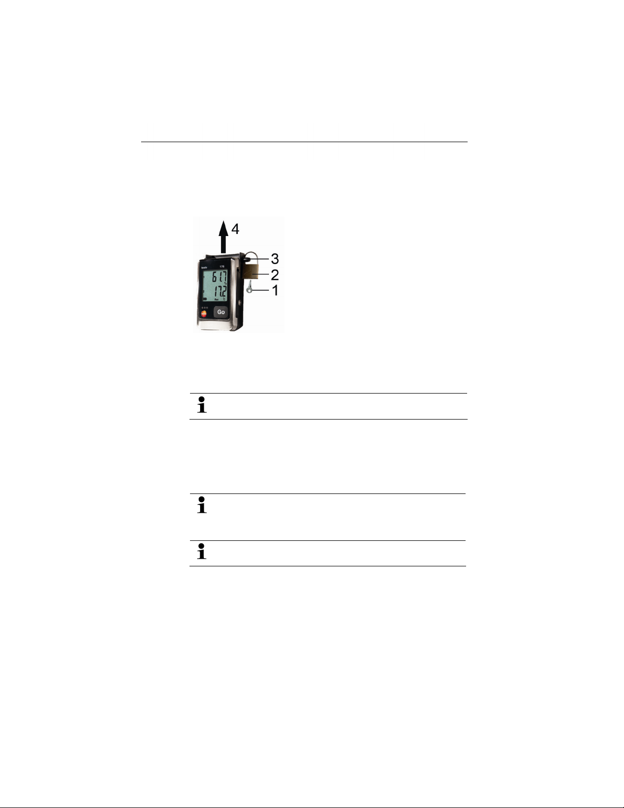
4.1. Unlock the data logger
1. Open the lock with the key (1).
2. Remove the lock (2) from the locking pin.
3. Pull the locking pin (3) out of the holes in the wall bracket.
4. Slide the data logger out of the wall bracket (4).
The data logger is delivered with the battery (type TL-5903)
inserted. The display of the data logger shows rSt.
4 First steps
4.2. Connecting the data logger to PC
For testo Comfort Software Basic 5:
The software is available in the Internet as a free download
43
requiring registration:
The instructions for the installation and operation of the
software can be found in the testo Comfort Software Basic
5 instruction manual, which can be downloaded together
with the software.
The software can be ordered on CD (article-no: 0572
0580), if the download from the Internet is not desired.
For testo Comfort Software Professional und testo Comfort
Software CFR:
> Insert the CD into the CD-ROM drive.
1. Install the software testo Comfort Software.
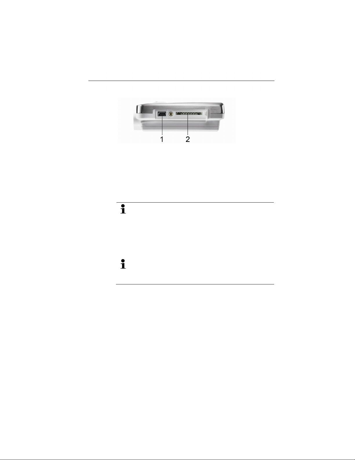
2. Connect the USB cable to a free USB port on the PC.
3. Loosen the screw on the right side of the data logger.
Find Quality Products Online at: [email protected]
www.GlobalTestSupply.com
Page 15
5 Display and control elements
4. Open the cover.
5. Plug the USB cable into the Mini USB port (1).
6. Configure the data logger, see separate operating instructions
testo Comfort Software.
5 Display and control elements
5.1. Display
The data loggers testo 176 T1, testo 176 T3, testo 176 H2
have no display.
The display function can be switched on/off via the testo
Comfort Software.
Depending on the operating status, various information may
be shown in the display. A detailed representation of the
information that can be called up can be found under Menu
overview, page 50.
For technical reasons the display speed of liquid crystal
displays becomes slower at temperatures below 0 °C
(approx. 2 seconds at -10 °C, approx. 6 seconds at -20 °C).
This has no influence on the measuring accuracy.
44
Find Quality Products Online at: [email protected]
www.GlobalTestSupply.com
Page 16
5 Display and control elements
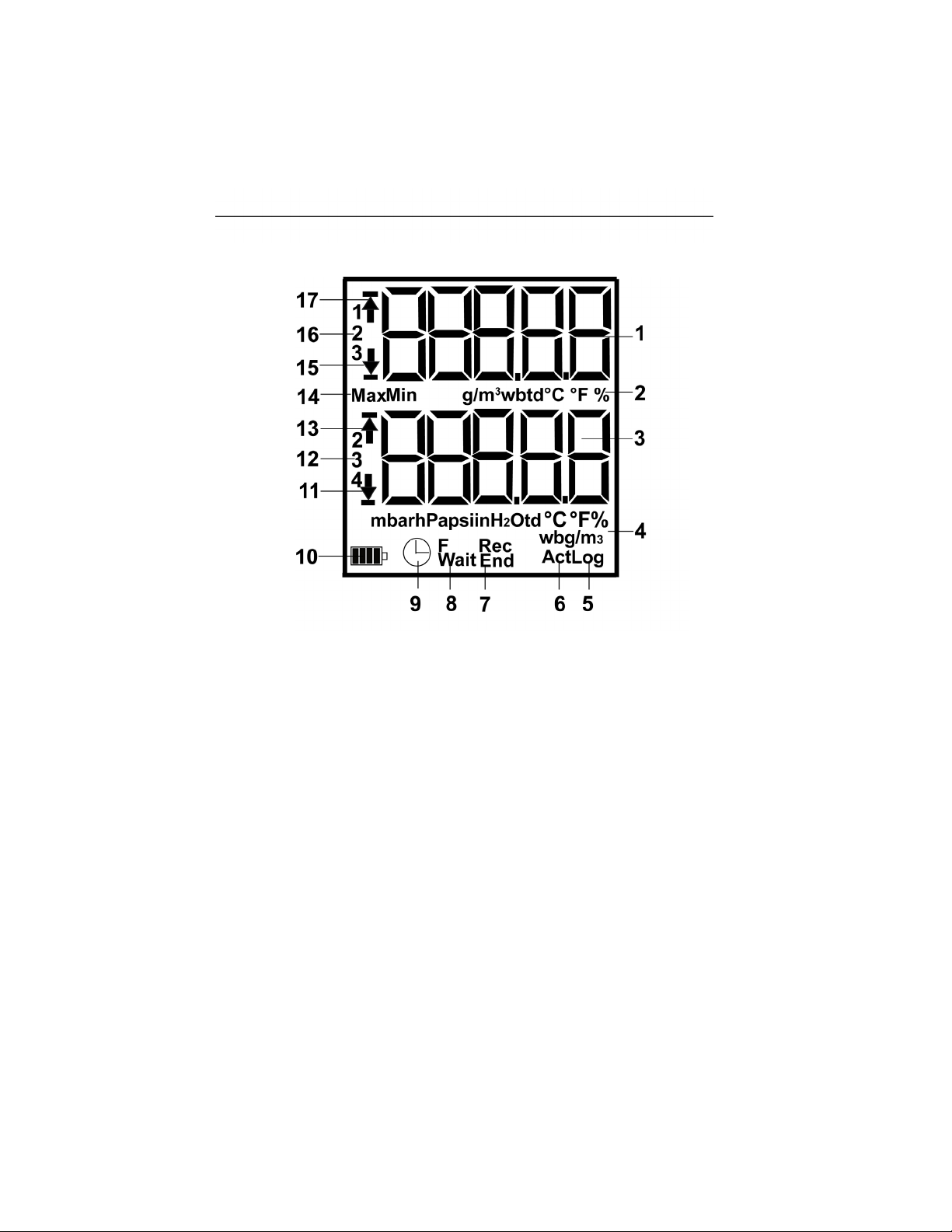
testo 176 T2, testo 176 T4, testo 176 H1, testo 176 P1
1 Measurement value channel 1, 2, 3 (depending on number of
channels and view)
2 Units channel 1, 2, 3 (depending on number of channels and
view)
3 Measurement value channel 2, 3, 4 (depending on number of
channels and view)
4 Units channel 2, 3, 4 (depending on number of channels and
view)
5 Number of saved measurement values with alarm value
violation (Log)
6 Current intermediate measurement value, appears in the
display, but is not saved (Act)
7 End of measuring program (End), measuring program is
running (Rec)
8 Waiting for start of measuring program (Wait), start criterion
Formula programmed (F)
9. Start criterion Date/ Time programmed
45
Find Quality Products Online at: [email protected]
www.GlobalTestSupply.com
Page 17
5 Display and control elements
10 Battery capacity
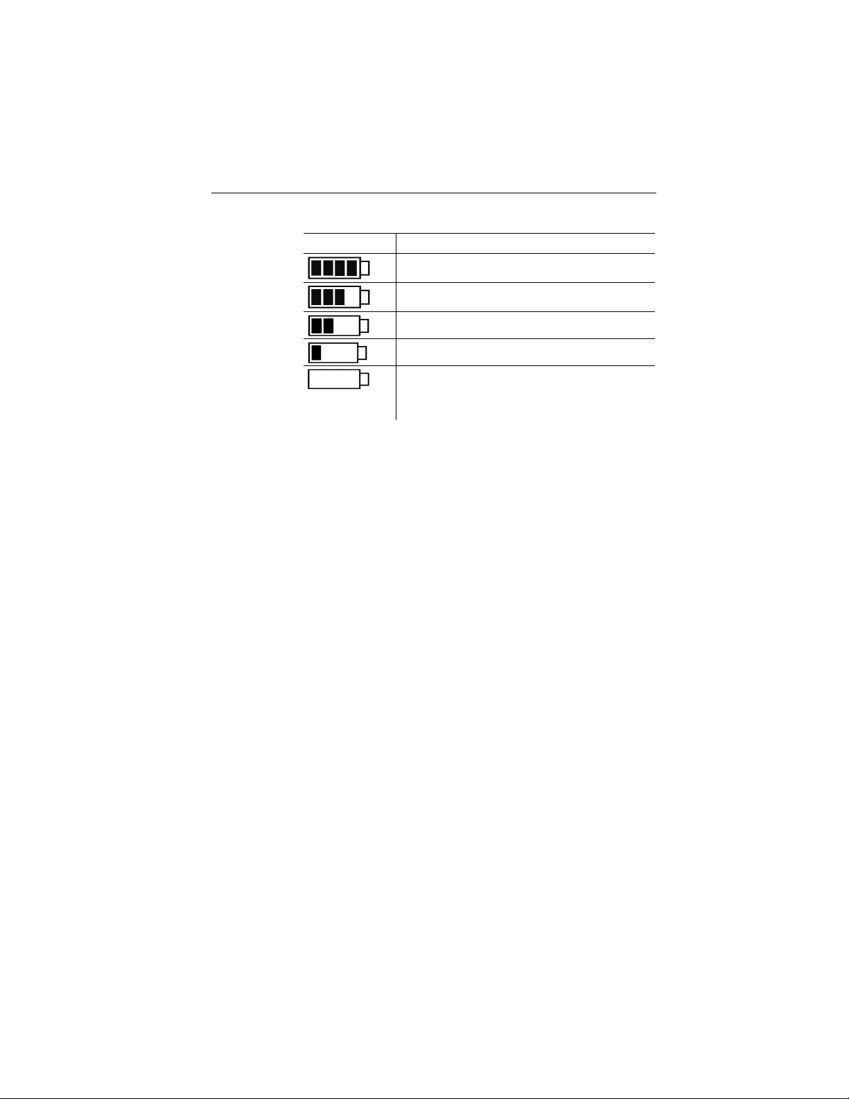
Icon Capacity
11 Lower alarm value displayed channel (2, 3, 4):
• Flashes: programmed alarm value is shown
• Lights: programmed alarm values were fallen short of
12 Channel number (2, 3, 4)
13 Upper alarm value displayed channel (2, 3, 4):
• Flashes: programmed alarm value is shown
• Lights: programmed alarm values were exceeded
14 Identification of measurement value:
Max: highest saved measurement value
Min: lowest saved measurement value
15 Lower alarm value displayed channel (1, 2, 3):
• Flashes: programmed alarm value is shown
• Lights: programmed alarm values were fallen short of
16 Channel number (1, 2, 3)
17 Upper alarm value displayed channel (1, 2, 3):
• Flashes: programmed alarm value is shown
• Lights: programmed alarm values were exceeded
> 151 days
< 150 days
< 90 days
< 60 days
< 30 days
> Read out data and change battery (see
Replacing the battery, page 55).
46
Find Quality Products Online at: [email protected]
www.GlobalTestSupply.com
Page 18

5.2. LED
Representation Explanation
Red LED flashes once
every 10 seconds
Red LED flashes twice
every 10 seconds
Red LED flashes three
times every 10 seconds
Red LED flashes three
times when pressing
the button
Yellow LED flashes
three times
Yellow LED flashes
three times when
pressing the button
Green and yellow LED
flash three times when
pressing the button.
Green LED flashes
three times when
pressing the button
Red, yellow and green
LEDs flash one after
the other
5 Display and control elements
Remaining battery capacity has dropped
below 30 days
Remaining battery capacity has dropped
below 10 days
Battery is empty:
Limiting value exceeded/fallen short of.
Instrument changes from Wait-mode to
Rec-mode.
Instrument is in Rec-mode.
Instrument is in End-mode.
Instrument is in Wait-mode.
Battery was inserted, capacitor in charge
state.
47
Find Quality Products Online at: [email protected]
www.GlobalTestSupply.com
Page 19

5 Display and control elements
5.3. Key functions
A detailed representation of the screen displays can be found
under Menu overview, page 50.
✓ Instrument in operating status Wait and start criterion Button
start programmed.
> Press [GO] for approx. 3 seconds to start the measurement
program.
- The measurement program starts and Rec appears in the
display.
✓ Instrument is in operating status Wait:
> Press [GO], to toggle between the displays of upper alarm
value, lower alarm value, battery lifetime and last measurement
value.
The displays appear in the specified sequence.
✓ Instrument is in operating status Rec or End:
> Press [GO], to toggle between the displays for highest saved
measurement value, lowest saved measurement value, upper
alarm value, lower alarm value, number of times the upper
alarm value has been exceeded, number of times the lower
alarm value has been fallen short of, battery lifetime and last
measurement value.
The displays appear in the specified sequence.
48
Show current measurement value
✓ The last 10 seconds [GO] has not be pressed.
> Press [GO].
- The current measurement value is determined and appears in
the display.
- The display shows Act.
If [GO] is pressed again within the next 10 seconds, the
current measurement value for the next channel will be
determined and displayed.
Find Quality Products Online at: [email protected]
www.GlobalTestSupply.com
Page 20

6 Using the product
6.1. Connecting a sensor
Observe the following points when connecting sensors to data
logger and measuring points.
> Ensure correct polarity of the plugs.
> Press the plugs firmly into the ports to ensure leak tightness.
However, do not apply force!
> Make sure that the plugs are firmly connected to the data logger
or that the connections are closed with blanking plugs.
> Ensure correct positioning of the sensor to avoid disturbing
influences affecting the measurement.
> testo 176 T2, testo 176 T3, testo 176 T4, testo 176 H1, testo
176 H2, testo 176 P1: Make sure that you connect the
configured (with the testo Comfort Software) sensors to the
individual connections. The numbers of the connections are
printed on the housing.
6.2. Programming data logger
In order to adapt the programming of your data logger to your
individual requirements, you require the testo Comfort Software
Basic 5 software. It is available in the Internet as a free download
requiring registration
Service&Support |
The instructions for the installation and operation of the
software can be found in the testo Comfort Software Basic
5 instruction manual that is downloaded together with the
software.
6 Using the product
49
Find Quality Products Online at: [email protected]
www.GlobalTestSupply.com
Page 21

6 Using the product
6.3. Menu overview
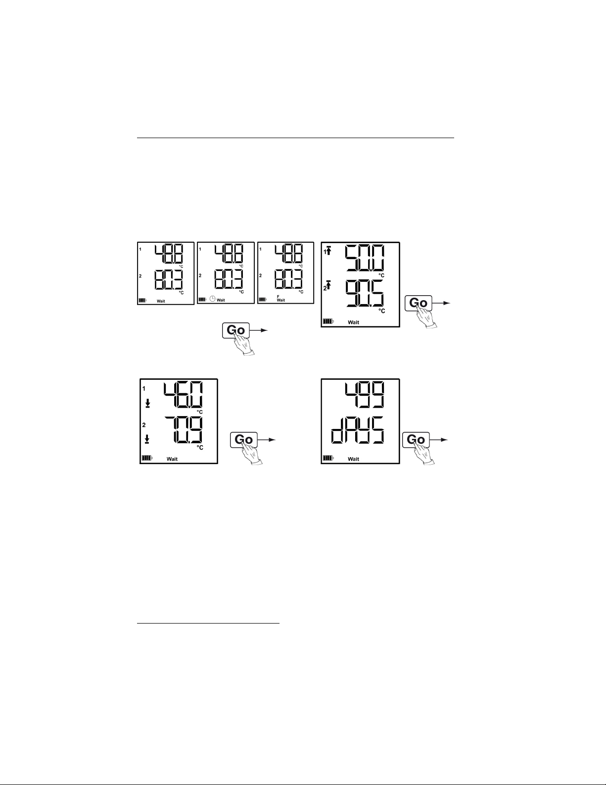
The menu overview shows exemplary display
representations of the data logger testo 176 T2.
The data loggers testo 176 T1, testo 176 T3, testo 176 H2
have no display.
The display must be switched on to be able to show the
corresponding indications. This takes place via the testo
Comfort Software.
The indication in the display is updated according to the
programmed measurement rate. Only readings from active
channels are displayed.
The channels are also activated via the testo Comfort
Software.
The symbols for upper or lower alarm value light up in
operating states Rec and End, if the programmed alarm
value has been exceeded or fallen short off.
After 10 seconds without operating a key the display will
return to its initial state.
50
Find Quality Products Online at: [email protected]
www.GlobalTestSupply.com
Page 22
6 Using the product
Wait-Mode (Wait): Start criterion is programmed, but not yet fulfilled.
6
Start criterion
Date/Time
② Upper alarm value
Start criterion
Formula
① Last
reading
Start criterion key
start / PC start
③ Lower alarm value ④ Battery capacity in days
Last measurement value6 (see Fig. ① Wait mode)
6
Measurement value is not saved
51
Find Quality Products Online at: [email protected]
www.GlobalTestSupply.com
Page 23
6 Using the product
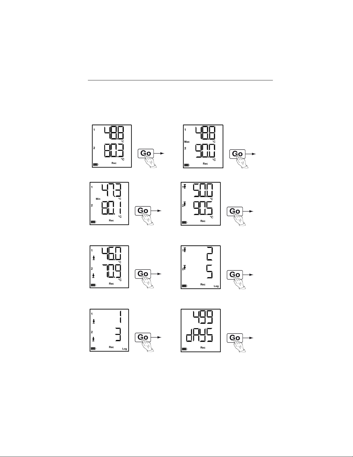
Rec-Mode (Rec): Start criterion was fulfilled, data logger saves readings
End-Mode (End): Measurement program finished (stop criterion reached –
memory full or number of readings) depending on programming
① Last reading ② Highest reading
③ Lowest reading ④ Upper alarm value
⑤ Lower alarm value ⑥ Number of times the upper alarm
value has been exceeded
⑦ Number of times the lower alarm
value has been fallen short of
⑧ Battery capacity in days
Last measurement value (see Fig. ①)
52
Find Quality Products Online at: [email protected]
www.GlobalTestSupply.com
Page 24
6.4. Mounting the wall bracket
The scope of delivery does not include mounting materials
(e.g. screws, wall plugs).
✓ The data logger has been removed from the wall bracket.
1. Position the wall bracket at the desired place.
2. Use a pen or something similar to mark the location for the
fastening screws.
3. Prepare the fastening location in accordance with the fastening
material (e.g. drill hole, insert wall plugs).
6.5. Securing the data logger
4. Fasten the wall bracket with suitable screws.
6 Using the product
✓ The wall bracket has been mounted.
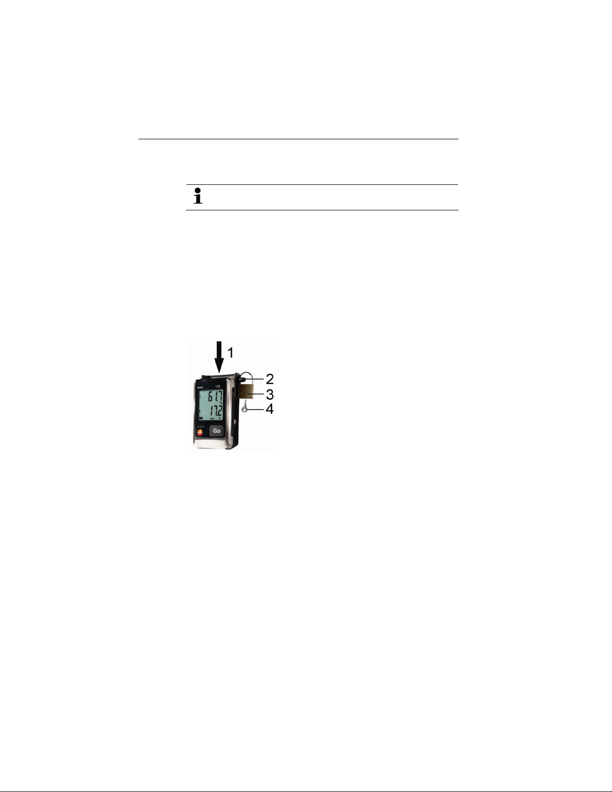
1. Slide the data logger into the wall bracket (1).
2. Push the locking pin (2) through the holes in the wall bracket.
3. Fasten the lock (3) on the locking pin.
4. Pull off the key (4).
6.6. Reading out data
Via USB cable
1. Connect the USB cable to a free USB port on the PC.
2. Loosen the screw on the right side of the data logger.
3. Open the cover.
53
Find Quality Products Online at: [email protected]
www.GlobalTestSupply.com
Page 25
6 Using the product
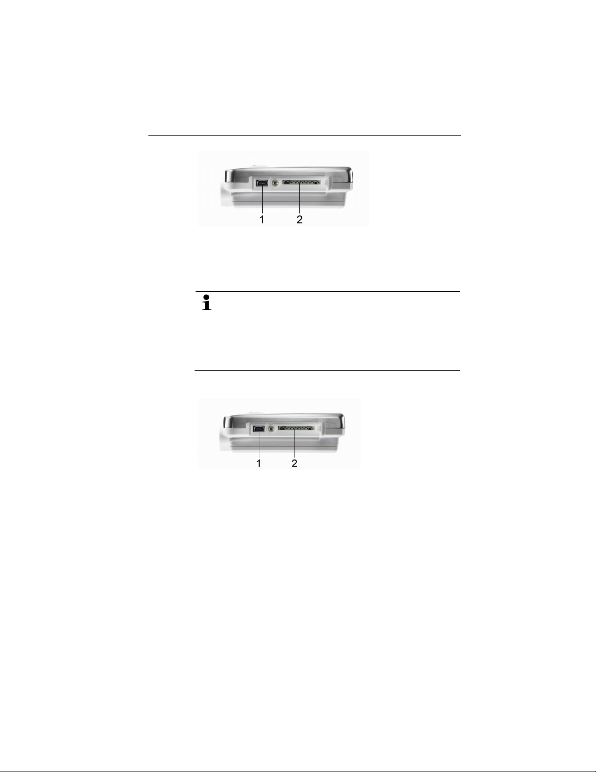
4. Plug the USB cable into the Mini USB port (1).
5. Reading out data logger and processing of read out data, see
separate operating instructions testo Comfort Software.
Via SD card
If a data logger is to be read out in Rec-mode, the data
logger can record measuring data with a maximum
measuring cycle of 10 seconds during the read-out
process.
Once the read-out process has finished, the data logger
can again record measurement data with a measuring cycle
of 1 second, depending on the programming.
1. Loosen the screw on the right side of the data logger.
2. Open the cover.
3. Push the SD card into the SD card slot (2).
- Sd CArd appears in the display.
4. Hold [Go] depressed for longer than 2 seconds.
- COPY appears in the display.
- The yellow LED lights during the copying process.
- The green LED flashes twice and after the copying process the
display shows OUT.
5. Remove the SD card.
6. Insert the SD card into the SD card slot on the PC.
7. Further processing of read out data, see separate operating
instructions testo Comfort Software.
54
Find Quality Products Online at: [email protected]
www.GlobalTestSupply.com
Page 26
7 Maintaining the product
7.1. Replacing the battery
The battery change stops the currently running measuring
program. However, stored measurement data are
preserved.
1. Read out stored measurement data, see Reading out data,
page 53.
✓ If it is no longer possible to read out the saved measurement
data because the battery capacity is too low:
> Change the battery and then read out the stored
measurement data.
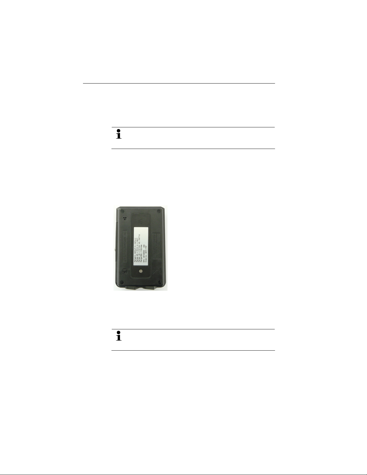
2. Place the data logger on its front.
7 Maintaining the product
3. Loosen the screws on the back of the data logger.
4. Remove the battery compartment cover.
5. Take the empty battery out of the battery compartment.
6. Insert the new battery (type TL-5903). Observe the polarity!
Only use new branded batteries. If a partially exhausted
battery is inserted, the calculation of the battery capacity
will not be performed correctly.
7. Place the battery compartment cover on the battery
compartment.
8. Tighten the screws.
- The display shows rST.
55
Find Quality Products Online at: [email protected]
www.GlobalTestSupply.com
Page 27
7 Maintaining the product
9. Connect the data logger to the PC with a USB cable.
10.Start testo Comfort Software and set up a connection to the
data logger.
11.Reconfigure the data logger or load the old, saved
configuration, see separate operating instructions testo Comfort
Software.
- The data logger is once again ready for use.
The data logger needs to be reconfigured. For this purpose
the software testo Comfort Software must be installed on
the computer and a connection to the data logger must
have been set up.
7.2. Cleaning the instrument
CAUTION
Damage to the sensor!
> Ensure that no liquid enters the inside of the housing.
> If the housing of the instrument is dirty, clean it with a damp
cloth.
Do not use any aggressive cleaning agents or solvents! Weak
household cleaning agents or soap suds can be used.
56
Find Quality Products Online at: [email protected]
www.GlobalTestSupply.com
Page 28

8 Tips and assistance
8.1. Questions and answers
Question Possible causes / solution
FULL appears in the
display, the red LED
flashes twice, out appears
in the display.
Err appears in the display,
the red LED flashes twice,
out appears in the display.
nO dAtA appears in the
display, the red LED
flashes twice.
rST appears in the display. The battery has been inserted. No
H Cap appears in the
display.
- - - -
appears in the display.
Insufficient memory capacity on SD
card to save the data.
> Remove the SD card, free up more
memory space and copy data.
An error occurred while saving data to
the SD card.
> Remove the SD card, free up more
memory space and copy data.
The logger has not yet recorded any
data and is in Wait mode.
> Remove the SD card and wait until
the logger is in Rec mode.
data are recorded.
> Reprogram the data logger via the
software.
The battery has been inserted after
the battery and the auxiliary battery
had been fully discharged. The
auxiliary battery must be charged.
1. Connect the data logger to the PC
with a USB cable.
2. Charge the auxiliary battery
approx. 5-10 minutes via the USBcable.
- The display shows rST.
Sensor of data logger defective or an
incompatible sensor has been plugged
in.
> Contact your dealer or the Testo
Customer Service.
8 Tips and assistance
If you have any questions please contact your local dealer or the
Testo Customer Service. You find contact data on the back of this
document or in the Internet under
57
Find Quality Products Online at: [email protected]
www.GlobalTestSupply.com
Page 29

8 Tips and assistance
8.2. Accessories and spare parts
Description Article no.
Wall bracket (black) with lock 0554 1703
Mini USB cable to connect the data logger
testo 176 to the PC
SD card to read out the data ligger 176 0554 8803
Battery TL-5903 AA-battery 0515 1760
CD testo Comfort Software Basic 5 (if free-of-
charge download from the website with
obligation of registering is not wanted)
CD testo Comfort Software Professional 0554 1704
CD testo Comfort Software CFR 0554 1705
ISO temperature calibration certificate,
calibration points −18 °C, 0 °C, +40 °C; per
channel/instrument
ISO moisture calibration certificate,
calibration points 11,3 %rF; 50,0 %rF; 75,3
%rF at +25 °C/+77 °F; per channel/instrument
ISO calibration certificate absolute pressure,
5 calibration points over the measurement
range
For further accessories and spare parts, please refer to the product
catalogues and brochures or look up unde
0449 0047
0572 0580
0520 0153
0520 0076
0520 0025
58
Find Quality Products Online at: [email protected]
www.GlobalTestSupply.com
 Loading...