

Page 1

Instruction manual en
Fine pressure probe
www. .com
information@itm.com1.800.561.8187
Page 2
General notes
Please read this documentation through carefully and familiarize yourself with the operation of the product before putting it to use. Keep this document to hand so that you
can refer to it when necessary.
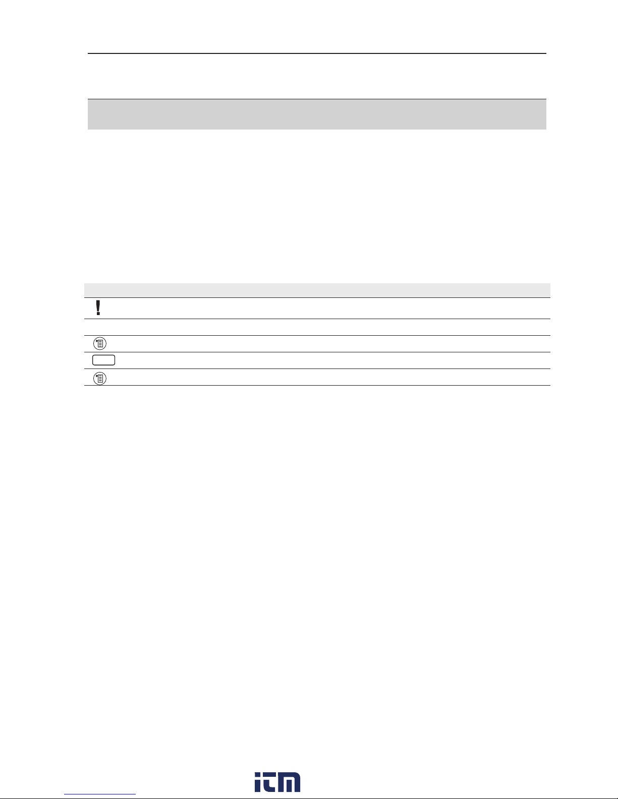
Identifi cation
Icon Significance Comments
Important. Please pay particular attention.
Text Text appears on the instrument display -
Key Press the key.
Function key with the function “OK”. Press function key..
xyz Short form for operating steps.
2
OK
www. .com
information@itm.com1.800.561.8187
Page 3

Contents
General notes ................................................................................................ 2
Contents ........................................................................................................ 3
A. Safety instructions ................................................................................ 4
B. Intended purpose .................................................................................. 5
C Product description .............................................................................. 6
C.1 Overview ....................................................................................... 6
C.2 Use hanger bracket ....................................................................... 7
D. Measurements ....................................................................................... 8
D.1. Measurement with fl ue gas analyzers 0632 3301 - 3305 ............... 8
D.1.1 E-Draught ................................................................................... 8
D.1.2 E-Delta-P ................................................................................... 9
D.2. Measurement with fl ue gas analyzers 0632 3306 - 3307 ............. 10
D.2.1 E-Draught ................................................................................. 10
D.2.2 E-Delta-P Single measurement ................................................. 10
D.2.3 E-Delta-P Program ................................................................... 11
E. Technical data ..................................................................................... 12
F. Accessories/spare parts ..................................................................... 13
3
www. .com
information@itm.com1.800.561.8187
Page 4
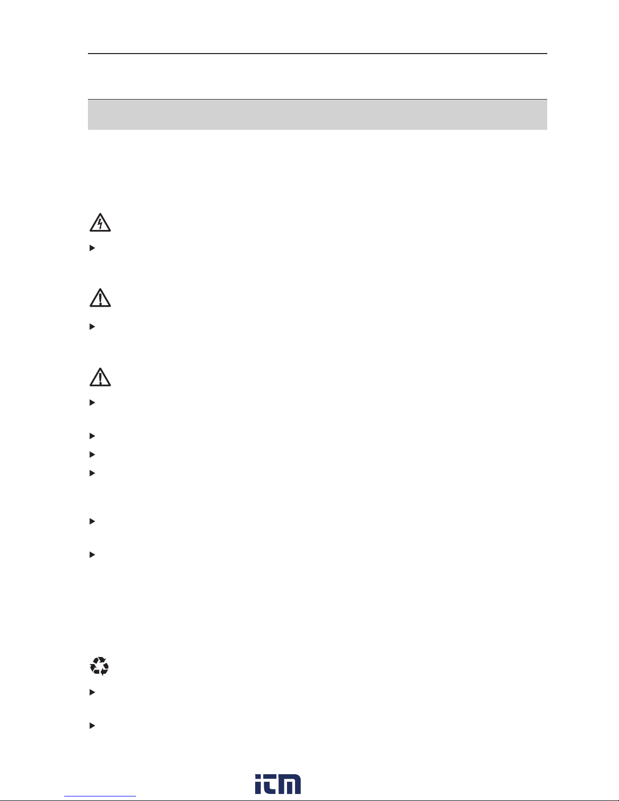
A. Safety instructions
Avoid electrical hazards:
Never use the measuring instrument and fi ne pressure probe to measure on or near
live parts!
Protect the fi ne pressure probe:
Never store the measuring instrument/measuring cells together with solvents
(e.g. acetone). Do not use any desiccants.
Product safety/preserving warranty claims:
Operate the fi ne pressure probe only within the parameters specifi ed in the technical
data.
Handle the fi ne pressure probe properly and according to its intended purpose only.
Never apply force!
Temperatures given on probes/sensors relate only to the measuring range of the
sensors. Do not expose handles and feed lines to any temperatures in excess of
70 °C unless they are expressly permitted for higher temperatures.
Open the measuring instrument only when this is expressly described in the
instruction manual for maintenance purposes.
Carry out only the maintenance and repair work that is described in the Operating
Instructions. Follow the prescribed steps exactly. For safety reasons, use only original
spare parts from Testo.
Any additional work must only be carried out by authorized personnel. Testo will
otherwise refuse to accept responsibility for the proper functioning of the measuring
instrument after repair and for the validity of certifi cations.
Ensure correct disposal:
Dispose of defective rechargeable batteries and spent batteries at the provided
collection points.
Send the measuring instrument directly to us at the end of its useful life. We will
ensure that it is disposed of in an environmentally friendly manner.
4
www. .com
information@itm.com1.800.561.8187
Page 5

B. Intended purpose
This chapter describes the areas of application for which the fi ne pressure probe is
intended.
The fi ne pressure probe can be used for the following measurements in conjunction with
the testo 330 (0632 3301 - 3305 from fi rmware version 1.40 and 0632 3306 - 3307
from fi rmware 1.09):
- Measurement of the fl ue draught for atmospheric gas burners
- Checking the vacuum in a closed room with simultaneous operation of fi replace and
exhaust air equipment
- Measurement of vacuums in equipment rooms for fi replaces
- Parallel Delta-P measurement
The testo Easyheat software (as of software version 2.40) is required for the evaluation
of measurement data.
Under www.testo.com/download-center you can download the current instrument software (Firmware) for the testo 330 (registration required).
5
www. .com
information@itm.com1.800.561.8187
Page 6

C Product description
This chapter provides an overview of the individual components of the product.
C.1 Overview
1 Surface probe connection
2 Measuring instrument connecting cable
3 Capillary hose/pressure tube
connection
4 Hanger bracket
- for hanging on pipes of at least 15 mm
up to max. 40 mm diameter
- for hanging on (plate) edges up to
a thickness of 4 mm
Do not move the brackets sideways
towards the outside. To open, move
the brackets forwards and backwards.
5 Magnetic holder (on rear)
WARNING! Magnetic field!
May be harmful to those with pacemakers.
> Keep a minimum distance of 15 cm between pacemaker and instrument..
ATTENTION! Magnetic field!
Damage to other devices
> Keep a safe distance away from products which could be damaged by the
effects of magnetism (e.g. monitors, computers or credit cards).
6
www. .com
information@itm.com1.800.561.8187
Page 7

C.2 Use hanger bracket
Detach hanger bracket from the rear side of the housing and
fold upwards
To pry open the connecting joint at the opening, carefully
and repeatedly move the hanger brackets in opposite directions.
To open, move the brackets forwards and backwards.
Do not move the hanger brackets sideways towards the
outside.
7
www. .com
information@itm.com1.800.561.8187
Page 8

D. Measurements
A leak test cannot be performed with the fi ne pressure probe.
D.1. Measurement with fl ue gas analy-
zers 0632 3301 - 3305
D.1.1 E-Draught
Connect Pitot tube at input +.
A simultaneous E-Draught and fl ue gas measurement can be performed if:
- the parameter is included in the display sequence.
- no measurement was performed beforehand in the E-Delta-P menu.
Calling up the function:
- Measurements -
OK
- Finepress. probe -
OK
.
Performing the measurement:
1
E-Draught -
OK
- Measurement begins.
2 Stop measuring:
Stop
.
- The reading is recorded.
Option:
To print the reading:
Print
.
3 Copy the reading to the
Draught menu:
OK
.
- The
Measurements menu is opened.
D.1.2 E-Delta-P
The menu is only available if the fi ne pressure probe is connected to the instrument.
A simultaneous E-Delta P and fl ue gas measurement can be performed if:
- the parameter is included in the display sequence.
- no measurement was performed beforehand in the E-Delta-P menu.
8
www. .com
information@itm.com1.800.561.8187
Page 9

Calling up the function:
- Measurements -
OK
- Finepress. probe -
OK
- E-Delta-P -
OK
D.1.2.1 Individual measurement:
Performing the measurement:
1
single -
OK
2 Start measuring:
Start
3 Stop measuring:
Stop
- The reading determined from E-Delta-P is recorded and copied into the Flue gas
menu, where it is displayed (if selected in the Display sequence menu).
D.1.2.2 Logger
Performing the measurement:
1
Logger -
OK
2 Enter the measurement period: Measurement period -
Change
- enter value
(max. 1440 min)
3 Enter rate:
Rate -
Change
- enter value (default value 1 sec)
The measuring rate must not be greater than the measurement period
4 Start measuring:
Start
- The residual time and the current reading are shown.
Options:
Print readings:
Print
.
A printout of all readings is only possible in the “
Memory/location” menu
(
Memory/location -
OK
-
Data
- Print all)
Display readings graphically:
Graph
.
From the graphic display back to the reading display:
Values
5 Stop measuring:
Stop
.
- The determined reading from
E-Delta-P is displayed.
The logger program is always saved, even if it has not run through completely.
9
www. .com
information@itm.com1.800.561.8187
Page 10

D.2. Measurement with fl ue gas analy-
zers 0632 3306 - 3307
D.2.1 E-Draught
Connect Pitot tube at input +.
A simultaneous E-Draught and fl ue gas measurement can be performed if the para-
meter is included in the display sequence.
Calling up the function:
- Measurements -
OK
- Finepress. probe -
OK
- E-Draught -
OK
Carry out measurement:
1 Start measuring:
2 Stop measuring:
Options:
Options
-
Clipboard: Data are saved in the clipboard.
Options
-
Save: The measurement values are saved in a report
Options
-
Show Graphic: The measurement values are saved in a line diagram
3 Exit function:
D.2.2 E-Delta-P Single measurement
A simultaneous E-Delta-P Single measurement and fl ue gas measurement can be
performed if the parameter is included in the display sequence.
Calling up the function:
- Measurements -
OK
- Finepress. probe -
OK
- E-Delta-P Single meas. -
OK
Carry out measurement:
1 Start measuring:
2 Stop measuring:
10
www. .com
information@itm.com1.800.561.8187
Page 11

Options::
Options
-
Clipboard: Data are saved in the clipboard.
Options
-
Save: The measurement values are saved in a report
Options
-
Show Graphic: The measurement values are saved in a line diagram
Options
- Perform measurement
program: The selected measurement program can be
started
3 Exit function:
D.2.3 E-Delta-P Program
Calling up the function:
- Measurements -
OK
- Finepress. probe -
OK
- E-Delta-P Program -
OK
Carry out measurement
1 Start measuring:
- Measurement is automatically ended after the end of the measurement duration
Options
-
Show Graphic: The measurement values are displayed in a line diagram
Optionen
-
Change Program: The measurement duration and measurement rate can
be changed in the selected measurement program
2 Exit function:
11
www. .com
information@itm.com1.800.561.8187
Page 12

E. Technical data
Characteristic Values
Parameter Differential pressure via internal sensor
Temperature via external thermocouple Typ K (accessory)
Calculated variables Flow Display range: 0.15 to 3 m/s
Resolution: 0.1 m/s
Differential pressure Measuring range -9999.9 Pa to 9999.9 Pa
measurement Resolution 0.01 Pa (-149.99 Pa to 149.99 Pa)
0.1 Pa (rest of measuring range)
Accuracy ±0.3 Pa (0 to 9.99 Pa)
±3% of reading (10.00 to 9999.9 Pa)
additionally ±1 digit
Measuring rate max. 1/s
Zero point drift none (cyclical zeroing)
Temperature measurement Measuring range Depends on probe, max. -40 °C to +1200 °C
Resolution 0.1 °C
Accuracy ±0.5 °C (-40 to 100 °C)
± 0.5% of reading (rest of measuring range)
additionally ±1 digit, additionally accuracy of probe
Measuring rate max. 1/s
Temperature measurement Measuring range -200 to 300 °C
with surface probe 0604 0994 Resolution 0.1 °C
(accessory)
Operating temperature 5 to 45 °C
Storage/transport temperature -20 to 50 °C
Humidity 10 to 90% RH non-dewing
Protection class IP 40
Warranty 2 years
12
www. .com
information@itm.com1.800.561.8187
Page 13

F. Accessories/spare parts
Designation Article no.
Fine pressure probe 0638 0330
Flue draught set 0554 3150
Capillary hose set 0554 1215
Update CD (firmware update for testo 330) 0554 3351
testo 330-1 LL 0632 3304
testo 330-2 LL 0632 3305
Basic retrofit kit 0563 3344
Professional retrofit kit 0563 3345
13
www. .com
information@itm.com1.800.561.8187
 Loading...