

Page 1
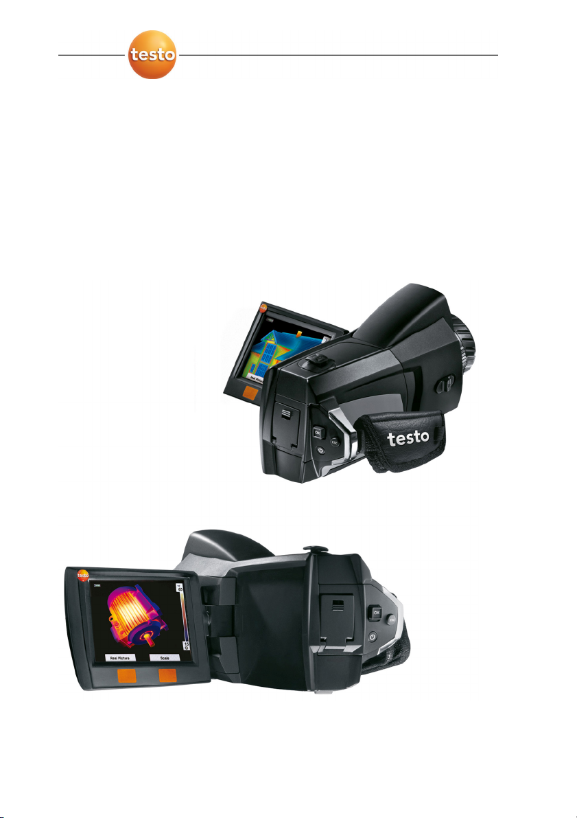
testo 876 · Thermal imager
Instruction manual
www.GlobalTestSupply.com
Page 2

2
www.GlobalTestSupply.com
Page 3

1 Contents
1 Contents
1 Contents ...................................................................................................3
2 Safety and the environment....................................................................4
2.1. About this document........................................................................4
2.2. Ensure safety...................................................................................5
2.3. Protecting the environment..............................................................6
3 Specifications ..........................................................................................7
3.1. Use ..................................................................................................7
3.1. Technical data .................................................................................8
4 Product description...............................................................................12
4.1. Overview........................................................................................12
4.2. Basic properties.............................................................................14
5 First steps ..............................................................................................15
5.1. Commissioning ..............................................................................15
5.2. Getting to know the product...........................................................17
6 Using the product..................................................................................21
6.1. Menu functions ..............................................................................21
6.1.1. Measuring functions.......................................................................................21
6.1.2. Image gallery ................................................................................................. 24
6.1.3. Scale..............................................................................................................25
6.1.4. Display........................................................................................................... 26
6.1.5. Emissivity.......................................................................................................26
6.1.6. Palette ...........................................................................................................29
6.1.7. Configuration .................................................................................................29
6.2. Measuring......................................................................................32
7 Maintaining the product........................................................................35
8 Tips and assistance...............................................................................37
8.1. Questions and answers .................................................................37
8.2. Accessories and spare parts .........................................................38
3
www.GlobalTestSupply.com
Page 4
2 Safety and the environment
2 Safety and the environment
2.1. About this document
Use
> Please read this documentation through carefully and
familiarize yourself with the product before putting it to use. Pay
particular attention to the safety instructions and warning advice
in order to prevent injuries and damage to the products.
> Keep this document to hand so that you can refer to it when
necessary.
> Hand this documentation on to any subsequent users of the
product.
Warnings
Always pay attention to information that is marked by the following
warnings with warning pictograms. Implement the specified
precautionary measures.
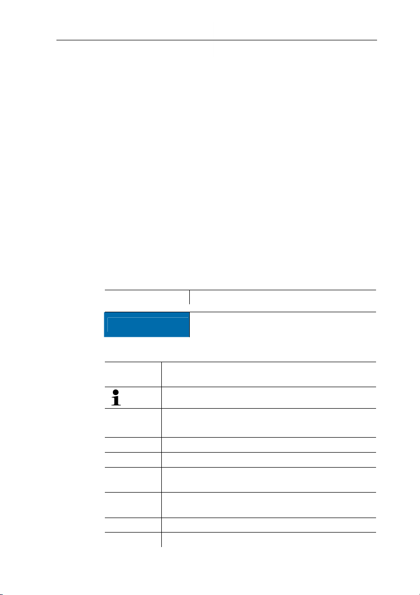
Representation Explanation
CAUTION
indicates circumstances that may lead to
damage to the products
Symbols and writing standards
Represen-
Explanation
tation
Note: Basic or further information.
1. ...
Action: more steps, the sequence must be followed.
2. ...
> ... Action: a step or an optional step.
- ... Result of an action.
Menu Elements of the instrument, the instrument displays
or the program interface.
[OK] Control keys of the instrument or buttons of the
program interface.
... | ... Functions/paths within a menu.
“...” Example entries
4
www.GlobalTestSupply.com
Page 5

2.2. Ensure safety
> Only operate the product properly, for its intended purpose and
within the parameters specified in the technical data. Do not
use any force.
> Do not operate the instrument if there are signs of damage at
the housing, mains unit or feed lines.
The thermal imager must not be directed at the sun or other
sources of intense radiation (e.g. objects with temperatures greater
than 500 °C) during operation. This may lead to serious damage to
the detector. The manufacturer accepts no warranty for this type of
damage to the detector.
> The objects to be measured or the measurement environment
may also pose risks: Note the safety regulations valid in your
area when performing the measurements.
> Do not store the product together with solvents. Do not use any
desiccants.
> Carry out only the maintenance and repair work on this
instrument that is described in the documentation. Follow the
prescribed steps exactly. Use only original spare parts from
Testo.
> Improper use of rechargeable batteries can lead to destruction
or injuries by means of current surges, fire or escaping
chemicals. The following instructions must be observed to avoid
such hazards:
• Only use in accordance with the directions in the instruction
manual.
• Do not short, take apart or modify.
• Do not expose to heavy impacts, water, fire or temperatures
above 60 °C.
• Do not store in the proximity of metal objects.
• Do not use leaky or damaged rechargeable batteries. In the
event of contact with battery acid: Thoroughly wash affected
area with water and consult a doctor, if necessary.
• Only charge in the instrument or the recommended charging
station.
• Immediately stop the charging process if this is not
completed in the given time.
2 Safety and the environment
5
www.GlobalTestSupply.com
Page 6

2 Safety and the environment
• In the event of improper function or signs of overheating,
immediately remove the rechargeable battery from the
measuring instrument/charging station. Caution:
2.3. Protecting the environment
Rechargeable battery may be hot!
> Dispose of faulty rechargeable batteries/spent batteries in
accordance with the valid legal specifications.
> At the end of its useful life, send the product to the separate
collection for electric and electronic devices (observe local
regulations) or return the product to Testo for disposal.
6
www.GlobalTestSupply.com
Page 7

3 Specifications
3.1. Use
The testo 876 is a handy and robust thermal imager. It opens the
door to contactless determination and illustration of the temperature
distribution on surfaces for you.
Typical areas of application are:
• Building inspection: Energetic assessment of buildings,
inspection of heating, ventilation and air conditioning systems.
• Preventative maintenance (servicing): Mechanical and electrical
inspection of systems and machines
• Production monitoring (quality assurance): Monitoring
production processes
Basic properties:
• High-quality wide-angle lens 32° x 23, detector 160 x 120,
manual focus, 2 GB SD card for approx. 1000 images, minimum
focus distance 10 cm, integrated digital camera, dynamic
motorfocus, exchangeable lens, display of surface moisture
distribution
3 Specifications
Export control
Thermal imagers may be subject to the export restrictions of the
European Union.
Please observe the national regulations for export control when
7
exporting.
www.GlobalTestSupply.com
Page 8
3 Specifications
3.2. Technical data
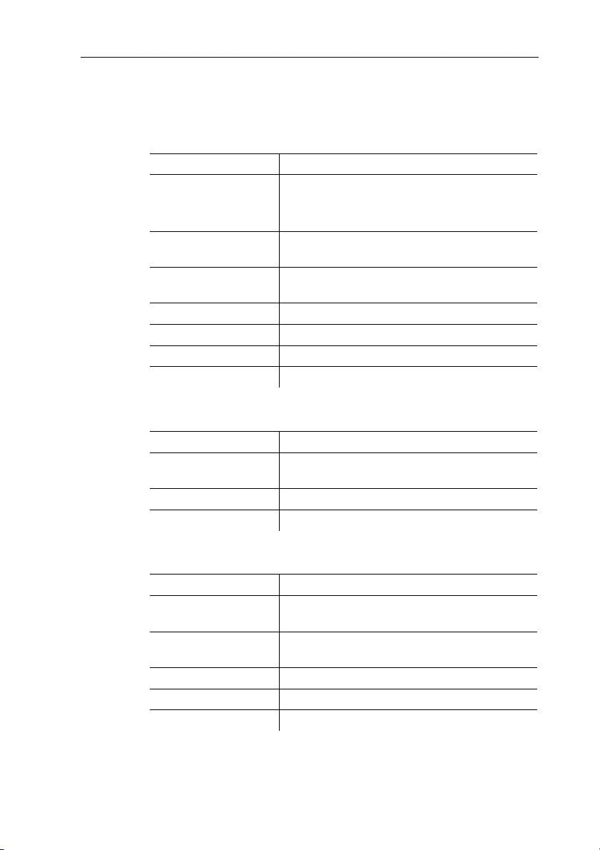
Infrared image output
Characteristic Values
Field of vision/min.
focusing distance
Standard lens: 32° x 23°/0.1 m (0.33 ft)
optional:
9° x 7° / 0.5 m (1.64 ft)
Thermal sensitivity
<80mK at 30°C (86°F)
(NETD)
Geometric resolution
Standard lens: 3.3 mrad
Telephoto lens: 1 mrad
Refresh rate 9Hz
Focus manual + motorized
Detector type FPA 160 x 120 pixels, a.Si
Spectral range 8 - 14 μm
Visual image output
Characteristic Values
Field of vision/min.
33.2° x 25.2° / 0.4m (1.31ft.)
focusing distance
Image size 640 x 480 pixels
Refresh rate 8 to 15 Hz
Image presentation
Characteristic Values
Image display
3.5" LCD with 320 x 240 pixels, Foldable by
90° and rotable by 180°
Display options
Infrared image/real image/infrared and real
image
Video output USB 2.0
Video stream 9 Hz
Colour palettes 4 options
8
www.GlobalTestSupply.com
Page 9
3 Specifications
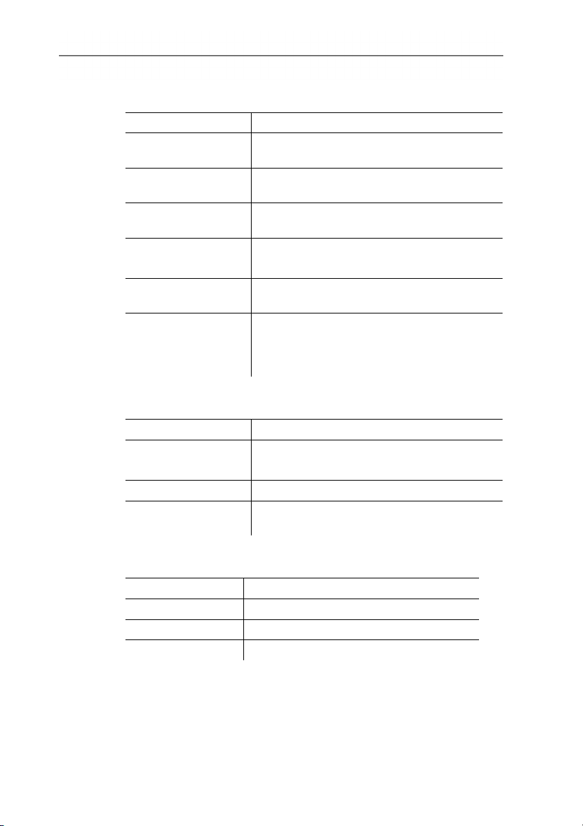
Measuring
Characteristic Values
Temperature range
(can be changed)
Accuracy
-20 - 100 °C/0 - 280°C (-4 - 212 °F/32 536°F)
±2 °C (±3.6 °F) or ±2 % of reading
(whichever is the greater)
Reproducibility
±1 °C (±1.8 °F) or ±1 % (whichever is the
greater)
Measuring point
minimum diameter
On-time (time to
Standard lens: 10 mm at 1 m
Telephoto lens: 3 mm at 1 m
30 s
image)
Measuring functions
Standard measurement (1-point), Cold-/
Hotspot, Display of the surface moisture
distribution via manual entry of the
dewpoint, isotherm, min./max. on area
Image storage
Characteristic Values
File format .bmt
Export options in .bmp, .jpg, .csv
Removable memory SD card
Memory capacity
Scope of delivery: 2 GB (approx. 1000
images)
Lens
Characteristic Values
Standard lens 32° x 23°
Telephoto lens 9° x 7°
Aperture 1.0
9
www.GlobalTestSupply.com
Page 10
3 Specifications
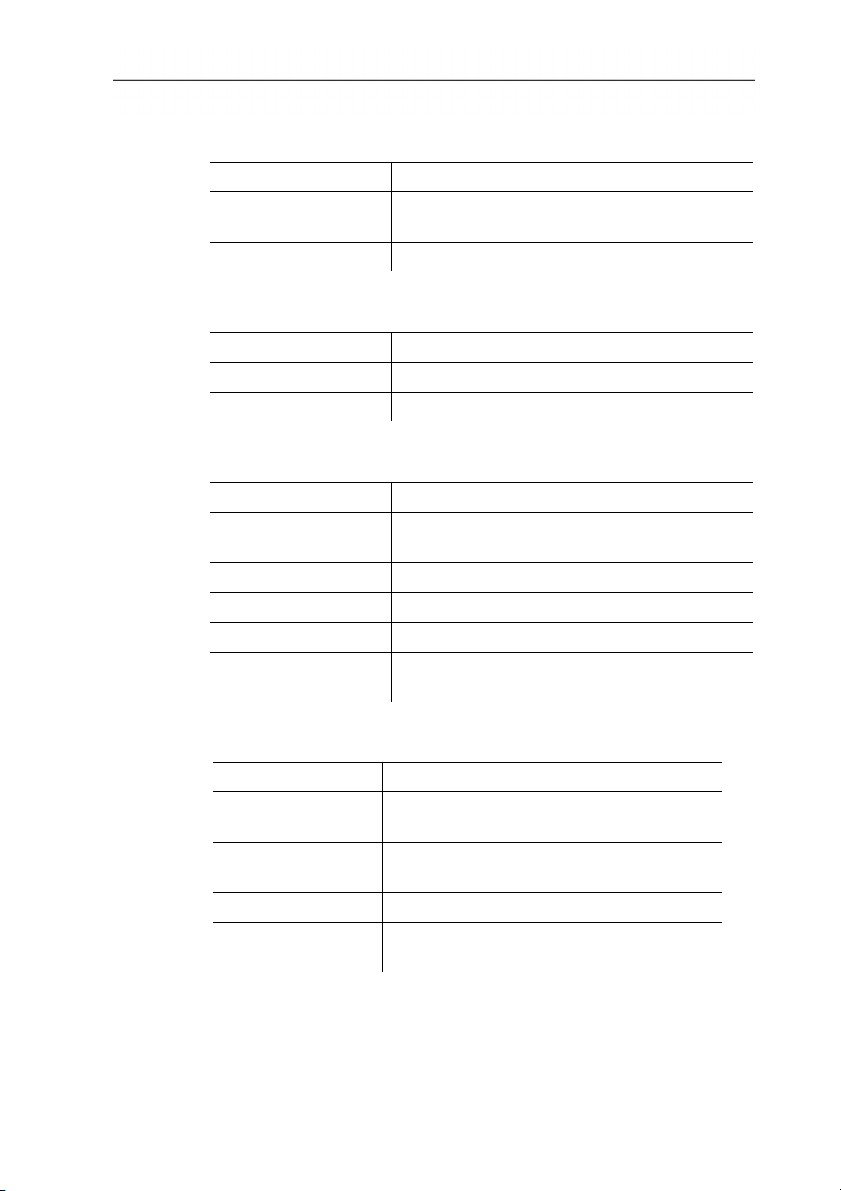
Audio functions
Characteristic Values
Sound
via headset (included in delivery)
recording/playback
Recording period max. 30 s per image
Housing
Feature Values
Housing material ABS and TPE
Housing fronts ABS and PC (nickel plated)
Power supply
Characteristic Values
Battery type
Fast-charging, Li-ion battery can be
changed on-site
Operating time approx. 5 h at 20 - 30 °C (68 - 86 °F)
Charging option In instrument/in charging station (optional)
Mains operation Yes, with mains unit 0554 8808
Mains unit output
5 V/4 A
voltage
10
Ambient conditions
Characteristic Values
Operating
-15 - 40 °C (5 - 113 °F)
temperature
Storage
-30 - 60 °C (-22 - 140 °F)
temperature
Air humidity 20 - 80 %RH, not condensing
Enclosure rating of
the housing
IP54 (Interface terminals closed, battery
connected, lens mounted)
www.GlobalTestSupply.com
Page 11
3 Specifications
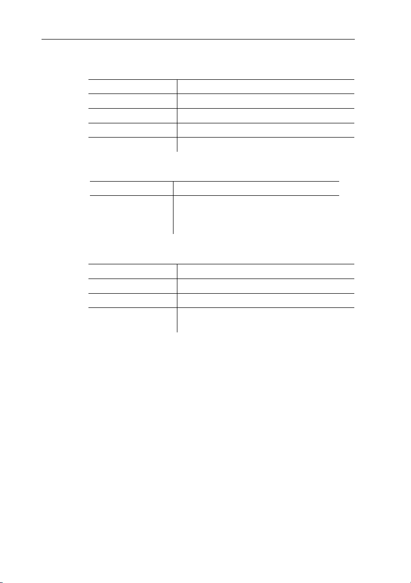
Physical features
Characteristic Values
Weight 900 g (including battery)
Dimensions 210 x 85 x 97mm (8.27 x 3.35 x 3.82")
Tripod mounting Yes, with adapter (included in delivery)
Vibration 2 G
PC software
Characteristic Values
System
requirements
Operating system Windows XP Service
Pack 3, Windows Vista or Windows 7
USB 2.0 interface
Standards, tests, warranty
Characteristic Values
EU Directive 2004/108/EC
Vibration IEC 60068-2-6
Warranty
2 years, warranty conditions: see website
www.testo.com/warranty
11
www.GlobalTestSupply.com
Page 12
4 Product description
4 Product description
4.1. Overview
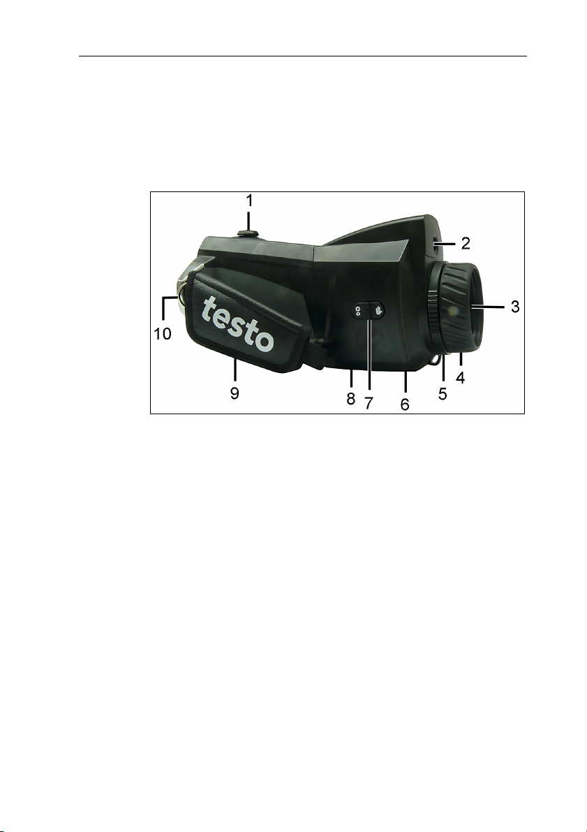
Product components
1 [Motor focus controller]: for motorized focussing.
[Trigger]: for recording (freezing/saving) images.
2 Lens digital camera: to record visual images
3 Lens infrared camera: to record thermographic images.
Exchangeable lens.
4 Rotating ring Manual focussing: for manual focussing.
5 Lens lock ring
6 Metric thread: To fasten a tripod
Do not use table tripods, danger of pipping over!
7 [Motor focus switch]: to switch the motor ficus on/off.
8 Battery compartment with battery shaft, buffer battery shaft,
memory card shaft
9 Wrist strap
10 Fixing ring for carrier belt
12
www.GlobalTestSupply.com
Page 13
4 Product description
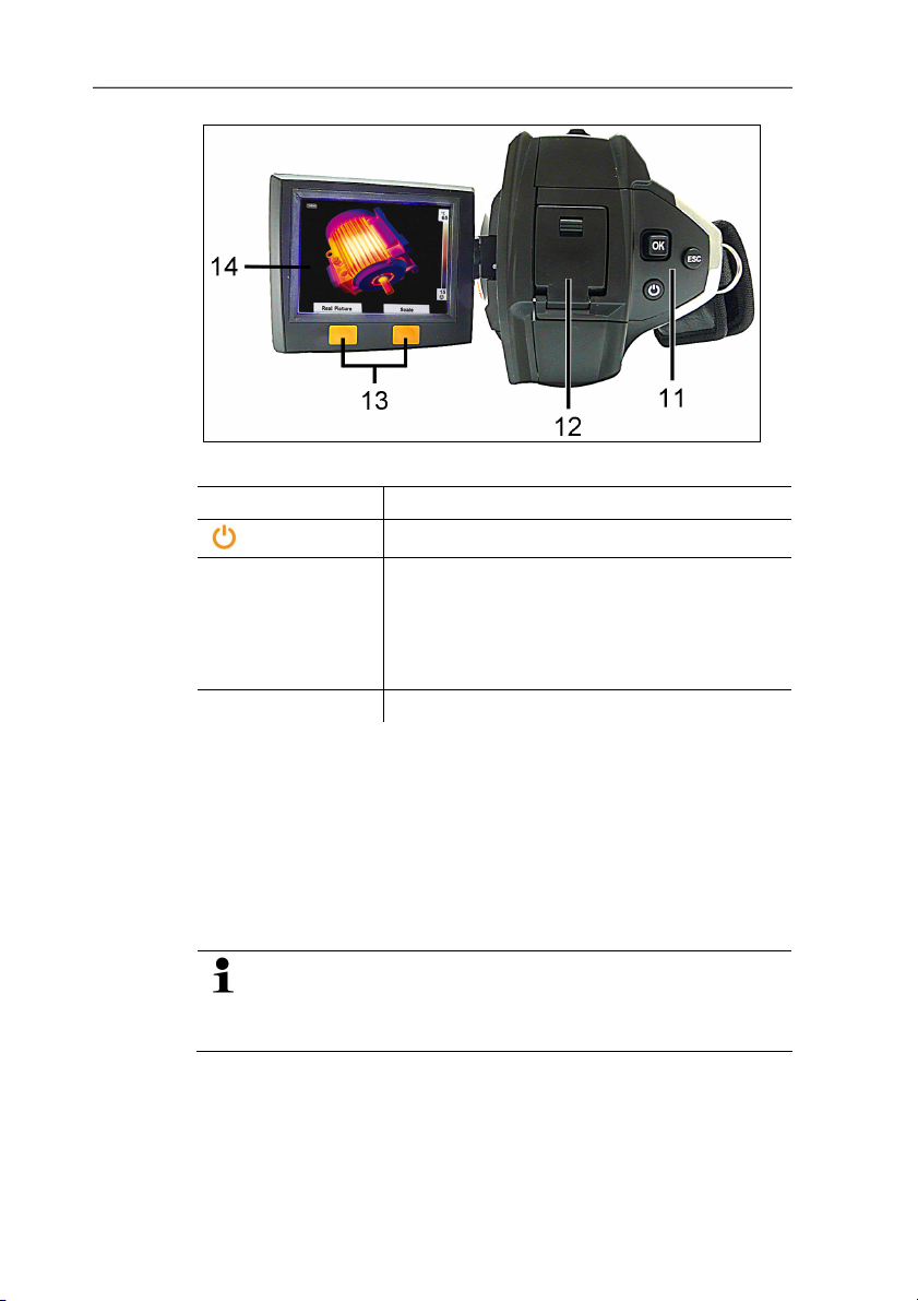
11 Control keys:
Key Functions
[ ]
[OK] and Joystick
Switch the camera on/off
• Press [OK]:
Open menu, confirm selection/setting.
• [OK] move up / down / right / left
= Joystick-function:
Select functions, navigate
[Esc]
Cancel action.
12 Interface terminal USB-interface, mains socket to connect the
supplied mains unit, headset socket, status LED
Status-LED: off (no mains unit connected), flashes (mains unit
connected and rech. batt. is being charged), lights (mains unit
connected and rech. batt. charging completed).
13 Left/right speed dialling key ["xy"]: Call up function. The display
shows which function is assigned to the speed dialling key.
14 Display, foldable by 90° and rotable by 180°
When the camera is switched on, the display remains
active even when folded in. It is recommended to use the
energy saving options to prolong the battery lifetime, see
13
Power-save options…, page 30.
www.GlobalTestSupply.com
Page 14

4 Product description
4.2. Basic properties
Voltage supply
The power is supplied to the instrument via an exchangeable
rechargeable battery or via the included mains unit.
With an attached mains unit, the power is supplied automatically
via the mains unit and the instrument's rechargeable battery is
charged (only at ambient temperatures from 0 to 40 °C).
Under high ambient temperatures a longer charging time
may be required.
Charging the battery is also possible using a desktop charging
station (accessory).
The instrument is equipped with a buffer battery (type CR 1632) to
maintain the system data during an interruption in the power
supply (e.g. when the battery is changed).
File formats and file names
The images are saved according to the following pattern:
XX_YYYYY.ZZZ
XX: IV for infrared image with attached real image, VI for real
image.
YYYYY: 5-digit consecutive number (is reset when resetting to
factory settings, see Factory reset, page 31).
ZZZ (file extension): BMT for infrared image with attached real
image, BMP for real image.
14
www.GlobalTestSupply.com
Page 15
5 First steps
5.1. Commissioning
Contact the rechargeable battery
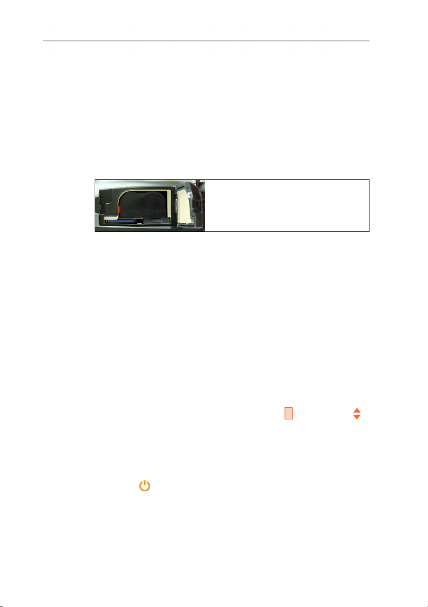
The rech. batt. is included separately and must be inserted.
> Slide the rech. batt. completely into the battery shaft, until it
clicks into place.
-
T
h
e
- The camera starts automatically.
Perform basic settings
> Remove the protective film from the display.
- The start screen appears on the display.
- The Landeseinstellungen (Country settings) dialogue is
opened.
Instrument language (Language) and temperature unit (Unit) can
be set.
1. Move Joystick up/down to select the desired option.
- The selected option has an orange border.
2. Confirm the selection with [OK].
5 First steps
- The selected setting is highlighted orange ( ). The arrows ( )
show that the setting can be changed.
3. Move Joystick up/down to change the setting.
4. Confirm the entry with [OK].
5. Confirm the settings with Übernehmen (Apply).
15
6. Press [ ] to switch off the thermal imager.
www.GlobalTestSupply.com
Page 16
5 First steps
Initial charging of rechargeable battery
The camera is delivered with a partially charged battery.
Completely charge the battery before use.
> Connect the country-specific adapter required for the existing
mains to the mains unit.
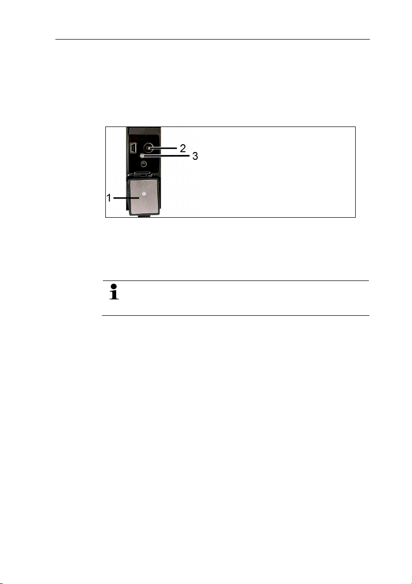
1. Open the cover of the interface terminal on the camera (1).
2. Connect the mains unit to the mains socket (2).
3. Connect the mains plug to a power socket.
- The camera starts automatically.
The rech. batt. can be recharged with the camera switched
on or off. This does by no means influence the time
required to charge the battery.
- Charging of the rech. batt. is started.
- The charge status is indicated by the status LED (3):
• LED flashes: Charging in process.
• LED lights: Battery charged, charging process finished.
4. Charge the rech. batt. completely, then disconnect the device
from the mains unit.
- After initial charging of the rech. batt. the camera is ready for
use.
Charging the battery is also possible using a desktop charging
station (accessory).
16
www.GlobalTestSupply.com
Page 17
5.2. Getting to know the product
Adjusting the hand strap
1. Open the velcro fastening.
2. Loosen the strap.
3. Match the hand strap by loosening or fastening the strap.
5 First steps
Insert the memory card
SDHC-cards (SD High Capacity) are not supported.
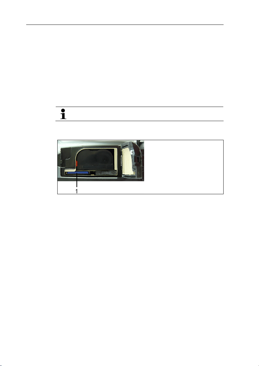
1. Open the rech. batt. cover on the underside of the camera.
2. Push the memory card (SD-card) into the card slot (1).
> To remove the memory card: Press on the memory card to
release the lock.
Mount/remove infrared protection glass
Installation:
1. Attach the protection glass fastened to the red mounting ring to
the lens and turn the mounting ring clockwise to the stop.
2. Remove the red mounting ring from the protection glass.
Removal:
1. Attach the red mounting ring to the protection glass.
2. Turn the mounting ring anticlockwise and remove the protection
glass.
After mounting/removing the protection glass, activate or deactivate
the Protection glass option, Optics... page 30. If this option is set
incorrectly, the stated measuring accuracy is not guaranteed.
17
www.GlobalTestSupply.com
Page 18
5 First steps
Changing lens
Only lenses that were adjusted to the respective thermal imager
can be used. The serial number on the lens must match the serial
number of the instrument, see Optics... page 30.
> Switch instrument off before changing the lens.
> To keep the lens from falling out: Hold the instrument with the
lens pointing up.
1. Turn lens lock ring anticlockwise to the stop (approx. 2 cm).
2. Remove lens.
3. Insert the new lens, thereby take care to align the white
markings on lens and instrument to each other.
4. Turn the lens lock ring clockwise to the stop.
Always store lenses not in use in the container designed for this in
the case.
> Turn the lens ring clockwise to the stop, place the lens in the
container and close it.
Switch the imager on/off
1. Remove protection cap from the lens.
2. Press [
].
- The start screen appears on the display. The type designation
of the imager and the firmware version are shown.
- The measurement view is opened after the warm-up period.
- The imager performs an automatic zeroing approx. every 60
sec. This can be recognized by means of a "click". The image is
frozen briefly when this occurs.
> To switch off: Press [ ].
- The display goes out and the imager is switched off.
18
Manually focusing the image
> Turn Rotating ring of the lens until the image is in focus.
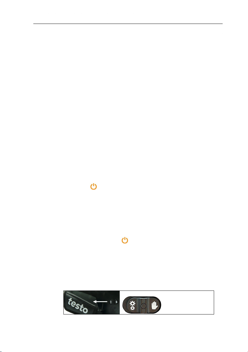
Focussing with the motor focus
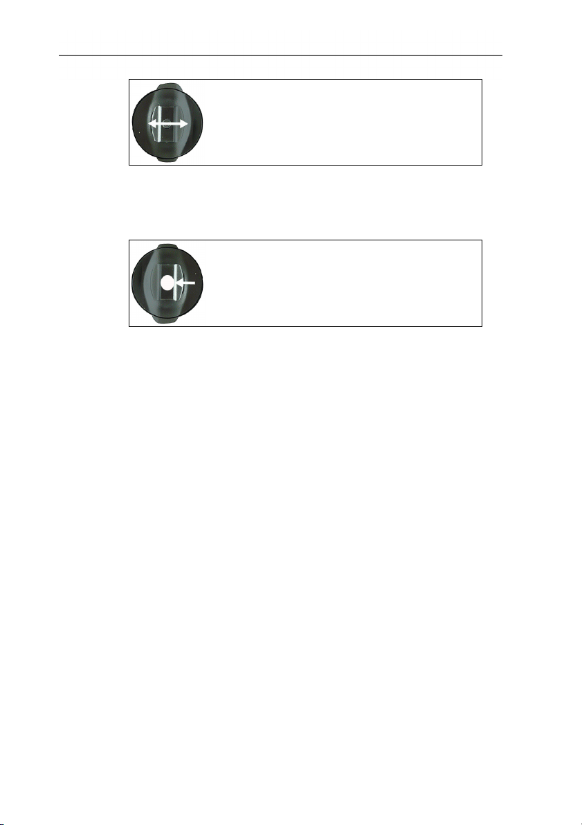
> Slide the [Motor focus switch] towards the hand strap.
www.GlobalTestSupply.com
Page 19
5 First steps
> Move the [Motor focus controller], until the image is correctly
focussed.
Recording (freeze/save) an image
> Press [Trigger].
- The image is frozen (still).
If the image is to be saved, press the speed selection key [Folder]
to set the desired memory location, see Create new folder, page
24.
• The IR-image or the IR-/real image is displayed. Infrared image
is saved, real image is saved in the same file as an attachment
to the infrared image.
• Real image is shown: Real image is saved.
> Save image: Press [Trigger] once again, alternatively: Press
[OK].
or
discard the image: Press [ESC].
Getting to know the quick select buttons
The quick select buttons can be assigned functions that are
required often so that you can call them up directly.
Factory settings:
• Left quick select button: [Scale].
• Right quick select button: [Image type].
19
www.GlobalTestSupply.com
Page 20

5 First steps
Changing assignment of the quick select buttons
1. Move Joystick left or right to open the Configure key function
list for the left or right quick select button.
2. Move Joystick up/down to select the desired function.
Function Description
Image type Change display mode: Infrared image, real
image or infrared/real image.
1
Palette Change colour palette for the infrared
image.
Emissivity...
Scale...
Adjustment
Set emissivity and reflected temperature.
Set scale limits.
Perform manual zero point calibration.
3. Press [OK] to activate the selected function.
Navigating in the menu
1. Press [OK] button.
- The Menu is opened.
2. Select navigation/function:
• Move Joystick up or down to select the menu item.
• Press [OK] to confirm the selection. Or for menu items that
are marked with an arrow (►): Move Joystick to the right.
• Move Joystick to the left to return to the previous menu
level.
• Press [OK] to select the function.
• Press [ESC] to cancel the process and change to
Measuring Mode.
- Depending on the selected menu item, press [OK] to perform a
setting or open a submenu/dialogue, see Menu functions, page
21.
1
Real image and infrared lens have a different angle of view due to the spacial
separation. The image areas therefore do not correspond completely (parallax
error).
20
www.GlobalTestSupply.com
Page 21

6 Using the product
6.1. Menu functions
6.1.1. Measuring functions
1-point measurement
The 1-point measurement is the standard measuring function. If
this is activated ( ), all available options can be selected via the
quick select buttons.
> [OK] | Measurement | [OK] | 1-point measurement | [OK].
If the 1-point measurement is activated, the crosshairs can be
moved using the Joystick on frozen and saved images to read off
the individual temperatures.
With saved images, the 1-point measurement must be activated
via the menu for the respective opened picture.
Cold-/Hotspot
Cold-/Hotspot shows the minimum and maximum temperature
point on the display. If Cold-/Hotspot is activated (
select buttons with the Coldspot and Hotspot functions can be
permanently assigned and can no longer be changed.
With frozen images, the crosshairs can be moved and the
min./max. point is visible. The min./max. point is not saved.
With saved images, Cold-/Hotspot must be activated for the
respective opened image.
> [OK] | Measurement | Cold-/Hotspot | [OK].
> Select left or right Coldspot or Hotspot quick select button to
activate/deactivate the respective function.
6 Using the product
), the quick
Min./Max. on area
Min./Max. on area shows the minimum and maximum temperature
value within the area selection shown on the display. The area
selection is neither scalable nor adjustable. If Min./Max. on area is
activated (
), the quick select buttons with the Scale... and
Emissivity... functions can be permanently assigned and can no
longer be changed.
With frozen images, the crosshairs can be moved. The Min./Max.
on area values are saved together with every image.
21
www.GlobalTestSupply.com
Page 22
6 Using the product
With saved images, Min./Max on area must be activated for the
respective opened image.
> [OK] | Measurement | Min./Max. on area | [OK].
Isotherm
Isotherm shows temperatures in a selectable temperature range in
a uniform colour. If Isotherm is activated (
buttons with the Isotherm and Emissivity... functions can be
permanently assigned and can no longer be changed.
With frozen images, the crosshairs can be moved.
> [OK] | Measurement | Isotherm | [OK].
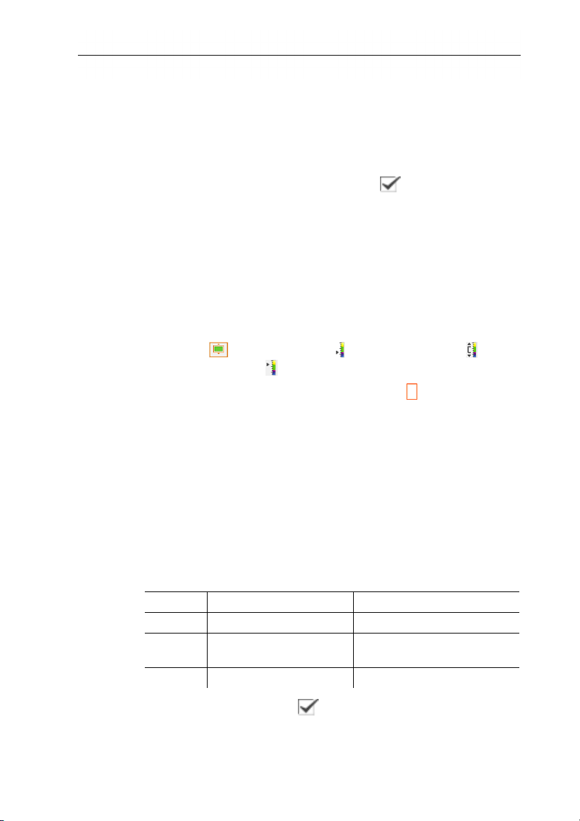
To set the isotherm colour and range:
1. [Isotherm]
- The Isotherm dialogue is opened.
2. Move Joystick left/right to select the desired option: Isotherm
colour (
), lower limit value ( ), temperature range ( ) or
upper limit value ( ).
), the quick select
22
- The selected option has an orange border (
).
3. Move Joystick up/down to change the colour or the value(s).
- Changes are applied immediately so that the effects on the
display of the infrared image can be checked directly.
4. Close dialogue with [OK] or [Esc].
- The changes are saved.
Moisture
The surface humidity is calculated using the manually entered
dewpoint temperature and the measured surface temperatures. In
the display, the areas that are at risk of developing mould are
shown using a special colour palette:
Colour Surface moisture Assessment
green 0 - 64 % noncritical
yellow-
65 - 80 % potentially critical
orange
red >80 % critical
If this function is activated ( ), the quick select buttons are
permanently assigned the Dewpoint and Emissivity... functions.
www.GlobalTestSupply.com
Page 23

6 Using the product
At the upper edge of the display, the relative air humidity, air
temperature and dewpoint temperature are shown.
1. [OK] | Measurement | [OK] | Humidity | [OK].
- The Dewpoint dialogue is opened. The dewpoint temperature
can be entered.
If the image is to be evaluated using the IRSoft software,
the values for the ambient temperature and ambient
humidity must be entered. If these values are missing, the
image cannot be evaluated with the software!
2. Move Joystick up/down to select the desired option.
- The selected option has an orange border.
3. Confirm the selection with [OK].
- The selected number is highlighted orange.
4. Move Joystick up/down to set the desired value. Move
Joystick right/left to change between the numbers.
5. Confirm the entry with [OK].
6. Confirm the settings with Apply.
Measuring range
The measuring range can be set to adapt to the respective area of
application.
1. [OK] | Measurement | [OK] | Measurement range.
2. Select the desired temperature range and confirm with [OK].
Depending on the scene temperature, the measuring range
may be undershot or exceeded. In this case, --- or +++ is
shown instead of the readings.
> If this occurs, change the measuring range.
23
www.GlobalTestSupply.com
Page 24

6 Using the product
6.1.2. Image gallery
Show images…
1. [OK] | Image gallery | [OK] | Show images… | [OK].
- The Folder dialogue is opened.
- The folder name of the opened folder is displayed in the header.
ROOT designates the base folder (top level).
- The saved data is shown as preview images (image overview).
The image saved last is shown directly behind the folders.
Optional:
> Press the right [Page scroll] quick select button to change to
page scroll.
In page scroll, you can navigate in groups of 3 x 3
images/folders (page by page). To select/open an image/folder,
you must change back into Single Image.
2. Navigate:
• In page scroll: Move Joystick up/down to change between
the pages.
• In single image: Move Joystick up/down/left/right to select a
preview image/a folder (orange border).
• Open selected folder with [OK].
3. In single image: Press [OK] to open selected preview image.
Press Gallery to return to the image overview.
24
Delete image
1. In single image: Select image (orange border) or select and
open image.
2. Press Delete to delete the selected or open image.
- A confirmation request appears as to whether the image should
really be deleted.
3. Confirm with [OK] or cancel process with [Esc].
Create new folder
1. In the Folder dialogue: Select New Folder with the joystick and
confirm with[OK].
- The Folder name dialogue is opened.
www.GlobalTestSupply.com
Page 25

2. Name folders: Use the Joystick to select the desired letters
and confirm with[OK].
The folder name can consist of up to 8 characters.
Incorrect entries can be deleted using the right [◄C] quick select
button.
3. Press left [Create Folder] quick select button to create the
folder.
Erase all
1. [OK] | Image gallery | [OK] | Erase all… | [OK].
- A confirmation request appears as to whether all files on the
memory card should be deleted. Folders are not deleted.
2. Confirm erase with [OK] or cancel process with [Esc].
6.1.3. Scale...
Set scale limits
You can choose between auto-scaling (continuous, automatic
adjustment to the current min./max. values) and manual scaling.
The scale limits can be set within the activated measuring range
(see Measuring range page 23). All temperatures that undershoot
or exceed the limit value are shown in the colour of the limit value
(depending on the selected colour palette, see Palette page 29).
Temperature ranges that are not relevant can thus be hidden.
1. [OK] | Scale… | [OK].
- The Set scale dialogue is opened.
2. Move Joystick left/right to select the desired option: Auto-
scaling (
value (
6 Using the product
), min. value ( ), temperature range ( ) or max.
)
- The selected option has an orange border ( ).
3. With the selection of min. value, temperature range or max.
value: Move Joystick up/down to change the value(s).
- Changes are applied immediately so that the effects on the
display of the infrared image can be checked directly.
4. Close dialogue with [OK] or [Esc].
- The changes are saved.
25
www.GlobalTestSupply.com
Page 26

6 Using the product
6.1.4. Display...
Select display options
The presentation can be adapted by means of showing/hiding the
following elements: Crosshairs, temperature scale and quick select
buttons.
Hidden function keys can be shown again by pressing a quick
select button: The first press of the button shows the function keys
again. To trigger a function, the button must be pressed again.
1. [OK] | Display… | [OK].
- The Display options dialogue is opened.
2. Move Joystick up/down to select the desired option.
- The selected option has an orange border (
3. Activate (
4. Confirm settings with the [Apply] quick select button.
or
Discard settings with [Esc].
6.1.5. Emissivity...
Emissivity
The emissivity describes the capability of a body to emit
electromagnetic radiation. This is material-specific and must be
adapted for correct measurement results.
Non-metals (paper, ceramic, gypsum, wood, paints and coatings),
plastics and food have high emissivity, which means that the
surface temperature can be easily measured using infrared.
Because of their low or non-uniform emissivity, bright metals and
metal oxides are only somewhat suited for infrared measurement.
You must anticipate highly inaccurate measurements. A remedy for
this is coatings that increase the emissivity, e.g. paint or emission
adhesive (art. no. 0554 0051) which must be applied to the object
being measured.
The following table gives typical emissivities of important materials.
These values can be used as orientation with the user-defined
settings.
).
) or deactivate ( ) option with [OK].
26
www.GlobalTestSupply.com
Page 27

6 Using the product
Material (material temperature) Emissivity
Aluminium, bright rolled (170 °C) 0.04
Cotton (20 °C) 0.77
Concrete (25 °C) 0.93
Ice, smooth (0 °C) 0.97
Iron, emery ground (20 °C) 0.24
Iron with casting skin (100 °C) 0.80
Iron with rolling skin (20 °C) 0.77
Gypsum (20 °C) 0.90
Glass (90 °C) 0.94
Rubber, hard (23 °C) 0.94
Rubber, soft grey (23 °C) 0.89
Wood (70 °C) 0.94
Cork (20) 0.70
Radiator, black anodised (50 °C) 0.98
Copper, slightly tarnished (20 °C) 0.04
Copper, oxidized (130°C) 0.76
Plastics: PE, PP, PVC (20 °C) 0.94
Brass, oxidized (200°C) 0.61
Paper (20 °C) 0.97
Porcelain (20 °C) 0.92
Black paint, matt (80 °C) 0.97
Steel, heat-treated surface (200 °C) 0.52
Steel, oxidized (200) 0.79
Clay, burnt (70 °C) 0.91
Transformer paint (70 °C) 0.94
Brick, mortar, plaster (20 °C) 0.93
27
www.GlobalTestSupply.com
Page 28

6 Using the product
Reflected temperature
Using this offset factor, the reflection is calculated out due to the
low emissivity and the accuracy of the temperature measurement
with infrared instruments is improved. In most cases, the reflected
temperature is identical to the ambient air temperature. Only when
objects with strong emissions with much higher temperatures (such
as ovens or machines) are in the proximity of the object being
measured should the radiation temperature of theses heat sources
be determined and used (e.g. using a globe thermometer). The
reflected temperature has only little effect on objects with high
emissivity.
Set emissivity/reflected temperature
You can choose between a user-defined emissivity and 8 materials
with recorded emissivities.
The reflected temperature can be set individually.
1. [OK] | Emissivity… | [OK].
- The Emissivity dialogue is opened.
2. Move Joystick up/down to select the desired material.
The designation of the materials in the selection list is
configured during commissioning of the thermal imager in
the language selected by the user. A translation does not
occur in the event of subsequent changeover of the
language in the instrument.
Using the PC software, other materials can be imported into
the instrument from an existing list. The language for the
materials here depends on the operating system language
of the PC.
28
- The selected material is highlighted orange ( ). The
corresponding emissivity is shown to the right next to the
material.
3. Move Joystick to the right to switch to the setting of the
emissivity (only available when selecting User defined) or to
Reflected temp..
- The selected option has an orange border ( ).
4. Confirm the selection with [OK].
- The selected number is highlighted orange ( ).
5. Move Joystick up/down to set the desired value. Move
Joystick right/left to change between the numbers.
6. Confirm the entry with [OK].
www.GlobalTestSupply.com
Page 29

7. Confirm the settings with Apply.
- The changes are saved.
- The selected emissivity (
display in measurement view.
6.1.6. Palette
Change colour palette for the infrared image
You can choose between 4 existing palettes. The currently
activated option is marked with a tick ( ).
1. [OK] | Palette| [OK].
2. Move Joystick up/down to select the desired option.
3. Confirm the selection with [OK].
6.1.7. Configuration
Time/date...
Time and date can be set. Time and date format are automatically
set based on the selected instrument language.
1. [OK] | Configuration… | [OK] | Time/date… | [OK].
- The Set time/date dialogue is opened.
2. Move Joystick up/down to select the desired option.
6 Using the product
) is shown at the bottom right in the
- The selected option has an orange border (
).
3. Confirm the selection with [OK].
- The selected number is highlighted orange (
).
4. Move Joystick up/down to set the value. Move Joystick
right/left to change between the numbers.
5. Confirm the entry with [OK].
6. Confirm the settings with Apply.
Country settings…
Instrument language and temperature unit can be set.
1. [OK] | Configuration… | [OK].| Country settings… | [OK].
- The Country settings dialogue is opened.
2. Move Joystick up/down to select the desired option.
- The selected option has an orange border (
29
).
www.GlobalTestSupply.com
Page 30

6 Using the product
3. Confirm the selection with [OK].
- The selected setting is highlighted orange ( ).
4. Move Joystick up/down to change the setting.
5. Confirm the entry with [OK].
6. Confirm the settings with Apply.
Optics...
The lenses adjusted to the instrument are shown. Only the lenses
that are shown may be used.
The high-temperature filter registered in the instrument is shown.
With use of another high-temperature filter, the specified accuracy
is not ensured.
> [OK] | Configuration… | [OK] | Optics… | [OK].
Using the Protection glass option, you can set whether an infrared
protection glass is used or not. Ensure the correct setting to
prevent corruption of the measurement results.
> Press [OK] to activate (
glass option.
- With the option activated, the protection glass symbol ( ) is
shown in the bottom right of the display.
Power-save options…
Options can be set to extend the rechargeable battery running time.
1. [OK] | Configuration… | [OK] | Power-save options… | [OK].
- The Power-save options dialogue is opened.
2. Move Joystick up/down to select the desired option.
- The selected option has an orange border (
3. Confirm the selection with [OK].
- LCD backlight: The selected setting is highlighted orange and
can be changed (
> Move Joystick up/down to change the setting. Confirm the
entry with [OK].
- Switch off LCD or Power off imager: The selected option can
be activated or deactivated.
).
) or deactivate ( ) the Protection
).
30
www.GlobalTestSupply.com
Page 31

6 Using the product
> Press [OK] to activate (
) or deactivate ( ) the function.
- With the option activated, the length of time until shut-down
can be set.
> Move Joystick to the right and press [OK]. Move Joystick
up/down to change the setting. Confirm the entry with [OK].
4. Confirm the settings with [Apply].
Audio settings…
The volume of the audio playback and recording can be set.
1. [OK] | Configuration… | [OK] | Audio settings… | [OK].
- The Audio settings... dialogue is opened.
2. Move Joystick up/down to select the desired option.
- The selected option has an orange border (
).
3. Move Joystick left/right to change the setting.
4. Confirm the settings with [Apply].
Format…
The memory card can be formatted. During the formatting, all
saved data on the SD card is lost.
1. [OK] | Configuration… | [OK] | Format… | [OK].
- A confirmation request appears as to whether the memory card
should really be formatted.
2. Confirm with [OK] or cancel process with [Esc].
Factory reset
The instrument settings can be reset to the factory settings.
Time/date and country settings are not reset.
Please note: After a factory reset, the numbering of images begins
anew. When saving images, images that have already been saved
and have the same number are overwritten!
> Transfer all saved images onto a PC before performing a reset
to prevent possible overwriting.
1. [OK] | Configuration… | [OK] | Factory settings… | [OK].
- A confirmation request appears as to whether the instrument
should really be reset to the factory settings.
2. Confirm reset with [OK] or cancel process with [Esc].
31
www.GlobalTestSupply.com
Page 32

6 Using the product
6.2. Measuring
Important framework conditions
Please observe the following framework conditions in order to
obtain significant measurement results.
Humidity measurement:
• Gently wave the separate air humidity measuring instrument to
shorten the equalization period. Avoid sources of interference
(e.g. breathed air).
Building thermography, investigating the building shell:
• Considerable temperature difference between inside and
outside required (ideal: > 15 °C/> 27 °F).
• Consistent weather conditions, no intensive sunlight, no
precipitation, no strong wind.
To ensure the highest level of accuracy, the imager requires an
equalization period of 5 minutes after being switched on.
Important settings
Before recording an image, check whether the protection glass
option is set correctly to prevent corruption of the measurement
results, Optics... page 30.
Before saving an image, ensure that it is focused correctly (in
focus), see Focussing with the motor focus page 18 or Manually
focusing the image page 18. Images that are not in focus cannot be
corrected retroactively!
To obtain precise readings, the emissivity and reflected
temperature must be set correctly, see Set emissivity/reflected
temperature page 28. A subsequent adjustment is possible via the
PC software as required.
With an activated auto scaling, the colour scale is continuously
adapted to the min./max. values of the current measurement
image. The colour that is to be assigned to a specific temperature
thereby changes constantly. To be able to compare multiple
images by means of the colouring, the scaling must be manually
set to fixed values, see Scale... page 25, or must be subsequently
adjusted to uniform values using the PC software.
32
www.GlobalTestSupply.com
Page 33
6 Using the product
Select the storage location (folder):
1. While an image is frozen (fixed image): Press the left [Folder]
quick select button.
- The Folder dialogue is opened.
To create a new folder, see Create new folder page 24.
2. Select the desired folder with the joystick and open with [OK].
- The folder name of the opened folder is displayed in the header.
3. Press left [Apply] quick select button to select the opened
folder.
Recording/playing audio comments
It is only possible to record an audio comment for frozen images. It
is possible to play audio comments with frozen and saved pictures.
1. While an image is frozen (fixed image): Press the right [Audio]
quick select button.
- The Audio dialogue is opened.
2. Select the desired function with the joystick and confirm with
[OK].
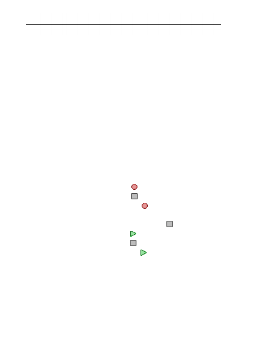
• Record audio comments:
1. Start recording: Press [
].
2. Stop recording: Press [ ].
> Continue recording: Press [ ] again.
• Play recording:
1. Select beginning of recording: Press [
] again.
2. Start playback: Press [ ].
3. Stop playback: Press [ ].
> Continue playback: Press [ ] again.
33
www.GlobalTestSupply.com
Page 34
6 Using the product
• Change audio comment:
• Delete recording:
• Exit Audio dialogue:
1. Selection position from which the recording should be
overwritten: Begin playback with [ ] and stop at the
desired point [
2. Use [ ] to overwrite the recording as of the desired point.
> Press [
- The complete recording is deleted.
> Press [ESC].
].
].
34
www.GlobalTestSupply.com
Page 35
7 Maintaining the product
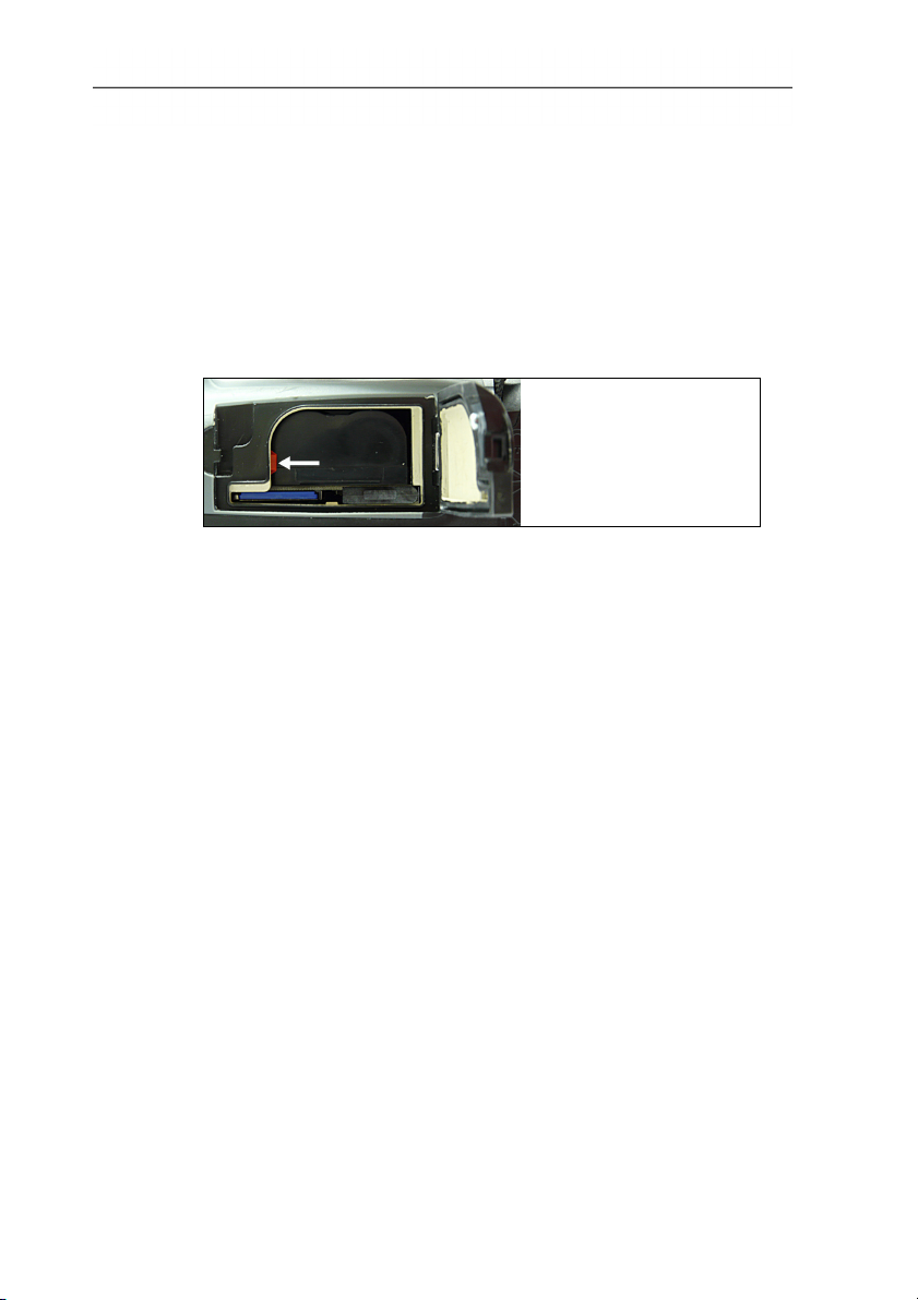
Changing the rechargeable battery
To prevent losing the instrument settings: Only change the
rechargeable battery when a buffer battery is inserted in the
instrument or the mains unit is connected.
1. Unlock the battery compartment cover.
2. Press the unlocking button.
7 Maintaining the product
- The rechargeable battery is released and sticks out a little from
the rechargeable battery slot.
3. Pull the rech. batt. completely out of the batty shaft.
4. Slide the rech. batt. completely into the battery shaft, until it
clicks into place.
- The camera starts automatically.
Clean thermal imager
> If the housing of the thermal imager is dirty, clean it with a damp
cloth. Do not use any aggressive cleaning agents or solvents!
Weak household cleaning agents and soap suds may be used.
Cleaning lens/infrared protection glass
> Large dust particles can be removed with a clean optical
cleaning brush (available in specialized photography shops).
> Use a lens cleaning cloth for slight contamination. Do not use
rubbing alcohol!
Changing the buffer battery
To prevent losing the instrument settings: Only change the buffer
battery when a charged rechargeable battery is inserted or the
mains unit is connected.
35
www.GlobalTestSupply.com
Page 36
7 Maintaining the product
1. Open the rech. batt. cover on the underside of the camera.
2. Pull the battery holder together with the buffer battery out of the
battery shaft.
3. Remove the exhausted battery from the holder and insert new
battery (type CR 1632).
CAUTION
Incorrectly inserted batteries can damage the product!
> When inserting the batteries, observe the polarity (label on
inside of cover).
4. Push the battery holder into the battery shaft.
36
www.GlobalTestSupply.com
Page 37

8 Tips and assistance
8.1. Questions and answers
Question Possible causes/solution
Message Backup battery
empty or not present is
shown.
1. Confirm the message with [OK].
2. Change buffer battery, see
Changing the buffer battery, page
35.
Error No memory card
inserted! is shown.
Memory card defective or not inserted.
1. Confirm the message with [OK].
2. Check or insert memory card.
Error Memory card full! is
shown.
Insufficient memory present.
1. Confirm the message with [OK].
2. Insert new memory card.
Error No lens/wrong lens!
is shown.
1. Switch off thermal imager.
2. Check lens
> Change lens if necessary.
Message Charging not
possible! is shown.
Ambient temperature is outside the
permissible range for charging the
battery.
1. Confirm the message with [OK].
2. Keep to the permissible ambient
temperature.
Error Permissible
instrument temperature
exceeded! is shown.
1. Switch off thermal imager.
2. Let instrument cool off and keep to
the permissible ambient
temperature.
--- or +++ is shown instead
of the reading.
Reading is outside of the measuring
range.
> Change measuring range.
xxx is shown instead of the
reading.
Reading cannot be calculated.
> Check parameter settings for
plausibility.
8 Tips and assistance
37
www.GlobalTestSupply.com
Page 38

8 Tips and assistance
If we could not answer your question, please contact your dealer or
Testo Customer Service. For contact details see the rear side of
8.2. Accessories and spare parts
this document or the web page www.testo.com/service-contact
Description Article no.
Lens protection glass 0554 8805
Additional battery 0554 8852
Fast battery charger 0554 8851
Aluminium tripod 0554 8804
Mains unit 0554 8808
SD card 0554 8803
USB cable 0449 0047
Adhesive emission tape 0554 0051
Automotive charging adapter 0554 8817
Retrofit telephoto lens Testo Service
ISO calibration certificate for thermal
imager:
• Calibration points 0 °C, 25 °C, 50 °C
in measuring range -20 °C...100 °C
• Calibration points at 0 °C, 100 °C,
200 °C in measuring range 0 °C...280 °C
• Freely selectable calibration points in the
range -18 °C...250 °C
0520 0489
0520 0490
0520 0495
38
For further accessories and spare parts, please refer to the product
catalogues and brochures or look up under www.testo.com
www.GlobalTestSupply.com
Page 39

www.GlobalTestSupply.com
Page 40

0970 8760 en 01 V01.06 en-GB
www.GlobalTestSupply.com
 Loading...