

Page 1
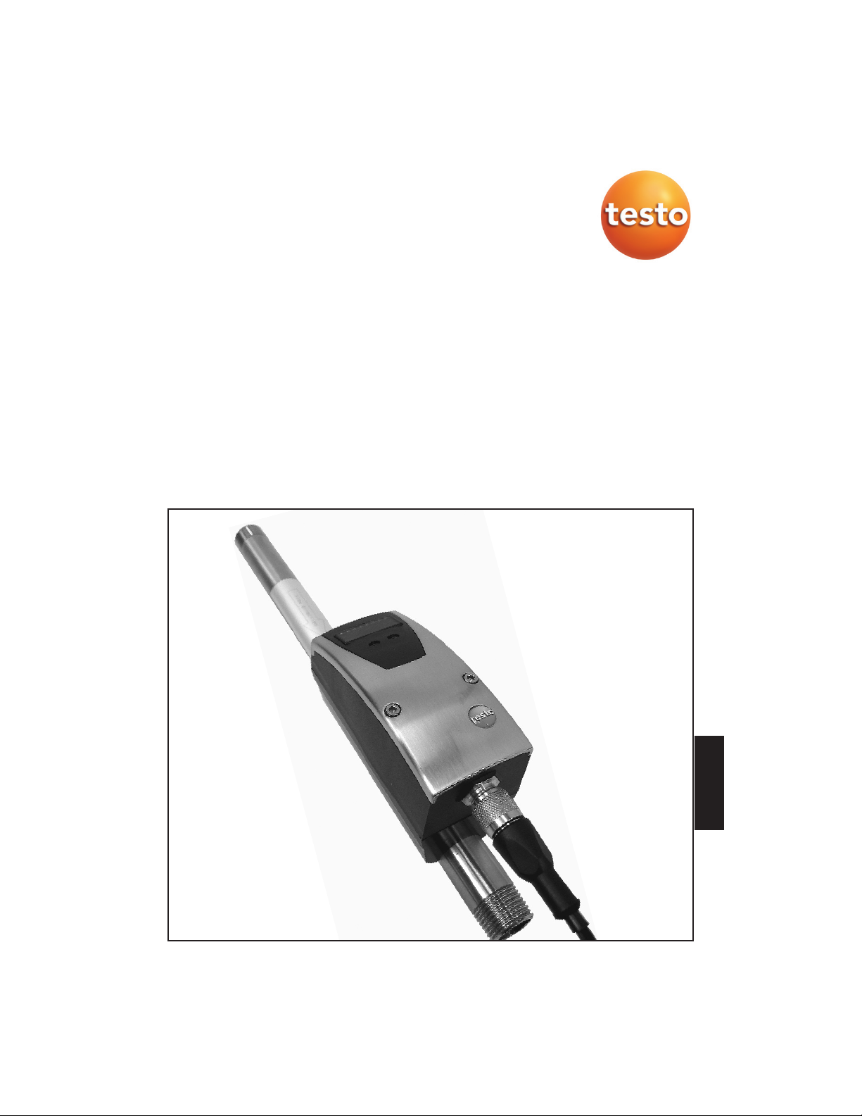
testo 6440
Compressed air counter
Bedienungsanleitung de
Instruction manual en
ENGLISH
Find Quality Products Online at: [email protected]
www.GlobalTestSupply.com
Page 2

Contents
Safety advice ..................................................................................Page 33
Intended purpose............................................................................ Page 34
Area of application .......................................................................... Page 35
Installation ...................................................................................... Page 36
Electrical connection ...................................................................... Page 38
Operation and display elements...................................................... Page 39
Types of operation............................................................................Page 40
Programming .................................................................................. Page 42
Menu overview ................................................................................Page 43
Adjustable parameters ....................................................................Page 44
Parameterization of outputs ............................................................Page 49
Switch outputs ..........................................................................Page 49
Analog output ............................................................................Page 50
Setting pulse output (Pulse / Pre-selection counter) ..................Page 52
Operation / Maintenance ................................................................ Page 56
Technical data ................................................................................ Page 57
Ordering data ..................................................................................Page 58
Dimensional drawings .................................................................... Page 59
32
Find Quality Products Online at: [email protected]
www.GlobalTestSupply.com
Page 3

Safety advice
Please read the description of the instrument before putting it to
use. Make absolutely sure that the product is unconditionally suited
to the respective application.
Work on compressed air systems, as well as installation, adjustment for operation and commissioning of the instrument may only
be carried out by trained expert staff. The recognized technical
rules, as well as security and accident prevention regulations, must
be observed.
Before installation or deinstallation of components in the compressed air system, ascertain that the system has been shut down and
is pressureless.
Before commissioning/re-starting the system, ascertain that neither
persons nor objects are endangered by moving parts.
Disregarding operating instructions or technical information can
lead to personal injury or damage to objects.
In all applications, verify the compatibility of the product materials
to the media to be measured.
ENGLISH
33
Find Quality Products Online at: [email protected]
www.GlobalTestSupply.com
Page 4
Intended purpose
The instrument records the norm volume flow of the working compressed air according to the calorimetric measurement principle
(norm volume flow according to ISO 2533, i.e. volume flow at 1013
hPa, 15 °C and 0 % relative humidity.
• Use in working compressed air systems. The general operating
conditions of compressed air systems apply.
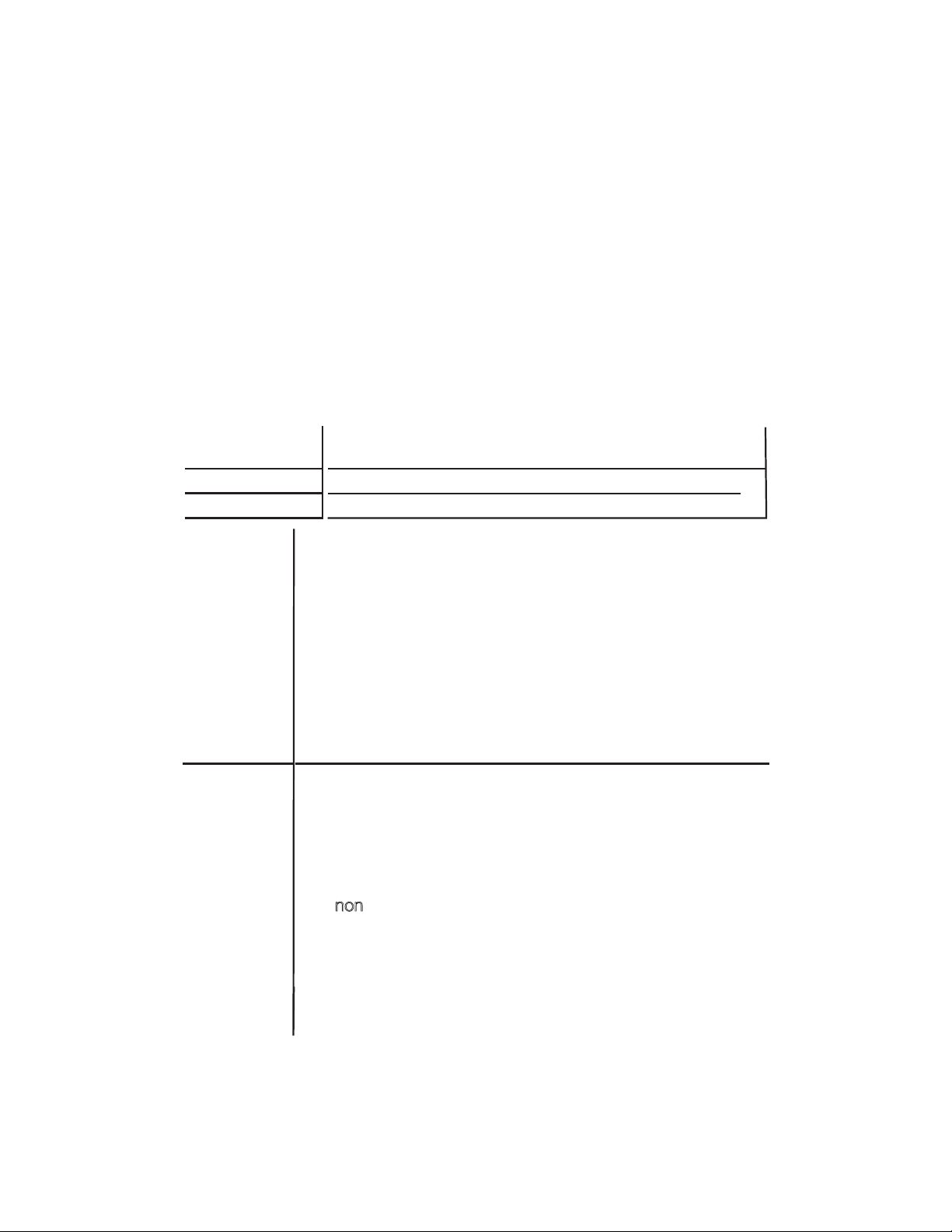
The quality class of the the working compressed air influences the
•
accuracy of the measurement:
Quality class acc.
to ISO 8573-1
1-4-1
3-4-4
Display
Signal
output
Measurement inaccuracy
± (3% of meas. value + 0,3% of meas. range final value)
± (6% of meas. value + 0,6% of meas. range final value)
3
• Current volume flow in Nm
1 or 2 lights up.
• Current consumption quantity in Nm
ween 0.001 m
1/1000 of the value is displayed and the LED 10
that it must be multiplied by a factor of 1000.
• Consumption quantity before the last reset in Nm
the display of this value, LED 3 flashes.
• Current media temperature in °C. LED 4 lights up.
The display unit is set by programming (→ page 12 ff). It can
be temporarily changed in measurement mode (briefly press
the “Set” button).
Output 1 (3 selection possibilities programmable)
• Switch signal: Limit value for volume flow; hysteresis or window function; closer or opener, cf. page 19 f.
• Pulse sequence for quantity counter: Output 1 gives a
counting pulse every time a set flow rate is reached, cf.
page 22 f.
• Switch signal for pre-selection counter (for time-dependant
or n
on-time-dependant quantity monitoring.
Output 2 (2 selection possibilities programmable)
• Switch signal: Limit value for volume flow; hysteresis or window function; closer or opener, cf. page 19 f.
• Analog signal (4...20 mA) for volume flow, cf. page 22 f.
3
and 4000*103m3, at values > 9 999m3,
/h or Nl/min (4-digit display). LED
3
(4-digit display bet-
3
indicates
3.
During
34
Find Quality Products Online at: [email protected]
www.GlobalTestSupply.com
Page 5
Area of application
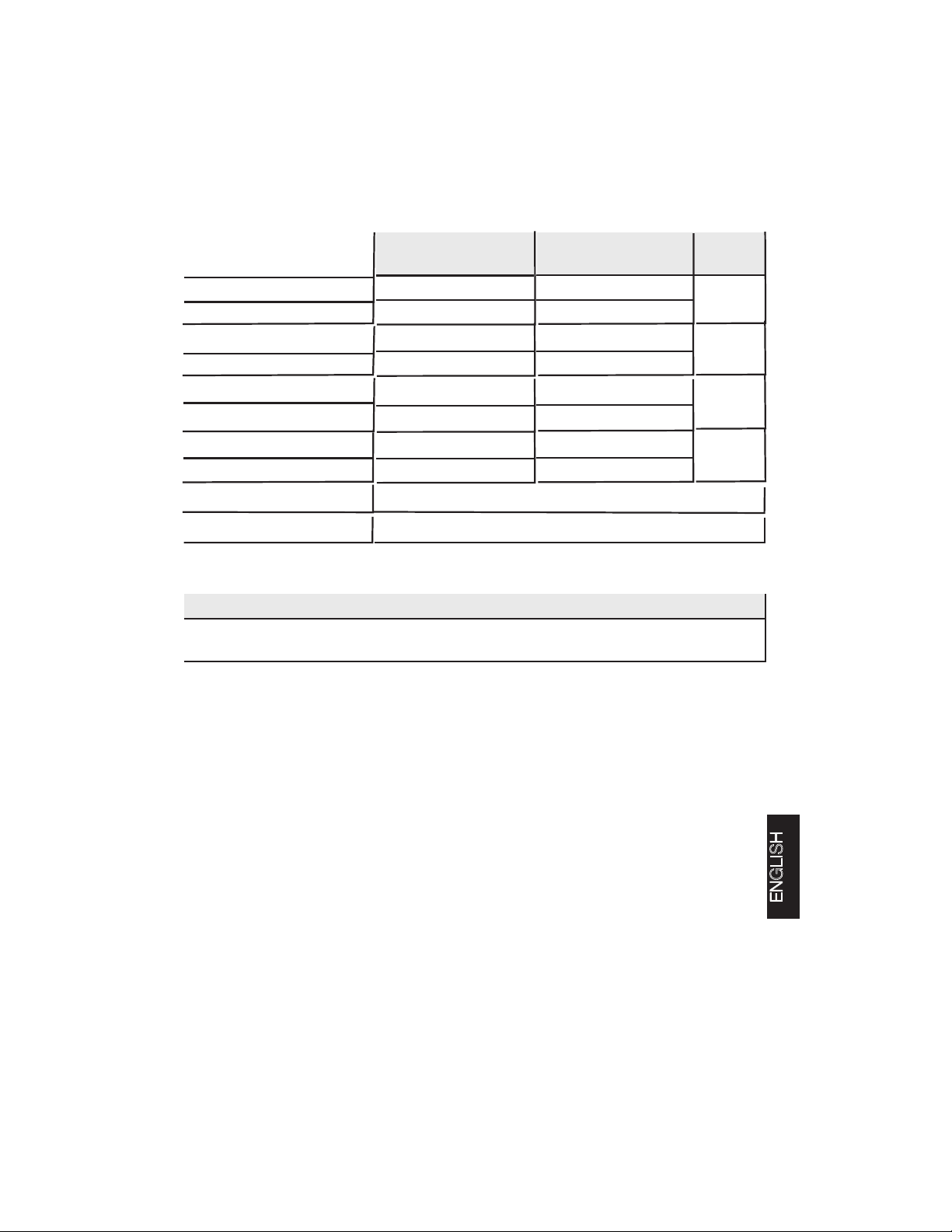
Meas. / working
range
Volume flow in Nm3/h
Volume flow in Nl/min
Volume flow in Nm3/h
Volume flow in Nl/min
Volume flow in Nm3/h
Volume flow in Nl/min
Volume flow in Nm3/h
Volume flow in Nm3/min
Quantity counter in m
Pressure loss
Thanks to their small size, the measuring elements present only a minimum
of exposed surfaces. Pressure loss is therefore negligible (typically 1 mbar).
0.25 (0,3) ... 75.0
4 ... 1250
0.75 ...225
1.3...3750
1.3...410
22.2...6830
2.3 700
0.04 ... 11.67
3
0.001 ... 4000 × 10
0 ... +60Temperature in °C
in brackets: value shown in display
Recording / dis-
play range
0.0 ... 90.0
0 ... 1500
0.0 ... 270
0 ... 4500
0...492
0 ... 8200
0...840
0 ... 14
3
Instru-
ment
6441
6442
6443
6444
ENGLISH
35
Find Quality Products Online at: [email protected]
www.GlobalTestSupply.com
Page 6
Installation
Follow the regulations and instructions for the installation and
operation of compressed air systems.
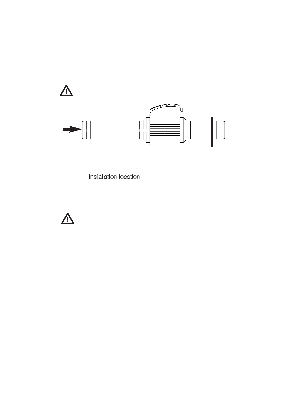
Thread for installing e.g. a
pipe collar with/without
sleeve nut
{
Install the testo 6440 so that the flow rate direction and the marking
arrow are pointing in the same direction.
Preferable installation location:
Behind the compressed air dryer / close to the consumer.
Installation in front of the maintenance unit is also possible. (If oil is
used for the consumer, the instrument must be installed in front of
the lubricator).
In the middle of the rating plate is a respiration filter which pro-
tects the interior of the housing from condensation. Please do
not cover this up, and protect it from damage.
testo 6443/6444:
Removal of thread for Mapress
installation possible
Due to its ability to measure bidirectionally, testo 6440 can also be
applied in ring lines. The actual flow direction is then detected by a
seperate flow direction detector and transmitted to the PLC. Values
can thus be added or subtracted in the PLC depending on their flow
direction.
In order to maintain the specified measurement accuracy, the following installation requirements must be observed.
- defined inflow/outflow routes (straight lengths of pipe).
- constant flow profile over time.
36
Find Quality Products Online at: [email protected]
www.GlobalTestSupply.com
Page 7
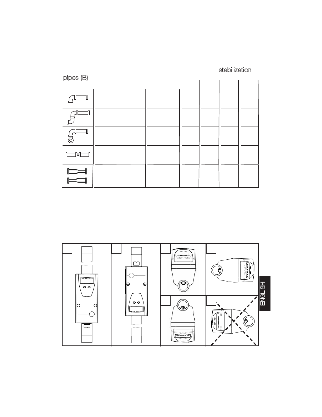
For disturbances on the inflow side, additional straight stabilization
pipes (B) are recommended:
6441 6442 6443
6444
B
90°-elbow
two 90°-elbows,
B
B
one level
two 90°-elbows,
two levels
valve, slide valve
B
Changing the pipe
diameter
B = 5 x D*
B = 10 x D*
B = 15 x D*
B = 35 x D*
6441/6442:
B=5xD*
6443: B=13xD*
6444: B=15xD*
✓✓✓✓
✓
+35
mm
+360
mm
✓
+40
mm
+590
mm
✓✓
+120
mm
+320mm+490
+1100mm+1500
+230mm+490
+240
mm
mm
mm
mm
Installation position
• Allowed installation positions: measurement stretch (straight pipe
length) vertical, any position (ill. 1, 2); measurement stretch horizontal, instrument vertical (ill. 3, 4), instrument lying sideways, measurement stretch left (ill. 5).
• Avoid the position ill. 6 (instrument sideways, measurement stretch
right). The respiration filter points upwards, which is to be avoided.
1 2 3 5
64
Find Quality Products Online at: [email protected]
www.GlobalTestSupply.com
ENGLISH
37
Page 8
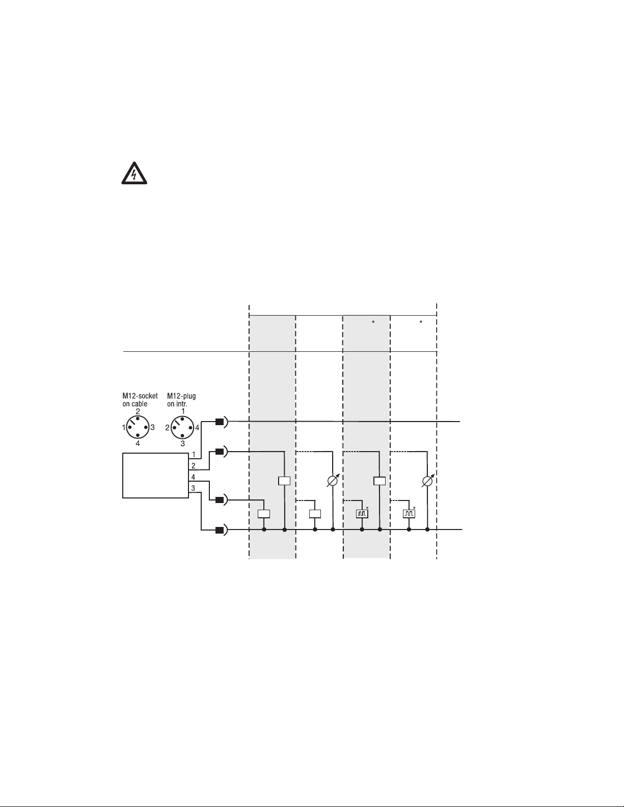
Electrical connection
L + (19...30 VDC)
The instrument may only be connected by an electrician. Follow
the national and international regulations on the installation of
electro-technical systems.
Voltage supply according to EN50178, SELV, PELV.
Switch the system to zero potential and connect the instrument
as follows:
Output 1
OUT 1
Output 2
OUT 2
testo
Define
in Menu
OU1
OU2
BN
WH
OUT
2
(Switch)
Hno / Hnc
Fno / Fnc
Hno / Hnc
Fno / Fnc
(Switch)
4 alternatives
(Switch)
Hno / Hnc
Fno / Fnc
Current
output
6440
BK
BN = brown
WH = white
BK = black
BU = blue
* If ImPR = Yes ➝ Pulse output,
ImPR = No ➝ Switch output (pre-selection counter,
cf. page 22
OUT
1
BU
ImP
(Impulse)
I
Hno / Hnc
Fno / Fnc
(Switch)
ImP
(Impulse)
I
Current
output
0 VDC
38
Find Quality Products Online at: [email protected]
www.GlobalTestSupply.com
Page 9
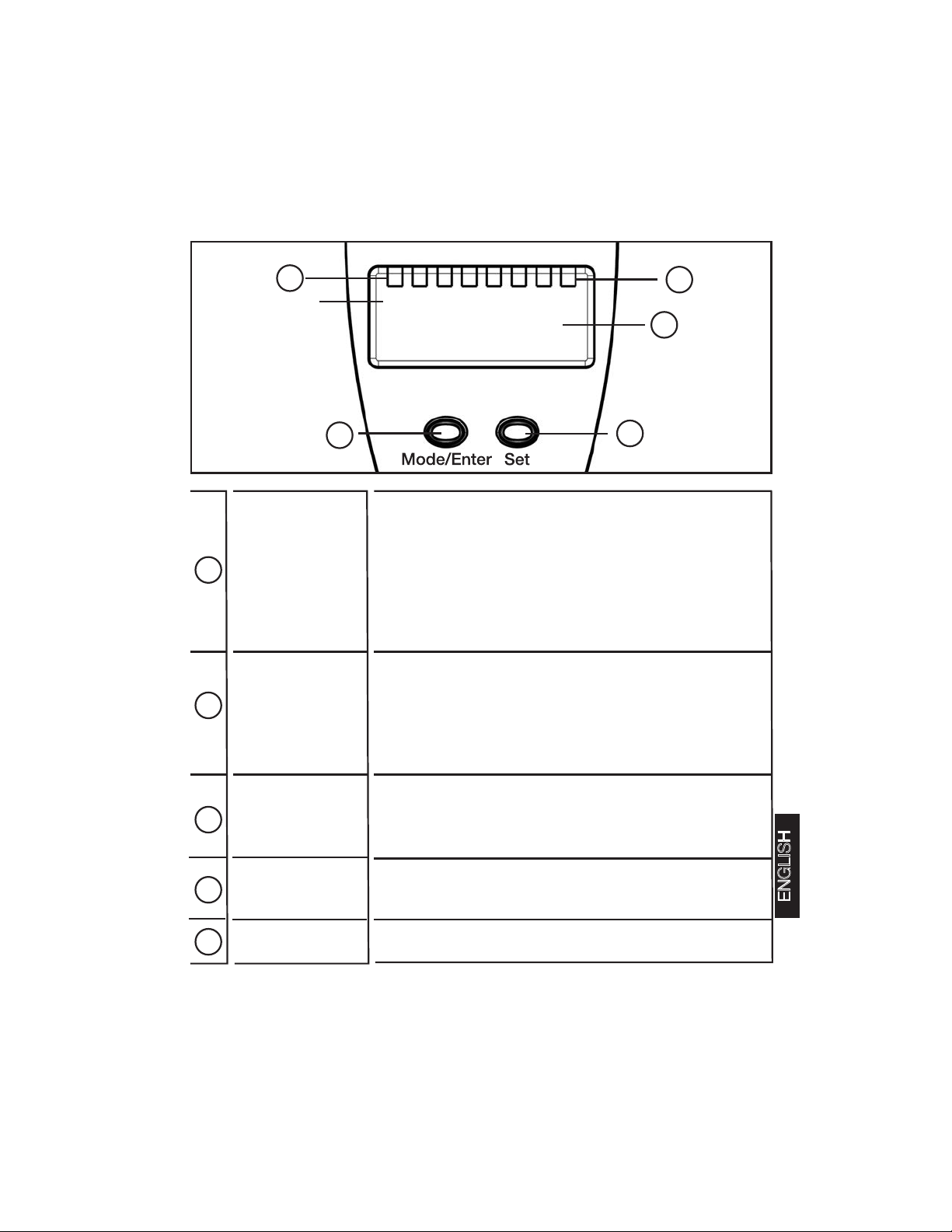
Operation and display elements
LED number
4 x LED green
1
3 x LED yellow
2
1
1 2 3 4 5 6 7
5
LED lit = display unit set:
- LED 1 (Nl/min, with 6444: Nm3/h) / LED 2 (Nm
Flow rate display (norm volume flow).
- LED 3 (Nm3): Quantity counter
(current consumption quantity/totalisator)
LED 3 flashing: stored counter value
(= counter value before last reset).
- LED 4 (°C): Current media temperature in °C.
Display function
3
: The value displayed must be multiplied by
- 10
factor 1000 (LED 5)
-
SP1 / SP2: Display of switch status; display lights up
when the respective output is switched through (LED
6/7)
.
4
3
2
3
/h):
4-digit
alpha-numeric
3
4
5
Find Quality Products Online at: [email protected]
display
Programming
button
Set
Prog. button
Mode / Enter
www.GlobalTestSupply.com
- Display of current norm volume flow,
- Display of counter status,
- Display of current media temperature,
- Display of parameters and parameter values.
- Set parameter values (continuous by holding
down, step-by-step by single pressing);
- Change display unit in measuring mode
Selection of parameters and confirmation of parameter values
ENGLISH
39
Page 10

Types of operation
1.Measuring mode
Normal working operation
After switching on the supply voltage, the instrument is in measuring mode. It carries out its measurement and evaluation functions
and provides output signals according to the set parameters.
The Display shows the current measurement values, the green
LEDs give the unit displayed.
The display unit can temporarily be changed (press the “Set” button briefly, after 15s the instrument returns to the display unit set
in the menu item U
The t
otaliser (consumption quantity counter) totals the pulses of
the consumption quantity and shows them in the display as the
current consumption value since the last reset. It periodically
(every 10 minutes) stores the current total value as well as the
amount of time elapsed of the defined automatic reset. After a
drop in voltage, these values are available as the current status of
the totaliser (the possible loss of data can amount to a maximum
of 10 minutes).
ni.
The two yellow LEDs on the right indicate the switch status of the
outputs.
2.Programming mode
2.1 Displaying parameters
Display of parameters and set parameter values
The instrument is switched to display mode by briefly
pressing the “Mode/Enter” button. Internally it stays in
measurement mode. The set parameter values can be read
independently of this:
• Briefly pressing the “Mode/Enter” button scrolls through the
parameters.
40
Find Quality Products Online at: [email protected]
www.GlobalTestSupply.com
Page 11

• Briefly pressing the “Set” button shows the respective
parameter value for approximately 15s. After a further 15s,
the instrument returns to measurement mode.
2.2 Setting parameters
Setting parameter values
The instrument switches from display mode to programming
mode if a parameter has been selected and the “Set” button
is pressed for longer than 5s (the parameter value is
displayed flashing, then continuously increased). Here too,
the instrument remains in working operation. It continues to
carry out its monitoring functions with the existing
parameters, until the alteration has been completed.
You can change the parameter value with the help of the
“Set” button and confirm with the “Mode/Enter” button. The
instrument returns to measurement mode, if no buttons are
pressed for 15s afterwards. For details cf. page 12 ff.
ENGLISH
41
Find Quality Products Online at: [email protected]
www.GlobalTestSupply.com
Page 12
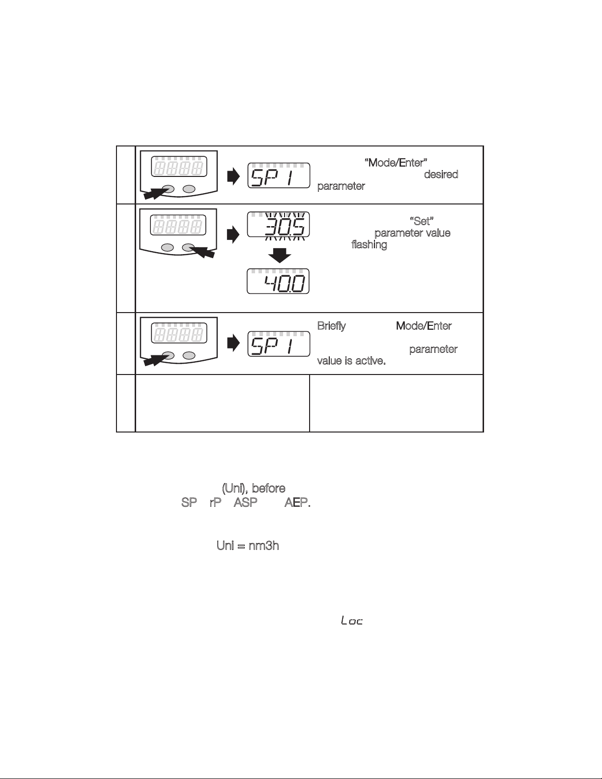
Programming
1
Mode/Enter Set
Press the “Mode/Enter” button
several times, until the d
parameter appears in the display.
esired
Mode/Enter Set
Press and hold the “
The current p
played f
arameter value is dis-
lashing for 5s.
Set” button.
2
after this it increases*
(in steps by pressing singly or continuously by pressing and holding
the button.)
B
riefly press the Mode/Enter but-
3
4
Mode/Enter Set
Changing further parameters:
Start again with step 1.
*Lowering value: Allow the display to run through to the maximum
setting value. After this the run-through starts again from the minimum value.
Set the display unit (
parameters S
Px, rPx, ASP and AEP. That way you avoid rounding
Uni), before you determine the values for the
up/down errors in the internal conversion into other units, and are
provided with exactly the values required.
Status at delivery: U
ni = nm3h
ton (= OK). The parameter is again
displayed, the new p
value is active.
End programming:
Wait 15 s or press the Mode/Enter
button, until current measurement
reading reappears
arameter
If no button is pressed for 15 s during setting, the instrument returns
to measurement mode with unchanged values.
The instrument can be electronically locked so that unintentional
false entries are avoided: Press both programming buttons for
approx. 15 s in measurement mode, until is displayed. The
parameters can still be called up / read.
42
Find Quality Products Online at: [email protected]
www.GlobalTestSupply.com
Page 13
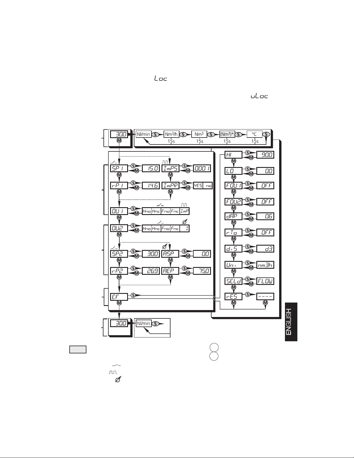
If the instrument is locked, appears briefly in the display if an
attempt is made to change parameter values.
To unlock, press both buttons again for approx.15 s, until is
displayed.
Menu overview
Measuring
mode
Output 1
(OUT 1)
Output 2
(OUT 2)
①
Extended
functions
Measuring
mode
(Nm3)*
Switch output
Pulse output
Current output
Find Quality Products Online at: [email protected]
= Nm3before last reset
- OUx = Hno, Hnc, Fno, Fnc (cf. page. 19)
- OU1 = ImP (cf. page. 22)
- OU2 = I (cf. page. 20)
www.GlobalTestSupply.com
... (see
above.)
① Short-term
display unit, cf. p. 10
Continuous display unit
M = Mode/Enter
S = Set
ENGLISH
43
Page 14
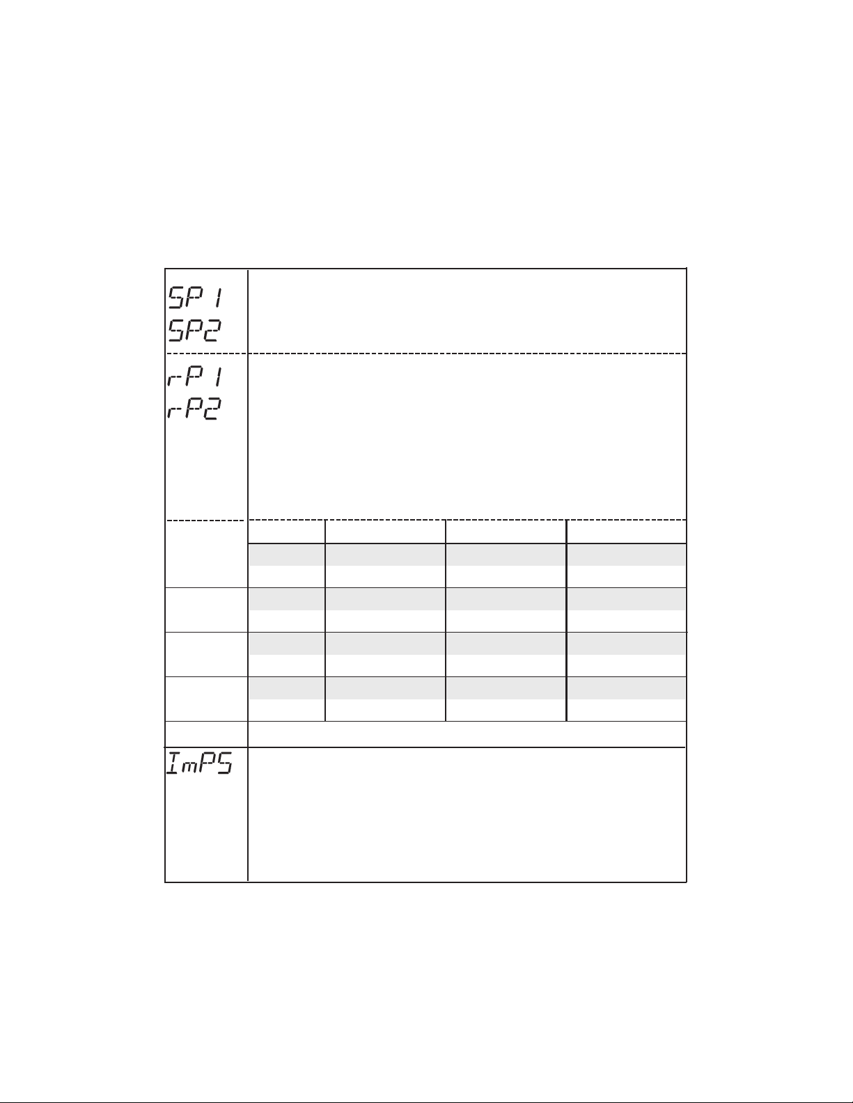
Adjustable parameters
See the menu overview on page 13 for the structure of
the menu.
Switch point 1 / 2
Upper limit value, at which the output changes its switch status,
see page 19.
SPx is only active, if OUx = Hno, Hnc, Fno or Fnc.
Return switch point 1 / 2
Lower limit value,at which the output changes its switch status,
see page 19.
rPx is always smaller than SPx. Values can only be entered
which are lower than SPx.
When the switch point is changed, the return switch point
changes with it (the interval between SPx and rPx remains constant). rPx is only active if OUx = Hno, Hnc, Fno or Fnc,
cf. page 16. Adjustment ranges (Norm volume flow):
testo
6441
testo
6442
testo
6443
testo
6444
(OU1 = lmP)
SP1 / SP2
Nm3/h
Nl/min
Nm3/h
Nl/min
Nm3/h
Nl/min
Nm3/h
3
Nm
/min
Pulse / Counter setting
Determines the pulse value (lmPR = Yes) / the value for the preselection counter (lmPR = No).
Adjustment range: 0.001 ... 1 000000 Nm
Pulse length: min. 0.02s / max. 2s.
ImPS is only active, if OU1 = ImP.
Setting the value (cf. page 22)
0.7 ... 75.0 0.3 ... 74.6
2.0 ... 225 0.9 ... 223.9 0.1
3.5 ... 410 1.5 ... 408 0.5
6 ... 700 3 ... 696 0.5
rP1 / rP2
3
in steps of
0.1
111 ... 1250 5 ... 1244
134 ... 3750 15 ... 3731
1060 ... 6830 30 ... 6800
0.010.11 ... 11.67 0.05 ... 11.61
44
Find Quality Products Online at: [email protected]
www.GlobalTestSupply.com
Page 15
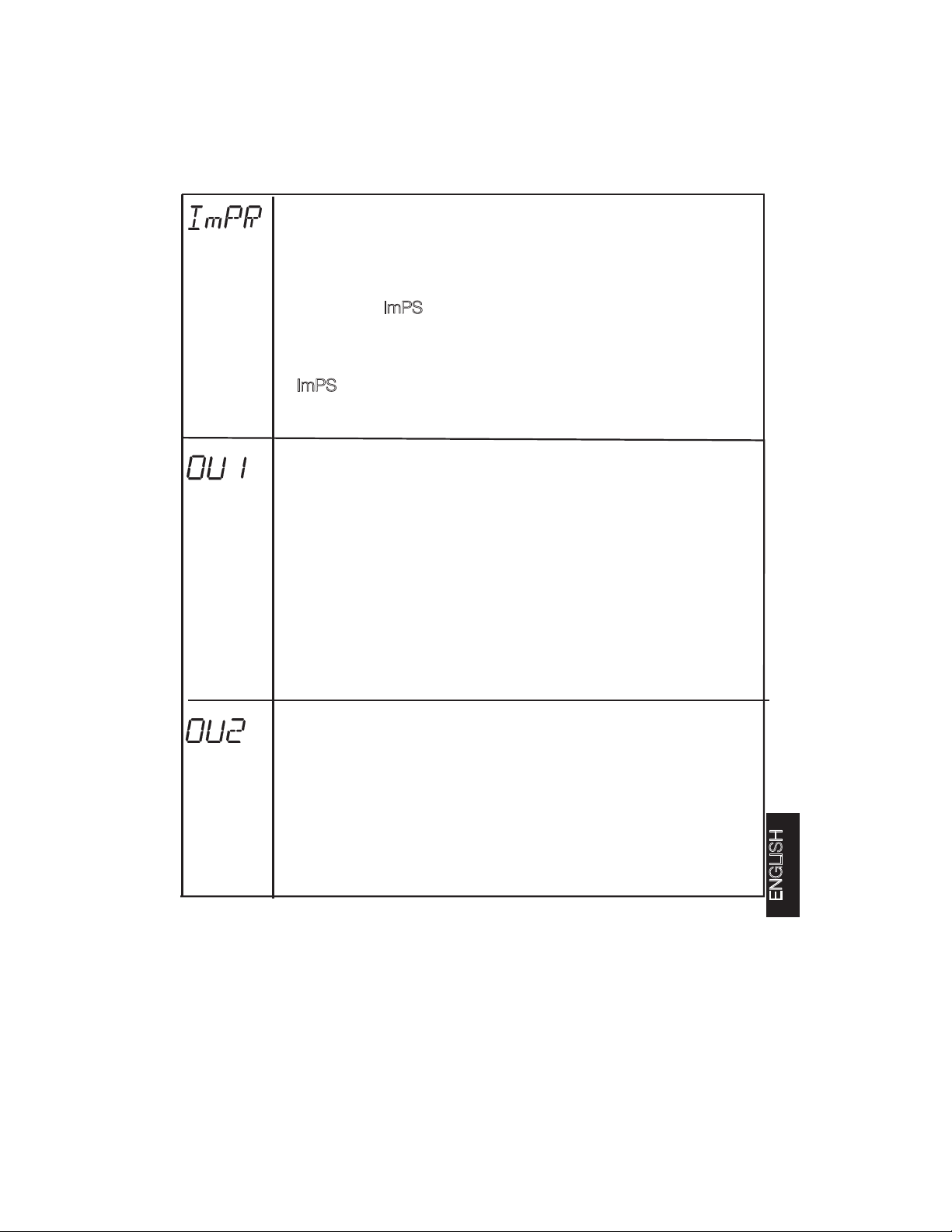
(OU1 = lmP)
Repeat pulse
Determines which signals are given by the counter at output 1,
2 settings can be selected (cf. page 22):
• YES: Repeat pulse is active (= volume flow-dependent coun-
ter function): Output 1 gives one counter pulse, each time the
value set in I
•
Configuration for Output 1
One of the following 5 functions can be set:
- Volume flow-dependent switch output:
• Hno = Hysteresis function / normally open (Closer) → p. 19
•
•
•
- Consumption-dependent pulse output or consumption
•
• Factory setting = Hno
Repeat pulse is inactive (the counter works as a pre-
NO:
selection counter, i.e. as a quantity-dependent switch output): Output 1 switches (OUT1 = ON), when the value set in
ImPS is reached. It remains switched until the counter is
reset, parameter rTo (see page 17). ImPR is only active if
OU1 = ImP.
= Hysteresis function / normally closed (Opener) → p. 19
Hnc
= Window function / normally open (Closer) → p. 19
Fno
= Window function / normally closed (Opener) → p. 19
Fnc
dependent switch output:
= Pulse order or On / Off signal for pre-selection counter
ImP
(→ Parameter ImPS and ImPR), cf. page 22
mPS is reached.
Configuration for Output 2
One of the following 4 switch functions or 1 analog signal for
flow rate are selectable:
• Hno = Hysteresis function / normally open (Closer) → p. 19
•
•
•
•I= Analog signal (4 ... 20mA) → cf. page 20
• Factory setting = Hno
= Hysteresis function / normally closed (Opener) → p. 19
Hnc
= Window function / normally open (Closer) → p. 19
Fno
= Window function / normally closed (Opener) → p. 19
Fnc
ENGLISH
45
Find Quality Products Online at: [email protected]
www.GlobalTestSupply.com
Page 16
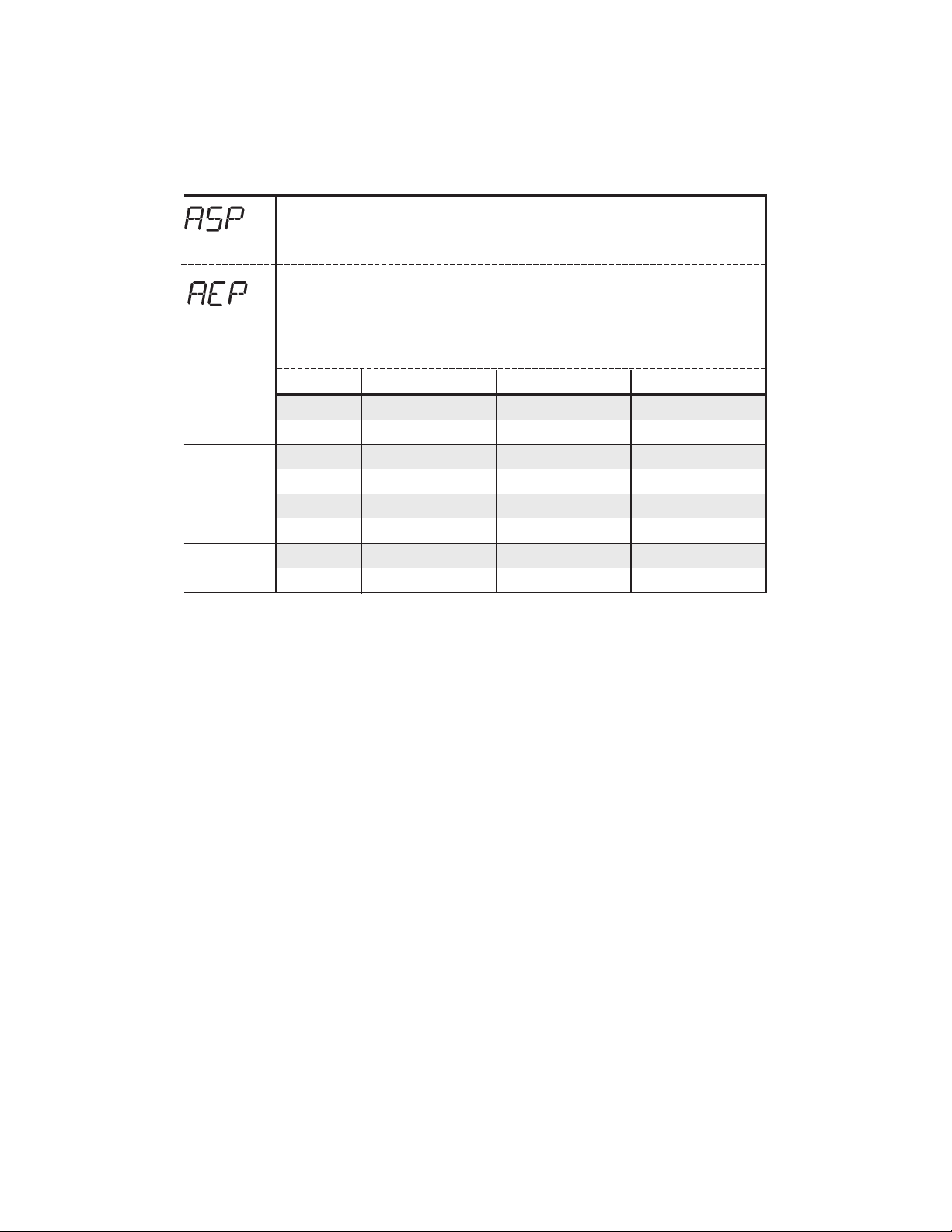
(OU2 = I)
(OU2 = I)
Analog starting point
Measurement value at which 4 mA are output, cf. page 20.
ASP is only active, if OU2 = I.
Analog end point
Measurement value at which 20 mA are output, cf. page 20.
Minimum distance between ASP and AEP = 25% of maximum
scale value. AEP is only active if OU2 = I.
Adjustment ranges (Norm volume flow):
testo
6441
testo
6442
testo
6443
testo
6444
ASP AEP
Nm3/h
Nl/min 10 ... 938 313 ... 1250
Nm3/h
Nl/min 10 ... 2813 938 ... 3750
Nm3/h
Nl/min 100 ... 5120 1710 ... 6830
Nm3/h
3
Nm
/min
in steps of
0.10.0 ... 56.3 18.8 ... 75.0
0.10 ... 168.8 56.3 ... 225.0
0.50 ... 307.5 102.5 ... 410
10 ... 525 175 ... 700
0.010 ... 8.75 2.92 ... 11.67
46
Find Quality Products Online at: [email protected]
www.GlobalTestSupply.com
Page 17
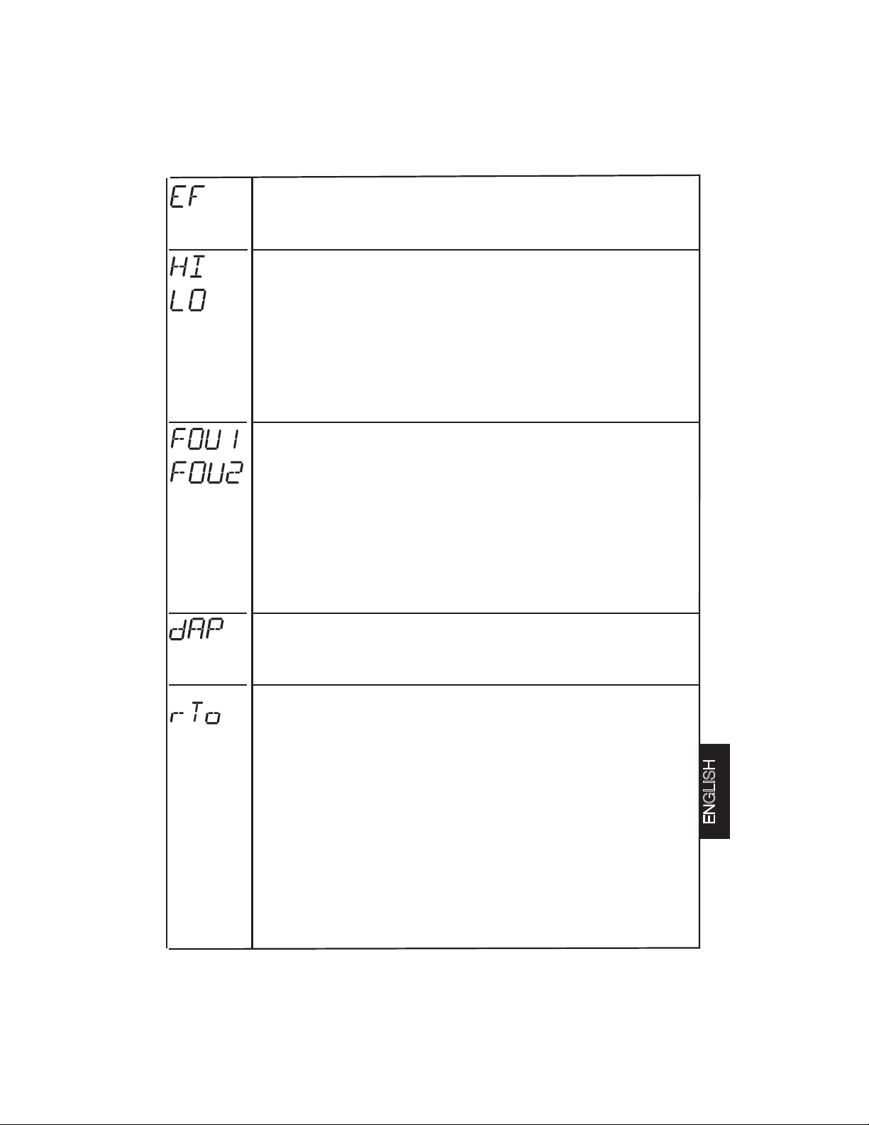
Extended functions
This menu point contains a sub-menu with further parameters.
For access to these parameters, briefly press the Set button.
Min-Max store for volume flow
• HI: Display of highest volume flow value measured
• LO: Display of lowest volume flow value measured
Deleting store:
- Press the“Mode/Enter” button, until HI or LO appears.
- Press the “Set” button and hold down until “- - - -” appears in
the display.
- Then briefly press the “Mode/Enter” button.
It is a good idea to delete the store before using the instrument
for the first time under normal working conditions.
Behaviour of output 1 / 2 in case of error
(Display Err → page 26). 3 settings are settable:
• FOU1/ FOU2 = ON: In error, output 1 / 2 switches ON.
the analog signal of output 2 goes to highest limit stop value
(22 mA)
• FOU1/ FOU2 = OFF: In error, output 1 / 2 switches OFF,
the analog signal of output 2 goes to lowest limit stop value
(3,5mA) = factory setting.
• FOU1 = OU1 / FOU2 = OU2: Output 1 / 2 works as
determined with the parameters OU1 / OU2 independently of
the error.
Damping/delaying measurement value
•Adjustment range: 0 (= dAP not active) /0.2s/0.4s/0.6 s/0.8s/1s.
The setting affects both the display and the outputs; factory setting: 0.6s .
Resetting the quantity counter (see also page 22)
After a set period of time, the counter is automatically deleted
and a new counting interval begins.
The following time span can be selected:
• 1h ... 23h (Reset after 1 ... 23 hours),
• 1d ... 6d (Reset after 1 ... 6 days),
• 1w ... 8w (Reset after 1 ... 8 weeks).
Further adjustment possibilities:
• OFF = Reset after counter overflow = factory setting
(32 bit number overflow, i.e. overflow at 4,000,000.000 Nm³).
• rES.T = manual reset:
The counter is manually reset and a new counting interval
begins: Press the “Set” button, until rES.T appears; then briefly
press the “Mode/Enter”-button.
Manual reset can also be carried out when a time period for
an automatic reset has been set.
Find Quality Products Online at: [email protected]
www.GlobalTestSupply.com
ENGLISH
47
Page 18
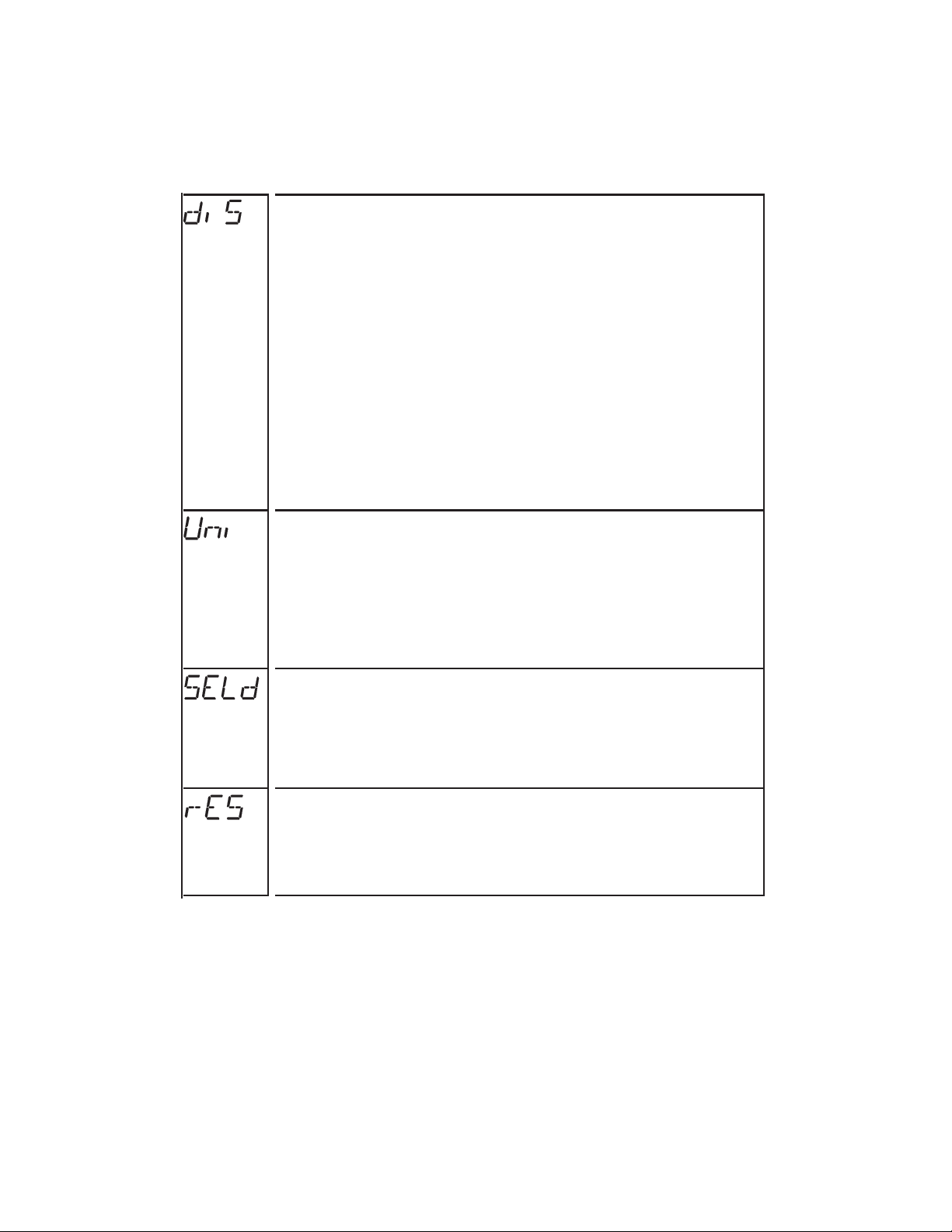
Setting the display
7settings are selectable:
• d1 = Measurement data update every 50 ms.
• d2 = Measurement data update every 200 ms = 0.2 sec.
• d3 = Measurement data update every 600 ms = 0.6 sec.
The measurement data update affects only the display. It has no
effect on the outputs.
• rd1, rd2, rd3 = Display as d1, d2, d3; but rotated by 180°.
• OFF = The measurement data display is switched off in
measurement mode.
The switch status LEDs remain active when the display is
switched off.
Factory setting: d3.
Display unit for flow rate
2 settings are selectable:
• Lmin = Flow rate in norm litres / minute
• nm3h = Flow rate in norm cubic metres / hour
Set the display unit before you set the values for the parameters
SPx, rPx, ASP and AEP. That way you avoid rounding up/down
errors in the internal conversion into other units, and are provided with exactly the values required.
Standard parameter of the display
Setting the measurement parameter which is to be shown in the
display during measurement mode: 2 settings are selectable.
• FLOW = Flow rate set in Uni. (= factory setting)
• TOTL = Counter total in Nm3.
(also if Uni = Lmin)
Restoring factory settings
- Press the “Mode/Enter” button until rES appears.
- Press the “Set”button and hold it down until “- - - -” appears.
- Then briefly press the “Mode/Enter” button.
48
Find Quality Products Online at: [email protected]
www.GlobalTestSupply.com
Page 19
Parameterizing the outputs
Two signals are available (cf. overview page 8), which can be parameterized in the menu (cf. page 14). Please take notice of the
following descriptions.
Setting switch output
In the menu OU1 or OU2 you decide whether the hysteresis function
or the window function is to be selected, cf. page16.
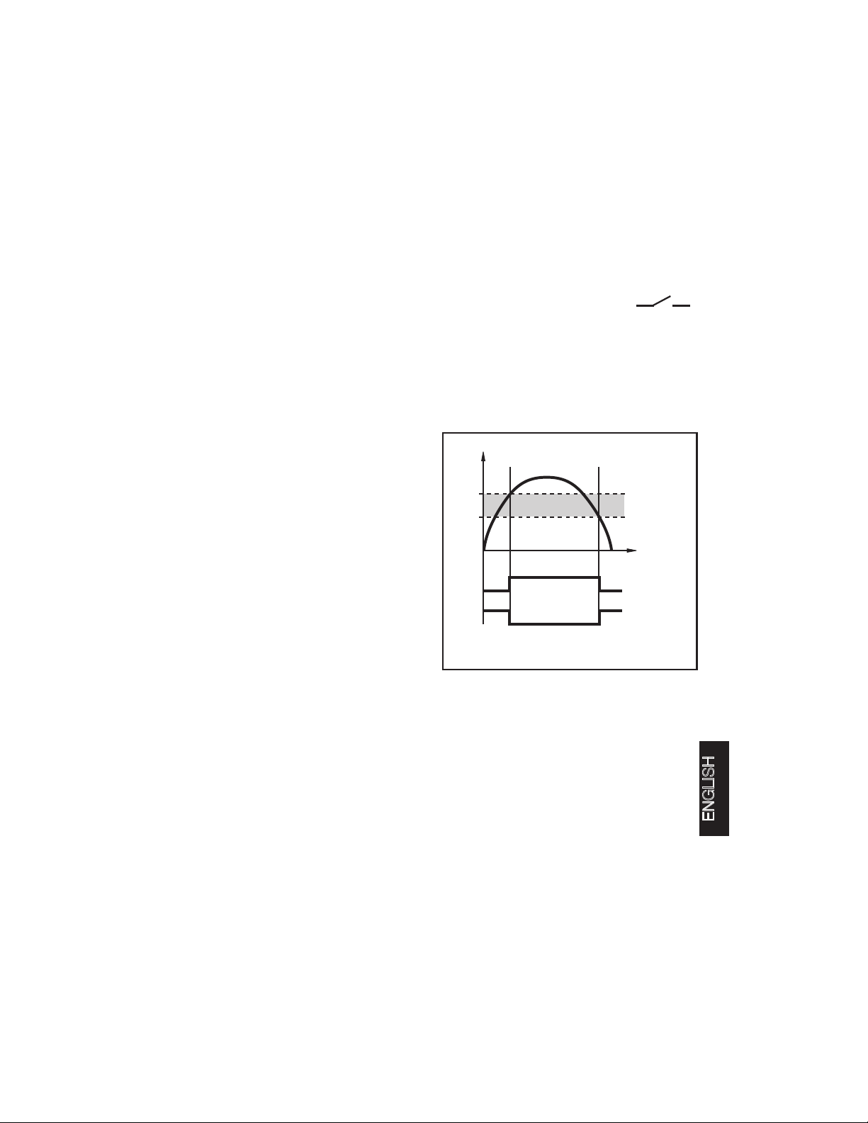
Hysteresis function
The hysteresis keeps the switch
status of the output stable if the
flow rate is fluctuating around the
nominal value. With increasing
flow rate, the output switches
when the switch point (SPx) is
reached. If the flow rate decreases
again, the output only switches back
when the return switch point (rPx) is
reached. The hysteresis is adjustable: First the switch point is determined, then the return switch
point at the desired distance.
SP
rP
Q
Hysteresis
= SP-rP
t
1
0
1
0
(Normally open)
Hno
Hnc
(Normally
closed
)
Example:
3
Switch point = 20Nm
Hysteresis = 2 Nm
3
➔ UNI = nm
/h
➔ SP 1 = 20
/h
3
/h
ENGLISH
➔ rP 1 = 18
49
Find Quality Products Online at: [email protected]
www.GlobalTestSupply.com
Page 20
Window function
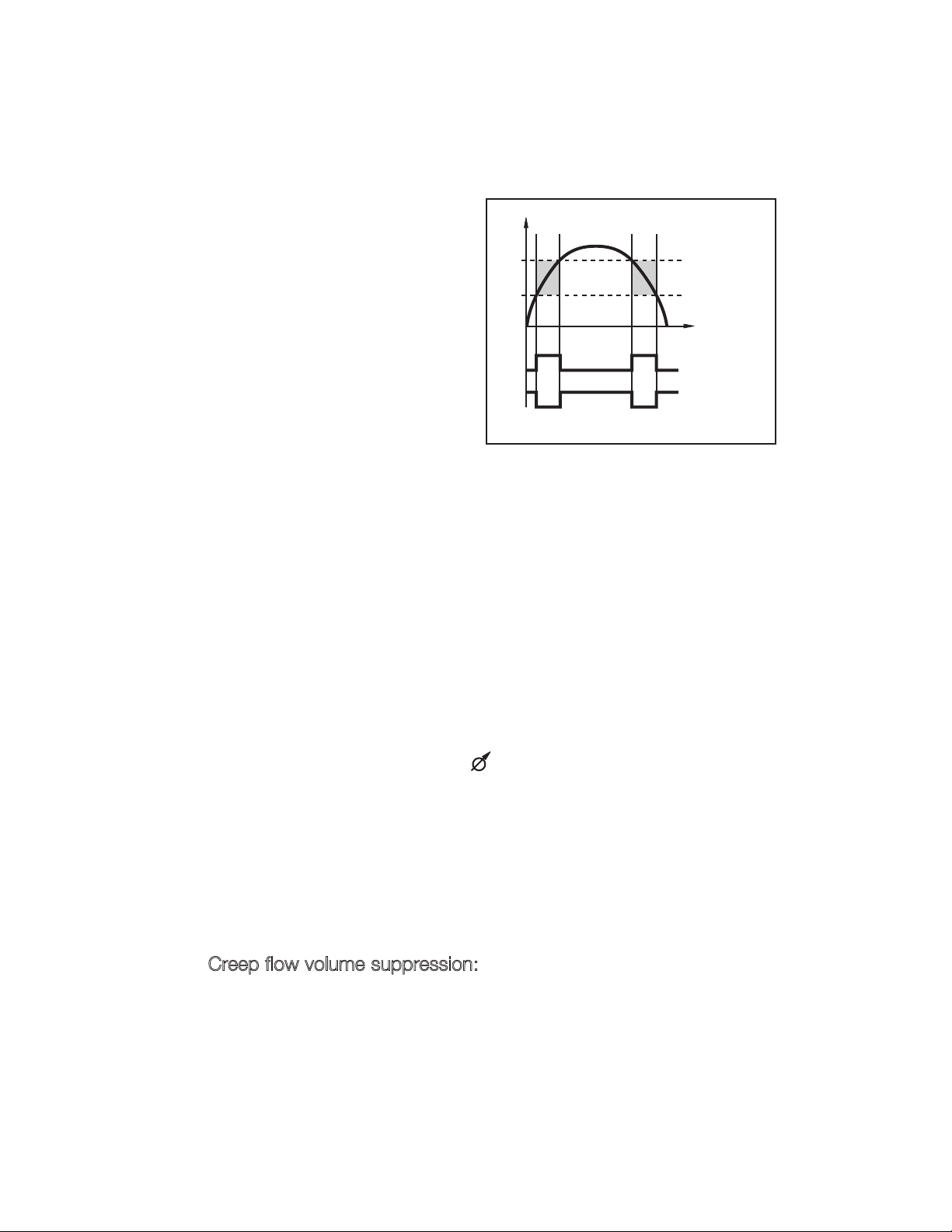
The window function allows a
defined OK-range to be monitored. If the flow rate is fluctuating between switch point (SPx)
Q
SP
rP
and return switch point (rPx),
the output is closed (Fno) or
opened (Fnc).
The size of the window is adjustable by the distance between
1
0
1
0
SPx and rPx. SPx = upper
value, rPx = lower value.
In order to stabilize the switch status, the switch and return
switch points have a set hysteresis of 25% of the maximum
scale value.
Example:
3
Max. allowed value = 22Nm
Min. allowed value = 12 Nm
3
➔ UNI = nm
/h
/h
3
/h
➔ SP 1 = 22
➔ rP 1 = 12
(Normally
t
open)
Fno
Fnc
(Normally
closed
)
Analog output adjustment
A 4...20 mA output with 3-wire technology is available (1 pole = current signal, 1 pole = supply L+, 1 pole common ground for current
signal and supply).
Scaling the measurement range (analog output)
• With the parameter analog starting point (ASP), you determine at
which measurement value the output signal is 4 mA.
reep flow volume suppression: Select a suitable value >0 for
C
ASP, in order to blank out small flow rates which are not to be
recorded.
50
Find Quality Products Online at: [email protected]
www.GlobalTestSupply.com
Page 21
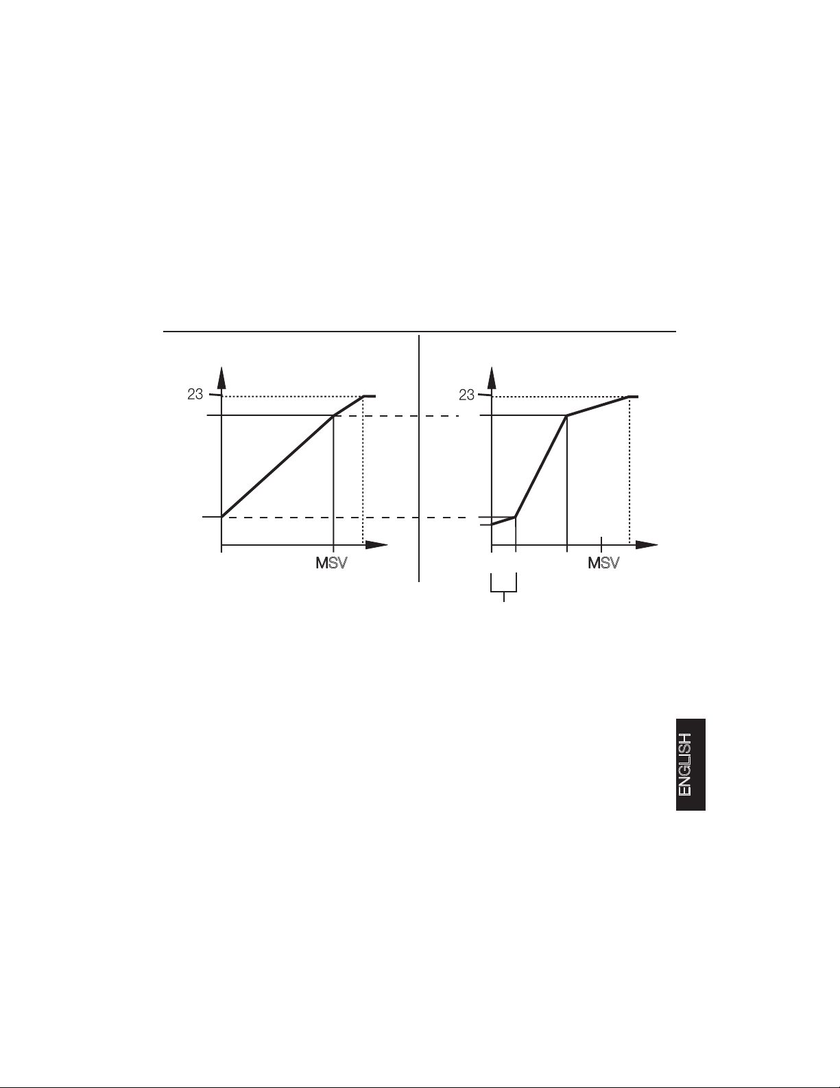
• With the parameter analog end point (AEP), you determine at
which measurement value the output signal is 20 mA.
• Minimum distance between ASP and AEP = 25% of the maximum scale value (MSV), cf. technical data page 27.
I [mA]
20
4
Factory setting
0
MEW
MSV MSV
Q
Measuring range scaled
I [mA]
20
4
3,6
ASP0
”Creep flow volume”
AEP
MEW
The output signal is between 4 and 20mA in the set measuring
range.
Further signals are:
• Flow rate above the measuring range (> MSV):
Output signal > 20mA.
• Flow rate below the measuring range (< ASP):
Output signal between 3,6 and 4mA.
Q
ENGLISH
51
Find Quality Products Online at: [email protected]
www.GlobalTestSupply.com
Page 22
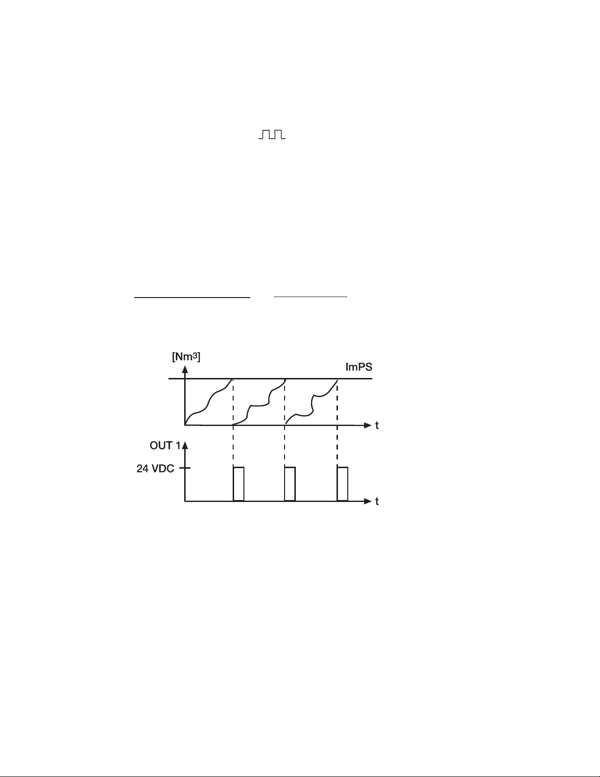
Setting pulse output
The pulse output (OU1 = ImP) can be used in two ways:
1. Counting pulse (ImPR = YES)
A pulse is sent when a defined quantity (pulse value [m³ / Pulse],
defined in the ImPS value, cf. pages 14 and 24) is reached.
For this set ImPR = Yes.
The following applies:
3
(Volume flow [m
ImPS value [m
The relationship pulse to pause is at least 0.5. The pulse lasts
between 0.02 and 2 sec.
/h] =Pulse quantity
3
/Pulse] Hour
value
pulse
pause
pause
pulse
pause
2. Pre-selection counter (ImPR = NO):
When a defined quantity is reached (ImPS value [m³], cf. pages
14 and 24), OUT 1 is switched to ON (i.e. use as a switch ouput).
There are two possibilities:
2.1. Time-independent monitoring of quantity:
(rTo = OFF, see page 17)
When a defined quantity is reached (ImPS value [m³],)
output OUT 1 is switched to ON and remains on until a
manual reset is made (see page 17).
52
pulse
Find Quality Products Online at: [email protected]
www.GlobalTestSupply.com
Page 23
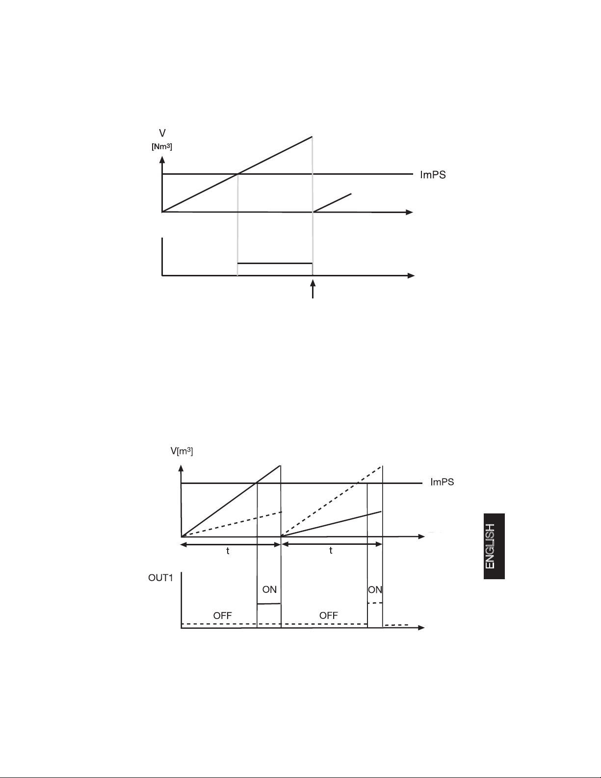
OUT 1
ON
OFF
manual reset, see page 17
OFF
2.2 Time-dependent monitoring of quantity::
(rTo = Time period t, see page 17)
If the defined quantity (ImPS-value [m³], cf. pages 14 and
24) is reached within the time period t, output OUT 1 is
switched to ON.
The counter (V) as well as the OUT 1 is zeroed after time t or
with a manual reset, the next interval starts
Time
Zeit
value
value
Instrument
internal counting
Time
ENGLISH
Switch output
as pre-selection
counter
Time
53
Find Quality Products Online at: [email protected]
www.GlobalTestSupply.com
Page 24
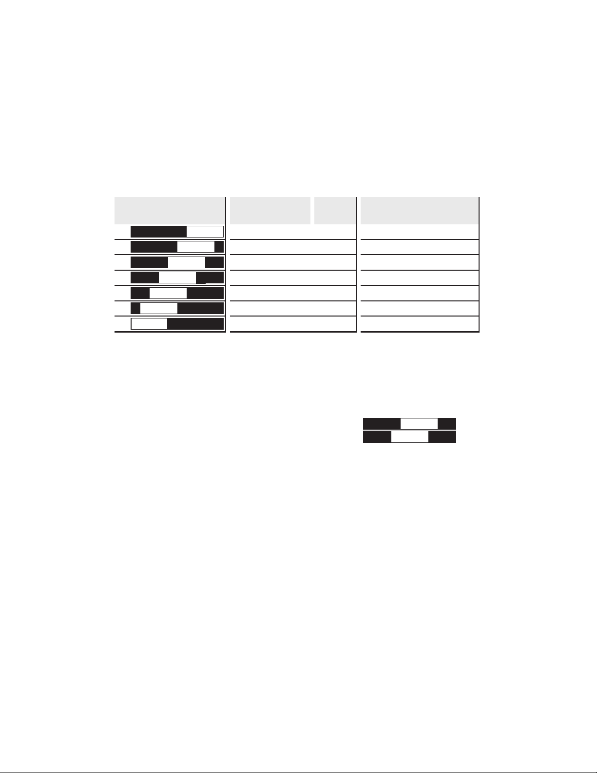
Setting the pre-selection counter / the pulse value (ImPS-value)
The settable values (0.001m³ bis 1 000000 m³) are presented programm-internally by a 10-figure display. The display shows a
4-figure excerpt (the 4 highest-value figures) of the set number.
Presentation range,
example
1 0.001 ... 9.999 1 ... 9999 Norm litres
00 0 0 0 0
2 10.00 ... 99.99 10 ... 99,99 Nm³
0 0 0 0 0 0
3 100.0 ... 999.9 100 ... 999,9 Nm³
0 0 0 0 0 0
4 1000 ... 9 999 1000 ... 9 999 Nm³
0 0 0
5 10.00 ... 99.99 10 000 ... 99990 Nm³
0 0 0 0 0 0
6 100.0 ... 999.9 100 000 ... 999900 Nm³
0 0 0 0 0 0
7 1000 1000 000 Nm³
.3
3.021
0001
.0
30
1
.2
02 1
.3
3.021
0 0
3021
.0
02 1
Display in Nm³ LED 10³
00000
value
ON
ON
ON
Figures not displayed are always switched to zero. When changing
to the next-highest presentation range, the lowest-value figure is
pushed to the right out of the display window and switched to zero,
independently of its previous value.
Example: Change from presentation range 3
to presentation range 4
0 0 0 0 0 0
0 0 0 0 0
999
1000
.9
.0
Setting procedure:
1. Ensure that OU1 is set to ImP (→ page 16).
2. Press the Mode/Enter button until ImPS is displayed.
3. Press and hold down the Set button. The current number value is
displayed flashing for 5 s, after which highest-valued of the 4 figures becomes active (figure flashes, can be altered).
4. Set the desired value as shown in the table on the following page.
First select the desired presentation range (1, 2, 3 ...), see above.
Then set the number from left (highest-value figure) to right
(lowest-value figure)..
5. Briefly press the Mode/Enter button (confirmation) when you have
set all 4 figures.
54
Find Quality Products Online at: [email protected]
www.GlobalTestSupply.com
Page 25
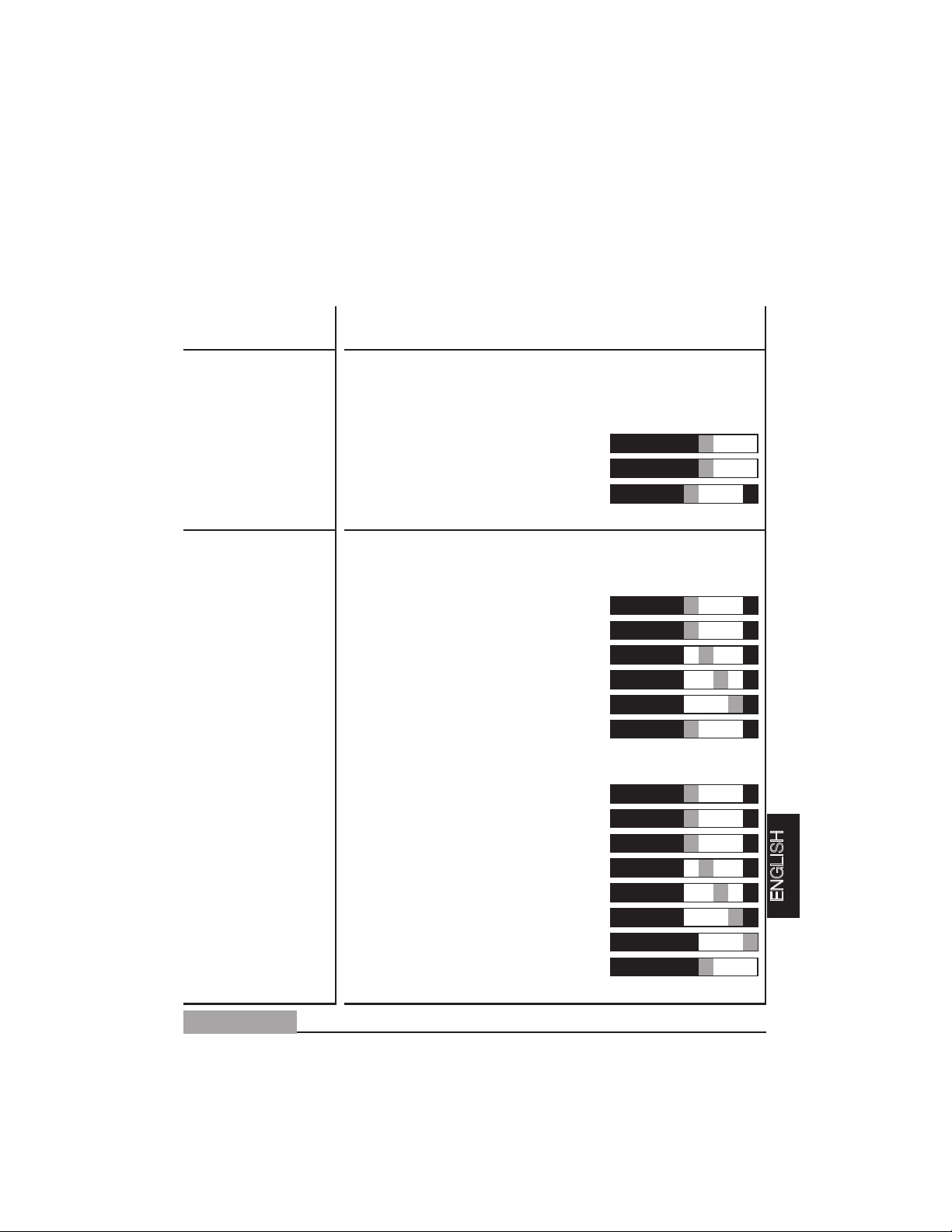
Note:
If you hold the Set button down, the display runs through all ranges;
after the final value (1000+LED 10³) it returns to the starting value
0.001. Briefly release the button. You can then start the setting again.
Single press of Set
button.
Press and hold
down Set button
Press no button for
3 seconds
.
The flashing position is increased. After 9 follow 0 - 1 2 etc. The presentation range is not left.
The flashing position is increased. After 9 follows 0 and
the higher-value position (left) becomes active.
If position 1 is altered in this way, the display changes
to next highest presentation range.
Example:
Set button held
down
(Change from range 1 to range 2).
The following position (right) flashes. If the fourth position flashes for 3 sec without change, position 1 becomes active again, if it has a value > 0.
Example:
Set button pressed 1x
no button pressed, after 3 s
after 3 s
after 3 s
after 3 s
If position 1 has the value “0”, the display changes to
the next lower presentation range..
Example:
Set button pressed 1x
Set button pressed 1x
no button pressed, after 3 s
after 3 s
after 3 s
after 3 s
after 3 s
(Change from range 2 to range 1).
00 0 0 0 0
00 0 0 0 0
0 0 0 0 0 0
0 0 0 0 0 0
0 0 0 0 0 0
0 0 0 0 0 0
0 0 0 0 0 0
0 0 0 0 0 0
0 0 0 0 0 0
0 0 0 0 0 0
0 0 0 0 0 0
0 0 0 0 0 0
0 0 0 0 0 0
0 0 0 0 0 0
0 0 0 0 0 0
00 0 0 0 0
00 0 0 0 0
23
8
.1
23
9
.1
1
20
.1
8
31
.2
9
31
.2
19
3
.2
31 9
.2
31 9
.2
9
31
.2
8
31
.2
9
31
.2
31
0
.2
3
10
.2
31 0
.2
31 0
.2
3 0
1
.2
30
1
.2
ENGLISH
Marked in grey = flashing position.
55
Find Quality Products Online at: [email protected]
www.GlobalTestSupply.com
Page 26
Operation / Maintenance
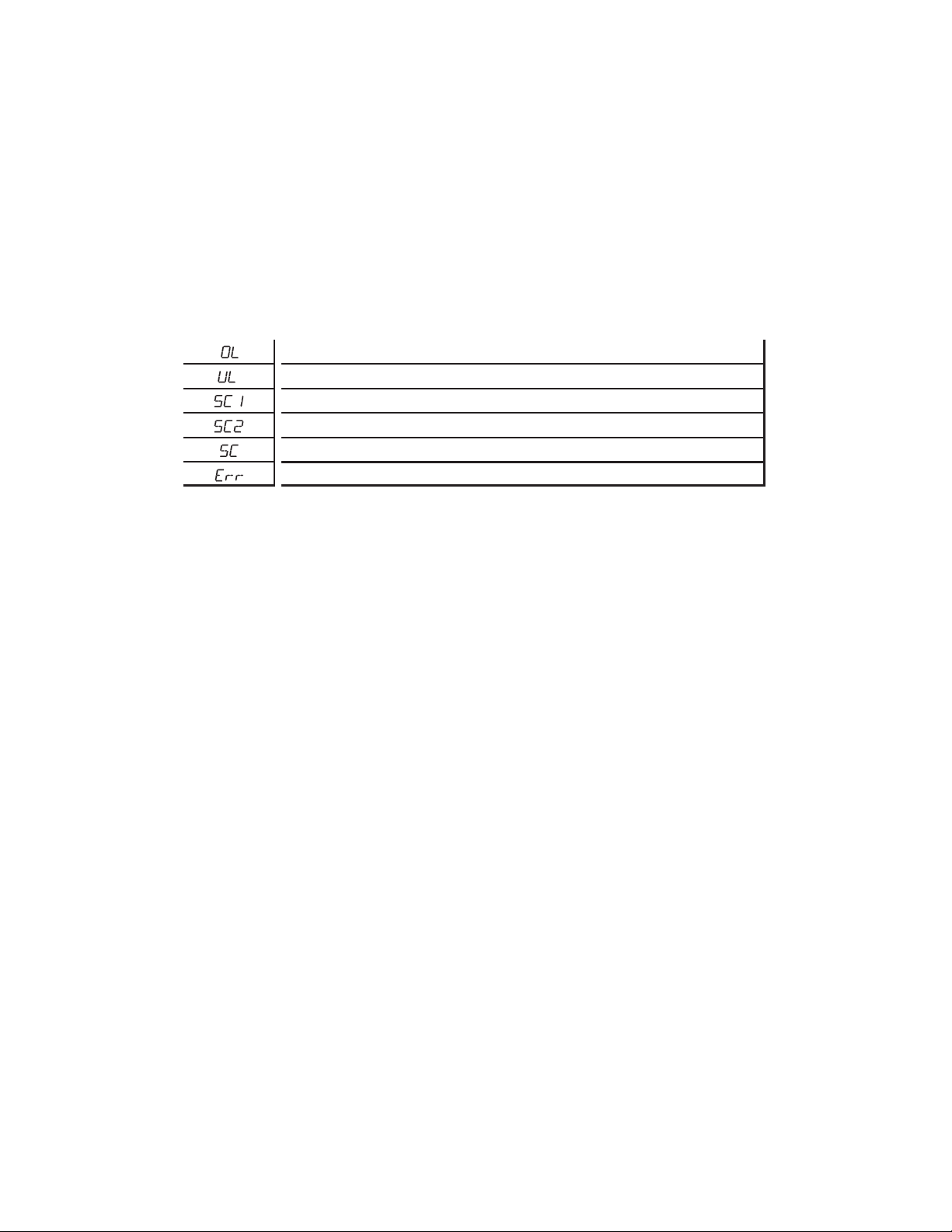
Dysfunction displays
Meas. value > 120% of meas. range scale value cf. page 21.
Meas. value < starting value of meas. range cf. page 21.
Flashing: Short circuit in switch output 1.*
Flashing: Short circuit in switch output 2.*
Flashing: Short circuit in both switch outputs.*
Flashing: Malfunction of measurement probe.
*The affected output is switched off, as long as the short circuit carries on.
These warnings are shown even when the display is switched off.
The instrument is maintenance-free in media that do not adhere to
the measurement probes.
• As necessary, check the measurement probes optically for deposits.
• If necessary, clean them at certain intervals. Use a suitable cleaning liquid (e.g. alcohol solution).
• Avoid mechanical damage to the measurement probes.
Flawless operation and adherence to measurement accuracy can
only be guaranteed if the ambient conditions stated in the “Technical
Data” on page are complied with. Pay special attention that the
maximum pressure range, the measuring range, the humidity range
and the acceptable ambient temperature are not exceeded.
To monitor compressed air humidity, we recommend the pressure
dewpoint measurement transmitter testo 6740.
• Excessively high humidity leads to lower accuracy, not to
damage.
56
Find Quality Products Online at: [email protected]
www.GlobalTestSupply.com
Page 27
Technical Data
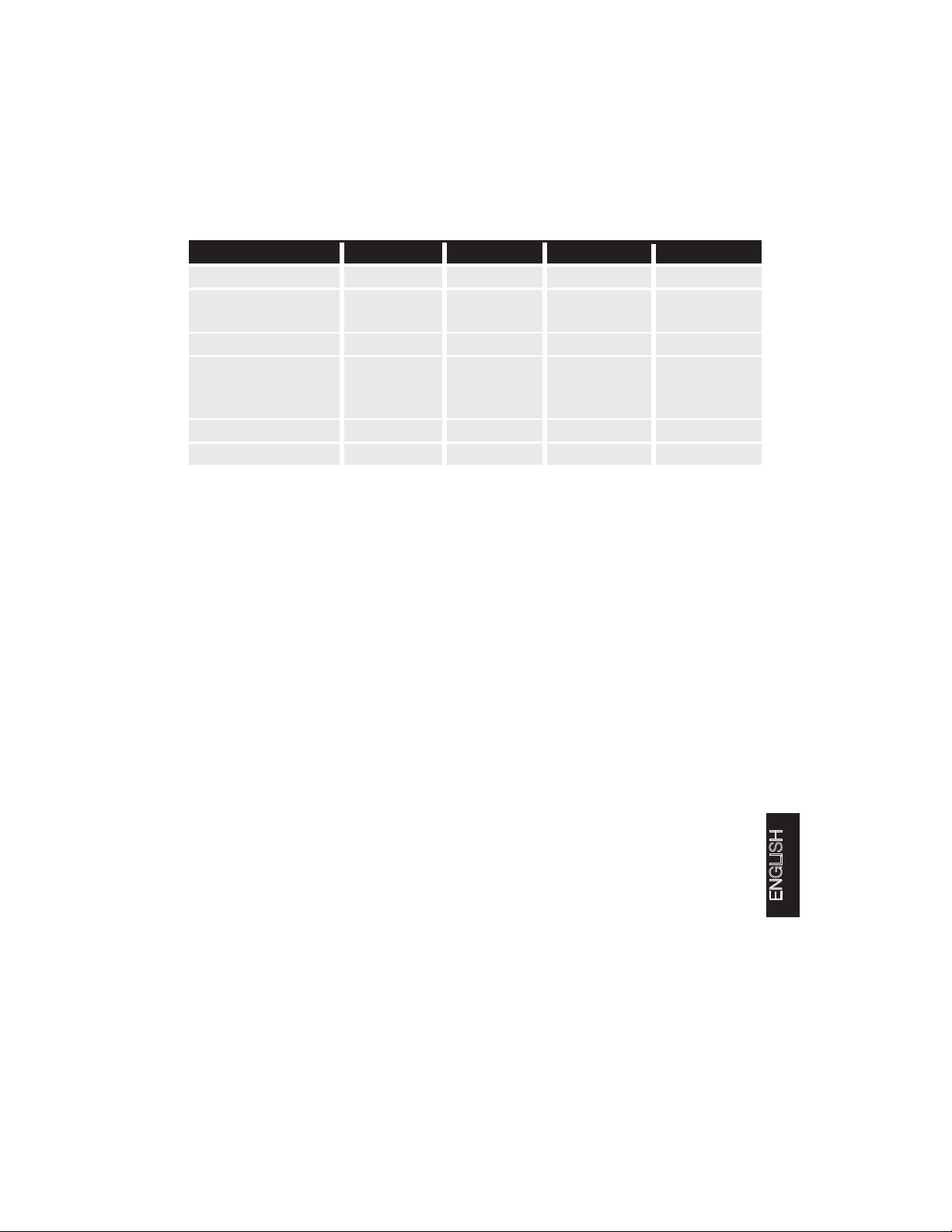
testo 6441 testo 6442 testo 6443 testo 6444
Pipe diameter DN 15 (½”) DN 25 (1”) DN 40 (1½”) DN 50 (2”)
Meas. range (1:300) 0.25... 0.75... 1.3... 2.3...
75 Nm3/h 225 Nm3/h 410 Nm3/h 700 Nm3/h
Max. display value 90 Nm3/h 270 Nm3/h 492 Nm3/h 840 Nm3/h
Meas. pipe: DN 15, R ½ DN 25, R1 DN 40, R 1½ DN 50, R2
DN/thread Stainless steel Stainless steel Stainless steel Stainless steel
(both sides)/material 1.4301 1.4301 1.4401 1.4401
Meas. pipe length 300 mm 475 mm 475 mm 475 mm
Weight 0.9 kg 1.1 kg 3.0 kg 3.8 kg
General
Sensor ................................................................................................Thermal, glasscoated sensor
Accuracy................for compressed air quality classes 141: ± 3% of meas. val. ±0.3% of fin. val.
for compressed air quality classes 344: ± 6% of meas. val. ±0.6% of fin. val.
Reaction time ............................................................................<0.1 s (for damping parameter = 0),
delayable via operation menu (0s to 1s)
Temperature display ............................................................0...60°C, measurement inaccuracy ± 2K
Display, operation ........................................4figure, alphanumeric display, two operating buttons
Operation menu, LED (4x green for phys. units,
3x yellow for “Display x 1.000” or switch status)
Display units ................................................................................................Nm3/h, Nl/min, Nm3, °C
Electrical connection ......................................M 12x1plug, loadable to 250 mA, short circuitproof
(synchronized), reverse polarityproof, overloadproof
Voltage supply..............................................................19 to 30 V DC, current consumption <100mA
Output signals ..............................4 combinations are parameterable via operation menu, cf. page 8
Pulse output......................................................Consumption counter, value 0.001 to 1,000,000 m3,
Pulse length 0.02 s to 2 s, 24 V DClevel
Analog output................................................4...20mA (3wire), max. load 500 Ohm, freely scalable
between 0 to end of measuring range
Switch output............................2 switch outputs (pnp) parameterable, each with max 19 to 30 V DC
2 x 250 mA loadable, switch status is displayed via 2 LED
dependent on either norm volume flow or consumption quantity
Process conditions ............................................0...+60 °C, PN max 16 bar, rel. humidity < 90 %RH,
air quality ISO 8573: recommended classes 141
Ambient temperature..........................................................................................................0...+60 °C
Storage temperature......................................................................................................25...+85 °C
Media contact ........................................Materials stainless steel 1.4301 or 1.4401, PEEK, polyester,
viton, anodized aluminium
Housing..........................................................................................PBT GF 20%, zinc diecast, IP65/III
EMC ..................................................................................................In accordance with 2014/30 EU
ENGLISH
57
Find Quality Products Online at: [email protected]
www.GlobalTestSupply.com
Page 28

Ordering data
Description Order No.
testo 6441 Compressed air counter DN 15 ........................................................................0555 6441
testo 6442 Compressed air counter DN 25 ........................................................................0555 6442
testo 6443 Compressed air counter DN 40 ........................................................................0555 6443
testo 6444 Compressed air counter DN 50 ........................................................................0555 6444
Electrical connection wire
length 5 m, with M12 socket ............................................................................................0699 3393
testo 542AC process display,
2 relay outputs (to 250 V AC / 300V DC, 3A,
Current supply 90...260 V AC)............................................................................................5400 7553
testo 547AC process display,
2 relay outputs (to 250 V AC / 300 V DC, 3A,
Current supply 90...260 VAC), with RS485output
for online monitoring and with totaliser..............................................................................5400 7555
Mains unit (desktop) 100...240 VAC / 24 VDC (350 mA) ..................................................0554 1748
Mains unit (rail mounting)
90...264 V AC / 24 V DC (3 A)............................................................................................0554 1749
ISO calibration at 5 measuring points, to 250 Nm
for testo 6441 / 6442 ........................................................................................................0520 0174
DAkkS calibration at 5 measuring points, to 250 Nm
for testo 6441 / 6442 ........................................................................................................0520 0274
ISO calibration at 5 measuring points, to 1600 Nm
for testo 6443 / 6444 ........................................................................................................0520 0184
DAkkS calibration at 5 measuring points, to 1600 Nm
for testo 6443 / 6444 ........................................................................................................0520 0284
3
/h
3
/h
3
/h
3
/h
58
Find Quality Products Online at: [email protected]
www.GlobalTestSupply.com
Page 29
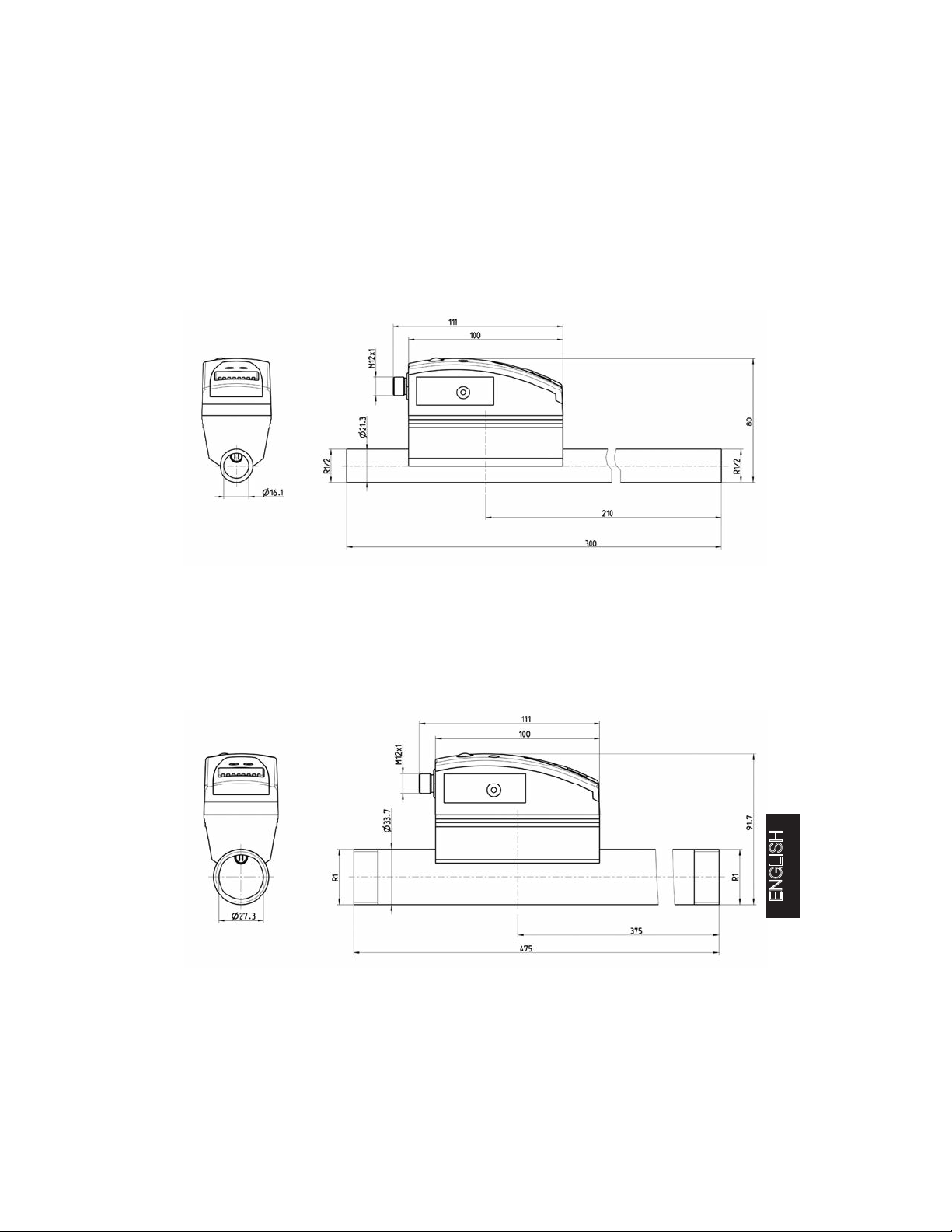
testo 6441
testo 6442
Dimensional drawing
ENGLISH
59
Find Quality Products Online at: [email protected]
www.GlobalTestSupply.com
Page 30
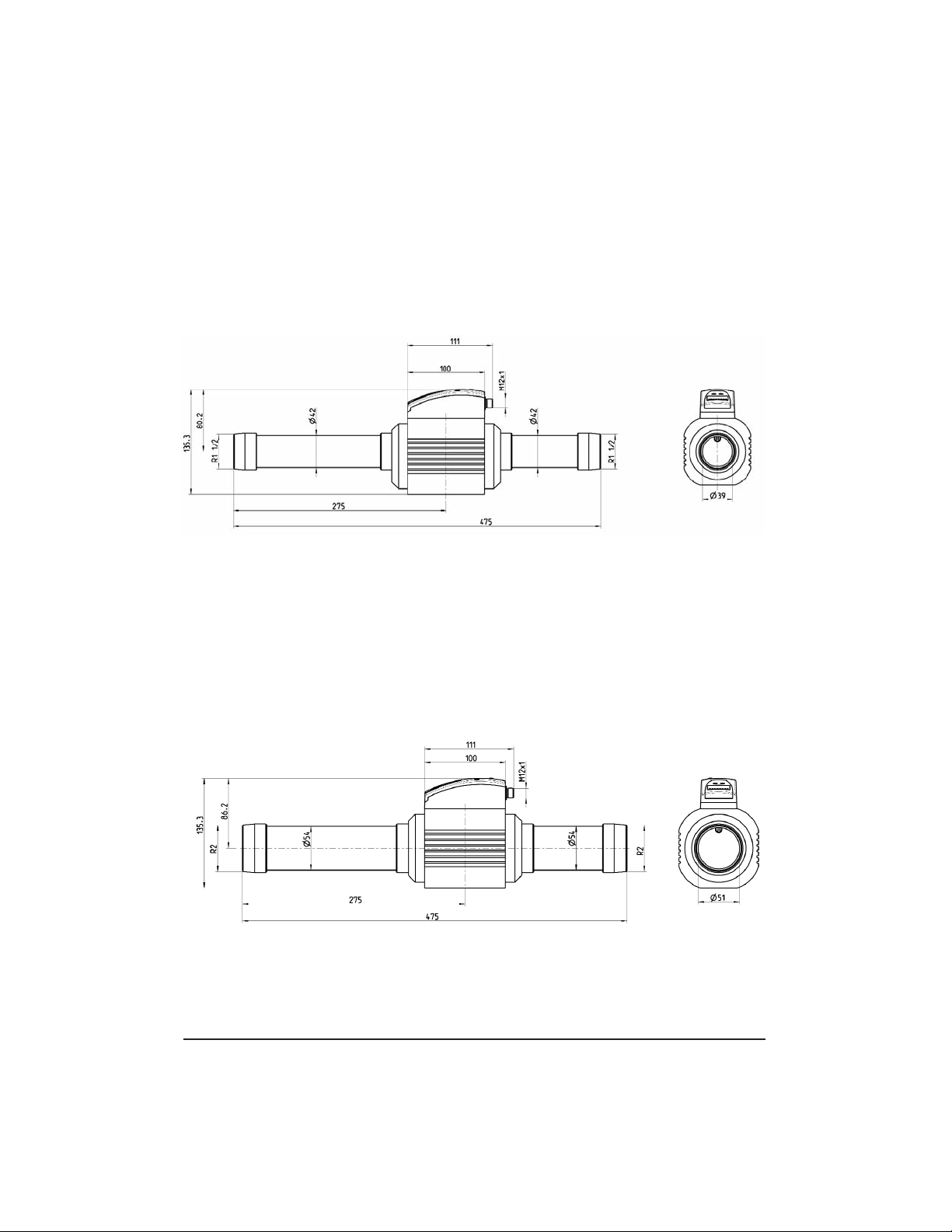
Dimensional drawing
testo 6443
testo 6444
60
Find Quality Products Online at: [email protected]
www.GlobalTestSupply.com
 Loading...