

Page 1
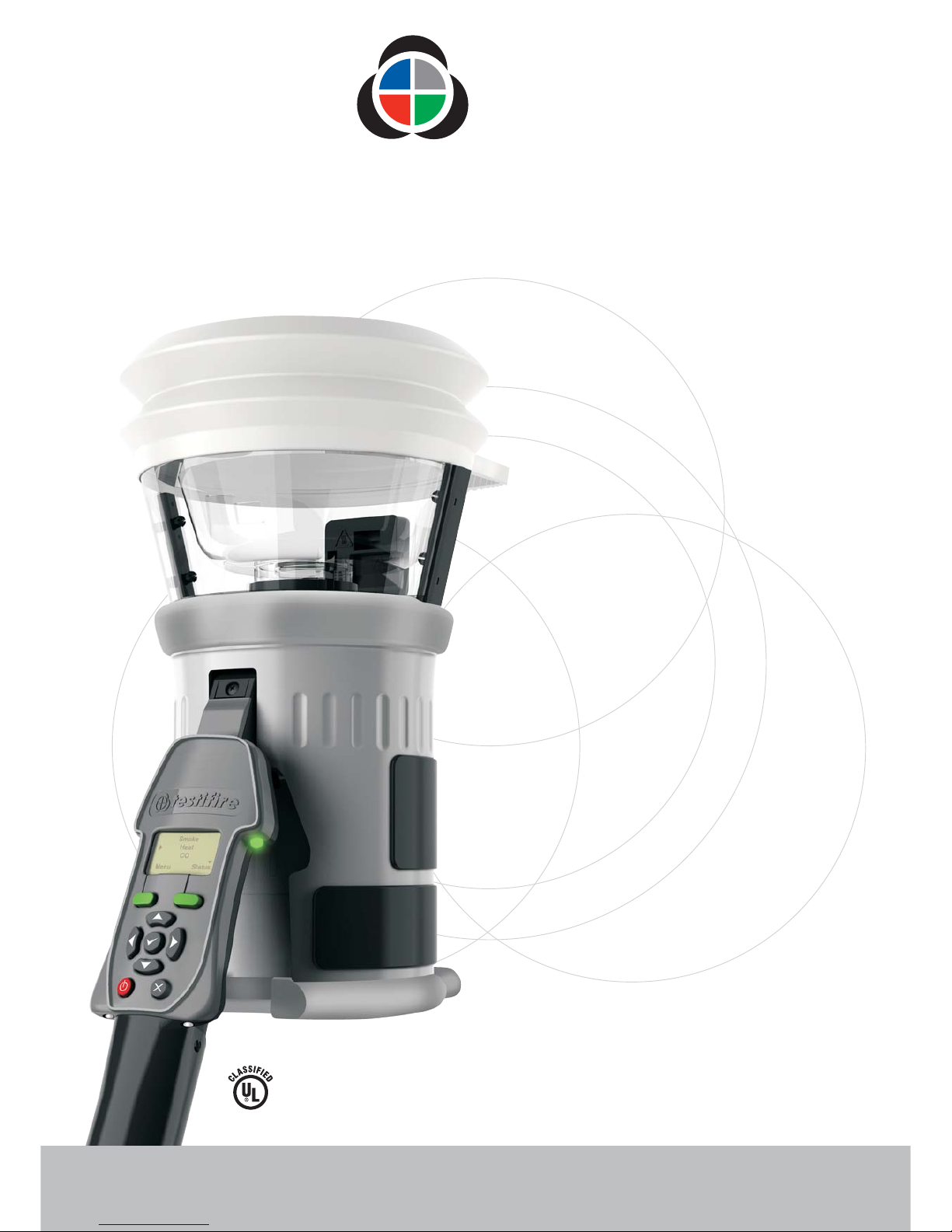
Quick Start Guide
MULTI-STIMULUS DETECTOR TESTER
testifire
®
www. .comtestifire
SIGNALING
Multi-Detector Test
Apparatus as to Verification
of Detector Functional
Operation Only
77TL
Page 2
Preparation For Use
Quick Start Guide testifire
®
to MULTI STIMULUS DETECTOR TESTER
www. .comtestifire
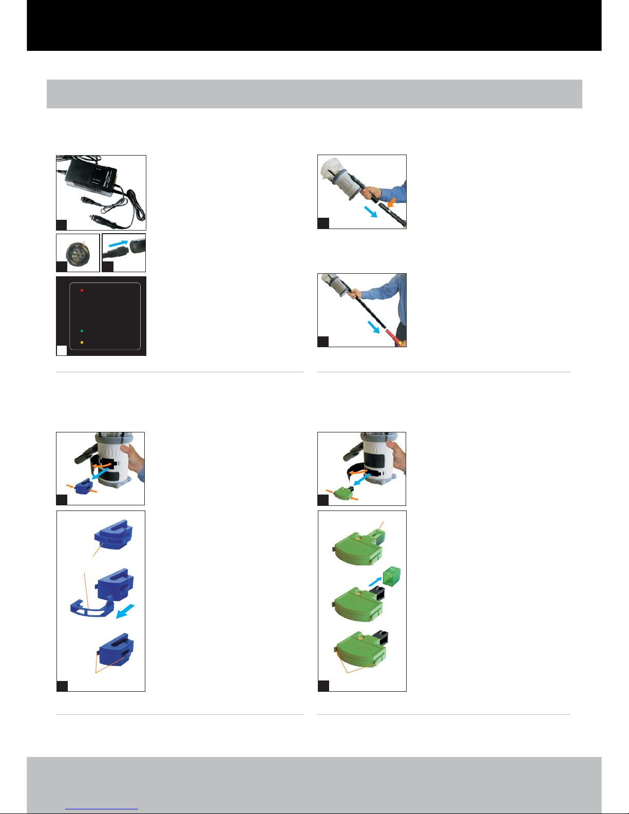
1. Charging the Battery Baton 2. Inserting the Battery Baton
3. Removal & Replacement of
Smoke Capsules
(Testifire 1000 & 2000 series)
4. Removal & Replacement
of CO Capsules
(Testifire 2000 series only)
Power
Trickle charge
Fast charge
ProductCode: Solo 725-001
LL34271-1
Battery Charger for:
Solo - Testifire - Scorpion
™
®®
Locking Ring
l
l
l
l
l
The charger can be connected to
a mains power outlet or a 12 volt
vehicle socket ( ). When connected,
the red Power LED will illuminate.
Connect the Battery Baton to the
charger and turn the locking ring
(&).
The yellow Fast Charge LED will
illuminate ( ).
Charge times vary but can be
75-90 minutes when charging a
fully discharged Battery Baton.
When fully charged, the charger
will switch to Trickle Charge and
the green LED will illuminate ( ).
Use only NiMH Battery
Batons with Testifire.
1
23
4
4
Note:
1
2
3
4
l
l
To insert the Battery Baton, hold
the Testifire head unit by the
handle and depress the upper
spring button on the Battery Baton.
Align the button with the location
hole in the handle and push the
Battery Baton into the handle until
the button springs up through the
location hole ( ).
Insert the other end of the Battery
Baton into the Solo access pole and
depress the lower spring button.
Align it with the location hole and
push the Battery Baton further into
the pole until the button springs up
through the hole ( ).56
Spring Clips
Spring Clip
Protector
C
Removal:
7
Note:
Replacement:
8
Release the upper access cover
( ) on the body of the Testifire by
opening it from the right hand side.
Testifire 1000 series units
only have one access cover.
Squeeze the two clips of the
used capsule and gently pull the
capsule out.
Remove the capsule from its outer
carton and Anti-Static bag.
Remove the spring clip protector
cap from the new capsule ( ).
Holding the capsule by the spring
clips with the label on the
underside, carefully insert the new
capsule into the capsule port. Push
it into position, ensuring that the
clips spring out positively on both
sides of the capsule.
Close the access cover securely.
l
l
l
l
l
l
A
B
C
A
Spring Clips
Tip Protector
Removal:
9
Replacement:
10
Only replace the CO capsule when
it is empty. Turn Testifire off for five
minutes to allow the capsule to cool
down before removing it.
Release the lower access cover
( ) by opening it from the right
hand side.
Squeeze the spring clips on each
side and gently pull the capsule out.
Do not touch the tip of the CO
capsule as it may be hot.
Remove the capsule from its carton
and Anti-Static bag.
Remove the tip protector ( ).
Hold the capsule by the spring clips
with the label uppermost. Carefully
insert into position, ensuring that
the clips spring out positively on
both sides.
Close the access cover securely.
l
l
l
l
l
l
l
l
D
E
F
D
8
10
F
B
B
E
E
F
A
B
B
E
E
D
5
6
7
9
Page 3
MULTI-STIMULUS DETECTOR TESTER
testifire
®
www. .comtestifire
11
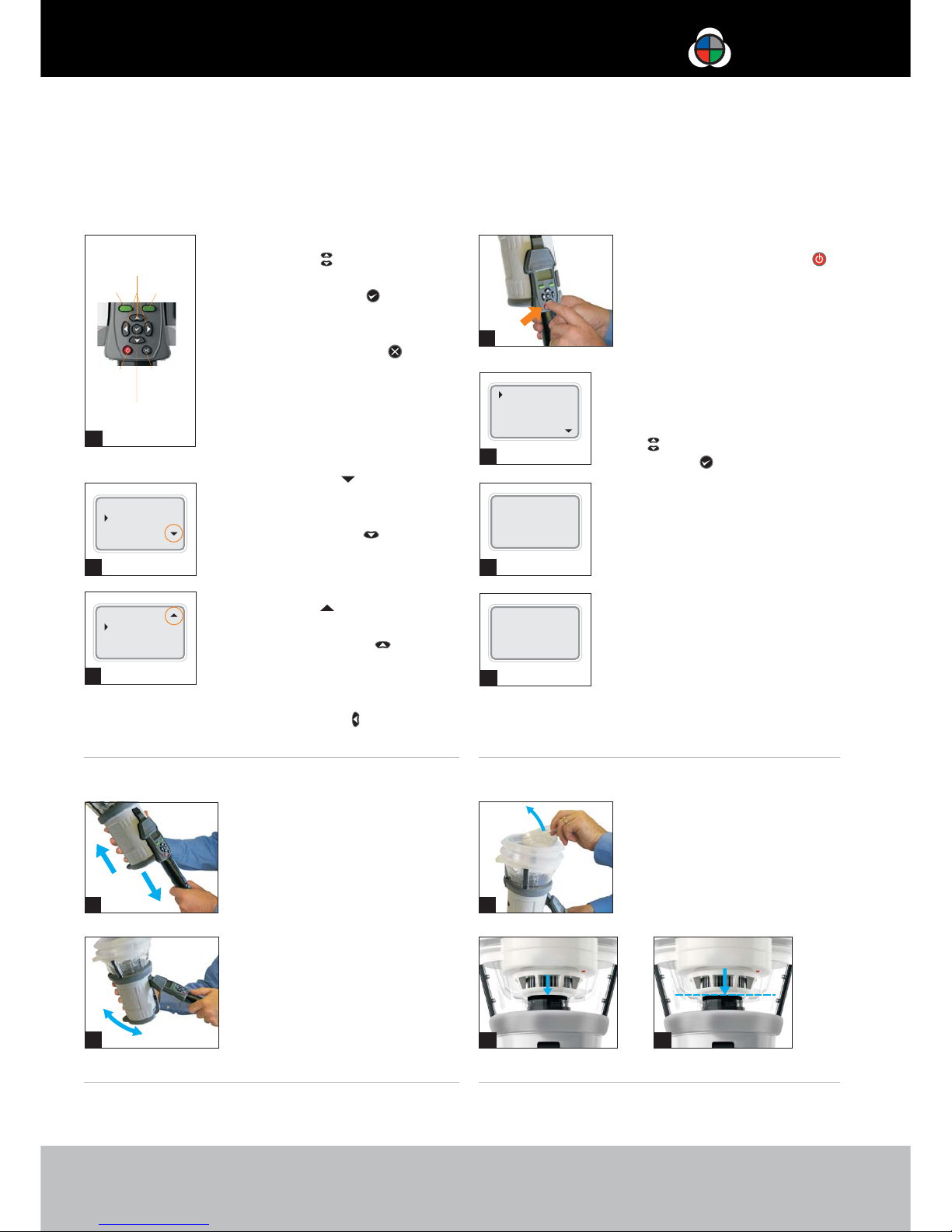
5. Using the Menus
7. Adjusting the Head Angle
13
12
Menu Key
ON/OFF
Key
18
19
Heat
CO
Clear
Menu Status
Smoke
Heat
CO
Menu Status
Enter Key
Menu
Navigation
Keys
Keypad
Escape Key
Status Key
l
l
l
l
l
Using the ‘UP’ and ‘DOWN’ menu
navigation keys ( ), you can move
the cursor through the ‘MAIN’ menu.
Press the ‘ENTER’ key to select
stimuli from the ‘MAIN’ menu.
Pressing the ‘ESCAPE’ key goes
back to the ‘MAIN’ menu, or when a
test sequence has been programmed
and the ‘MAIN’ menu is displayed,
the ‘ESCAPE’ key will cancel the
programmed test sequence.
A ‘DOWN’ arrow on the bottom
right of the ‘MAIN’ menu indicates
more options are available below.
Use the ‘DOWN’ key on the
keypad to move down through the
menu. ( ).
The ‘UP’ arrow on the ‘MAIN’
menu indicates more options available
above. Use the ‘UP’ key on the
keypad to move up through the menu
().
Press the ‘LEFT’ key on the keypad
to go back one menu level.
11
12
13
l
l
Correct head angle adjustment
is important. The detector should
touch the base of the inner clear
cup ( ).
To adjust the head unit hold the
body ( ) and, pulling gently
against the spring, angle the head
unit away from the Battery Baton
( ). The head unit will lock and
remain in that position for testing.
22
18
19
6. Turning the Unit On
8. Testing High Profile Detectors
15
16
17
21
14
20
English
Select Cancel
Preparing for use
Please wait
English
Français
Deutsch
Español
l
l
l
l
To turn the unit on, press and
hold the red ‘ON-OFF key’
for 2 seconds ( ). The ‘Status’
LED will flash slowly green to
indicate that the unit is in
‘STANDBY’ mode.
The first time the unit is poweredon you will be prompted to select
the operating language for your
region. Use the ‘UP’ and ‘DOWN’
keys to navigate and use the
‘ENTER’ key to select your
language ( ).
This will display a confirmation
screen ( ). Press the ‘MENU’ key
to confirm or the ‘STATUS’ key to
cancel. The ‘MAIN’ menu will be
displayed.
After long periods of non-use or
when a Smoke Capsule has been
replaced, the unit will self-prime
at power-on. The ‘Preparing for
use Please wait’ message will be
displayed for a short period ( ).
14
15
16
17
l
When testing high profile
detectors, remove the inner
clear cup. Place your finger in
the cut-out and carefully lift out
the inner cup ( ). This will
allow the detector to touch
the platform ( ).
20
21
22
Page 4
Testing a Detector
MULTI-STIMULUS DETECTOR TESTER
testifire
®
www. .comtestifire
Smoke
Heat
CO
Menu Status
l
l
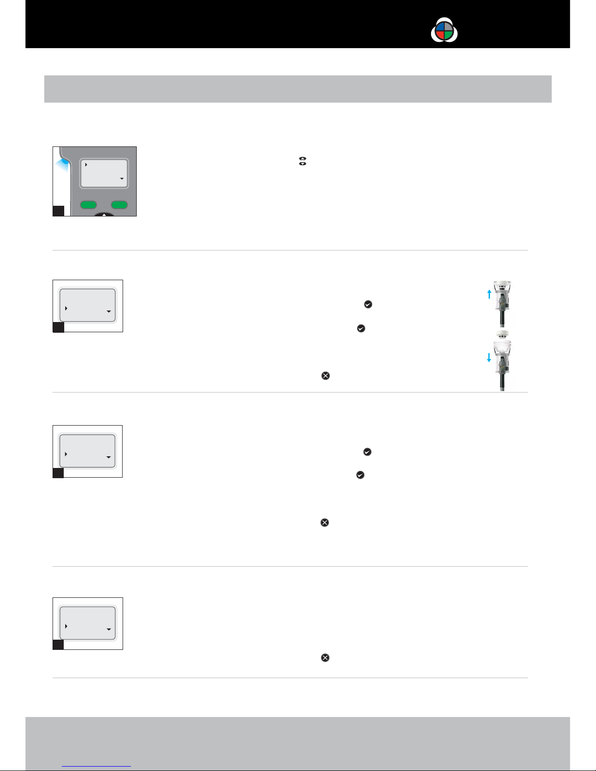
To carry out a simple, single stimuli
test, use the UP and DOWN keys
on the keypad to highlight the stimul
required ).
Raise the Testifire head unit up to the
detector to be tested, and place it
centrally over the detector.
‘’ ‘ ’
us
e.g. ‘Smoke’ (23
23
1. How to Perform a Test
N:ote22It is very important that the detector under
test is in the correct position ). Ideally, the
bellows should seal against the ceiling surface.
(
24
In this example, ‘Smoke’ and ‘Heat’ are selected as a
simultaneous test ( ).
Move the cursor to ‘Smoke’ and press the ‘ENTER’ key
‘ ’ will be displayed alongside ‘Smoke’.
Move the cursor to ‘Heat’ and press the ‘ENTER’ key
‘ ’ will be displayed alongside ‘Heat’. Press ‘ENTER’
once more to display ‘ ’ alongside ‘Heat’.
Repeat the above as required for additional stimuli.
To delete a test setup, use the ‘ESCAPE’ key .
1
2
1
l
l
l
l
2. Simultaneous Testing (selected tests at the same time)
In this example, ‘Smoke’, ‘Heat’ and ‘CO’ are selected as a
sequential test ( ).
Move the cursor to ‘Smoke’ and press the ‘ENTER’ key
‘ ’ will be displayed alongside ‘Smoke’.
Move the cursor to ‘Heat’ and press the ‘ENTER’ key
‘ ’ will be displayed alongside ‘Heat’.
Move the cursor to ‘CO’ and press the ‘ENTER’ key
‘ ’ will be displayed alongside ‘CO’.
To delete a test setup, use the ‘ESCAPE’ key .
25
1
2
3
l
l
l
l
In this example, ‘Smoke’ and ‘Heat’ are combined as a
simultaneous test followed by ‘CO’ ( ).
‘Heat’ and ‘Smoke’ can be combined as the first operation,
followed by a ‘CO’ test. you will need to lower the
head unit between each test.
To delete a test setup, use the ‘ESCAPE’ key .
26
Note:
l
l
3. Sequential Testing (selected tests, one after another)
4. Combined Simultaneous and Sequential Testing
Smoke 1
Heat 1
CO
Menu Status
Smoke 1
Heat 2
CO 3
Menu Status
Smoke 1
Heat 1
CO 2
Menu Status
1. Programme the tests: Smoke 1
Heat 1
2. Raise Testifire
over the detector:
‘Smoke’ and ‘Heat’
are tested at the
same time as test ‘ ’.1
3. Lower Testifire
from the detector:
The test is completed
and ready to test another
detector in the same way.
1. Programme the tests: Smoke 1
Heat 2
CO 3
The test is completed and ready to
test another detector in the same way.
Lower Testifire:5.
2. Raise Testifire over the detector:
‘Smoke’ is tested as test ‘ ’.1
3. Lower for 2-10 seconds, then
raise Testifire again:
‘Heat’ is tested as test ‘ ’.2
4. Lower for 2-10 seconds, then
raise Testifire again:
‘CO’ is tested as test ‘ ’.3
Using these methods, you can
programme Testifire to combine tests
and continue in sequence.
‘Clear’ (clearing) can also be
selected in any of the above operations.
Note:
24
25
26
l
As the detector enters Testifire, the infrared beam
is interrupted by the body of the detector
chosen test indicated by the LED
flashing faster.
and the
will begin, ‘Status’
In this example ‘Smoke’ and ‘Heat’ are
tested together as test ‘ ’ and then
‘CO’ is tested as test ‘ ’.12
Page 5
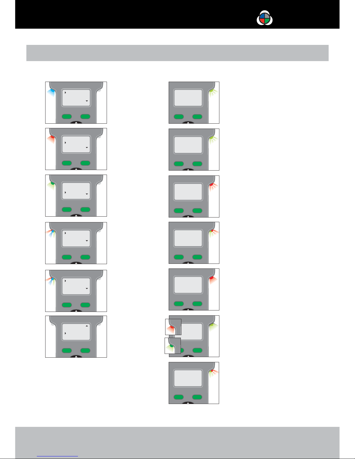
Indicating LED Reference Chart
MULTI-STIMULUS DETECTOR TESTER
testifire
®
www. .comtestifire
‘Test Type’ LED ‘Status’ LED
Blue Solid
Smoke Test in progress
Red Solid
Heat Test in progress
Green Solid
CO Test in progress
Not Illuminated
Clearing mode in
operation
Red Flashing
(slow red flashing in ‘STANDBY’ mode
or fast red flashing in operation)
Battery needs charging Testifire still operational
Red Solid
-Error see message on display
(refer to User Manual for a complete
list of Indicating LED Error Messages)
Alternating Red/Green
Flashing
‘TIME OUT’ Indication (after 2 minutes
of continuous testing on one stimulus
or combination of stimuli)
Green Slow Flashing
‘STANDBY’ Mode
Green Fast Flashing
‘OPERATIONAL’ Mode
(test in progress)
Red/Blue/Green
Alternating
Smoke, Heat and CO
test in progress at the
same time
(Simultaneous Testing)
Blue Solid/ then
Red/Green Alternating
‘Test in progress’ portion
of Smoke, then Heat & CO
combined testing
(Sequential Testing)
Alternating Red and Green fast flashes
with long gaps
"CO Cooling phase" - Indication after a CO
test has been carried out. Further CO test
cannot be carried out until Status LED shows
"STANDBY" mode.
Green Solid
CO Cooling
(Status LED ‘blips’ red or green.
The next test will start when the
capsule has cooled sufficiently)
Smoke
Heat
CO
Menu Status
Smoke
Heat
CO
Menu Status
Smoke
Heat
CO
Menu Status
Heat
CO
Clear
Menu Status
Smoke 1
Heat 1
CO 1
Menu Status
Smoke 1
Heat 2
CO 2
Menu Status
Page 6
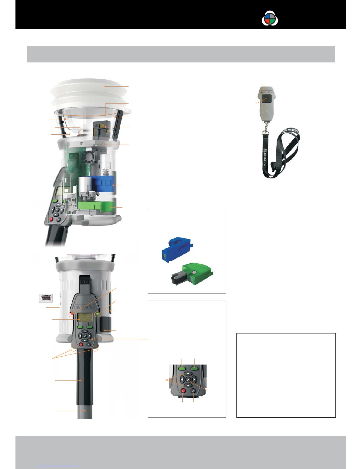
Identification of Parts
MULTI-STIMULUS DETECTOR TESTER
testifire
®
. Inner Clear Cup
. Platform
. Clear Cup
. Bellows
. RFID Antenna**
. Infrared Beam
. Main Duct for Heat, Smoke and CO*
. Testifire 100 RFID Bluetooth®Module**
. Smoke Capsule TS3
. CO Capsule TC3*
. USB Port (on rear of unit)
. User Interface Display (LCD)
. ‘Test Type’ LED
. ‘Status’ LED
. Smoke Capsule Access Cover
. CO Capsule Access Cover*
. Adjustable Handle
. Battery Baton
. Infrared Remote Control Receivers
* Depending on model specification ** Future option
1
2
3
4
5
6
7
8
9
10
11
12
13
14
15
16
17
18
19
A
B
DC
H
G
F
E
User Interface Keypad
Menu Key
Status Key
Menu Navigation Keys
Enter Key
ON/OFF Key
Escape Key
C
D
E
F
G
H
Replacement Capsules
Testifire Smoke Capsule TS3
Testifire CO Capsule TC3*
A
B
www. .comtestifire
11
1
3
18
17
12
19
2
Testifire 2000 Illustrated
BB
AA
14
13
16
15
testifire
Infrared Remote Control
Operation Indicator LED
Contol Button
AA
BB
9
10
7
8
4
5
6
®
25
Infrared Remote Control
Generation of test stimuli starts when
Testifire is positioned over a detector and
remote controls are not generally required.
Certain detectors (such as those with virtual
chambers) have no physical features to cause
stimuli generation to start. The optional
infrared remote control can be used to
initiate the test procedure in such situations.
CAUTION Please refer to
your User Manual and take
clearnote of all warnings and
cautions before using your
Testifire.
1
General Safety Information
Testifire has no userserviceable parts. Do not
disassemble. Refer to the
manual for Service and
Support information.
Page 7

As our policy is one of continuous improvement, details of products
described within this publication are subject to change without
notice. All information provided here is believed to be correct at the
time of going to press. Every effort has been made to ensure the
accuracy of information which is provided in good faith but nothing
contained herein is intended to incorporate any representation or
warranty, either express or implied or to form the basis of any legal
relations between the parties hereto, additional to or in lieu of such
as may be applicable to a contract of sale or purchase.
detectortesters
testing technology from No Climb
www. .comdetectortesters
No Climb Products Ltd
Edison House
163 Dixons Hill Road
Welham Green
Hertfordshire AL9 7JE
United Kingdom
Tel: +44 (0) 1707 282 760
Fax: +44 (0) 1707 282 777
GB-LI32156-3
 Loading...