


Forced Air Ovens
Operation and Service Manual
TestEquity LLC
6100 Condor Drive
Moorpark, CA 93021
Support: 877-512-3457 Toll Free
805-480-0638
Corporate: 800-732-3457
805-498-9933
http://www.testequity.com
FS Series
Copyright © 2003-2015 TestEquity LLC Rev. 1.4, Oct. 13, 2015


Table of Contents
Chapter 1 – Safety Instructions ________________________________________________ 1-1
Introduction ____________________________________________________________________ 1-1
Safety Notices ___________________________________________________________________ 1-1
Chapter 2 – Receiving and Installation __________________________________________ 2-1
Inspection ______________________________________________________________________ 2-1
Return Shipment ________________________________________________________________ 2-1
Installation______________________________________________________________________ 2-1
Power Requirements ____________________________________________________________________ 2-2
Location _____________________________________________________________________________ 2-2
Lifting / Handling ______________________________________________________________________ 2-2
Leveling _____________________________________________________________________________ 2-2
Initial Burn-In _________________________________________________________________________ 2-2
Initial Cleaning ________________________________________________________________________ 2-2
Chapter 3 – Operation _______________________________________________________ 3-1
Front Panel Controls _____________________________________________________________ 3-1
Power Switch _________________________________________________________________________ 3-1
Timer Switch __________________________________________________________________________ 3-1
Overtemperature Protection Thermostat _____________________________________________________ 3-1
Overtemperature Light __________________________________________________________________ 3-1
Timer ________________________________________________________________________________ 3-1
Temperature Controller __________________________________________________________________ 3-1
Heating Light _________________________________________________________________________ 3-1
Operating the Oven ______________________________________________________________ 3-2
Turning the Oven On ___________________________________________________________________ 3-2
Setting the Temperature Controller _________________________________________________________ 3-2
Setting the Overtemp Protection Thermostat _________________________________________________ 3-2
Setting the Timer _______________________________________________________________________ 3-3
Chapter 4 – Maintenance _____________________________________________________ 4-1
Cleaning ________________________________________________________________________ 4-1
Storage _________________________________________________________________________ 4-1
Calibration _____________________________________________________________________ 4-1
Troubleshooting Guide ___________________________________________________________ 4-2
Parts List _______________________________________________________________________ 4-5
Specifications____________________________________________________________________ 4-5
Wiring Diagram _________________________________________________________________ 4-6
Chapter 5 - Warranty ________________________________________________________ 5-1


Chapter 1 – Safety
Chapter 1 – Safety Instructions
Introduction
Follow all CAUTION notices to prevent damage to the chamber or your test sample. Failure to
follow all CAUTION notices may void your warranty. CAUTION may also indicate a
potentially hazardous situation which, if not avoided, may result in minor or moderate personal
injury.
WARNING indicates a potentially hazardous situation which, if not avoided, could result in
death or serious injury.
The safety alert symbol ! precedes a general CAUTION or WARNING statement.
The electrical hazard symbol 2 precedes an electric shock hazard CAUTION or WARNING
statement.
Safety Notices
! WARNING: These units are general purpose air ovens for professional, industrial or
educational use where the preparation or testing of materials is done at
approximately atmospheric pressure and no flammable, volatile or
combustible materials are being heated. These units are not intended for
hazardous or household locations or use.
! WARNING: THIS OVEN IS NOT DESIGNED TO HANDLE COMBUSTIBLE GASSES
AND IS NOT AN EXPLOSION PROOF UNIT. Do not place explosive,
combustible, or flammable materials into the chamber.
! WARNING: Some outgassed byproducts may be hazardous or unpleasant to operating
personnel. If this is the case, the oven exhaust should be positively ventilated
to the outside according to local regulations. A power exhaust is optionally
available which greatly helps under these applications.
! WARNING: Do not operate near noxious fumes.
! CAUTION: Do not place sealed or filled containers in the oven chamber.
! CAUTION: If a mercury thermometer is used for calibration and breakage should occur,
all spilled mercury MUST be completely removed from the chamber before
continuing operation.
! CAUTION: Be sure that the power supply is of the same voltage as specified.
2 WARNING: Do not cut or remove the ground prong from the power cord. Do not use a 2-
prong adapter plug.
TestEquity FS Series Ovens Page 1-1

Chapter 1 – Safety
2 WARNING: Disconnect the unit from its electrical source before proceeding to make any
electrical repairs or replacements.
! CAUTION: This oven is NOT designed for the use in Class I, II, or III locations as defined
by the National Electric Code.
2 WARNING: This oven is not intended, nor can it be used, as a patient connected device.
Page 1-2 TestEquity FS Series Ovens

Chapter 2 – Receiving and Installation
Chapter 2 – Receiving and Installation
Your satisfaction and safety require a complete understanding of this unit. Read the instructions
thoroughly and be sure that all users are given adequate training before attempting to use this
unit. Note: This equipment must be used only for its intended purpose; any alterations or
modifications will void your warranty.
Inspection
The carrier, when accepting shipment, also accepts responsibility for safe delivery and is liable
for loss or damage claims. On delivery inspect for visible exterior damage, note and describe on
the freight bill any damage found and enter your claim on the form supplied by the carrier.
Inspect for concealed loss or damage on the unit itself, both interior and exterior. If any, the
carrier will arrange for official inspection to substantiate your claim.
Verify that your accessory package is complete. All units should have a set of four (4) Leveling
feet, two (2) shelves and eight (8) shelf clips.
Return Shipment
Save the shipping crate and all packaging material until you are sure the oven has not been
damaged and is functioning correctly. If for any reason you must return the unit, contact your
customer support representative for authorization and supply data plate information. Make sure
to include the model and serial number. The service representatives will furnish you with a return
authorization number and address for return. Note: Make sure this return authorization number
appears on the unit packaging and shipping papers. Units returned without proper authorization
may not be accepted at the factory. For information on where to contact customer support please
see the manual cover.
Installation
Local city, county or other ordinances may govern the use of this equipment. If you have any
questions about local requirements, please contact the appropriate local agency. Installation may
be performed by the end user.
This unit is intended for use indoors, at room temperatures between 5° to 40°C (41° to 104°F), at
no greater than 80% Relative Humidity (at 25°C/77°F) and with a supply voltage that does not
vary by more than ±10%. Customer support should be contacted for operating conditions outside
these limits.
TestEquity FS Series Ovens Page 2-1

Chapter 2 – Receiving and Installation
Power Requirements
The power requirements are listed on the oven’s data plate located on the rear. Make sure your
power supply matches that shown on the data plate. VOLTAGE SHOULD NOT VARY MORE
THAN ±10% FROM THE DATAPLATE RATING. These units are intended for 50/60 Hz
application. A separate circuit is recommended to preclude loss of product due to overloading or
circuit failure.
Location
Select a site for the oven which is free from extreme heat, cold or excessive air movement such
as areas near steam radiators, stoves, other ovens, autoclaves, direct sun, heating and cooling
ducts, etc. Avoid high traffic areas which may reduce the accessibility to the oven. Allow at least
2 inches of space between the oven and surrounding walls or partitions which might prevent free
airflow.
Lifting / Handling
These ovens are heavy and care should be taken to use appropriate lifting devices that are
sufficiently rated for these loads. Ovens should only be lifted from their bottom surfaces. Doors,
handles and knobs are not adequate lifting or stabilization. The oven should be completely
restrained from tipping during lifting or transport. All moving parts, such as shelves and trays
should be removed and doors need to be positively locked in the closed position during transfer
to prevent shifting and damage.
Leveling
The oven must sit level and solidly. Leveling feet (supplied) are to be installed in the holes at the
base of the oven. Turn them counterclockwise to raise the level and clockwise to lower the level.
If the oven must be transported, turn the leveling feet in all the way to prevent damage.
Initial Burn-In
It is recommended that the unit go through a “burn-in” process prior to operation. This is to
eliminate the smoking of protective coatings on the element. Read the operating instructions
carefully to understand the operating requirements. To burn-in, turn the OVERTEMP
PROTECTION to maximum and set the TEMPERATURE controller to 200°C. Open the
exhaust vent damper on the top of the oven. Run for a minimum of one hour under ventilation
until smoke dissipates.
Initial Cleaning
The oven’s interior was cleaned at the factory. If you need to clean it further, use a cleaner that is
suitable for your application. Make sure to rinse the cleaned surface with a damp cloth, using
water only, and dry the surfaces with a clean cloth. DO NOT USE chlorine-based bleaches or
abrasives as they will damage the stainless steel surface. DO NOT USE spray cleaners that might
leak through openings and cracks and get on electrical parts or that may contain solvents that will
harm the coatings. A similar periodic cleaning is recommended.
! WARNING: Never clean the unit with alcohol or flammable cleaners with the unit
connected to the electrical supply. Always disconnect the unit form the
electrical service when cleaning and assure all volatile or flammable cleaners
are evaporated and dry before reattaching the unit to the power supply.
Page 2-2 TestEquity FS Series Ovens

Chapter 3 – Operation
B E F
G
l 0 l
Chapter 3 – Operation
Front Panel Controls
0
Power Switch
(A) The POWER switch controls all power to the oven. It must be in the I (ON) position before
any systems are operational. The green light in the switch will be lit when the switch is ON.
Timer Switch
(B) The TIMER switch controls power to the timer circuit. In the O (OFF) position, the oven
heat is controlled with no timed duration. In the I (ON) position, heat is controlled for a timed
interval and then the heat shuts off at the end of that interval.
Overtemperature Protection Thermostat
(C) The OVERTEMP PROTECTION thermostat is an independent controller to protect against
any failure which would allow temperature to rise past the TEMPERATURE controller’s set
point. The adjustment knob points to a relative scale from 0 to 10.
Overtemperature Light
(D) The OVERTEMPERATURE pilot lamp is directly below the OVERTEMP PROTECTION
thermostat. The light will come on when the OVERTEMP PROTECTION is activated and has
taken control of the oven. This pilot lamp should never be on under normal operating conditions.
Timer
(E) The TIMER consists of a digital display, UP/DOWN arrow pads, a RESET pad, a
START/STOP pad and a TIMER ACTIVE light. The TIMER provides the ability to have the
oven maintain heat for a specified period of time.
Temperature Controller
(F) The TEMPERATURE controller consists of digital display and UP/DOWN arrow pads for
entering the temperature set point and for calibration.
Heating Light
(G) The HEATING pilot lamp will be lit whenever the heating elements are energized. It will
cycle on/off when the oven approaches and stabilizes at the desired temperature set point.
TestEquity FS Series Ovens Page 3-1

Chapter 3 – Operation
Operating the Oven
Assure that the electrical power source is properly configured and rated for the oven and plug the
unit cord into the receptacle.
Turning the Oven On
Push the POWER switch to the I (ON) position. Push the timer switch to the O (OFF) position.
The digital temperature display will indicate a temperature value. Turn the OVERTEMP
PROTECTION Thermostat to its maximum clockwise position using a coin or flat head
screwdriver.
Setting the Temperature Controller
To enter the desired set point temperature, press either the UP or DOWN arrow pad once on the
TEMPERATURE digital display. The display will start to blink from bright to dim. While
blinking, the display is showing the temperature set point. You can change the set point by
pushing the UP or DOWN arrow pads to raise or lower the value. If the arrow pads are not
pushed within five (5) seconds, the display will stop blinking and return to read the chamber
temperature. Allow several hours for the temperature to stabilize.
Setting the Overtemp Protection Thermostat
The OVERTEMP PROTECTION should be initially set to its maximum position when
stabilizing the set point temperature. Once the oven is stable at the desired set point, turn the
OVERTEMP PROTECTION counterclockwise (using a coin or flat-head screwdriver) until the
OVERTEMPERATURE light comes on. Next, turn the OVERTEMP PROTECTION clockwise
just until the OVERTEMPERATURE light goes off. Next, turn the OVERTEMP PROTECTION
two (2) minor increments on its scale past the point where the light went out. This sets the
OVERTEMP PROTECTION at approximately 10°C above the current temperature set point.
Page 3-2 TestEquity FS Series Ovens

Chapter 3 – Operation
TIMER
TIMER
Blinking Decimal > Hour 10 Min. 1 Min.
Hours 10 Min. 1 Min.
Setting the Timer
(Optional for timed operation only) Turn the timer switch to the I (ON) position. TIMER
display digits will light with no decimals showing. Note that if several seconds elapse with no
arrow or reset pad activity during any of the following steps, the TIMER will default to the
present displayed setting and it will be necessary to restart all functions over again. The values
must be entered in a consecutive manner with no delays between settings or the default will
occur.
Hour Function: Press and hold the RESET pad until the digits start blinking, and the left most
decimal blinks. In this mode, pressing the UP or DOWN arrow pads increases or decreases the
whole hour value from 0 to 99.
10 Minute Function: After the desired value for hours is set, push the RESET pad again. The
middle decimal will now blink. Pushing the UP or DOWN arrow pads will increase or decrease
the 10 Minute function allowing values between 0 and 5 to be set.
1 Minute Function: After the desired 10 Minute value is set, push the RESET pad again. The
right most decimal point will blink. Pushing the UP or DOWN arrow pads will increase or
decrease the 1 Minute function allowing values between 0 and 9 to be set.
Activation: Wait until the timer stops blinking. After all settings are made, push the
START/STOP button. The TIMER ACTIVE light will come on and after a brief pause, the oven
temperature set point will be active. The oven will now heat up, control at the set point and stop
after the timed period has elapsed.
Note that when the system is in the timer mode, the heating circuit is de-energized until the
START/STOP button is pushed or the TIMER switch is turned OFF. If a time change or
correction is necessary and the timer has already been activated, push the START/STOP button
to stop the timer, then repeat the above steps.
To set the timer so that timed operation will not start until the oven is stable at set point, pre-heat
the oven with the TIMER switch OFF until the desired temperature has stabilized. Turn the
TIMER switch ON. Push and hold the RESET button until the TIMER display blinks (to be sure
that the pre-set timed value is correct). Press the START/STOP button to activate the timer.
TestEquity FS Series Ovens Page 3-3
ACTIVE


Chapter 4 – Maintenance
Chapter 4 – Maintenance
2 WARNING: Disconnect the power cord from the power source before performing any
service or maintenance on this unit.
No maintenance is required on the electrical components. If the unit fails to operate as specified,
please see the Troubleshooting Guide, before calling for service.
Cleaning
Cleaning and decontamination are recommended on a regular basis. To prepare the unit for
cleaning, remove all interior parts if assembled, such as shelves and shelf clips.
First, clean the oven interior with soap and water, rinse and let dry. To decontaminate use a
solution that is appropriate for your application. DO NOT USE chlorine-based bleaches or
abrasives as this can damage the stainless steel components. DO NOT USE spray cleaners that
might leak through openings and cracks and get on electrical parts or that may contain solvents
that will harm the coatings. Use care when cleaning the door gasket to prevent damage which
could impair the positive door seal.
! WARNING: Never clean the unit with alcohol or flammable cleaners with the unit
connected to the electrical supply. Always disconnect the unit form the
electrical service when cleaning and assure all volatile or flammable cleaners
are evaporated and dry before reattaching the unit to the power supply.
Storage
To prepare the unit for storage, remove all shelves and shelf clips and disconnect the power
supply. Be certain that the chamber is completely dry and door is positively secured in the closed
position. See Lifting / Handling for proper transport procedures.
Calibration
Controller Accuracy is ±1°C at the calibrated single set point using the procedure below.
It is recommended that calibration is verified with the unit is installed in its working
environment, and has been stable at set point for several hours. Place a reference temperature
measurement device in the oven. Be certain the sensor does not touch any shelving. Allow again
for the temperature to stabilize until five (5) consecutive readings at one minute intervals show
no temperature change. Compare the reading on the reference thermometer with the front panel
digital display. If there is an unacceptable difference, put the display in calibrate mode by
pressing the UP and DOWN arrow pads at the same time until the decimal points blink on and
off. While blinking, the display can be changed to match the reference thermometer by pushing
the UP or DOWN arrow pads to raise or lower the temperature until the display reads the correct
value. If no arrow pads are pressed within five (5) seconds the display will revert to displaying
the temperature within the chamber.
TestEquity FS Series Ovens Page 4-1

Chapter 4 – Maintenance
TEMPERATURE
Temperature too high.
1. Controller set point is too high.
2. Controller failed on – call Customer Service.
Display reads “HI” or “400”+.
1. Probe is unplugged, is broken or wire to sensor is broken – trace
wire from display to probe.
Temperature too low
1. OVERTEMP PROTECTION set too low.
lights that safety thermostat is operating correctly.
Display reads “LO”
1. Bad probe or disconnected – call Customer Service.
points and ambient temperature to rated specifications.
Oven will not heat over a
1. Confirm that fan is moving and that amperage and voltage match
4. Check calibration using a calibrated instrument.
Unit will not heat up at all
1. Check amperage – amperage should be virtually at maximum rated
or diagnostics, should be
5. Has timer turned unit off?
Will not maintain set point
1. Assure that set point is at least 10 degrees over ambient.
HVAC duct openings – stabilize ambient conditions.
Display and reference
1. Calibration error – Controller needs re-calibration.
5. Verify that reference thermometer is certified.
Calibrated at one temperature, but
1. This can be a normal condition when operating temperature varies
close to the set point temperature.
Can’t adjust set points or
calibration
1. Turn entire unit off and on to reset.
Troubleshooting Guide
2. TEMPERATURE controller set too low.
3. Unit needs time to recover from door opening – wait for display to
stop changing.
4. Unit not recovered from power failure or being turned off – ovens
will need several hours to warm up and stabilize.
5. Element failure – compare current draw to data plate.
6. Temperature controller failure – call Customer Service.
7. OVERTEMP PROTECTION failure – confirm with front panel
2. If ambient temperature is lower than range of unit – compare set
temperature that is below set point
thermometer don’t match
not at another
data plate – check for air movement in chamber.
2. Confirm that set point is set high enough – turn OVERTEMP
PROTECTION all the way clockwise and see if
OVERTEMPERAURE light comes on.
3. Check connections to sensor.
(data plate) amperage.
2. Do all controller functions work?
3. Is the Safety Thermostat set high enough? F
fully clockwise with the OTP light never on.
4. Has the fuse/circuit breaker blown?
2. See if ambient is fluctuating; check for adjacent open doors or
2. Temperature sensor failure – call Customer Service.
3. Controller failure – call Customer Service.
4. Allow at least two hours to stabilize.
widely. For maximum accuracy, calibration should be done at or as
2. If repeatedly happens, call Customer Service.
Page 4-2 TestEquity FS Series Ovens

Chapter 4 – Maintenance
TEMPERATURE (continued)
Indicated chamber temperature
1. ±0.1°C variation is normal.
display for erratic behavior; check sensor and wiring for mechanical
signs of arcing or other visible deterioration.
MECHANICAL
Motor doesn’t move
1. If shaft spins freely: check connections to motor and check voltage
2. If shaft rubs or is frozen, relieve binding and retest.
Motor makes noise
1. If noise is from the motor, tap the top of motor shaft with ball peen
3. If there is no change, call Customer Service.
Door not sealing
1. Adjust hinge blocks, chamber latch bracket or twist the door.
3. Check physical condition of gasket for tears or punctures.
unstable
2. Make sure fan is working. Verify movement of air in chamber.
3. Room temperature is radically changing – either door opening or
room airflow from heaters or air conditioning. Stabilize the ambient
conditions.
4. This may happen if exhaust stack is 100% open or if power exhaust
is cycling – adjust stack to at least ¼ closed.
5. Sensor miss-located, damaged or wires may be damaged. Check
mounts for control and overtemperature sensors, then trace wires or
tubing between sensors and controls.
6. Defective temperature controller. Call Customer Service.
7. OVERTEMP PROTECTION set too low. Be sure that
OVERTEMP PROTECTION is set more than 5 degrees over
temperature set point; check if OVERTEMPERATURE light is on
continuously; turn OVERTEMP PROTECTION knob completely
clockwise to see if problem solved then follow operating
instructions for correct setting.
8. Electrical noise. Remove nearby sources of RFI including motors,
arcing relays or radio transmitters
9. Bad connection on temperature sensor or faulty sensor. Check
connectors for continuity and mechanical soundness while watching
damage.
10. Bad connections or faulty solid state relay. Check connectors for
mechanical soundness and look for corrosion around terminals or
to motor.
hammer.
TestEquity FS Series Ovens Page 4-3
2. If the sound gets worse, tap the other end of the shaft – avoiding
touching the blower wheel.
2. Confirm that unit has not been damaged and body is not square.

Chapter 4 – Maintenance
OTHER
HEATING light is on all the time
1. Adjust set point to room temperature. If the unit is still heating,
Service.
Controller timer resets on its own
1. Confirm that power from wall is consistent and within
2. Timer is defective.
Front panel displays are all off
1. Check connections to the temperature display control board and
2. Check for wire damage.
Unit or wall fuse/circuit breaker is
1. Check wall power source.
3. See what other loads are on the wall circuit.
Unit will not turn on
1. Check wall power source.
4. Check all wiring connections, especially around the on/off switch.
Unit is smoking after initial
1. This is not an uncommon occurrence when first operating new
smoke dissipates.
Contamination in chamber
1. See cleaning procedure.
maintenance schedule.
Contamination on sample
1. See “Contamination in chamber”.
inlet air ducts.
and temperature is running away
blown
operation
replace the solid state relay.
2. If cannot change any condition on the front panel, call Customer
specifications.
assure that all are tight and in the correct orientation.
2. Compare current draw and compare to specs on data plate.
2. Check fuse/circuit breaker on unit or in wall.
3. See if unit is ON, e.g., fan or heater, and just controller is off.
units. Run at high temperature with vent open for one hour or until
2. Develop and follow standard operating procedure for specific
application; include definition of cleaning technique and
2. Reduce air flow in chamber by dampening down exhaust port; be
sure to verify adequate temperature uniformity at the reduced air
flow.
3. Protect open samples from areas of maximum air current, e.g.,
Page 4-4 TestEquity FS Series Ovens

Chapter 4 – Maintenance
Description
Part Number
Adjustable Feet
200129
Blower Motor
4880549
Control Knob
4450506
Cord Set
1800529
Door Latch
X1000456
Fuse Holder
3300501
Fuse 16 Amp
3300513
Heating Element, FS2
9570523
Heating Element, FS4
9570537
I/O (On/Off) Power Switch
100351
Main Control W/Timer, FS Models
1750612
Overtemperature Safety Thermostat
1750615
Pilot Lamp, OTP
200020
Pilot Light Heating
200021
Shelf Clips
200116
Shelf FS2
5130543
Shelf FS4
5130516
Shelf FS5
5130522
Solid State Relay
101168
Timer Switch
X1000124
FS2
FS4
Inside Volume
1.55 cu ft
3.3 cu ft
Inside Dimensions*
13 x 14 x 14.75
18.25 x 19 x 6.5
Outside Dimensions*
21.25 x 23.75 x 33
27 x 25 x 34.75
Shipping Weight
120 lbs.
185 lbs.
Net Weight
93 lbs.
115 lbs.
Temperature Range
10°C above ambient to 250°C
Uniformity
±2°C at 150°C
Controller Accuracy
±1°C at the calibrated single set point
Heat up time
15 minutes to 150°C
Recovery
2 minutes at 150°C after 30 sec. door opening
* W x D x H (inches)
Parts List
Specifications
TestEquity FS Series Ovens Page 4-5
Chapter 4 – Maintenance
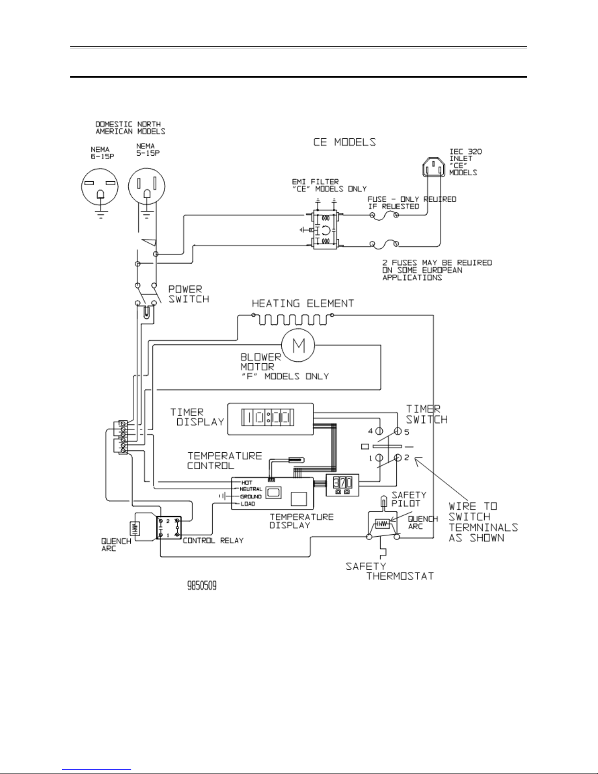
Wiring Diagram
Page 4-6 TestEquity FS Series Ovens

Chapter 5 - Warranty
TestEquity LLC Limited Warranty
TestEquity LLC (TestEquity) warrants Environmental Chambers (Equipment) manufactured by TestEquity and supplied under
this contract to be free from defects in materials and workmanship under normal use and proper maintenance.
TestEquity will repair or replace any defective part for a period of THREE YEARS from the date of invoice. TestEquity reserves
the right to require any defective part be returned, freight prepaid, to TestEquity’s factory or to inspect any defective part at the
Purchaser’s site. TestEquity shall have sole discretion to determine whether any part is defective and whether any defective part
will be repaired or replaced. This limited warranty shall extend to any standard chamber accessory and component part which is
normally sold by TestEquity. Non-standard accessories and component parts specified by the Purchaser shall be warranted only
to the extent of the original manufacturer's warranty, if any exists.
If the repair or replacement is performed in the FIRST YEAR from the date of invoice, TestEquity will also pay for the labor
associated with the repair at the Purchaser’s site, subject to TestEquity’s prior approval. During the SECOND and THIRD YEAR
of the warranty period, Purchaser will be responsible for the installation and cost of installation of replacement or repaired parts.
Purchaser shall notify TestEquity in writing of any alleged defect within 10 days after its discovery within the warranty period.
TestEquity reserves the right to satisfy the labor portion of this limited warranty either through its own service personnel or an
authorized agent. In order to provide expeditious service, TestEquity reserves the right to satisfy its limited warranty obligation
by sending replacement parts to be installed by the Purchaser if they can be installed easily without special tools or training.
TestEquity reserves the right to satisfy this limited warranty by requiring the Purchaser to return the Equipment to TestEquity
when such return is feasible.
TestEquity must initiate field service for in-warranty claims. Purchaser will not be reimbursed for labor if they initiate service on
their own without prior approval from TestEquity. Replacement parts must be supplied by TestEquity for in-warranty claims.
Purchaser will not be reimbursed for parts they buy on their own without prior approval from TestEquity.
The following parts are excluded from this limited warranty and are sold as-is or are considered expendable: paint and cosmetic
surface finishes and treatments, and port plugs.
This limited warranty shall extend in full to Equipment installed within continental United States and Canada. For all other
locations, Purchaser is responsible for all labor costs for repairs or parts installation, and for all shipping costs associated with
providing replacement parts.
This limited warranty does not cover: (1) Defects or damages arising as the result of shipment by common carriers or private
transportation, unless TestEquity undertakes shipment and transportation of the Equipment to Purchaser’s site or contractually
assumes the risk of damage to the Equipment in shipment; (2) Defects or damages arising out of, or as the result, of mishandling,
modification, or improper start up, installation or maintenance of the Equipment (including start up, installation or maintenance
not in accordance with TestEquity’s written procedures); (3) Defects or damages resulting from, or arising out of, abuse, misuse,
neglect, intentional damage, accident, fire, flood, earthquake, or any other act of God.
This warranty as to Equipment is LIMITED to repair or replacement of parts or Equipment in the determination of TestEquity
LLC THE FORGOING LIMITED WARRANTY IS IN LIEU OF ALL OTHER WARRANTIES INCLUDING THE IMPLIED
WARRANTIES OF FITNESS FOR A PARTICULAR PURPOSE AND MERCHANTABILITY. TestEquity LLC DISCLAIMS
ANY LIABILITY FOR ANY DAMAGES RESULTING FROM DELAY OR LOSS OF USE IN SERVICE OR REPAIR, OR
FOR INCIDENTAL OR CONSEQUENTIAL DAMAGES ARISING OUT OF OR IN CONNECTION WITH THE USE OR
PERFORMANCE OF THE EQUIPMENT, EXCEPT AS STATED IN THIS PARAGRAPH.
This limited warranty cannot be modified in any way except in writing by both TestEquity and Purchaser. Invalidation of any one
or more of the provisions of this limited warranty shall in no way affect any of the other provisions hereof, which remain in full
force and effect.
This limited warranty shall be extended only to the first Purchaser of this Equipment and is not transferable.
 Loading...