

Page 1
INSTRUCTION MANUAL
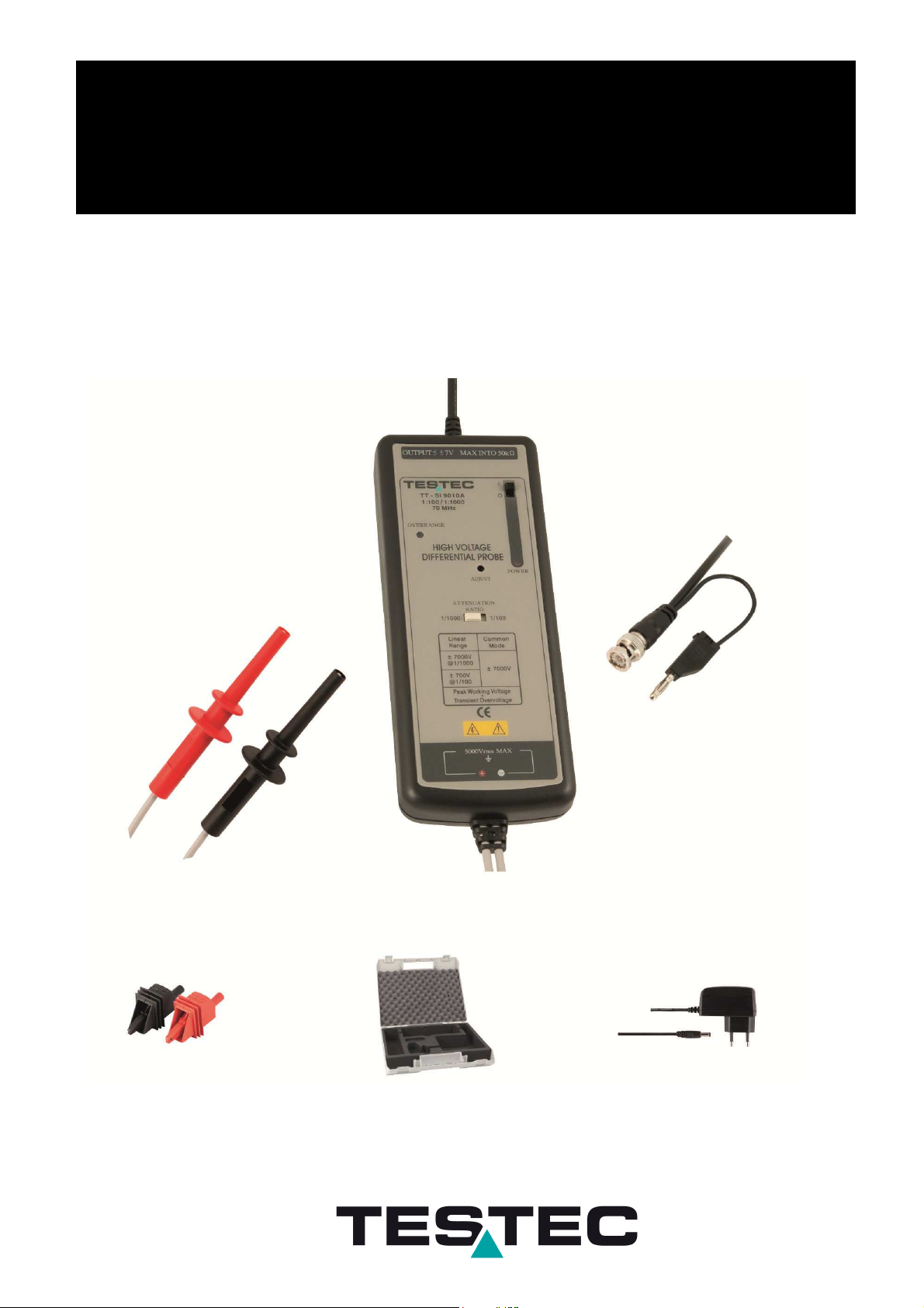
TT-SI 9010A
70MHz Active Differential Probe
Page 2
Safety Symbols
These probe is in compliance with IEC-61010-031 CAT I, Pollution Degree 2
1. Safety Terms and Symbols
Terms appear in this manual:
___________________________________________________
WARNING. Warning statements identify conditions or practice that
could result in injury or loss life.
___________________________________________________
CAUTION. Caution statements identify conditions or practice that
could result in damage to this product or other property.
Connect it to safety earth ground using the wire recommended in
the user’s manual.
High voltage danger
The symbol on an instrument indicates that the user should refer
to the operating instructions located in the manual.
2. General Safety Summary
Review the following safety precautions to avoid injury and prevent damage to this probe
or any products that connected to it.
Observe Maximum Working Voltage
To avoid any injury, do not use the probe under the condition that the voltage between
either input lead or earth is above 5000Vrms CAT I. This voltage rating applies to both
settings 1/100 & 1/1000.
Page 3

Must be Grounded
This probe is grounded with the shell of BNC connector and an auxiliary grounding terminal,
through the grounding conductor of the power cord of the measurement instrument. Before
making connections to the input leads of this probe, ensure that the output BNC connector
is attached to the BNC connector of the measurement instrument and the auxiliary
grounding terminal is connected to a proper ground, while the measurement instrument is
properly grounded.
Do Not Operate Without Covers
To avoid electric shock or fire hazard, do not operate this probe with covers removed.
Do Not Operate in Wet/Damp Conditions
To avoid electric shock, do not operate this probe in wet of damp conditions.
Do Not Operate in Explosive Atmosphere
To avoid injury or fire hazard, do not operate this probe in an explosive atmosphere.
Avoid Exposed Circuit
To avoid injury, remove jewelry such as rings, watches, and other metallic objects. Do not
touch exposed connections and components when power is present.
Use Proper Power Source
To ensure this probe function well, use four AA cells or 6VDC/60mA or regulated
9VDC/40mA mains adaptor or power lead. Do not operate this probe from a power source
that applies more than the voltage specified.
Do Not Operated With Suspected Failures
If you suspect there is damage to this probe, have it inspected by qualified service
personnel.
Cleaning
Use a soft cloth to clean the dirt. Prevent damage to probe. Avoid immersing the probe.
Avoid using abrasive cleaners. Avoid using chemicals contains benzene or similar solvents.
3. Description
By enabling conventional oscilloscopes to display and measure in-circuit waveforms that are
referenced to high common mode voltages. The differential probe extends the measurement
capability of oscilloscopes in electronic power converters, inverters, motor speed controls,
switch mode power supplies, and many applications.
Page 4
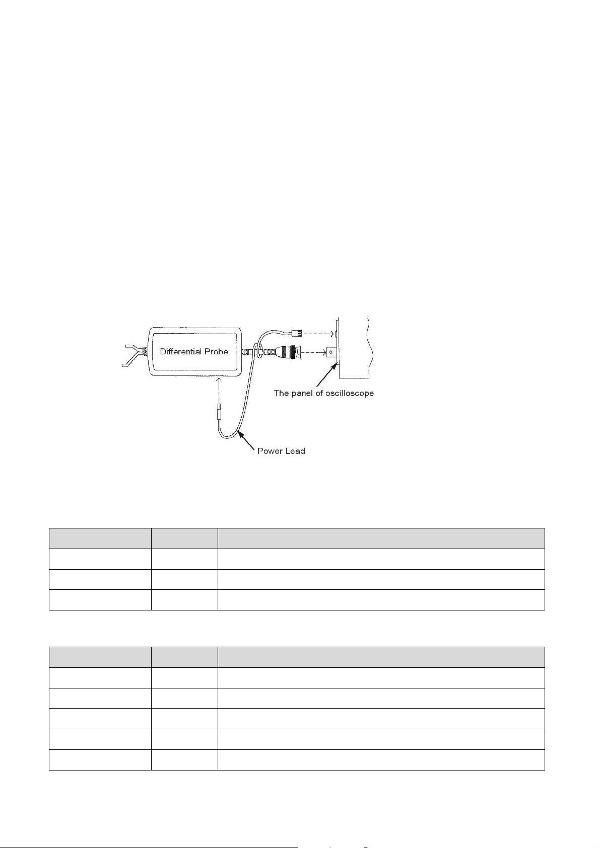
4. Installation
a. Simply plug-in the BNC output connector to the vertical input of a general purposed
oscilloscope or other measurement instrument, and connects the auxiliary grounding
terminal to a proper ground. The measurement instrument must have a ground referenced.
b. Connect an appropriate power source to this probe and or enter the batteries, then turn it
on.
c. Select the proper attenuation ratio. When measuring signals below 700V switch the
attenuation ration to 1/100 in order to get higher resolution and less noise ratio. Otherwise,
set the attenuation ratio to 1/1000.
WARNING. To protect against electric shock, use only the
accessories supplied with this probe.
d. Using the appropriate probe accessories, connect the inputs to the circuits under
measurement.
CAUTION. This probe is to carry out differential measurement
between two points on the circuit under measurement.
This probe is not for electrically insulating the circuit
under measurement and the measuring instrument.
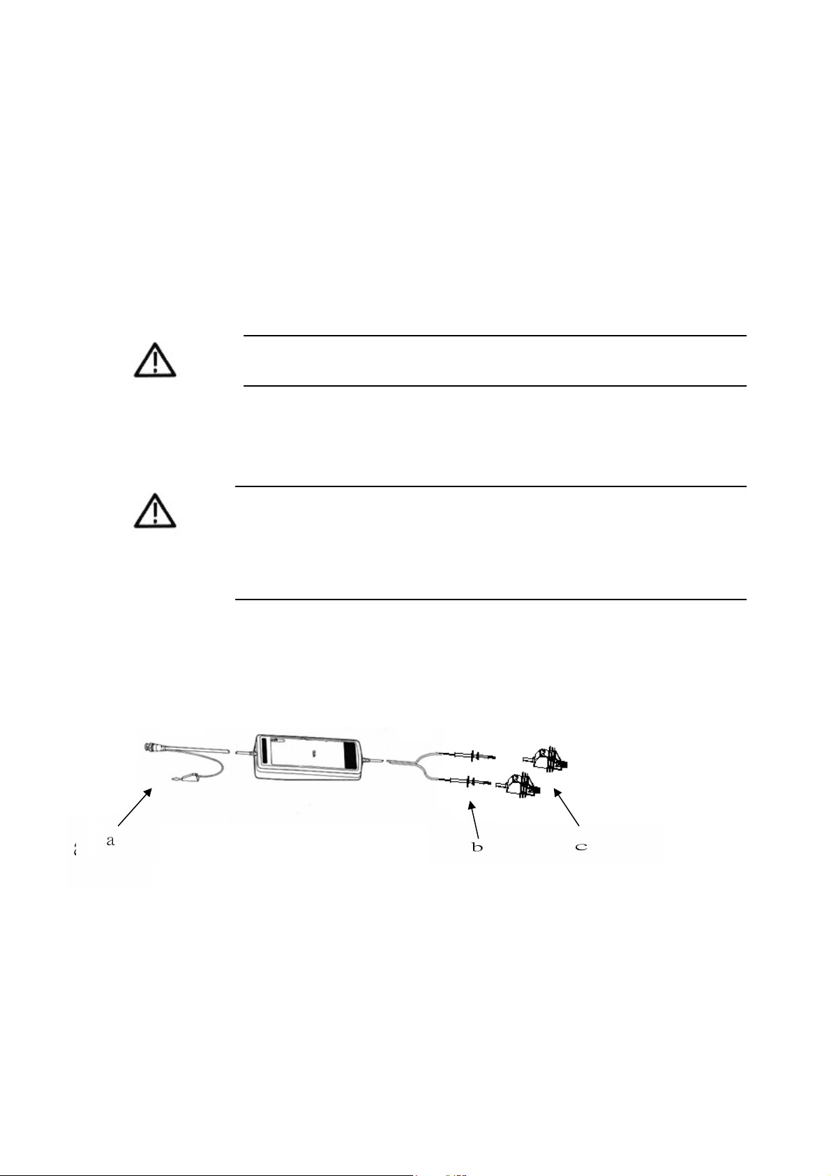
5. Appearance
The differential probe looks as follows.
a. Output Cable The BNC output connector and an auxiliary grounding terminal
are connected to the oscilloscope.
b. Input Leads The input leads of the differential probe connect to the
HV alligator clips that come with the probe.
c. HV Alligator Clips For safe test point connection
Page 5
6. Offset Adjustment
If the offset voltage is too large, short the input leads and turn the adjust variable resistor
(DC voltage adjustment) which you find in the hole of the panel by using a flat-head
screwdriver until the offset voltage is lowest.
7. Available Power Sources
a. 4 x AA batteries
b. Mains adaptor (6VDC/60mA or regulated 9VDC/40mA),
c. Lemo® Power Cord, for oscilloscopes with power output - Lemo® connector.
d. Probus® Power Cord, for oscilloscopes with power output - Probus
connector.
e. USB Power Cord, for oscilloscopes which offer USB connector.
®
8. Accessories supplied
Type Order-No. Description
TT-SI G3 15105
TT-SI NT 15100 Mains Adapter
TT-SI HC 15160
9. Optional Accessories
Type Order-No. Description
HV Alligator Clips red and black
Hardcase
TT-SI PROBUS 15150
TT-SI LEMO 15151
TT-SI USB 15152
TT-SI EPL1 15140
TT-SI EPL2 15141
Power Lead with PROBUS-Connector
Power Lead with LEMO-Connector
Power Lead with USB-Connector
1 to 3 Power Splitter
1 to 4 Power Splitter
Lemo® and Probus® are the registered trademarks
Page 6

Ambient Storage Temperature
Ambient Operating Humidity
Ambient Storage Humidity
Length of BNC Cable
Length of Input Leads
10. Specifications
TT-SI 9010A
Bandwidth DC to 70MHz (-3dB)
Attenuation Ratio 1:100 / 1:1000
DC-Accuracy ±2%
Rise Time 5ns
Input Impedance
Input Voltage
- Differential Range
Input Voltage
- Common Mode Range
Input Voltage
- Absolute Max.
(Differential or Common Mode)
Measurement Category CAT I
Output Voltage
- Swing
Output Voltage
- Offset (typical)
Output Voltage
- Noise (typical)
50MΩ // 10pF each side to ground
1:100 ±700V (DC+peak AC) or 500Vrms
1:1000 ±7000V (DC+peak AC)
or 5000Vrms
1:100 and 1:1000
±7000V (DC+peak AC) or 5000Vrms
1:100 and 1:1000
±7000V (DC+peak AC)
or 5000Vrms
±7V (into 50kΩ load)
<±5mV
0,9mVrms
Source Impedance (typical) 50Ω (for using 1MΩ input system oscilloscope)
CMRR (typical) -80dB @50Hz, -60dB @20kHz
Ambient Operating
Temperature
Power Requirements
- Standard
Power Requirements
- Optional
Weight 500g
Dimensions (LxWxH) 202mm x 83mm x 38mm
-10°C to 40°C
-30°C to 70°C
25% to 85% RH
25% to 85% RH
4 x AA Cells
Power lead or Mains Adapter
(6VDC/60mA or regulated 9VDC/40mA)
90cm
60cm
a. The supplied voltage must be less than 12V and greater than 4.4V, otherwise the probe
could be damaged or can’t be operated properly.
b. Polarity is “+” inside and “–” outside. For wrong polarity, built-in circuit protects the
probe, no danger or damage will occur.
c. When the voltage of the cells become too low, the power indicator on the will flicker.
Page 7
11. Differential’, Common Mode’ and ‘Absolut max.’ Voltage
Range limit is the lesser of the ‘DC+Peak AC’ and RMS values.
Input voltage at positive input lead = V(+) / Input voltage at negative input lead = V(-)
- Differential Range= V(+) –V(-)
- Common Mode Range= [V(+) +V(-) ] /2
The input-specification of differential range and common mode range has to be meet
at the same time so that output specification could be meet. Absolute Max. Voltage is
defined for when the input condition do not meet specification of differential range and
common mode range. Under this condition, the output of probe could not be guaranteed
within specification. When larger then this condition, the probe maybe broken.
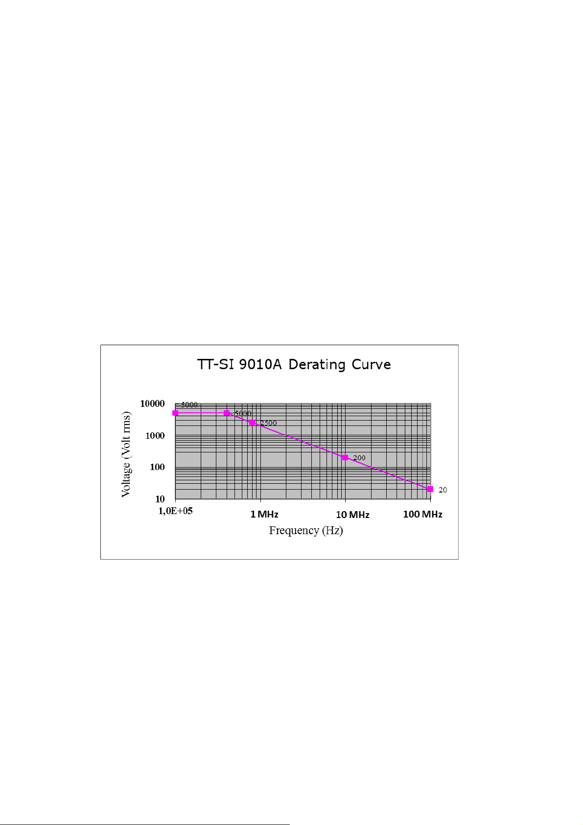
12. Derating Curve
The derating curve of the absolute maximum input voltage in common mode is shown as
follows.
13. Inspection Procedure
a. Connect the BNC output connector to the vertical input of a general purposed
oscilloscope.
b. Install four AA cells or connect an appropriate mains adaptor or power lead to the correct
line voltage.
c. Set the oscilloscope input coupling to DC and the 1V/div. Center the trace on the display.
d. Connect the inputs of the probe to power lines.
e. Set the range of the probe to 1/100.
f. Then, a 50Hz/60Hz sine-wave of proper amplitude will be displayed on the screen of the
oscilloscope and this means the probe is working properly.
Page 8

Testec Elektronik GmbH
Fritz-Klatte-Str. 6
D - 65933 Frankfurt
Telefon: +49 (0) 69 - 94 333 5 - 0
Fax: +49 (0) 69 - 94 333 5 – 55
E-Mail:
http://www.testec.de
info@testec.de
 Loading...