

Page 1
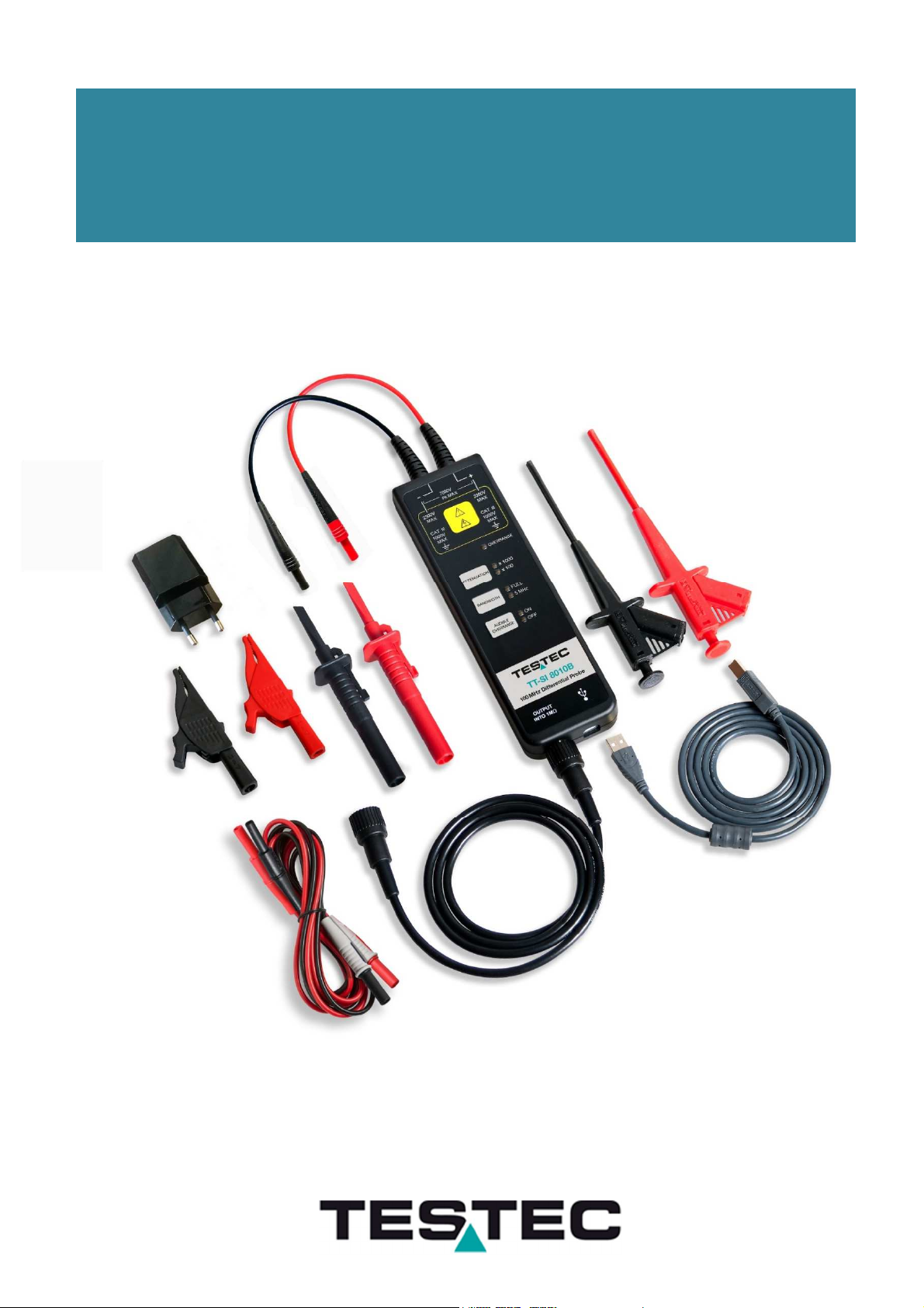
ACTIVE DIFFERENTIAL PROBES
INSTRUCTION MANUAL
TT-SI 8000 SERIES
Page 2

Page 3

Safety Summary
To avoid personal injury and/or product damage, review and comply
with the following safety precautions. These precautions apply to both operating and
maintenance personnel and must be followed during all phases of operation, service,
and repair of this probe.
A
WARNING
statement calls attention to an operating procedure, practice,
or condition, which, if not followed correctly, could result in injury or death to
personnel.
A
CAUTION
condition, which, if not followed correctly, could result in damage to or destruction
of parts or the entire product.
Do Not Work Alone
Do not work alone when working with high voltages.
Inspect the Probe
statement calls attention to an operating procedure, practice, or
Inspect the probe and accessories for cracks and frayed or broken leads before each
use. If defects or damages are noted, DO NOT USE the probe.
Dry Conditions
Hands, shoes, floor, and work bench must be dry. Avoid making
measurements under humidity, dampness, or other environmental conditions
that might affect safety.
Do Not Remove the Probe’s Casing
Removal of the probe’s casing may expose you to electric shock. If necessary,
disconnect the inputs and outputs of the probe before opening the case.
Hazardous Contact
To avoid injury, remove jewelry such as rings, watches, and other metallic objects. Do
not touch exposed connections and components when power is present.
Unexpected Charges
Hazardous voltages may be present in unexpected locations in circuitry being
tested when a fault condition in the circuit exists.
Capacitors inside the instrument may retain a charge even if the instrument is
disconnected from its source of supply.
Use Only in Office-Type Indoor Setting
The probe is designed to be used in office-type indoor environments.
Do not operate the probe:
•
In the presence of noxious, corrosive, flammable fumes, gases, vapors,
chemicals, or finely-divided particulates.
•
In environments where there is a danger of any liquid
•
In air temperatures exceeding the specified operating temperatures.
•
In atmospheric pressures outside the specified altitude limits or where the
surrounding gas is not air.
spilled
on the probe.
Man_8000_0120 www.testec.de 1
Page 4
Not for Critical Applications
This probe is not authorized for use in contact with the human body or for use as a
component in a life-support device or system.
Do Not Substitute Parts
Do not install substitute parts or perform any unauthorized modification to the
instrument.
Only Qualified Personnel
Only qualified personnel should use this probe. This differential voltage probe is
designed to be used by personnel who are trained, experienced, or otherwise
qualified to recognize hazardous situations and who are trained in the safety
precautions necessary to avoid possible injury when using such a device.
Observe Maximum Working Voltage
Do not use any probe above its maximum working voltage ranges. See
specifications on page 7.
Use Proper Power Source
Do not operate this probe from a power source that applies more than the voltage
specified.
Must be Grounded
This probe is grounded by the shell of the BNC connector through the grounding
conductor of the power cord of the measurement instrument. Before making
connections to the input leads of this probe, ensure that the output BNC connector is
attached to the BNC connector of the measurement instrument, and that the
measurement instrument is properly grounded. Whenever it is likely that the ground
protection is impaired, you must make the instrument inoperative and secure it
against any unintended operation.
Terms and Symbols
The following symbols appear on the product or in its documentation:
Direct voltage
Both direct and alternating voltage
Caution, possibility of electric shock
Caution, see documentation for details
Earth Ground
Man_8000_0120 www.testec.de 2
Page 5
Definitions
Measurement Category II (CAT II)
refers to local-level electrical distribution, such as that provided by a standard wall
outlet or plug-connected equipment. Examples of CAT II measurements would be
household appliances, portable tools, and similar modules.
Measurement Category III (CAT III)
refers to measurements on hard-wired equipment in fixed installations, distribution
boards, and circuit breakers that form part of a building wiring installation. Other
examples are wiring, including cables, bus bars, junction boxes, switches, socket
outlets in the fixed installation, and stationary motors with permanent connections to
fixed installations
Pollution Degree 2
refers to an operation environment where normally only dry, non-conductive pollution
occurs. Temporary conductivity caused by condensation can be expected.
Working CAT rating is equal to that of the lowest rated element
within the test set-up.
Compliance Statements
EC Declaration of Conformity
The product conforms to the applicable European Union requirements per
IEC 61010-031:2015 Safety requirements
for electrical equipment for measurement, control and laboratory use.
Part 31: Safety requirements for hand-held probe assemblies for electrical
measurement and test.
EU RoHS Compliance
The probe and accessories conform to the 2011/65/EU RoHS2 Directive.
Disposal of Old Electrical & Electronic Equipment
(Applicable in the European Union and other European countries with
separate collection systems). This product is subject to Directive
2012/19/EU of the European Parliament and the Council of the European
Union on waste electrical and electronic equipment (WEEE), and in
jurisdictions adopting that Directive, is marked as being put on the market
after August 13, 2005, and should not be disposed of as unsorted
municipal waste. Please utilize your local WEEE collection facilities in the
disposition of this product and
otherwise observe all applicable requirements.
This probe is in compliance with IEC 61010-031:2015 CAT III, Pollution Degree 2.
Man_8000_0120 www.testec.de 3
Page 6

1 Introduction
Overview
The TT-SI 8000 differential probe series allows safe, accurate measurement between
two voltage points where neither point is referenced to ground. The probes are
designed for high sensitivity measurements up to 200 MHz bandwidth and up to
7000V differential voltage. The probes are compatible with oscilloscopes from all
major manufacturers.
Features
•
•
•
•
•
•
•
•
Initial Inspection
Meets IEC 61010-1:2015 safety standard
Selectable attenuation settings
Offset setting function
5 MHz bandwidth limit function to remove noise and interferences.
Overrange sound & light alarm
High accuracy (±2%)
Powered through USB or USB to mains adapter
Over range indicator LED
This unit is tested prior to shipment. It is therefore ready for immediate use upon
receipt. An initial physical inspection should be made to ensure that no damage has
been sustained during shipment. After the inspection, verify the contents of the
shipment.
Delivery Content
•
•
•
•
•
•
• 1 x insulated BNC cable, 100 cm – TT-SI BN8
• 1 x USB power cable, 150cm – TT-SI USB8
• 1 x USB power adapter 5V/1A – EU version – TT-SI NT8
• 1 x User manual
1 x differential probe - TT-SI 8000 series
2 x pincer clips, black & red – TT-SI GR82
2 x hook clips, black & red – TT-SI GR81
2 x alligator clips, black & red – TT-SI CR81
2 x alligator clips, black & red – TT-SI CR82 (TT-SI 8010A & B instead of CR81)
2 x 4mm test leads, black & red – TT-SI TL8
Man_8000_0120 www.testec.de 4
Page 7

Max.
Input
Voltage
Model Overview
Model
TT-SI 8071 700V 70MHz x10/x100
TT-SI 8050 1500V 70MHz x50/x500
TT-SI 8051 1500V 100MHz x50/x500
TT-SI 8052 1500V 200MHz x50/x500
TT-SI 8110 2800V 100MHz x100/x1000
TT-SI 8010A 7000V 70MHz x100/x1000
TT-SI 8010B 7000V 100MHz x100/x1000
Differential
Bandwidth Attenuation
2 Using the Probe
WARNING
At the time of powering on the probe, the input leads must not be connected
to an item to be tested. Never operate the probe with the case open.
CAUTION
This probe is used to carry out differential measurements between two
points on the circuit under test. This probe is not designed for electrically
insulating the circuit under test or the measuring instrument.
Getting Started
1. Connect the BNC output connector to the vertical input of a general purposed
oscilloscope. The oscilloscope must have a ground referenced.
2. Connect power through USB or USB-adapter.
3. LED’s will turn on.
4. The default factory setting is high attenuation ratio, FULL bandwidth and audible
alarm is on. The probe has an automatic memory function, so it saves the state
before power off.
Test Procedure
1. Connect the BNC output connector to the vertical input of the oscilloscope.
2. Set the attenuation setting on the oscilloscope to match the probe setting.
3. Connect the input of probe to a function generator. Then select a square-wave
output of 10 V amplitude and 100 kHz frequency.
4. The square-wave will be displayed on the screen of the oscilloscope. The
oscilloscope should show the same voltage and frequency as the function
generator. This indicates the probe is working properly.
Man_8000_0120 www.testec.de 5
Page 8

3 Product Overview
Probe Inputs
Maximum Differential Voltage
Common Mode Voltage and
Maximum Input Voltage to Earth
Overrange Indicator
Attenuation Selection Button and Indicators
Bandwidth Limit Button and Indicators
Audible Overrange On/Off Button and Indicators
Load Requirement
USB Power Lead Input
BNC Output
Man_8000_0120 www.testec.de 6
Page 9

4 Specifications
TT-SI 8071 TT-SI 8110
Bandwidth (-3dB)
70MHz
TT-SI 8050 70MHz
TT-SI 8051 100MHz
TT-SI 8052 200MHz
TT-SI 8010A 70MHz
100MHz
TT-SI 8010B 100MHz
TT-SI 8050 ≤5ns
Rise Time ≤5ns
DC-Accuracy ±2% ±2% ±2% ±2%
Attenuation Ratio x10/x100 x50/x500 x100/x1000 x100/x1000
Maximum Input Voltage
Differential Mode
(DC+Peak AC)
Maximum Input Voltage
Common Mode
(DC+Peak AC)
Maximum Input Voltage
each Side to Ground (Vrms)
Single-
Input
Impedance
Input
Capacitance
CMRR
Input referred Noise
Ended to
Ground
Between
Inputs
SingleEnded to
Ground
Between
Inputs
DC
100kHz
1MHz
x10 ±70V x50 ±150V x100 ±280V x100 ±700V
x100 ±700V x500 ±1500V x1000 ±2800V x1000 ±7000V
±700V ±1500V ±2800V ±7000V
450V CAT II
600V
2.5MΩ 5MΩ 5MΩ 20MΩ
5MΩ 10MΩ 10MΩ 40MΩ
<4pF <4pF <4pF <5pF
<2pF <2pF <2pF <2.5pF
>80dB >80dB >80dB >80dB
>60dB >60dB >60dB >60dB
>50dB >50dB >50dB >50dB
70V
700V
<20mV
<120mV
TT-SI-8051 ≤3,5ns
TT-SI 8052 ≤1,75ns
600V CAT III
1000V CAT II
150V
1500V
<50mV
<300mV
≤3.5ns
600V CAT III
1000V CAT II
280V
2800V
<100mV
<600mV
TT-SI 8010A ≤5ns
TT-SI 8010B ≤3,5ns
1000V CAT III
2300V
700V
7000V
<200mV
<1.2V
Differential Overvoltage
Detection Level
Propagation
Delay
Bandwidth Limit Filters ≥-3dB@5MHz
Weight 230g
Input Lead Length 28cm (17cm for TT—SI 8052)
Automatic Save Yes
Offset Setting Function
Termination Load ≥100kΩ
Power Supply USB 5V/1A and 220V Adapter
Safety standard EN61010-031: 2015
Probe approx. 9ns
BNC Cable approx. 5ns
x10 ≥70V x50 ≥150V x100 ≥280V x100 ≥700V
x100 ≥700V x500 ≥1500V x1000 ≥2800V x1000 ≥7000V
Yes( when set in test mode)
Specifications are subject to change without notice. All specifications apply to the unit after a temperature
stabilization time of 20 minutes over an ambient range of 25°C ± 5°C.
Man_8000_0120 www.testec.de 7
Page 10

5 Voltage Derating Curve
Derating Curve TT-SI 8071
SI 7005 Voltage Derating
Derating Curve TT-SI 8050, 8051, 8052
TT-
Man_8000_0120 www.testec.de 8
Page 11

Derating Curve TT-SI 8110
Derating Curve TT-SI 8010A, 8010B
Man_8000_0120 www.testec.de 9
Page 12

6 Accessories Description
TT-SI CR81 - Alligator Clips TT-SI CR82 - Alligator Clips
one pair black and red one pair black and red
1000V CAT III / 600V CAT IV 1000V CAT III / 600V CAT IV
TT-SI GR82 - Pincer Clips TT-SI GR81 - Hook Clips
one pair black and red one pair black and red
1000V CAT III 1000V CAT III
TT-SI TL8 - Extension Test Leads Leads 4mm,
1000V CAT III, 100cm
one pair black and red
TT-SI BN8 - BNC Output Lead, 100cm
TT-SI USB8 - USB Power Lead, 150cm
TT-SI NT8 – USB Mains Adapter 5V/1A
Man_8000_0120 www.testec.de 10
Page 13

7 Cleaning
This probe does not require any particular cleaning. If necessary, clean the case
with a soft cloth.
WARNING
Dry the probe thoroughly before attempting to make voltage
measurements.
CAUTION
Avoid immersing or using abrasive cleaners or solvents containing
Benzene (or similar solvents) on the probe as these can cause
deterioration of the probe body and cables.
Man_8000_0120 www.testec.de 11
Page 14

8 Service & Warranty Information
Limited One-Year Warranty
Testec Elektronik GmbH warrants these products to be free from defective material
or workmanship for a period of 1 year from the date of original purchase. Under
this warranty, Testec Elektronik GmbH is limited to repairing the defective device
when returned to the factory, shipping charges prepaid, within the warranty
period.
Units returned to Testec Elektronik GmbH that have been subject to abuse,
misuse, damage, or accident, or have been connected, installed, or adjusted
contrary to the instructions furnished by Testec Elektronik GmbH, or that have
been repaired by unauthorized persons, will not be covered by this warranty.
Testec Elektronik GmbH reserves the right to discontinue models, change
specifications, price, or design of this device at any time without notice and without
incurring any obligation whatsoever.
The purchaser agrees to assume all liabilities for any damages and/or bodily injury
which may result from the use or misuse of this device by the purchaser, his
employees, or agents.
This warranty is in lieu of all other representations or warranties expressed or
implied and no agent or representative of Testec Elektronik GmbH is authorized to
assume any other obligation in connection with the sale and purchase of this
device.
Service
If you have a need for repair services, technical, or sales support, please contact
us:
Testec Elektronik GmbH
Fritz-Klatte-Str. 6
65933 Frankfurt / Germany
Tel.: +49 (0) 69 – 9433350
E-Mail: service@testec.de
www.testec.de
Man_8000_0120 www.testec.de 12
Page 15

Man_700_0919 www.testec.de 1
Page 16

TT-SI 8XXX Differential Probe User’s Manual
© 2020 TESTEC Elektronik GmbH. All rights reserved.
Unauthorized duplication of TESTEC documentation materials is strictly prohibited.
Customers are permitted to duplicate and distribute
TESTEC documentations for internal educational purposes
Man_700_0919 www.testec.de 2
 Loading...