

Page 1
For further information www.tessilmare.com
Visit our video channel www.youtube.com/tessilmare
TOOLS
BINO40 PROFILES - ASSEMBLY INSTRUCTIONS
A4 (316) type self drilling screws
Oval head style (TGS)
Phillips Screw Size N.10, Head 9,5 mm Shank 4,8 mm
Specic codes: DIN7983 or UNI6956, also ISO 7051
WARNING: it is better not to use A2 screws
Drill and Screwdriver
PROJECTED AND DESIGNED BY TESSILMARE IN ITALY
PATENT PENDING
Tip 4/4,2 mm
Rubber hammer
Page 2
1. PREPARATION OF THE PROFILE
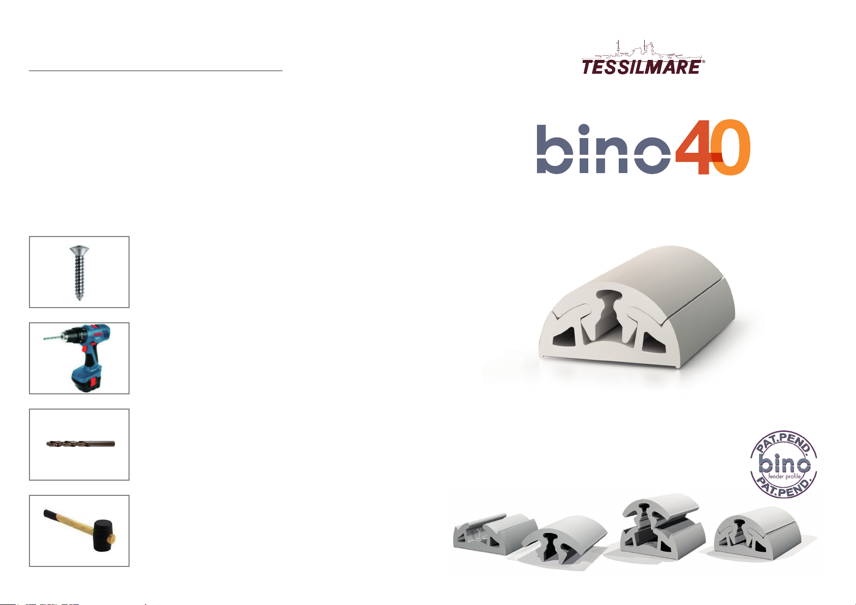
The Bino 40 prole consists of 2 modules,
one base and one “top” which covers the
xing screws.
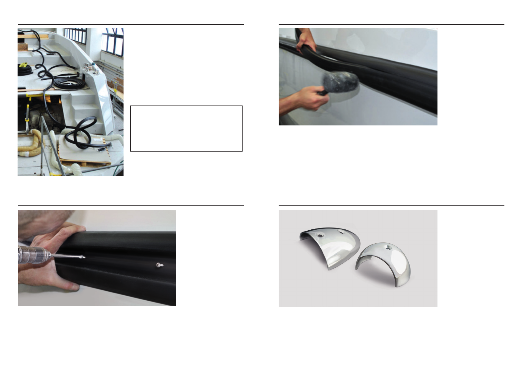
The product ts cold as its exibility is very
high.
Lay the prole on the ground around the
boat or on the boat itself, the more the prole
is properly outstretched, the easier it is to
install it.
The peculiarity of this product is that
it can be adapted to very complex
curves, with both negative and
positive acute radius, the product
does not need any pre-heating so the
assembly is fast.
The modularity of Bino 40 allows you to
replace one of the two parts over time,
indistinctly.
3. APPLICATION OF THE TOP PROFILE
Install the top prole by pressing it with a rubber hammer.
2. FIXING THE BASE PROFILE THROUGH SCREWS AND RIVETS
Drill and screw the base prole directly to the boat.
4. FINISH WITH THE END-CAPS
 Loading...