

Page 1
o
o
a
a
o
o
n
n
A
A
F
F
S
S
3
3
0
0
3
3
IInnssttaallllaattiioonn,,
H
H
ppeerraattiioonn aanndd mmaaiinntte
n
n
d
d
b
b
o
o
o
o
e
k
k
aannccee
PPuulllleerr--TTeennssi
i
nneerr M
Mooddeell::
Page 2

ATTENZIONE
Per motivi di sicurezza durante il trasporto la macchina è fornita senza olio idraulico e senza
carburante. Nel presente fascicolo troverete informazioni sulle caratteristiche e le quantità
richieste. In caso di dubbio consultare la TESMEC.
WARNING
The machine is supplied without hydraulic oil and fuel during transport for precautionary
measures. Please refer to this manual for all information regarding the characteristics and
quantities required. Should you have any doubt, please get in touch with TESMEC.
ATTENTION
Pour mesures de sécurité, pendant le transport la machine est livrée sans huile hydraulique
et sans carburant.
Référez-vous à ce manuel pour renseignements nécessaires sur les caractéristiques et
quantités. En cas de doute veuillez contacter TESMEC.
ATENCION
Por motivos de seguridad la máquina se transporta sin aceite hidráulico y sin combustible.
En el presente fascículo encontrarán informaciones acerca de las características y de las
cantidades requeridas. En caso de dudas, consultar a TESMEC.
ATENÇÃO
Por razões de segurança durante o transporte, a máquina é fornecida sem óleo hidráulico e
combustível. No presente folheto poderão encontrar as informações sobre as características
a as quantidades requeridas.
Caso tenham alguma dúvida, rogamos-lhes pôr-se em contacto com a TESMEC.
ACHTUNG
Aus Sicherheitsgründen während des Transportes, wird die Maschine ohne Öl und Kraftstoff
geliefert. Im vorliegenden Gebrauchsanweisungsheft werden Sie Informationen über die
Eigenschaften und Mengen des Öls finden.
Wenn Sie im Zweifel sind, fragen Sie TESMEC um Rat.
ПРЕДУПРЕЖДЕНИЕ
Из соображений безопасности, при поставке машина транспортируется без рабочей
жидкости в гидравлической системе и топлива.
Пожалуйста, пользуйтесь настоящим руководством для получения любых сведений,
касающихся характеристик и заправочных емкостей.
В случае каких-либо сомнений, пожалуйста, свяжитесь с компанией ТЕСМЕК.
- 24050 Grassobbio (Bg) via Zanica, 17/O - 24060 Endine Gaiano (Bg) via Pertegalli
Tel. 0039 / 035 / 4232911 Tel. 0039 / 035 / 825024
Telefax 0039 / 035 / 4522445 Telefax 0039 / 035 / 826375
E-mail: [email protected] E-mail: [email protected]
Page 3

PULLER
-
TENSIONER
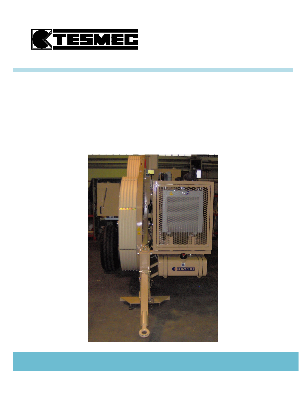
Model: AFS303
PULLER-TENSIONER
Model: AFS303
Serial number
………………
Manufacturing year
………………
Working order
………………
USE AND MAINTENANCE INSTRUCTIONS
Page 4

PULLER-TENSIONER
Model: AFS303
Manual: MI-AFS303-320-00-GB
Date: 30.03.2015
Author: MC
Page: 1 of 32
1. GENERAL INDEX
Page
1. GENERAL INDEX 1
2. GENERAL DATA AND PRESCRIPTIONS 3
2.1 MANUFACTURER 3
2.2 COMMUNICATIONS WITH THE MANUFACTURER 3
2.3 TYPOLOGY AND USING FIELD 3
2.4 PERFORMANCES 3
2.5 TECHNICAL CHARACTERISTICS 4
2.6 ACOUSTIC EMISSION 4
2.7 GENERAL INFORMATION FOR THE MACHINE USE 4
2.8 GENERAL PRESCRIPTIONS FOR THE OPERATOR CHARGED OF THE MACHINE USE 4
2.9 GENERAL PRESCRIPTIONS FOR THE OPERATOR CHARGED OF THE MACHINE
MAINTENANCE 5
2.10 KNOWLEDGE AND CARE OF THE INSTRUCTION MANUAL 5
2.11 CONDITION OF USE 5
2.12 TEMPERATURE LIMITS FOR HYDRAULIC OIL 6
2.13 USE NOT ALLOWED 6
2.14 RESPONSIBILITY 7
2.15 APPLIED NORMS 7
3. TRANSPORT AND POSITIONING INSTRUCTIONS 8
3.1 MACHINE LIFTING 8
3.2 TRANSPORT TYPOLOGIES AND PACKAGE 8
3.3 UNPACKING 8
3.4 ASSEMBLING OPERATIONS 9
3.5 TRANSPORT ON TRAILER 9
3.6 POSITIONING AND ANCHORING 9
4. INSTRUCTION FOR USE 11
4.1 PRESCRIPTIONS FOR THE OPERATOR 11
4.2 CONTROLS 11
4.3 PRELIMINARY OPERATIONS 11
4.4 MACHINE SET-UP 12
4.5 ELECTRONIC MULTIFUNCTION DAVICE PAGES 13
4.6 STARTING OF THE MACHINE 14
4.7 PULL CONTROL 14
4.7.1 PULL LIMITING DEVICE SETTING 14
4.7.2 PULL PROGRAMMING DEVICE SETTING 15
4.8 CONNECTION MACHINE-HYDRAULIC HEAD OF THE REEL ELEVATOR OR REEL WINDER 16
4.9 PULLING OPERATIONS 16
4.10 RELEASING THE ROPE 17
4.11 COMPRESSOR CONNECTION (OPTIONAL) 17
4.12 PREHEATING KIT (OPTIONAL) 18
4.13 PREHEATING CONTROL PANEL PROGRAMMING (OPTIONAL) 18
4.13.1 GENERAL (OPTIONAL) 18
4.13.2 OPERATION (OPTIONAL) 18
4.13.3 SWITCHING THE HEATER ON (OPTIONAL) 19
4.13.4 SWITCHING THE HEATER OFF (OPTIONAL) 19
4.13.5 SETTING TIME/DAY OF THE WEEK (OPTIONAL) 19
4.13.6 VIEWING THE TIME (OPTIONAL) 19
4.13.7 PROGRAMMING HEATER STARTING TIME (OPTIONAL) 19
4.13.8 RECALLING/ERASING PRE-SET TIMES (OPTIONAL) 19
4.13.9 PROGRAMMING DURATION OF OPERATING TIME (OPTIONAL) 19
4.13.10 SETTING THE REMAINING OPERATING TIME (OPTIONAL) 19
4.13.11 SETTING THE WAKEUP TIME (OPTIONAL) 19
4.13.12 RECALLING/ERASING THE WAKEUP TIME (OPTIONAL) 20
4.14 ROPE LOCKING CLAMP (OPTIONAL) 20
4.15 POINTS TO REMEMBER 20
Page 5

PULLER-TENSIONER
Model: AFS303
Manual: MI-AFS303-320-00-GB
Date: 30.03.2015
Author: MC
Page: 2 of 32
4.16 END OF THE OPERATIONS 20
5. INSTRUCTION FOR USE – CONNECTED MACHINES 21
5.1 GENERAL ASPECTS 21
5.2 MACHINES SET-UP 22
5.3 CONNECTED MACHINES OPERATIONS 23
5.4 PULL CONTROL SETTING 23
5.4.1 PULL LIMITING DEVICE SETTING 23
5.4.2 PULL PROGRAMMING DEVICE SETTING 23
5.5 USING OF ELECTRONIC SPEED SYNCHRONIZER DEVICE (OPTIONAL) 24
5.6 ROPE LOCKING CLAMP (OPTIONAL) 24
5.7 ALARM CONDITION WHEN USING CONNECTED MACHINES 24
5.7.1 STRINGING LENGTH ERROR 24
5.7.2 SWITCH ON THE MACHINE WITH CONTROL NOT IN NEUTRAL 24
5.7.3 EMERGENCY STOP 25
5.7.4 CAN-BUS DIS-CONNECTION BETWEEN THE MACHINES 25
5.7.5 ROPE-CLAMP POSITION 25
5.7.6 GEAR-BOX LOW-PULL POSITION 25
5.7.7 CONNECTION MACHINE SELECTOR 25
5.7.8 COMPONENT FAULT 25
6. SAFETY CONDITIONS 26
6.1 SAFETY DEVICES 26
6.2 EMERGENCY STOP DEVICE 26
6.3 PERIODIC OPERATIONS 26
6.4 RESIDUAL RISKS 27
7. MAINTENANCE 28
7.1 GENERAL PRESCRIPTIONS 28
7.2 LEVELS CONTROL 28
7.3 TYRES INFLATION PRESSURE 28
7.4 SUGGESTED LUBRICANTS 28
7.5 ENDOTHERMIC ENGINE MAINTENANCE 28
7.6 HYDRAULIC CIRCUIT MAINTENANCE 29
7.7 REDUCTION GEAR MAINTENANCE 29
7.8 RADIATOR’S MAINTENANCE 30
7.9 GREASING 30
7.10 OTHER PERIODIC OPERATIONS 30
7.11 SUMMARY TABLE FOR ORDINARY MAINTENANCE 30
8. HOW TO DISABLE THE MACHINE 31
8.1 TRANSPORT 31
8.2 EXTENDED SERVICE STOP 31
8.3 STRIPPING 31
9. ENCLOSED DOCUMENTS 32
9.1 TABLES 32
9.2 SYSTEMS 32
9.3 OTHER DOCUMENTS 32
Page 6

PULLER-TENSIONER
Model: AFS303
Manual: MI-AFS303-320-00-GB
Date: 30.03.2015
Author: MC
Page: 3 of 32
TESMEC S.p.A.
Via Zanica, 17/O
24050 - GRASSOBBIO
BG - ITALY
tel. (+39)-035-4232911
fax (+39)-035-4522445
e-mail: [email protected]
Via Pertegalli, 2
24060 - ENDINE GAIANO
BG - ITALY
tel. (+39)-035-825024
fax (+39)-035-826375
e-mail: [email protected]
ATTENTION: the use with rope or conductor with diameter smaller than the max.
admitted one, will reduce the max. applicable pull in accordance with the min. granted
working load of the rope or of the conductor.
2. GENERAL DATA AND PRESCRIPTIONS
2.1 MANUFACTURER
2.2 COMMUNICATIONS WITH THE MANUFACTURER
For any information related to the machine (use, maintenance, spare parts) always state Model, Serial
Number, Manufacturing Year and Order. These data can be found in the machine-identifying table.
2.3 TYPOLOGY AND USING FIELD
Puller-tensioner mod. AFS303 is suitable for stringing one bundled conductor with max. diameter of 36
mm and for recovering one rope with 10 mm in diameter with a connector with max. diameter of 28
mm.
The machine is controlled by a hydraulic system that allows the machine to automatically work in
PULLER or in TENSIONER mode.
The power transmission to the large groove bull-wheels is transmitted through a closed hydraulic
circuit with a variable delivery pump and fixed displacement motor, with the possibility to change
continuously the speed in both rotating directions.
A hydraulic vacuum brake stops automatically the two bull-wheels should the work be interrupted and
a damage in the hydraulic circuit occur.
The machine is equipped with rapid couplers for connection to all types of reel winders and reel
elevators made by Tesmec; the frame is complete with a rigid axle for towing at max. 30 km/h.
2.4 PERFORMANCES
PULLER PERFORMANCES
Max. pull 25 kN
Speed at max. pull 2,5 km/h
Max. speed 4,5 km/h
TENSIONER PERFORMANCES
Max. tension 25 kN
Max. speed 5 km/h
Performances are referred to the machine without optional, at sea level and at 20°C.
Page 7

PULLER-TENSIONER
Model: AFS303
Manual: MI-AFS303-320-00-GB
Date: 30.03.2015
Author: MC
Page: 4 of 32
2.5 TECHNICAL CHARACTERISTICS
Bull-wheels diameter: 1500 mm with interchangeable nylon sectors
Diesel engine: 37,5 kW – 3000 rpm – KOHLER KDW 2204
Electric system: 12 V
Transmission: closed hydraulic circuit with hydraulic oil cooling
Safety brake: negative and self-acting type
Dynamometer: hydraulic with set-point and automatic control of maximum pull
Axle: rigid type with mechanical parking brake for towing at a max.
speed of 30-km/h
Dimensions: length - 3680 mm
width - 1730 mm
height - 2770 mm
Mass without oil: 2600 kg
Mass with oil: 2740 kg
2.6 ACOUSTIC EMISSION
Level of continuous sound pressure to the operator seat (UNI 9432) Lep = 85 dB(A)
2.7 GENERAL INFORMATION FOR THE MACHINE USE
a. Only employed and qualified operators must use the machine.
Qualified operators is intended to be the person who has received a qualified training from the using
Company or, as alternative, from the manufacturer.
b. Machine must be used only for the work it was designed for.
c. Machine cannot be used with non-authorised personnel on the working site.
d. For safety reasons, during transport machine comes without hydraulic oil and fuel.
Characteristics and required quantities are listed in the present manual.
e. For any doubt concerning use, functioning, maintenance or everything else, contact the After-sales
Service of the manufacturer.
2.8 GENERAL PRESCRIPTIONS FOR THE OPERATOR CHARGED OF THE MACHINE USE
a. Operator has to know safety directives for accident prevention in force in the machine using
country, for a correct use of the same.
b. The operator in charge with the installation and maintenance of the machine must use suitable
clothes to the working site and to the situation where he finds himself; in particular he must avoid
the use of very large clothes, chains, bracelets, rings or whatever can get entangled with moving
parts.
c. The operator has to use the necessary protecting devices (i.e. gloves, boots, helmet, etc.).
It is compulsory the use of personal protecting devices for hearing.
d. The operator must not carry out on his own initiative operations or interventions that are not up to
him.
e. The operator must carefully follow danger and/or prohibition prescriptions contained in the
instruction manual or indicated on the machine.
f. The working area of the operator has to be cleaned from possible oil or liquids wastes and free of
materials or equipment that may be considered as on obstacle for the operator work.
g. The operator must absolutely avoid the direct inhalation of the exhaust gas of the endothermic
engine.
Page 8
PULLER-TENSIONER
Model: AFS303
Manual: MI-AFS303-320-00-GB
Date: 30.03.2015
Author: MC
Page: 5 of 32
ATTENTION: present manual belongs exclusively to the manufacturer.
The reproduction, event partial, of the text is forbidden.
NOTE: the machine using and stocking is allowed till -20°C with preheating kit.
2.9 GENERAL PRESCRIPTIONS FOR THE OPERATOR CHARGED OF THE MACHINE
MAINTENANCE
a. It is absolutely forbidden to carry out any work of maintenance, adjustment or setting on units
while stringing (except for the operations indicated in the present manual).
b. Before carrying out any maintenance operations, stop the energy feeding (except for the cases
indicated in the present manual) and wait till the cooling of the elements subjected to heating.
c. All the maintenance operations of the machine must be carried out with machine on a level surface
and not under load.
d. Authorised and trained personnel must do all the maintenance operations, ordinary and not
ordinary. Trained personnel are intended to be the person who has received a qualified training
from the using Company or, as alternative, from the manufacturer.
e. The operator in charge with the machine maintenance must use suitable clothes to the working site
and to the situation where he finds himself; in particular he must avoid the use of very large
clothes, chains, bracelets, rings or whatever can get entangled with moving parts.
f. The operator has to use the necessary protecting devices (i.e. gloves, boots, helmet, etc.).
g. All the maintenance operations, ordinary and not ordinary, must be effectuated respecting the
prescriptions included in the present manual or following technical indications written by the
manufacturer. The non-respect of the prescribed restrains relieves the manufacturer from any
responsibility causing also the loss of warranty.
2.10 KNOWLEDGE AND CARE OF THE INSTRUCTION MANUAL
a. The information contained in the instruction manual applies to all the operators charged with the
use and/or the maintenance of the machine.
b. The instruction manual is not a training manual.
c. Before using the machine the chief of the job site and the operator must read the instruction
manual.
d. The chief of the job site is obliged to inform all the operators about the instructions contained in
the manual.
e. The user must carefully follow the instructions listed in the present manual.
f. Before using the machine, the operator must be able to use it and has to exactly know the
positions and the operations of all the controls.
g. The chief of the job site must verify that the instructions contained in the manual are applied.
h. The instruction manual must be kept, in order to be consulted, for all the life of the machine and
also when it is given to another user.
i. The instruction manual must be kept in a sheltered and dry place.
2.11 CONDITION OF USE
a. Temperature: from -10°C to +40°C.
b. Relevant moisture: from 30% to 90% 5%.
c. Weather conditions: any (in line with working conditions).
d. Natural and/or artificial lighting of the working site.
Page 9
PULLER-TENSIONER
Model: AFS303
Manual: MI-AFS303-320-00-GB
Date: 30.03.2015
Author: MC
Page: 6 of 32
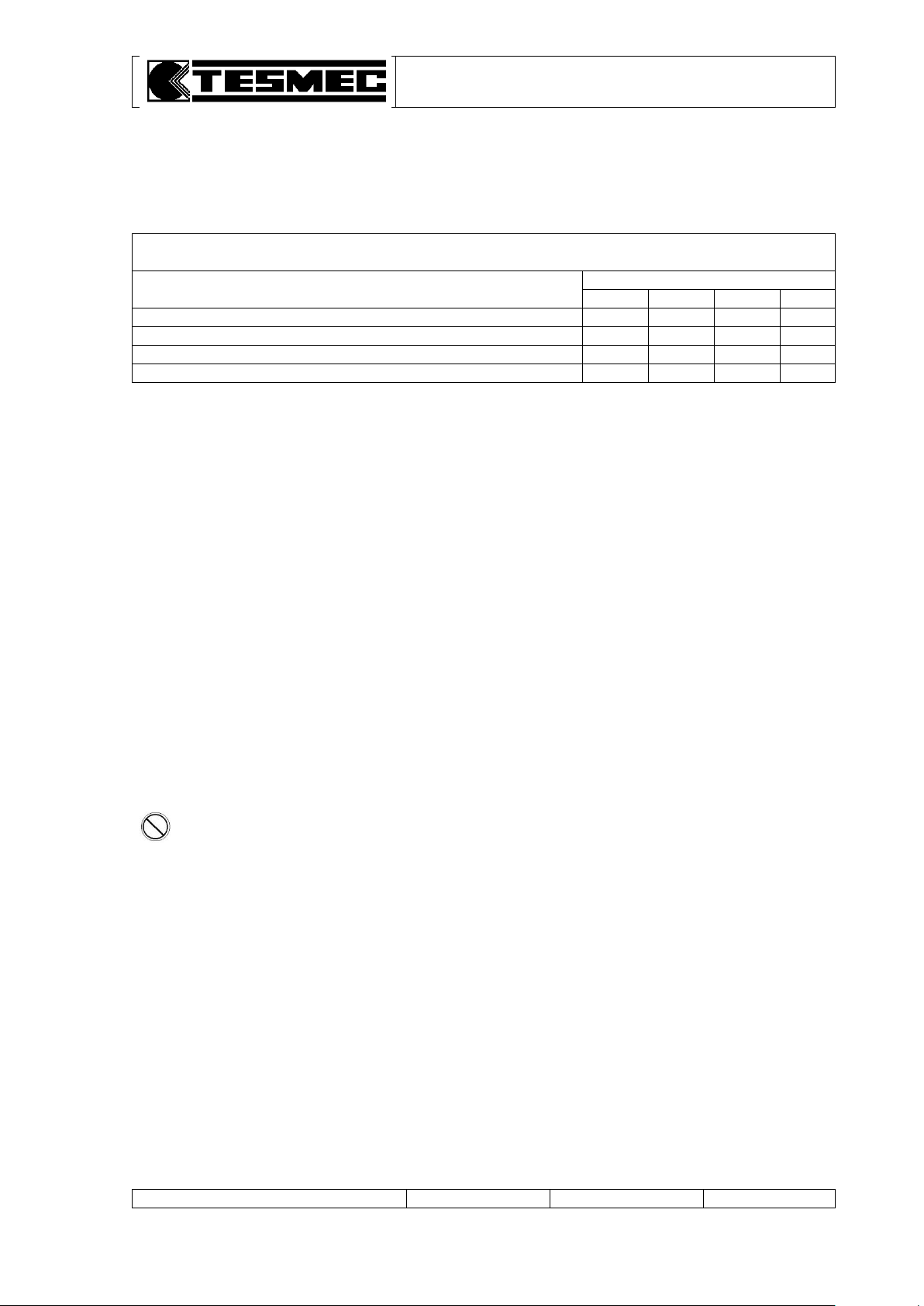
TEMPERATURE LIMITS FOR HYDRAULIC OIL (°C)
Working condition
Hydraulic oil viscosity
VG 22
VG 32
VG 46
VG 68
Minimum temperature running in neutral position
-21
-14
-7
-1
Minimum temperature running in full load
8
16
24
32
Maximum temperature running in full load
48
57
67
76
Maximum temperature running in neutral position
63
73
83
93
PROHIBITION: is not allowed to install on board radio equipments. These could create
electronic equipment malfunctions, putting the personnel at serious risk.
2.12 TEMPERATURE LIMITS FOR HYDRAULIC OIL
When using the machine, always remember to respect the following temperature limits that can be
reached with hydraulic oil as function of the working condition.
For additional information concerning the hydraulic oil, see chapter "Maintenance" and the attached
comparative table of the oils used on the machine.
2.13 USE NOT ALLOWED
The machine must not be used:
a. for lifting persons and/or goods
b. in grounds on which the machine cannot be positioned and anchored in a proper way
c. in areas with brushwood or other materials presence that can be easily set on fire
d. in closed/unventilated sites or, however, not sufficiently airy (tunnel or similar)
e. in sites with presence of gas that can be easily set on fire or explosives
f. in sites with presence of explosive materials
g. on aircraft, crafts, floating platforms and similar
h. for structure demolition, shafts felling or similar
i. for pulling flexible elements that can be highly lengthening, which allow elastic power accumulation
j. with ropes or joints having a bigger diameter than the one specified in present manual
k. when engine is off and adherence units are moving
l. with inhibited and broken safety devices installed on the machine
m. when winding on the bull-wheels ropes and/or conductors having a smaller diameter as a
succession of ropes and/or conductors having a bigger diameter
n. for handling trucks or other moving equipment.
Page 10

PULLER-TENSIONER
Model: AFS303
Manual: MI-AFS303-320-00-GB
Date: 30.03.2015
Author: MC
Page: 7 of 32
2.14 RESPONSIBILITY
The use of the machine for scopes different from those foreseen on paragraph 2.3 (Typology and
using field), even if not well described in this manual, has to be considered extremely dangerous and
then forbidden.
The non-respect of the prescribed restrains causes a situation of improper use for technical
and persons safety purposes and relieve the manufacturer from any responsibility, civil or
penal, in case of accidents to persons or damages to things, causing the loss of warranty.
The manufacturer responsibility declines even when one of the following situations happens:
a. for the consequences caused by tampering and/or modifications carried out without the
manufacturer’s written acceptance (in this case the operator becomes the manufacturer with
relevant obligations and responsibilities, both civil and penal)
b. for the use of not original spare parts
c. or bad maintenance
d. for the use with disconnected safety devices
e. for the connection to machine and/or plans not produced and not directly authorised by the
manufacturer in a written acceptance.
2.15 APPLIED NORMS
If the machine is commercialized in C.E. responds to the following regulatory framework:
2006/42/CE Norm of the European Parliament and Council referring to the laws of the machines
member States.
2004/108/CE Norm of the European Council referring to the laws of the electromagnetic
compatibility member States.
If the machine is commercialized outside the C.E. was made reference to the following regulatory
framework:
2006/42/CE Norm of the European Parliament and Council referring to the laws of the machines
member States.
2004/108/CE Norm of the European Council referring to the laws of the electromagnetic
compatibility member States.
Page 11
PULLER-TENSIONER
Model: AFS303
Manual: MI-AFS303-320-00-GB
Date: 30.03.2015
Author: MC
Page: 8 of 32
DANGER: the non-respect of the above mentioned conditions may cause dangerous
situations as well as damages to the machine with the consequent decline of any warranty
condition.
ATTENTION: the elimination of packaging materials must be effectuated in conformity with the
norms in force in the relevant country.
3. TRANSPORT AND POSITIONING INSTRUCTIONS
3.1 MACHINE LIFTING
For the machine lifting use only devices as overhead travelling cranes or lift trucks, with a capacity
equal to the mass to be lifted.
The instruments used for the machine lifting (ropes, cables, hooks, etc.) have to be exactly
dimensioned as compared to the mass to be lifted and have to be connected to the proper elements
foreseen on the machine (table 1, pos. 2).
During machine lifting operations, the presence of persons on the machine is strictly forbidden.
3.2 TRANSPORT TYPOLOGIES AND PACKAGE
Transport by land by truck
The machine comes without all the liquids that can be set on fire and protected in the most exposed
and delicate parts by means of cardboard and/or plywood and/or polyethylene extensible film.
To fix the machine on the platform of the transporting unit, use nailed wedges and/or metal brackets
and/or tie rods.
Transport by sea in wooden cases or container
The machine comes without all the liquids that can be set on fire; metal parts are protected with
waterproof wax.
To fix the machine on the package, use nailed wedges and/or metal brackets and/or tie rods.
At the inside, the wooden case foreseen a protection with tarpaper.
Materials usually used for the package are:
wooden
nails and/or steel screws
cardboard and/or paper
polyethylene extensible film
adhesive tape.
3.3 UNPACKING
When receiving the machine verify the integrity of the package; advise immediately the manufacturer
and the person in charge of the transport (even with photos) when possible damages due to transport
or tampering with removal, even partial, of the content happen.
Verify if the supplied material corresponds to the ordered one; immediately advise the manufacturer if
there are some discrepancies.
In case of transportation on wooden case, take away, in sequence, the upper cover and lateral panels,
before removing the machine.
During unpacking operations, avoid any shock to the structure or to the machine units, in order to
avoid any damage to the machine itself.
Page 12
PULLER-TENSIONER
Model: AFS303
Manual: MI-AFS303-320-00-GB
Date: 30.03.2015
Author: MC
Page: 9 of 32
ATTENTION: dangerous situations during towing if the tyres inflation pressure and the speed
limit are not respected may happen.
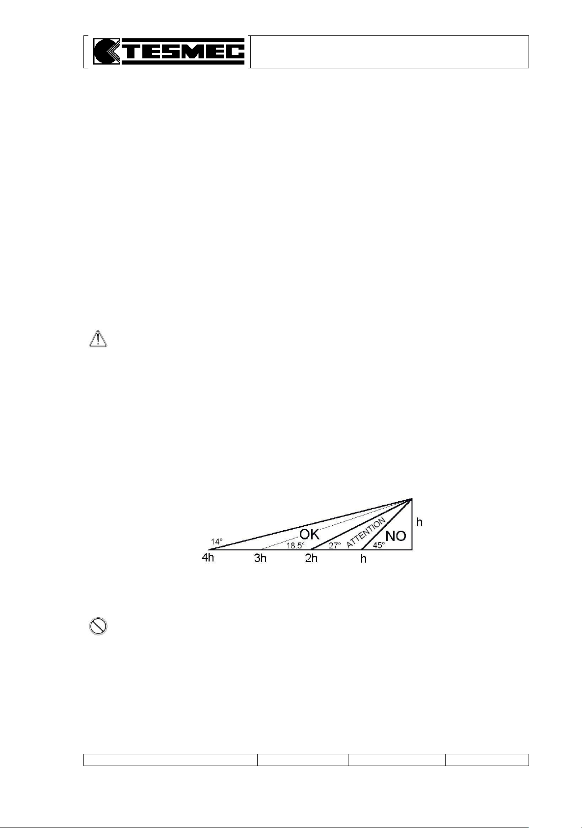
PROHIBITION: when the distance between the machine and the pole is lower than the
height of the pole itself, the machine use is not possible.
3.4 ASSEMBLING OPERATIONS
Mount the tyres in the suitable holes.
3.5 TRANSPORT ON TRAILER
Machine is not suitable for road towing.
Possible displacements on trailer in the working site must be carried out by a connection to the towing
unit by means of the towing eye on the drawbar (table 1, pos. 6) and in the respect of the speed limits
of the axle. The used towing unit must be homologated for towing trailers with mass and dimensions
as per the described machine.
Before transporting operation, lift the rear stabiliser (table 1, pos. 11) and the front plough
(table 1, pos. 5) acting on the lever (table 3, pos. 29) (NOTE: during this operation the diesel engine
has to be always started-up).
Check the inflation pressure of tyres (5 bars).
During trailer machine transport operations is nobody must stay in the machine itself.
When transporting on truck or trailer, verify if the machine has been fixed on the platform with nailed
wedges and/or metal brackets and/or tie rods.
3.6 POSITIONING AND ANCHORING
Positioning and anchoring of the machine have to be carried out only by trained personnel, verifying if
the ground grants the foreseen stability, support and anchoring.
The machine has to be placed in a distance from the first pylon or trestle for the rope passage (or
conductor) included between 2 and 4 times the height h of the pylon itself (see diagram here below).
It is possible to use the machine at a distance from the pole included between 1 and 2 times the height
of the pole itself. In this case, the anchorage described thereafter must be over dimensioned of 125%
compared to the reported data and some moorings must be provided on the front side of the machine.
Page 13
PULLER-TENSIONER
Model: AFS303
Manual: MI-AFS303-320-00-GB
Date: 30.03.2015
Author: MC
Page: 10 of 32
ATTENTION: the non-respect of the foreseen anchoring operations may cause dangerous
situations during machine use.
DANGER: machine has not a proper grounding device; for the system machine-ropeconductor in the job site must foreseen a grounding device on the towing rope or on the
conductors.
Machine anchoring sequence is the following:
a. machine must be aligned as much as possible with the pull direction.
b. position the rear stabiliser (table 1, pos. 10) and then load properly the plough (table 1, pos. 5)
operating on the lever (table 3, pos. 29) (NOTE: during this operation the diesel engine has to be
always started-up).
c. anchor the machine to the ground by means of 2 stakes with min. granted load equal to 130% of
the machine max. pull, connecting the foreseen connections (table 2, pos. 3) with the anchoring
stakes and respecting the described scheme and angles (table 2).
d. recover the clearance on the anchoring stakes without tensioning them.
e. test the machine pull (see use instructions on the following chapter) to allow the machine to freely
align as regards as the pull itself.
f. tension the anchoring stakes in a uniform way.
g. block the machine brakes acting on the special hand-wheel (table 1, pos. 9).
Around the machine must be a free space of at least 2-m to make easier the operations of use,
adjustment, maintenance, etc.
Be sure that around the radiator (endothermic engine, hydraulic oil) cooling air can freely circulate.
Otherwise overheating situations with damage for the installed components may happen.
Page 14
PULLER-TENSIONER
Model: AFS303
Manual: MI-AFS303-320-00-GB
Date: 30.03.2015
Author: MC
Page: 11 of 32
PROHIBITION: it is forbidden to walk or stop in front or backward the machine and/or under
the towing rope due to a constant residual risk of crushing in case of a possible giving in of the
rope or of the anchoring.
NOTE: when using the machine at room temperature between -10°C and -20°C it is
necessary to carry out the preheating sequence as indicated at paragraph 4.10 and
4.11.
ATTENTION: do not use excessively lubricated or greased ropes because possible
adherence problems on the bull-wheels with a consequent sliding of the ropes
themselves may arise.
NOTE: the stringing speed can be read on the manometer scale relevant to the selected
reduction ratio.
ATTENTION: this operation must be made only with stopped machine and without
applied loads.
PROHIBITION: when you position the mechanical transmission control lever on the low
pull (table 2, pos. 9B) on the panel switch on the red light (table 3, pos. 23), which
advise that the machine cannot absolutely be used as puller but only as tensioner.
DANGER: please pay attention to the risk to be squeezed during the operations above
described.
4. INSTRUCTION FOR USE
4.1 PRESCRIPTIONS FOR THE OPERATOR
Daily, before starting the work, check:
a. if the protection and safety devices are activated and functioning
b. if the connections with power unit are in good conditions
c. if the machine liquids levels are in conformity with the indications in maintenance chapter
d. if the anchoring conditions are in conformity with the indications of present manual.
4.2 CONTROLS
Position and meaning of the elements on the control board are described on table 3 enclosed.
4.3 PRELIMINARY OPERATIONS
a. Load the conductors or the cables on the bull-wheels as shown on tables 2 and 4 positioning the
entering guide-rope rollers in the proper position.
b. Lubricate the gears before each starting of the machine using the proper greasers (table 2, pos. 2).
c. Position the lever of mechanical transmission (table 2, pos. 9) into the proper ratio in accordance
with the job to do:
pos. C: high pull (tension higher than 4kN) (normal braking)
pos. B: low pull (tension lower than 4kN) (fine braking)
Page 15
PULLER-TENSIONER
Model: AFS303
Manual: MI-AFS303-320-00-GB
Date: 30.03.2015
Author: MC
Page: 12 of 32
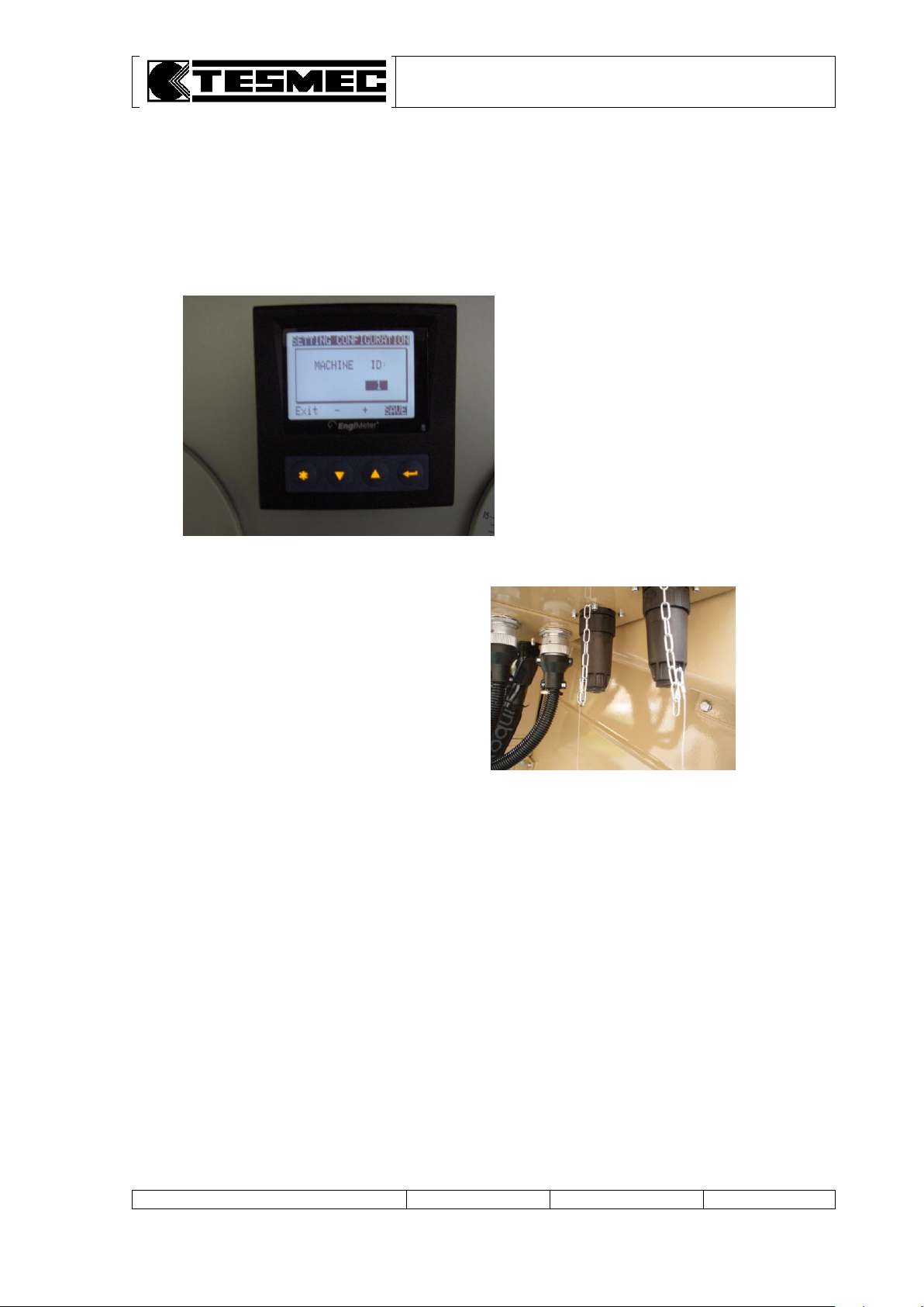
NOTE: in case of stand-alone
using mode the ID of the machine
must always be set at 1
When the machine is used in stand-alone
configuration the two plug connectors must be
closed with the related caps
4.4 MACHINE SET-UP
Before the use, the machine must be set in stand-alone using mode, operating on the control panel
(table 3).
a. insert and turn the ignition key (table 1, pos. 14) in "1" position
b. wait up to the multifunction display switch on
c. on the electronic multifunction display press the () key
d. on the screen page “MACHINE ID:” set the number “1” by using the up () or down () key
press the return key ( ) to save the settings
Page 16
PULLER-TENSIONER
Model: AFS303
Manual: MI-AFS303-320-00-GB
Date: 30.03.2015
Author: MC
Page: 13 of 32
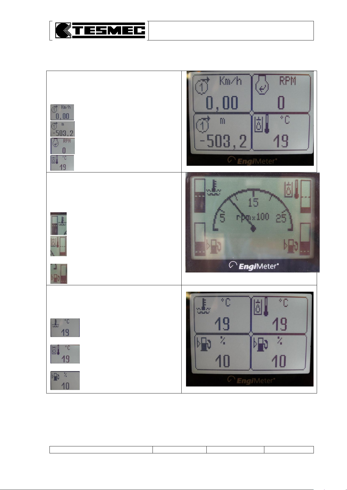
1. METER COUNTER & SPEED PAGE
This page shows the speed and the meter
counter for each independent circuit
speed of capstan nr.1
meter counter of capstan nr.1
RPM diesel engine
hydraulic oil temperature
2. RPM & DIESEL ENGINE PAGE
This page shows the rpm of the diesel engine in
the center and 4 percentage check icons on the
edges:
diesel engine water cooling temperature
hydraulic oil temperature
diesel engine fuel level
3. DIESEL ENGINE DATA PAGE
This page shows 4 percentage check icons of
diesel engine data:
.diesel engine water cooling
…...temperature
hydraulic oil temperature
diesel engine fuel level
4.5 ELECTRONIC MULTIFUNCTION DAVICE PAGES
The electronic multifunction display shows 4 working pages:
Page 17
PULLER-TENSIONER
Model: AFS303
Manual: MI-AFS303-320-00-GB
Date: 30.03.2015
Author: MC
Page: 14 of 32
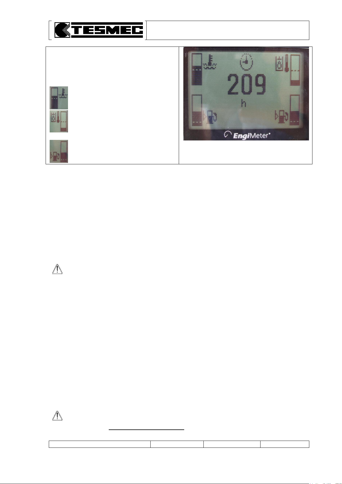
4. HOUR COUNTER PAGE
This page shows the working hour of the diesel
engine in the center and 4 percentage check
icons on the edges:
diesel engine water cooling temperature
hydraulic oil temperature
diesel engine fuel level
ATTENTION: when starting a cold machine, after heating the hydraulic oil as previously
described, begin stringing operations limiting the maximum working performances for
at least the first 15 minutes, that means to keep at half accelerator the Diesel rpm and
don’t exceed the 30% of the maximum stringing speed.
DANGER: when using a machine as tensioner, position the pull limiting device
(table 1, pos. 20) on the maximum scale, to avoid dangerous stopping.
This operation is absolutely indispensable when the machine “tensioner” works with a
puller without pull limiting device.
Switch from one page to the other one by using the up () or down () key.
4.6 STARTING OF THE MACHINE
a. Operate from the principal control panel (table 1).
b. Position to centre the control lever of the variable delivery pump.
c. Turn of one point the starting key (table 1, pos. 14).
d. Push and turn up to starting the starting key (table 1, pos. 14) and simultaneously keep the lever
(table 1, pos. 4) lowered.
The lever (table 1, pos. 4) must be lowered for a few seconds after the engine start-up.
e. Regulate the rpm with the accelerator (table 1, pos. 12).
f. Verify that the pressure indicate on the feeding manometer (table 1, pos. 7) is more than 20 bars
with minimum rpm; on the contrary stop the machine.
4.7 PULL CONTROL
The machine is equipped with two pull control devices for the control of the max. pull value on the line:
1. PULL LIMITING DEVICE that stops the machine when reaching the max. pull
2. PULL PROGRAMMING DEVICE that stops only the bull-wheels rotation keeping the diesel engine
turned-on when reaching the max. pull.
4.7.1 PULL LIMITING DEVICE SETTING
Completely turn right the knob (table 1, pos. 6).
With the suitable pawl, connected to the dynamometer move the red arrow in correspondence of
the max. pulling value that has not to be exceeded.
When the pre-set pull value is reached, the machine stops automatically and the diesel engine turns
off while the negative brakes automatically insert with the consequent stop of the bull-wheels
rotation. When the pull value is exceeded the warning light (table 1, pos. 20) on the control panel
turns on.
Page 18
PULLER-TENSIONER
Model: AFS303
Manual: MI-AFS303-320-00-GB
Date: 30.03.2015
Author: MC
Page: 15 of 32
ATTENTION: THE OPERATIONS TO SET THE PULL MUST BE CARRIED OUT WITH
STARTED DIESEL ENGINE BUT WHEN THE MACHINE IS TURNED OFF.
ATTENTION: the red arrow of the pull limiting device has to be positioned at a higher
value than the one pre-set with the PULL PROGRAMMING DEVICE to avoid the machine
stop.
DANGER: when using a machine as tensioner, position the pull limiting device
on the maximum scale, to avoid dangerous stopping.
This operation is absolutely indispensable when the machine “tensioner” works with a
puller without pull limiting device.
ATTENTION: after finishing the above mentioned operations and beginning stringing
operations, it is important not to touch the knob (table 1, pos. 6).
In fact, should the knob be rotated while the machine is stringing, this operation
cancels the previous carried out calibration and the systems set on the new values
congruent with new position of the knob.
Then, avoid this operation, using it only in emergency situations.
ATTENTION: before starting the work, check if the selector (table 1, pos. 5) is on
position . It is forbidden to move the selector (table 1, pos. 5) during working
operations because dangerous situations because the machine immediately stops may
happen.
ATTENTION: the dynamometer is calibrated with 3 scales: puller, tensioner and fine
braking. Read the desired values in function of the operations to be carried out (pulling
or tensioning).
4.7.2 PULL PROGRAMMING DEVICE SETTING
Start the diesel engine and set the engine at about 1600 rpm.
Move the selector (table 1, pos. 5) on position (rightwards).
Gently move towards (downwards) the lever (table 1, pos. 4).
Turn the knob (table 1, pos. 6) till on the manometer ring nut (table 1, pos. 1) can be read the pull
value that must not be exceeded.
Gently move the lever (table 1, pos. 4) to central position (neutral position).
Re-place the selector (table 1, pos. 5) on position (leftwards).
Once reached the set pull the bull-wheels automatically stop without the diesel engine turning off
with the consequent machine stop. The bull-wheels will remain stopped till when the cause which
tried to raise the pull over the imposed value is removed (line obstacles, increase of friction on the
pulleys, braking mistakes, etc.).
Page 19
PULLER-TENSIONER
Model: AFS303
Manual: MI-AFS303-320-00-GB
Date: 30.03.2015
Author: MC
Page: 16 of 32
ATTENTION: it is important that, before connecting the rapid connections, the operator
has checked their cleanliness as the introduction of dirt into the hydraulic circuit can
create very serious damages.
ATTENTION: the rapid connections must be connected before to put in pressure the
circuit.
ATTENTION: the cocks must be opened when connecting the hydraulic heads (or reel
winders).
ATTENTION: before carrying out any operation it is necessary to verify if the selectors
(table 1, pos. 5 and 27 – optional) are turned towards leftwards .
NOTE: the adjusting valve (table 3, pos. 10) regulates the pressure of the two circuits of
the reel elevators/reel winders, at the same time.
ATTENTION: it is important that this value is regulated at the minimum necessary value
in function of the operations that we must carried out (recovery or stringing).
In particular, during the final regulation of the bull-wheels, it is necessary to raise the
pressure when we recover and lower it when we string: on the contrary, due to the
mechanical and hydraulic efficiency, with the same set pressure we will have very
different pulls back.
ATTENTION: the red arrow of the dynamometer (table 1, pos. 1) has to be positioned at
a value higher than the one set with the knob (table 1, pos. 6).
ATTENTION: after starting stringing operations, it is important not to turn the knob
(table 1, pos. 6). In fact, should the knob be rotated while the machine is stringing, this
operation cancels the previous carried out calibration and the systems set on the new
values congruent with new position of the knob.
4.8 CONNECTION MACHINE-HYDRAULIC HEAD OF THE REEL ELEVATOR OR REEL
WINDER
Each hydraulic head (or each reel-winder) has a connecting kit consisting of two pipes.
Each of these pipes has to be connected at the proper rapid connection taking care to connect them
properly (otherwise the installation will not work).
4.9 PULLING OPERATIONS
a. Adjust the rpm of the diesel engine using the accelerator (table 1, pos. 12): puller – 2600-rpm max.,
tensioner – 1800/2000 rpm. The number of rpm can be read on the instrument on the panel
(table 1, pos. 17).
b. Adjust the feeding pressure of the hydraulic heads connected to the machine by the valve
(table 1, pos. 10) and read the correspondent value on the manometer (table 1, pos. 11).
When using the machine as puller, the pressure of the hydraulic heads will be from 60 bars (reels
with few turns) till a max. value of 120-130 bars (full reel).
Using the machine as tensioner, the pressure of the hydraulic heads can be set at 60-70 bars.
c. Gently move the control lever of the pump (table 1, pos. 4) towards downwards .
Now the machine is ready to work: if the tension is higher than the set working value, the machine
operates as tensioner. If the tension is lower than the set working value, the machine operates as
puller. The machine is completely automatic, for this reason when setting a pulling value, the machine
works as puller or as tensioner following the motions of the opposite machine.
d. To stop the bull-wheels rotation, move the lever towards centre position (table 1, pos. 4).
Page 20
PULLER-TENSIONER
Model: AFS303
Manual: MI-AFS303-320-00-GB
Date: 30.03.2015
Author: MC
Page: 17 of 32
ATTENTION: do not quickly move the lever (table 1, pos. 4) towards centre position
because a fast connection of the negative brakes that might produce dangerous
damages to the disks mounted inside the brakes may happen.
ATTENTION: the connection of the rapid couplers has to be effectuated with the lever
(table 6, pos. 4) in "B" position to discharge the pressure in the hydraulic circuit.
If there is residual pressure in the hydraulic circuit, it is not possible to connect and
disconnect the rapid couplers.
During stringing operations, the strung meters can be read on the relevant indicator.
The indicator can be set to zero by pressing the push-button “RESET”.
During functioning operations, verify that:
a. the hydraulic oil temperature, shown on the thermometer (table 1, pos. 16), doesn’t exceed 80°C.
This is the maximum acceptable value for the hydraulic components in case the oils suggested by
Tesmec are used. If other kinds of oils are used, the maximum acceptable working temperature
depends on their characteristics in relation also to the viscosity limits imposed by the hydraulic
pumps and motors.
b. the warning lights of the electric clogging indicators mounted on the control board
(table 1, pos. 24 and 25) don’t switch on when the hydraulic oil reaches the working temperature.
However, it may happen that the lights indicate clogging even if it doesn’t occur (especially at very
low outside temperatures). In this case, see point e) paragraph 4.4 and wait for the lights to turn off
before making the bull-wheels run.
4.10 RELEASING THE ROPE
The rope or the conductor can be released, not under load, moving the lever (table 1, pos. 4) upwards
.
4.11 COMPRESSOR CONNECTION (OPTIONAL)
The machine has been studied to be connected to a Tesmec compressor.
a. Connect the rapid couplers (table 6, pos. 5 and 6).
b. Start the machine, turn the selector (table 1, pos. 27) towards right position and close the valve
(table 1, pos. 8).
c. Lower the lever (table 6, pos. 4) in "A" position.
d. Adjust the functioning pressure of the compressor using the valve (table 6, pos. 1).
The pressure can be read on the manometer (table 6, pos. 2).
Once ended the compressing operations, to use the machine act as follows:
a. turn the valve (table 6, pos. 1) and lower the pressure in the compressor.
b. lift the lever (table 6, pos. 4) in "B" position.
c. open the valve (table 1, pos. 8).
d. turn the selector (table 1, pos. 27) towards left position .
e. remove the rapid couplers (table 6, pos. 5 e 6).
Page 21
PULLER-TENSIONER
Model: AFS303
Manual: MI-AFS303-320-00-GB
Date: 30.03.2015
Author: MC
Page: 18 of 32
ATTENTION: before starting the preheating system, check if the two cocks are on
WINTER position. On the contrary, the preheating system doesn't work and may be
damaged.
ATTENTION: when the diesel engine is working, the preheating kit has to be switched
off.
ATTENTION: for using the heater, the pump blow-by selector has to be on automatic
position (leftwards).
4.12 PREHEATING KIT (OPTIONAL)
The machine is equipped with a preheating kit to be used when room temperatures are included
between -10°C and -20°C.
This kit is composed by a gas-oil burner and by an heating circuit that uses the cooling liquid of the
diesel engine: the consumption heated by the preheating kit are the diesel engine block, the hydraulic
oil tank, the diesel engine gas-oil tank and the delivery of the gas-oil to the diesel engine.
The gas-oil for the preheating kit burner has to have the following technical specifications (DIN 51601):
70% winter gas-oil
30% petroleum or kerosene
In case of temperatures higher than -10°C, or whatever when the preheating system is not used, set
the two cocks for the preheating circuit cut out (table 8, pos. 3-5) on SUMMER position, while when
the preheating system is used, set the cocks on WINTER position.
To start the preheating system, push the push-button on the control panel: the system starts
automatically.
Once stopped the preheating system and with functioning diesel engine, if the operator wishes to heat
the gas-oil and hydraulic oil tanks, it is possible to activate the liquid blow-by pump acting on the
selector – manual position (rightwards).
Please consider that the heater liquid reaches the service temperatures in about 20 functioning
minutes, while after 30 functioning minutes of the heater, the temperature of the hydraulic oil in the
relevant tank increases of about 10°.
4.13 PREHEATING CONTROL PANEL PROGRAMMING (OPTIONAL)
4.13.1 GENERAL (OPTIONAL)
The standard digital timer/combination timer enables to pre-set the start of the heater operation up to 7
days in advance. It is possible to program 3 different starting times, only one of which can be
activated. The standard digital timer features a wakeup alarm function.
When the ignition switched on, the timer displays the current time and the day of the week.
When the heater is switched on, the display and the buttons are illuminated.
After the power supply has been connected, all symbols on the display will flash.
The current time and weekday must be set.
4.13.2 OPERATION (OPTIONAL)
The timer can be operated so that all flashing symbols can be adjusted by means of the and
Page 22
PULLER-TENSIONER
Model: AFS303
Manual: MI-AFS303-320-00-GB
Date: 30.03.2015
Author: MC
Page: 19 of 32
buttons. If the buttons are not pressed within 5 seconds, the time displayed will be stored.
If the and buttons are pressed for more than 2 seconds, the fast time-setting mode is
activated.
If the ignition is switched off while the heater is operating in the continuous mode, the remaining
operating time of 15 minutes is displayed and the heater continues to operated for this period of time.
4.13.3 SWITCHING THE HEATER ON (OPTIONAL)
Manually: by pressing the button (continuous heating mode).
Automatically: by programming the heater starting time.
4.13.4 SWITCHING THE HEATER OFF (OPTIONAL)
Manually: by pressing the button .
Automatically: after the programmed operating time has elapsed.
With the heater running: by programming the remaining operating time.
4.13.5 SETTING TIME/DAY OF THE WEEK (OPTIONAL)
Press the button for more than 2 seconds – time of the day is flashing.
Set the clock using the and buttons – day of the week is flashing – adjust the day of the week.
4.13.6 VIEWING THE TIME (OPTIONAL)
With the ignition switched off: press the button.
4.13.7 PROGRAMMING HEATER STARTING TIME (OPTIONAL)
Press the button – the memory location is flashing – using the and buttons set start of the
heater operating time. Day of the week is flashing – set the day of the week.
By repeatedly pressing the button, memory locations 2 and 3 can be programmed or the time
display mode can be reached.
4.13.8 RECALLING/ERASING PRE-SET TIMES (OPTIONAL)
Repeatedly press the button until the desired memory location is displayed.
To erase the pre-set time, press the button several times until the time of the day is displayed
instead of the memory location.
4.13.9 PROGRAMMING DURATION OF OPERATING TIME (OPTIONAL)
The heater must be switched off. Press the button for 3 seconds – operating times is flashing –
and set the desired operating time (10 to 120 minutes) using the and buttons.
4.13.10 SETTING THE REMAINING OPERATING TIME (OPTIONAL)
Set the desired remaining operating time (1 to 120 minutes) using the and buttons.
The remaining operating time refers to the time the heater still continues to remain in operation.
It can only be changed while the heater is in operation and the ignition switched off.
4.13.11 SETTING THE WAKEUP TIME (OPTIONAL)
A wakeup time can only be programmed on the standard digital timer.
Page 23
PULLER-TENSIONER
Model: AFS303
Manual: MI-AFS303-320-00-GB
Date: 30.03.2015
Author: MC
Page: 20 of 32
The wakeup time is not bound to a specific day of the week.
Repeatedly press the button until the bell symbol appears on the display.
Set the desired wakeup time using the and buttons.
The alarm clock turns off after 5 minutes or when one of the buttons is pressed.
4.13.12 RECALLING/ERASING THE WAKEUP TIME (OPTIONAL)
Repeatedly press the button until the bell symbol appears on the display – read off wakeup
time. To erase the wakeup time: press the button until the bell symbol is no longer visible on
the display.
4.14 ROPE LOCKING CLAMP (OPTIONAL)
The rope locking clamp allows blocking the rope end towards the reel winder and therefore the
operations for removing the reel are speed up.
The rope locking clamp can be connected acting on the selector (table 3, pos. 30).
To engage the rope locking clamp, turn the selector (table 3, pos. 30) on position (blocked).
When the machine is working the selector has to be turned on position (free).
4.15 POINTS TO REMEMBER
a. The pressure of feeding circuit (table 1, pos. 7) must be more than 20 bars: otherwise, the
stationary brakes could be damaged.
b. Adjust the pull of reel elevators with hydraulic head (table 1, pos. 10) at minimum indispensable
value: otherwise, the hydraulic oil could be heated and dangerous counter pulls may arise.
c. In hot climates, during the stoppages, let running the Diesel engine with the radiator fan connected
(table 1, pos. 8) at maximum speed.
d. Before beginning the works, check the levels.
e. Respect the temperature limits for the hydraulic oil as indicated at paragraph 2.12.
f. Check the condition of the discs in the emergency brakes after any emergency intervention.
g. Remember to use the values indicated on the scale “puller” for the recovery phases and those
indicated on the scale “tensioner” for the stringing phases.
h. When we use the machine as tensioner, position the pull limiting device – red arrow (table 1, pos.
20) on the minimum scale, to avoid dangerous stopping.
This operation is absolutely indispensable when the tensioner machine work with a puller without
automatic limiting pull device.
i. The connecting operations of the mechanical reduction gear (table 2, pos. 9) must be made only
with stopped machine and not under charge.
4.16 END OF THE OPERATIONS
At the end of the operations, discharge the ropes-conductors tension using the control lever
(table 1, pos. 4). Then stop the engine operating on the starting key.
Page 24
PULLER-TENSIONER
Model: AFS303
Manual: MI-AFS303-320-00-GB
Date: 30.03.2015
Author: MC
Page: 21 of 32
5. INSTRUCTION FOR USE – CONNECTED MACHINES
5.1 GENERAL ASPECTS
This machines could be equipped with an electronic connection package as an optional device.
This device allow to use multiple machines connected between them, controlled and operated by a
single operator for the main working parameters (basically speed, pull, diesel engine rpm).
Is possible to connect a maximum 12 machines between them, with the possibility to work with 12
independent ropes configurations.
Tesmec suggest to use this configuration device on machine working at the puller station, to allow to
recover multiple ropes or conductors with the same speed.
The machines must be numbered with ID number (see next chapter) from 1 to the number of total
connected machines starting from right to left, looking at the machines from the back (reel-winder
position). The last machine, positioned on the right, is the master machine. See table 10 as example.
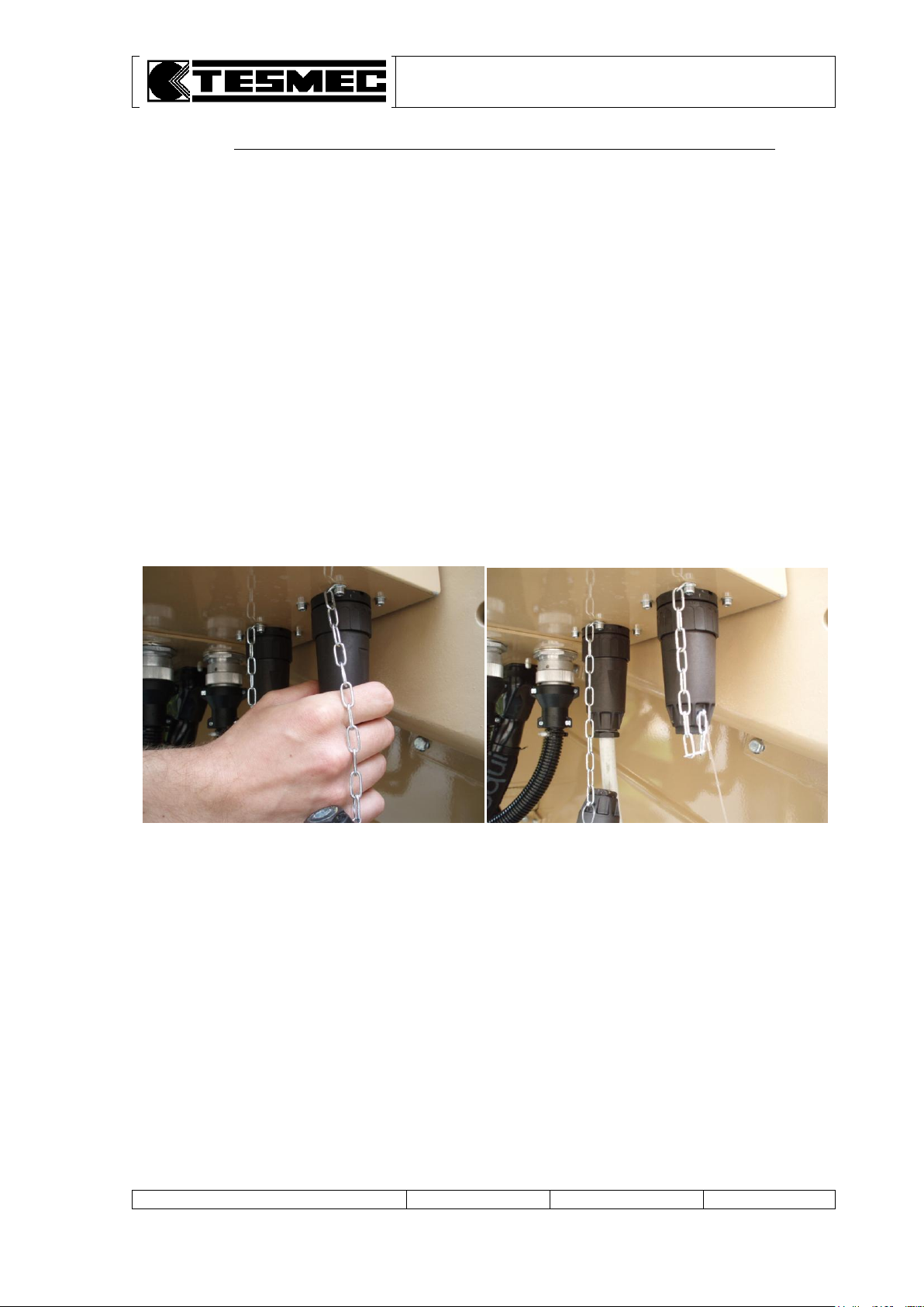
The machines must be connected through a special connecting cable; the un-used plugs on the first
and on the last machine (right and left) must always be closed with the related caps.
To grant the continuous connection of the machines, a special protection device must be provided for
the connection cables, to avoid accidental disconnection of the communication between the machines.
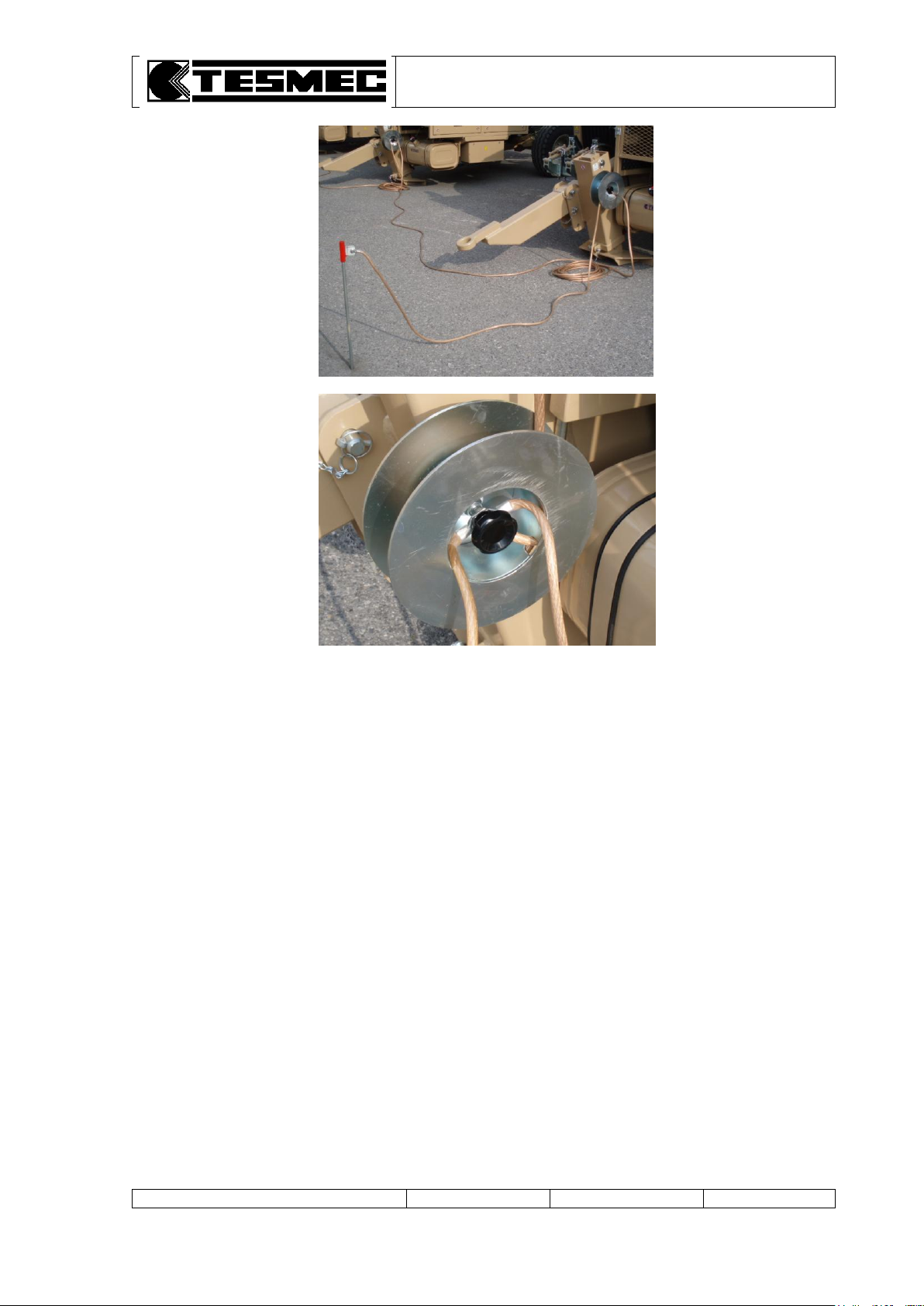
It is necessary to provide a correct grounding of each machine, to avoid trouble at the electronic
devices. For this reason each machine is equipped with a special grounding device that must be
connected prior to switch on each machine.
The correct grounding configuration is realized with a grounding stakes (see table 9) to be placed on
the ground in front at the machine, and a connecting ground cable, that must connect all the ground
stakes between them.
Page 25
PULLER-TENSIONER
Model: AFS303
Manual: MI-AFS303-320-00-GB
Date: 30.03.2015
Author: MC
Page: 22 of 32
Prior to operate the set-up of the machines, check that:
The machines are connected through the special connecting cable
The ground devices are installed and connected
The gear-box configuration is HIGH-PULL in each machine (optional)
5.2 MACHINES SET-UP
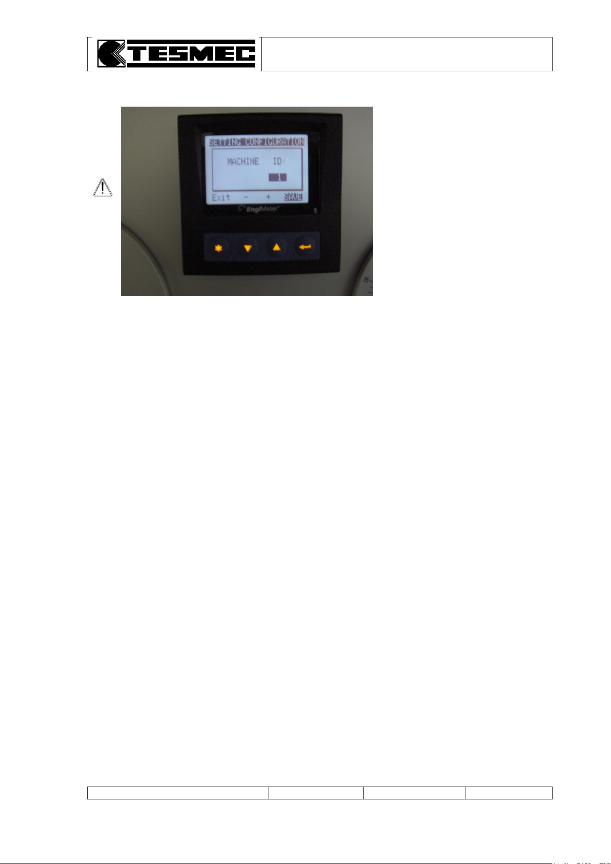
Before the use the machine must be set in connected mode by assign to each machine the correct ID
number, starting from left to right, as described in the previous chapter.
a. insert and turn the ignition key (table 3, pos. 14) in “1” position
b. wait up to the multifunction display switch on (table 3, pos. 17)
c. on the electronic multifunction display press the () key
d. on the screen page “MACHINE ID:” set the correct number by using the up () or down () key
e. press the return key ( ) to save the settings
Page 26
PULLER-TENSIONER
Model: AFS303
Manual: MI-AFS303-320-00-GB
Date: 30.03.2015
Author: MC
Page: 23 of 32
NOTE: the ID of the machines
must be set from 1 to the total
number of connected machines
starting from left to right (looking
at the machines from the back –
reel-winder position)
e. set each machine in connection configuration, except the final one, by turning rightwards the
selector (table 3, pos. 3).
5.3 CONNECTED MACHINES OPERATIONS
When using connected machines, the following controls effect on all machines when operated from
the master machine:
Speed control (joy-stick)
Pull-adjusting control (potentiometer)
Negative brake open – close selector
Diesel engine accelerator
Rope-clamp selector
When using connected machines, the following controls must be operated on each single machine:
Reel-winder working pressure
Reset of meter counter
Pull limiting device in the dynamometers
Main front plough position
5.4 PULL CONTROL SETTING
5.4.1 PULL LIMITING DEVICE SETTING
With the suitable pawl, connected to the dynamometers (table 3, pos. 12), move the red arrow in
correspondence of the max. pulling value that has not to be exceeded.
The pre-set value must be the same for all the machines connected, and must be set on each single
machine.
5.4.2 PULL PROGRAMMING DEVICE SETTING
The setting must be operated at the circuit of the last connected machine and will effect on all the
machines.
The operation sequence is the same described on the stand alone using mode chapter 4.7.2.
Page 27
PULLER-TENSIONER
Model: AFS303
Manual: MI-AFS303-320-00-GB
Date: 30.03.2015
Author: MC
Page: 24 of 32
The machine could be provided with an
electronic speed synchronizer device as a
optional package; to activate operate on the
selector (table 3, pos. 9) (rightwards) on the
master machine.
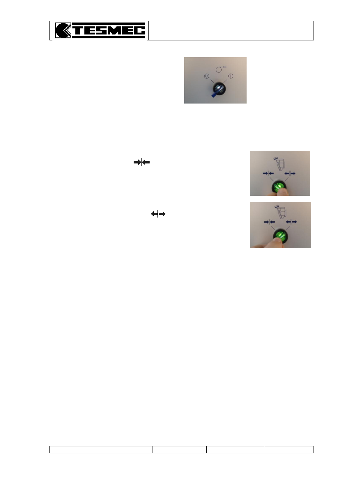
To engage the rope locking clamp, turn the proper selector on the master
machine (table 3, pos.30) on position (leftwards - blocked – no
light) and keep it in position for a few second to allow the complete closing
of the clamp.
To dis-engage the rope locking clamp, turn the proper selector on the
master machine (table 3, pos.30) on position (rightwards – free –
green light) and keep it in position for a few second to allow the complete
opening of the clamp.
When using connected machines some situation generate alarm condition
with switch on of the alarm light on the main control panel of the machine
where the alarm is generated.
5.5 USING OF ELECTRONIC SPEED SYNCHRONIZER DEVICE (OPTIONAL)
This device allow to have the same recovering speed of each connected machines.
5.6 ROPE LOCKING CLAMP (OPTIONAL)
When the machine are connected the proper selector on the master machine operate on all the
clamps of the connected machines.
5.7 ALARM CONDITION WHEN USING CONNECTED MACHINES
5.7.1 STRINGING LENGTH ERROR
When the electronic speed synchronizer system is active, an eventual difference of stringing length on
the independent ropes larger than a default value programmed (generally 6 m) generate an error and
the stringing operations stops on all the connected machines.
To reset the alarm move the joy-stick to neutral on the master machine and dis-engaged the speed
synchronized selector; check the cause of the alarm on the line (ex. Operation of the pull programming
system and arrest of one rope line) before to re-start.
5.7.2 SWITCH ON THE MACHINE WITH CONTROL NOT IN NEUTRAL
When the machine is switched on with joy-stick not in neutral position, an alarm is generated and the
capstans don’t move.
Page 28

PULLER-TENSIONER
Model: AFS303
Manual: MI-AFS303-320-00-GB
Date: 30.03.2015
Author: MC
Page: 25 of 32
5.7.3 EMERGENCY STOP
Pressing the emergency stop in one of the connected machines generate the stop of the engine of the
single machine where the stop has been activated and the stop of the movement of all the remaining
connected machines, where the diesel engine remain switched on.
To reset the alarm move the joy-stick to neutral on the master machine before to dis-engaged the
emergency stop on the machine in emergency situation.
5.7.4 CAN-BUS DIS-CONNECTION BETWEEN THE MACHINES
In case the connection cables between the machine may disconnect (ex. removing plugs, accidental
cutting of one cable, …), the stringing operations stops on all the connected machines.
To reset the alarm move the joy-stick to neutral on the master machine and check the cause of the
fault.
5.7.5 ROPE-CLAMP POSITION
In case one of the rope-clamp is not completely open (electrical switch pressed and green light
switched on), none of the ropes can moves on all the connected machines.
5.7.6 GEAR-BOX LOW-PULL POSITION
In case one of the gear-boxes is in a low-pull position, (electrical switch pressed and green light
switched on), none of the ropes can moves on all the connected machines.
5.7.7 CONNECTION MACHINE SELECTOR
In case one of the connection machine selector is changed to off (leftwards) while connected machine
are running, all the machines will stop.
5.7.8 COMPONENT FAULT
In case of fault in one of the joy-stick & potentiometers component, the system switches on default
parameters with alarm indicator on control panel (L1 or L2).
In case of fault on pull adjusting solenoid valve the system only shows alarm indicator on control panel
(L1 or L2).
Page 29
PULLER-TENSIONER
Model: AFS303
Manual: MI-AFS303-320-00-GB
Date: 30.03.2015
Author: MC
Page: 26 of 32
DANGER: it is absolutely forbidden the use of the machine without protecting timing
cases or with damaged/disconnected safety devices.
ATTENTION: after a serious emergency use of the negative safety brake, check the wear
condition of the discs and the efficiency of the brake itself; if necessary, replace the brake
discs before re-using the machine.
ATTENTION: use the emergency stop device ONLY in danger situations for the operators'
safety.
NOTE: for restoring the machine it is necessary to unlock the emergency device with a
deliberate manoeuvre (turn for a quarter, in clockwise direction, the push-button).
The emergency stop device for stopping the machine while working must only be used in
emergencies.
ATTENTION: do not modify for any reason safety devices of the machine because the
manufacturer declines any responsibility as consequence of the non-functioning of the same.
6. SAFETY CONDITIONS
6.1 SAFETY DEVICES
Machine has been equipped with the following safety devices:
1. load-limiting device with automatically stop of the endothermic engine once the max. pre-set load
value has been exceeded
2. mechanical negative safety brake for movement stop in case of lack of hydraulic pressure
3. timing case and protections on moving parts, where technologically possible.
6.2 EMERGENCY STOP DEVICE
The machine is equipped with an emergency stop device (table 3, pos. 2) that directly acts on the
Diesel engine.
The power generator locking causes the intervention of the vacuum brakes and, consequently, the
complete machine stop.
6.3 PERIODIC OPERATIONS
Daily, before starting the work, the operator has to verify the functionality of the machine safety
devices.
Page 30

PULLER-TENSIONER
Model: AFS303
Manual: MI-AFS303-320-00-GB
Date: 30.03.2015
Author: MC
Page: 27 of 32
6.4 RESIDUAL RISKS
In the machine there are still the following residual risks:
1. Sudden break of the rope-conductor. The break of the rope causes sudden movements of the
machine and of the rope or conductor connected to the machine.
To reduce to min. the risks the operator has to:
check the rope and replace it as soon as appear some defects or wear signs
respect the working positions indicated in the manual.
2. Sudden break of the anchoring stakes. The sudden break of the anchoring stakes causes the
machine instability and sudden movements of the same.
To reduce to min. the risks the operator has to:
periodically check the anchoring stakes and replace them as soon as appear some defects or
wear signs
follow the anchoring indications described in the present manual
respect the working positions indicated in the manual.
3. Entangling or dragging of the accessible rotating units. It is not technologically possible to
foreseen covering in correspondence of some rotating units (i.e. winding of the rope or of the
conductor on the bull-wheels or on the driving gears), due to an excessive restriction of the
machine functionality and operative functions.
To reduce to min. the risks the operator has to:
avoid any possible contact with the machine rotating units except for the control devices
respect the prescriptions indicated in the present manual concerning wearing and the necessary
safety devices.
4. Limbs crushing during loading or removal of the reel and during rope-conductor loading.
These operations have a large risk margin due to the use of mechanical parts to be moved.
To reduce to min. the risks the operator has to:
know the directives for accident prevention and apply them.
5. Electrostatic discharges. The machine has not a proper grounding device for this reason during
stringing operation it is possible to have dangerous electrostatics discharges on ropes and
conductors.
To reduce to min. the risks the operator has to:
know the directives for accident prevention and apply them
check if the job site has a suitable grounding device for the machine-rope-conductors system.
6. Inhalation of the endothermic engine exhausting gas. The machine discharge exhausting gas
of the endothermic engine combustion.
To reduce to min. the risks the operator has to:
respect the working positions indicated in the manual
respect the indications of attention and prohibition indicated in the present manual
if necessary, use safety devices for the respiratory tracts.
7. Control lever that can be locked in working position. For functional reasons and comfort in the
use the control lever does not foresees the return to zero when released; anyway the machine is
equipped with two security devices which prevent the creation of dangerous situations: electric
limiting device of the pull on the dynamometer, which stops the power station when the stated
value is reached, and load pre-setting device, which maintains the settled pull adjusting
automatically the speed of the work.
To reduce to the minimum the risks the operator must:
put the electric limiting device of the pull on a value just superior of the regulating valves of the
pull (see par. 4.5)
plan the desired pull as described in the manual (see par. 4.5).
Page 31
PULLER-TENSIONER
Model: AFS303
Manual: MI-AFS303-320-00-GB
Date: 30.03.2015
Author: MC
Page: 28 of 32
ATTENTION: possible repairs not carried out by the manufacturer and not allowed by a
written authorisation relieve the manufacturer for any responsibility in case of accidents to
persons or damages to things and/or to the machine, causing also the loss of warranty.
Quantity
a. Hydraulic oil level (table 1, pos. 1)
150 l
b. Reduction gear oil level (table 2, pos. 13)
1.6 l
c. Parking brake oil level (table 2, pos. 10)
0.3 l
d. Engine oil level (see enclosed engine booklet)
e. Fuel level (table 1, pos. 4)
95 l
ATTENTION: the non-respect of the correct levels causes serious damages to the installed
components.
DANGER: do not ingest hydraulic liquids, fuels and cooling liquids because injurious to health
and potentially lethal.
ATTENTION: the non-respect of tyres inflation pressure causes dangerous situations during
transport operations.
ATTENTION: the use of lubricants not in conformity with the technical specifications indicated
in the present manual seriously damages the machine components and, consequently, the
warranty conditions are not valid.
DANGER: to fill the fuel turn off the engine; before carrying out any operation let the engine be
cooled.
7. MAINTENANCE
7.1 GENERAL PRESCRIPTIONS
7.2 LEVELS CONTROL
For safety reasons, during the transport machine comes without hydraulic oil and fuel.
Fill the levels as per the following table:
7.3 TYRES INFLATION PRESSURE
Tyres inflation pressure has to be 5 bars.
7.4 SUGGESTED LUBRICANTS
The manufacturer tests the machine with the following oils and lubricants:
a. hydraulic circuit and stationary brake: IP HYDRUS OIL 46 (ISO HM 46)
b. mechanical reduction gear: IP MELLANA-220 (ISO CKC 220).
Possible different trademarks must be chosen based on the enclosed table "SUGGESTED
LUBRICANTS". It is possible to use different trademarks but with same characteristics and ISO
specifications.
When using oil with characteristics and ISO specifications different from the ones declared during test,
completely empty out the hydraulic circuit.
7.5 ENDOTHERMIC ENGINE MAINTENANCE
For the specific maintenance of the engine, see the enclosed use and maintenance booklet.
For filling the fuel, use the filling cap on the tank (table 1, pos. 4).
Page 32
PULLER-TENSIONER
Model: AFS303
Manual: MI-AFS303-320-00-GB
Date: 30.03.2015
Author: MC
Page: 29 of 32
DANGER: let the hydraulic oil be completely cooled before removing it and always use the
suitable safety wears (gloves, etc.).
ATTENTION: the discharge of the exhaust oils has to be effectuated in conformity with the
laws in force in the relevant country.
ATTENTION: make maximum care when filling to make sure no foreign matter, which could
cause irreparable damages to the circuit’s components, enters along with the oil; if possible
filter the oil with a 10 m filter.
DANGER: let the hydraulic oil be completely cooled before removing it and always use the
suitable safety wears (gloves, etc.).
ATTENTION: the discharge of the exhaust oils has to be effectuated in conformity with the
laws in force in the relevant country.
ATTENTION: make maximum care when filling to make sure no foreign matter, which could
cause irreparable damages to the circuit’s components, enters along with the oil.
7.6 HYDRAULIC CIRCUIT MAINTENANCE
a. Change the hydraulic oil after 500 working hours and, then, every 1500 hours (or in any case every
year).
b. To discharge the exhaust hydraulic oil, use the suitable tap (table 1, pos. 13) on the bottom of the
tank.
c. Fill the oil in the tank by means of the suitable filler (table 1, pos. 8).
d. Replace the filter cartridges (table 2, pos. 5 and 6 and 16 – optional) after 500 working hours and,
then, every 1500 hours (or every year at least).
e. Daily check the clogging of the oil filters by means of the suitable indicators (table 3, pos. 24 and 25)
on the control panel. If necessary replace the cartridges taking care of the following filtering grade:
intake filter (table 2, pos. 5): 10 µ (nominal values)
intake filter (table 2, pos. 6): 90 µ (nominal values)
intake filter (table 2, pos. 16): 25 µ (nominal values) (optional)
For further maintenance operations of installed hydraulic components (pumps and motors), refer to the
enclosed documentation.
7.7 REDUCTION GEAR MAINTENANCE
a. Change the oil of the reduction gear after 50 working hours and, then, every 500 hours (or every
year at least).
b. To discharge the exhaust oil of the reduction gear, use the suitable caps on the lower part of the
casing of the same.
c. Fill the oil of the reduction gear by means of the suitable caps on the upper part of the casing of the
same.
For further maintenance operations of installed hydraulic components (pumps and motors), refer to the
enclosed documentation.
Page 33
PULLER-TENSIONER
Model: AFS303
Manual: MI-AFS303-320-00-GB
Date: 30.03.2015
Author: MC
Page: 30 of 32
ATTENTION: in order to make this operation the one in charge of maintenance, besides
wearing all the protection devices already shown in this manual, must also wear a device for
protecting respiratory organs.
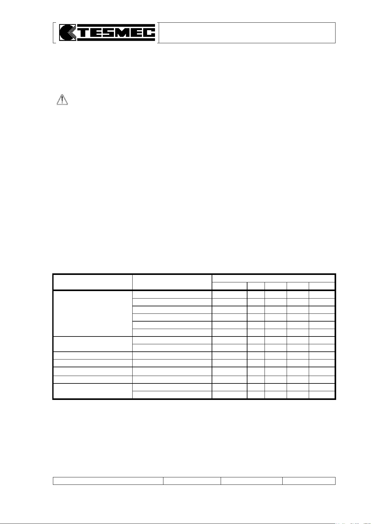
Part
Object
Interval
Daily
50 h
250 h
500 h
1500 h
Diesel engine (***)
Engine oil
CL
ST
Oil filter
ST
Cooling liquid
CL ST
Air filter
VF ST
Fuel
CL
Fuel filter
ST
Hydraulic circuit
Hydraulic oil
CL
ST1
ST(*)
Filters
VF
ST1
ST(*)
Negative brake
Discs
(**)
Reduction gear
Oil
CL
ST1
ST(*)
Bull-wheels
Gears
GR
Front plough
Rod
GR
Axle
Tyres pressure
VF
Stationary brake
GR
7.8 RADIATOR’S MAINTENANCE
At least once a year, or more in case of use in dusty places, is foreseen a blowhole with compressed
air of the radiant mass of the radiators.
7.9 GREASING
Grease 2-3 times per day the crown gear of the bull-wheels using the suitable greaser (table 2, pos. 2).
Weekly grease all the other parts subjected to rotation or translation and that not foreseen a forced
lubrication or an automatic greasing.
Use IP ATHESIA GR2 (ISO XBCEA 2) grease or equivalent of another trademark based on the
enclosed "SUGGESTED LUBRICANTS" table.
7.10 OTHER PERIODIC OPERATIONS
When cleaning the machine, avoid direct jets of water or steam on the components of the electric
system of the machine and on the control panel.
For the other periodic operations, refer to the summary table for the ordinary maintenance (see next
paragraph).
7.11 SUMMARY TABLE FOR ORDINARY MAINTENANCE
In this card are listed main operation of periodic maintenance and relevant intervals.
Legend:
CL Check the level (and possible filling up)
GR Grease
ST Replace
ST1 Replace (only for the first intervene)
VF Check
(*) Or in any case every year
(**) Check the discs wear condition after an emergency stop
(***) For further information see the engine booklet
Page 34

PULLER-TENSIONER
Model: AFS303
Manual: MI-AFS303-320-00-GB
Date: 30.03.2015
Author: MC
Page: 31 of 32
8. HOW TO DISABLE THE MACHINE
8.1 TRANSPORT
Before transporting the machine, empty any liquid that can be set on fire contained in the machine
(oils and fuels).
Transport must be effectuated as per the specifications described in chapter 3 (Transport and
positioning instructions).
8.2 EXTENDED SERVICE STOP
When foreseeing an extended service stop (two months at least) protect the external parts with
waterproof wax and empty the fuel tank.
During service stop, start the machine at least once every two months and let the machine idle for one
hour at least, so that the oil enters in the hydraulic system and to prevent the gaskets drying.
We recommend stocking the machine under a roof; do not cover the machine with pieces of cloth
and/or plastic materials that cause an excessive increase of the temperature and humidity.
If the machine does not work for a year or more, before re-starting the machine it is necessary to
replace the hydraulic oil and filters of the hydraulic circuit.
8.3 STRIPPING
Machine stripping has to be carried out by the manufacturer or by a specialised factory.
All the stripping operations have to be effectuated in conformity with the norms in force for accident
prevention.
Waste materials have to be divided for typology (i.e. iron scrap, aluminium, plastic, rub, etc.) and
disposed of by means of authorised structures in conformity with the laws in force.
Exhausted oils and polluting substances have to be disposed of by means of authorised structures in
conformity with the laws in force.
Page 35

PULLER-TENSIONER
Model: AFS303
Manual: MI-AFS303-320-00-GB
Date: 30.03.2015
Author: MC
Page: 32 of 32
9. ENCLOSED DOCUMENTS
9.1 TABLES
TABLE 1.3 Control panel
TABLE 2.1 General assembly – Lateral view
TABLE 3.1 General assembly – Upper view
TABLE 5.1 Hydraulic heads connection
TABLE 6.1 Compressor connection (optional)
Comparative table of suggested oils and greases
9.2 SYSTEMS
A10-00036 Frame assembly drawing
A12-00016 Reduction assembly drawing
A13-00005 Coverings assembly drawing
A14-00042 Feeding system assembly drawing
A15-00023 Control panel assembly drawing
A17-00029 Nylon roller assembly drawing
A25-00062 Engine covers assembly
S01-00013 Electric system
S02-00020 Functional hydraulic system
9.3 OTHER DOCUMENTS
Manual for engine use and maintenance mod. KOHLER KDW 2204
Page 36

Page 37

PULLER-TENSIONER MOD. AFS303
TABLES
- 24050 Grassobbio (Bg) via Zanica, 17/O - 24060 Endine Gaiano (Bg) via Pertegalli
Tel. 0039 / 035 / 4232911 Tel. 0039 / 035 / 825024
Telefax 0039 / 035 / 4522445 Telefax 0039 / 035 / 826375
E-mail: [email protected] E-mail: [email protected]
Page 38

PULLER
-
TENSIONER
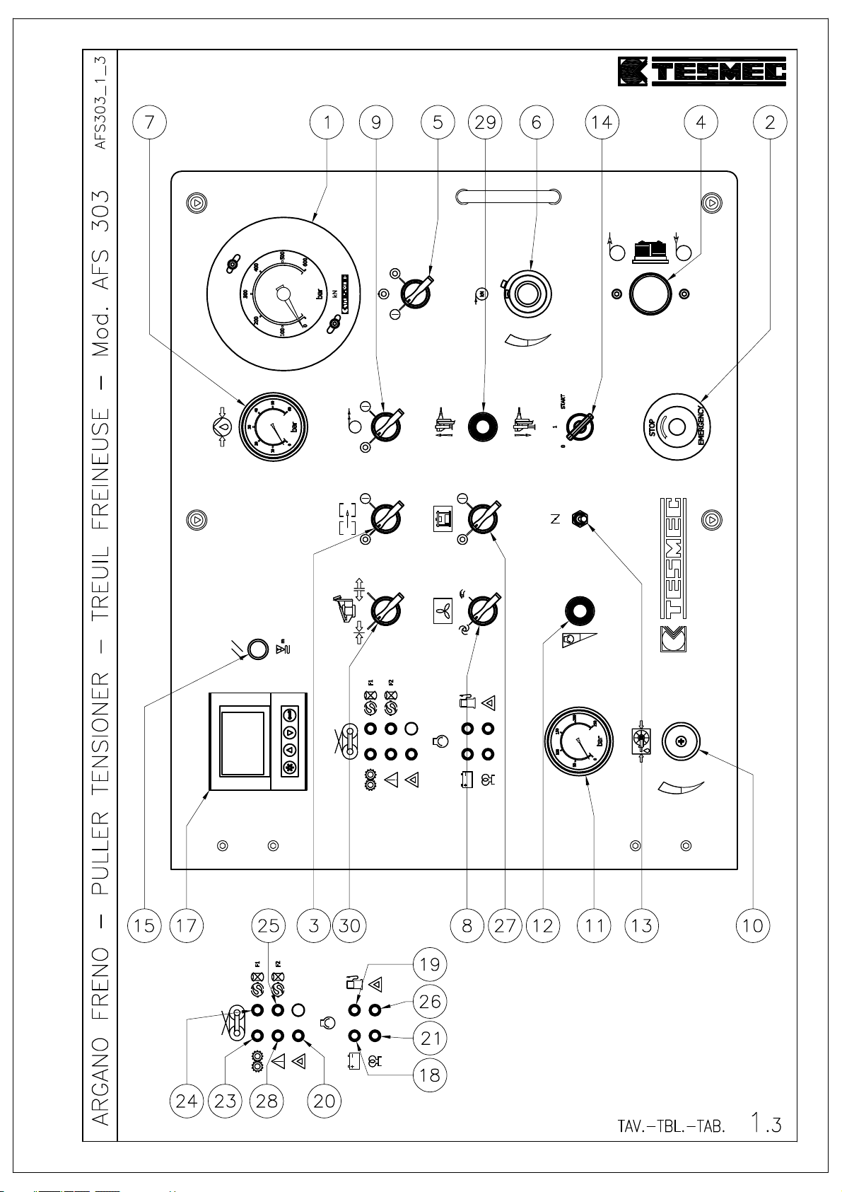
TABLE 1.3
1) Manometer with graduated ring nut.
2) Emergency stop push button.
3) Connected machines selector (optional)
4) Bull-wheels control lever.
5) Pull value setting device.
6) Pull value setting knob.
7) Manometer for overfeeding pressure.
8) Fan function selector.
9) Speed synchronizer selector (optional).
10) Adjusting valve for reel elevator/reel winder pressure.
11) Manometer for reel elevator/reel winder pressure.
12) Diesel engine accelerator.
13) IPO push button.
14) Diesel engine ignition key.
15) Meter-counter capstans reset push-button.
16)
17) Multi-functional display.
18) Generator lamp.
19) Fuel pilot lamp.
20) Pilot lamp for electric pull limiting device exceeding.
21) Pre-heating glow plugs lamp.
22)
23) Fine braking pilot lamp.
24) F1 filter pilot lamp.
25) F2 filter pilot lamp.
26) Engine ALARM pilot light
27) Selector for compressor connection (optional).
28) Alarm lamp card.
29) Lever for front plough movement.
30) Rope locking device selector (optional).
Model: AFS303
Page 39
Page 40

PULLER
-
TENSIONER
Model: AFS303
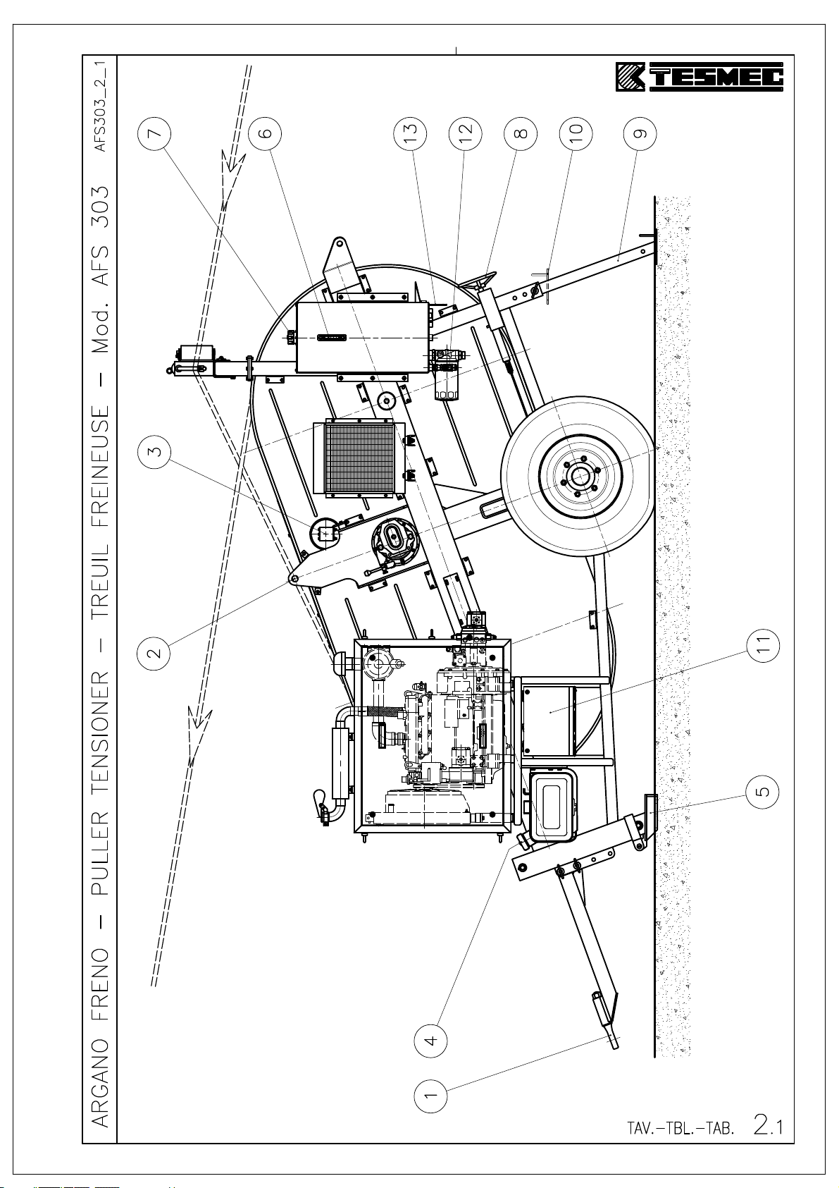
TABLE 2.1
1) Towing eye.
2) Lifting ear.
3) Encoder.
4) Fuel filling cap.
5) Front plough.
6) Hydraulic oil level indicator.
7) Hydraulic oil filling cap (IP HYDRUS OIL 46, qty 140 liters).
8) Hand-wheel for parking brake.
9) Rear stabilizer in working position.
10) Rear stabilizer in transport position.
11) Tools/battery box.
12) Hydraulic oil draining cock.
13) Rapid couplers (see table 5) (optional 010).
Page 41
Page 42

PULLER
-
TENSIONER
Model: AFS303
TABLE 3.1
1) Crown-pinion lubricator.
2) Anchoring ears.
3) Anchoring ears.
4) Hydraulic oil filter.
5) Hydraulic oil filter.
6) Oil filling cap for diesel engine.
7) Liquid filling cap for diesel engine radiator.
8) Lever for reduction gear speed change.
• pos. C: high pull (normal braking)
• pos. A: idle bull-wheels
• pos. B: low pull (fine braking).
9) Negative brake oil filling cap (IP HYDRUS OIL 46, qty 0.3 liters).
10) Negative brake oil draining plug.
11) Negative brake oil level.
12) Reduction gear oil filling cap (IP MELLANA-220, qty 1.6 liters).
13) Reduction gear oil draining plug.
14) Reduction gear oil level.
15) Control panel.
Page 43
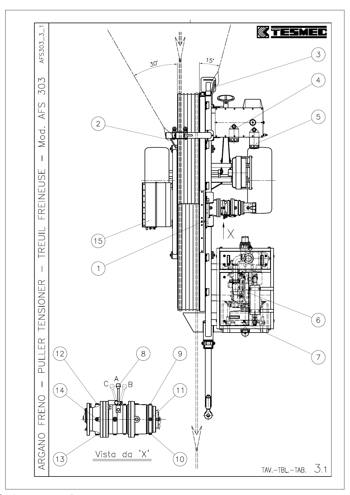
Page 44

PULLER
-
TENSIONER
1) Rapid coupler for high pressure.
2) Valve for reel rotation stop.
3) Rapid coupler for draining (eventual).
4) Rapid coupler for low pressure.
TABLE 5.1
Model: AFS303
Page 45
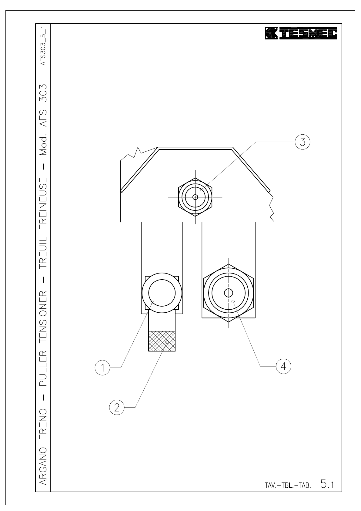
Page 46

PULLER
-
TENSIONER
Model: AFS303
TABLE 6.1 (OPTIONAL)
1) Pressure adjusting valve.
2) Manometer.
3) Valve block.
4) Opening/closing lever for compressor feeding (pos. A: compressor connection, pos. B:
compressor release).
5) Rapid coupler for high pressure.
6) Rapid coupler for low pressure.
Page 47
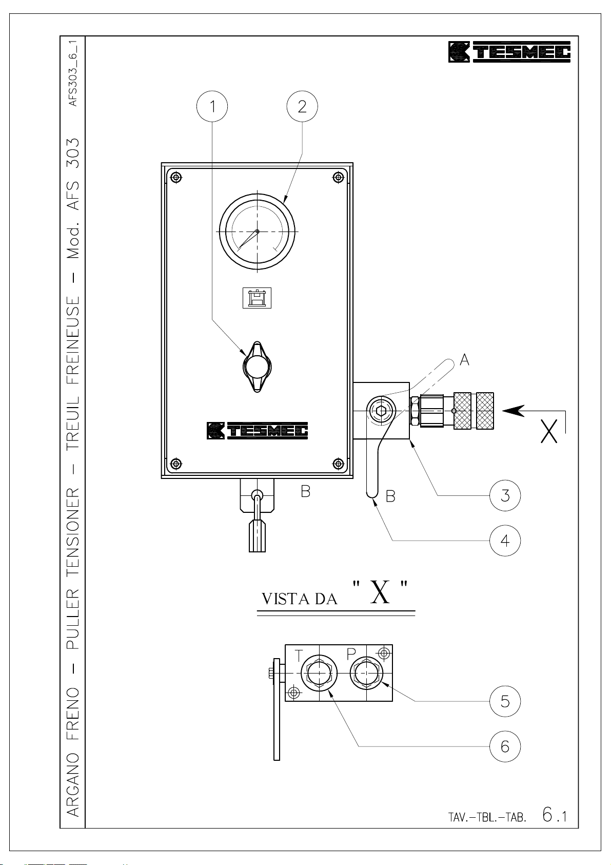
Page 48
Comparative table of suggested oils and grease
s
REDUCTION UNIT - COUPLERS
TYPE
ARTIC WINTER SUMMER TROPICAL ARTIC WINTER SUMMER TROPICAL
VISCOSITY
(ISO 3448)
AGIP OSO 22 OSO 32 OSO 46 OSO 68 BLASIA 100 BLASIA 150 BLASIA 220 BLASIA 320 GR MU EP 2
API APILUBE CIS 22 APILUBE CIS 32 APILUBE CIS 46 APILUBE CIS 68 DT 100 DT 150 DT 220 DT 320 PGX 2
ARAL ARAL VITAM GF 22 ARAL VITAM GF 32 ARAL VITAM GF 46 ARAL VITAM GF 68 DEGOL BG 100 DEGOL BG 150 DEGOL BG 220 DEGOL BG 320 ARALUB HL 2
AVIA AVILUB RSL 22 AVILUB RSL 32 AVILUB RSL 46 AVILUB RSL 68 AVILUB RSX 100 AVILUB RSX 150 AVILUB RSX 220 AVILUB RSX 320 -
BP ENERGOL HLP 22 ENERGOL HLP 32 ENERGOL HLP 46 ENERGOL HLP 68 ENERGOL GR-XP 100 ENERGOL GR-XP 150 ENERGOL GR-XP 220 ENERGOL GR-XP 320 GREASE LTX 2
CASTROL HYSPIN AWS 22 HYSPIN AWS 32 HYSPIN AWS 46 HYSPIN AWS 68 ALPHA SP 100 ALPHA SP 150 ALPHA SP 220 ALPHA SP 320 SUPERGREASE 2
CHEVRON EP HYDRAULIC 22 EP HYDRAULIC 32 EP HYDRAULIC 46 EP HYDRAULIC 68 COMPOUND GEAR 100 COMPOUND GEAR 150 COMPOUND GEAR 220 COMPOUND GEAR 320 DURALITH EP 2
ELF ELFOLNA DS 22 ELFOLNA DS 32 ELFOLNA DS 46 ELFOLNA DS 68 REDUCTELF SP 100 REDUCTELF SP 150 REDUCTELF SP 220 REDUCTELF SP 320 ROLEXA 2
ESSO NUTO H 22 NUTO H 32 NUTO H 46 NUTO H 68 SPARTAN EP 100 SPARTAN EP 150 SPARTAN EP 220 SPARTAN EP 320 BEACON 2
FINA HYDRAN 22 HYDRAN 32 HYDRAN 46 HYDRAN 68 GIRAN 100 GIRAN 150 GIRAN 220 GIRAN 320 MARSON EP L2
FUCHS RENOLIN MR 5 RENOLIN MR 10 RENOLIN MR 15 RENOLIN MR 20 - RENEP COMPOUND 104 - RENEP COMPOUND 108 -
GULF HARMONY 22 AW HARMONY 32 AW HARMONY 46 AW HARMONY 68 AW - EP LUBRICANT HD 150 EP LUBRICANT HD 220 EP LUBRICANT HD 320 CROWN EP 2
IP HYDRUS OIL 22 HYDRUS OIL 32 HYDRUS OIL 46 HYDRUS OIL 68 MELLANA 100 MELLANA 150 MELLANA 220 MELLANA 320 ATHESIA EP GR 2
KLUBER LAMORA 22 LAMORA 32 LAMORA 46 LAMORA 68 LAMORA 100 LAMORA 150 LAMORA 220 LAMORA 320 CENTOPLEX 2 EP
MOBIL DTE 22 DTE 24 DTE 25 DTE 26 - MOBILGEAR 629 MOBILGEAR 630 MOBILGEAR 632 MOBILUX EP 2
Q8 HAYDIN 22 HAYDIN 32 HAYDIN 46 HAYDIN 68 GOYA 100 GOYA 150 GOYA 220 GOYA 320 REMBRANDT EP 2
ROLOIL LI 22 LI 32 LI 46 LI 68 EP 100 EP 150 EP 220 EP 320 LITEX EP 2
SHELL TELLUS 22 TELLUS 32 TELLUS 46 TELLUS 68 OMALA 100 OMALA 150 OMALA 220 OMALA 320 SUPERGREASE EP2
SYNECO - PACEMAKER 32 PACEMAKER 46 PACEMAKER 68 - PACEMAKER RODI 12 - PACEMAKER RODI 24 SINT GREASE EP 2
TAMOIL HYDRAULIC OIL 22 HYDRAULIC OIL 32 HYDRAULIC OIL 46 HYDRAULIC OIL 68 CARTER EP 100 CARTER EP 150 CARTER EP 220 CARTER EP 320 TAMLITH GREASE EP2
TEXACO RANDO HD 22 RANDO HD 32 RANDO HD 46 RANDO HD 68 MEROPA 100 MEROPA 150 MEROPA 220 MEROPA 320 MULTIFAK EP 2
TOTAL AZOLLA ZS 22 AZOLLA ZS 32 AZOLLA ZS 46 AZOLLA ZS 68 CARTER EP 100 CARTE EP 150 CARTER EP 220 CARTER EP 320 MULTIS EP 2
VALVOLINE ELIOS HVI 22 ELIOS HVI 32 ELIOS HVI 46 ELIOS HVI 58 ELIOS EP 100 ELIOS EP 150 ELIOS EP 220 ELIOS EP 320 LITHIUM BASE EP 2
VG 22 VG 32 VG 46 VG 68 VG 100 VG 150 VG 220 VG 320 NLGI 2
REDUCTION UNIT OIL FOR ENVIROMENTAL CONDITION:HYDRAULIC CIRCUIT OIL FOR ENVIROMENTAL CONDITION:
GREASING
GREASE FOR EACH
AMBIENT
Tavole Oli - 16/09/2004 - Pagina 1 di 1 - GB
Page 49

PULLER-TENSIONER MOD. AFS303
ENCLOSED DOCUMENTS
- 24050 Grassobbio (Bg) via Zanica, 17/O - 24060 Endine Gaiano (Bg) via Pertegalli
Tel. 0039 / 035 / 4232911 Tel. 0039 / 035 / 825024
Telefax 0039 / 035 / 4522445 Telefax 0039 / 035 / 826375
E-mail: [email protected] E-mail: [email protected]
Page 50

IMPORTANTE
Per qualsiasi informazione riguardante questa macchina/attrezzatura (utilizzo, manutenzione, ricambi) citare sempre Modello, Numero di
matricola, Commessa, Anno di fabbricazione rilevabile nella targa d'identificazione della macchina.
Questo manuale non descrive le procedure di tesatura, né si è cercato di dare istruzioni all’utilizzatore sui metodi di tesatura.
Il contenuto di questo manuale prevede unicamente un testo di base per l’uso, manutenzione e l’elenco dei pezzi di ricambio della macchina
stessa e come s'intende e si suggerisce di utilizzarla. Saranno graditi suggerimenti da parte degli Utilizzatori per migliorare questa pubblicazione.
Scriveteci all’indirizzo sottoindicato.
IMPORTANT NOTE
State always “Model, Serial Number and Manufacturing Year” of the machine/equipment in case you need information on use, maintenance and
spare parts. The a/m data can be found on the identification plate of the machine itself.
This is not a stringing procedures manual, and no attempt is made or implied herein to instruct the user in stringing methods.
The contents of this manual are intended as base line for operation, maintenance and part list of the unit as it stands alone and as it is intended
and anticipated to be used. Recommendation by the individual user for improving this publication is encouraged and should be forwarded to the
address on this page.
IMPORTANT
Indiquer toujours le modèle, le numéro de série et l’année de fabrication de la machine/équipement même, en demandant à TESMEC
renseignements sur l’utilisation, l’entretien et les pièces de rechange. Ces informations se trouvent sur la plaque d'identification de la machine.
Ce manuel ne décrit pas les procédures de déroulage, ni on a tache de donner instructions à l'Utilisateur sur les méthodes de déroulage.
Le contenu de ce manuel prévoit seulement un texte pour l’utilisation, l’entretien et la liste de pièces de rechange et comme TESMEC conseille
d’utiliser la machine même. Pour chaque suggestion pour améliorer cette machine, écrire à l’adresse au-dessous.
IMPORTANTE
Para cualquier información relativa a esta máquina/equipo (utilización, mantenimiento, repuestos) citar siempre Modelo, Número de serie, Orden
de compra, Año de fabricación que se hallan en la tarjeta de identificación de la máquina.
Este manual no describe los procedimientos de tensado y tampoco se ha tratado de dar instrucciones al utilizador acerca de los métodos de
tensado. El contenido de este manual prevé únicamente un texto básico para el uso, mantenimiento y el listado de repuestos de la misma
máquina y cómo se pretende y se sugiere utilizarla. Se apreciarán sugerencias por parte de los utilizadores para mejorar esta publicación.
Nos pueden escribir a la dirección indicada abajo.
IMPORTANTE
Para qualquer informação a respeito desta máquina/equipamento (utilização, manutenção, peças sobresselentes) citar sempre o Modelo, o
Número de Série, a Encomenda, o Ano de fabrico,dados que podem ser encontrados na placa de identificação da máquina.
Este manual não descreve os procedimentos de entesadura, tão pouco foi nossa intenção dar instruções ao utilizador sobre os métodos de
entesadura. O conteúdo deste manual de instruções prevê unicamente um texto básico para o uso, a manutenção e a lista das peças
sobresselentes da mesma máquina e como se entende e se sugere utilizá-la.
Serão muito bem aceitas sugestões por parte dos Utilizadores, no intento de melhorar esta publicação.
Escrevam-nos no endereço abaixo indicado.
WICHTIG
Geben Sie für alle Informationen über diese Maschine/Ausrüstung (Verwendung, Wartung, Ersatzteile) immer Modell, Matrikelnummer,
Bestellung und Baujahr an, was Sie dem Identifizierungsschild der Maschine entnehmen können.
Dieses Handbuch beschreibt nicht die Verfahren des Spannens, und es wurde auch nicht versucht, dem Verwender Anleitungen über die
Methoden des Spannens zu geben. Der Inhalt dieses Handbuchs enthält allein einen Basistext für den Gebrauch und die Wartung, die
Ersatzteilliste der Maschine und außerdem, welche Verwendung für sie bezweckt und empfohlen wird.
Wir freuen uns über Tipps von Seiten der Verwender, um diese Veröffentlichung zu verbessern.
Schreiben Sie uns an unten angegebene Adresse.
ВАЖНОЕ ПРИМЕЧАНИЕ
Всегда следует указывать «модель, серийный номер и год выпуска» машины/оборудования в случае, если вам необходима
информация по эксплуатации, техническому обслуживанию и запасным частям. Вышеупомянутые данные можно найти на
паспортной табличке на самой машине.
Руководство по эксплуатации не является руководством по методикам натяжения, и в нем не делается никаких попыток
инструктирования пользователя способам натяжения, и они не подразумеваются.
Цель настоящего руководства состоит только в том, чтобы дать описание эксплуатации и технического обслуживания, а также список
запасных частей машины, и указать ее назначение и рекомендуемое использование. Рекомендации отдельных пользователей по
улучшению данной публикации приветствуются, и их следует направлять по адресу, указанному в руководстве.
- 24050 Grassobbio (Bg) via Zanica, 17/O - 24060 Endine Gaiano (Bg) via Pertegalli
Tel. 0039 / 035 / 4232911 Tel. 0039 / 035 / 825024
Telefax 0039 / 035 / 4522445 Telefax 0039 / 035 / 826375
E-mail: [email protected] E-mail: [email protected]
Page 51
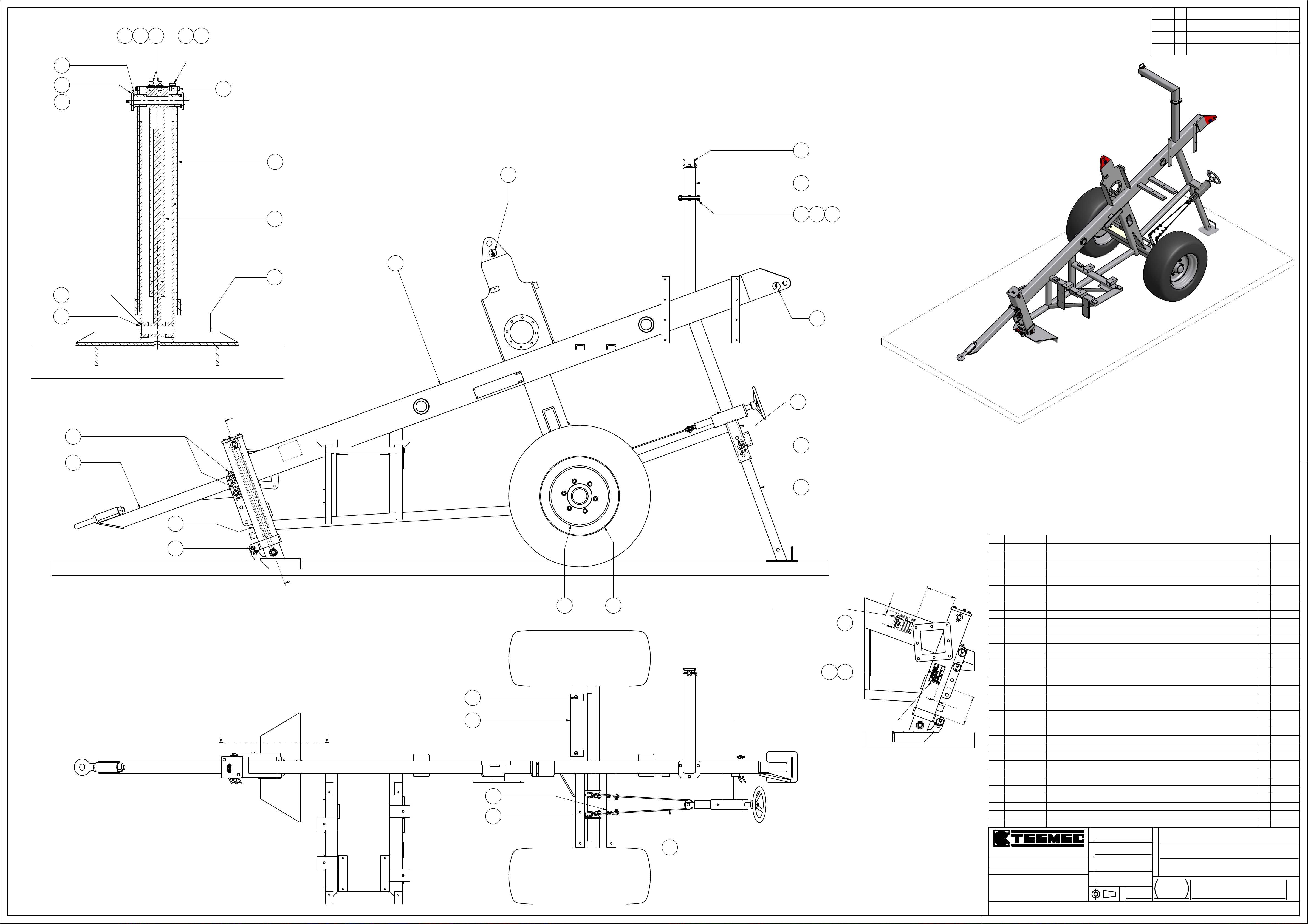
DATE
SYM
REVISION RECORD
CKDR
.
10911
14 13
.
.
7
8
6
12
15
1
32
21
3
22 23 24
1
2
5
4
33
Sezione "B-B"
15
16
( 1 : 5 )
34
B
15
20
34
17
B
A A
26
25
29
28
18 19
27
2
D99-90000 - Targa Datti
30
3130
RIDUTTORE - OLIO : ISO VG 220 - LITRI : 1.1
CIRCUITO IDRAULICO - OLIO : ISO VG 46 - LITRI : 150
1
9
5
0
4
Sezione "A-A"
( 1 : 10 )
V00-9800-02434
V00-9800-00733
ADESIVO T. 60 MESSA A TERRA GENERALE [] STICKER
ADESIVO D. 50 PUNTO DI STROPPAGGIO [] STICKER
ADESIVO D. 50 PUNTO DI SOLLEVAMENTO MACCHINA [] STICKERV00-9800-00632
D99-9014931
TARGA OLIO CIRCUITO IDRAULICO / RIDUTTORE 1.5 x 70 x 120 [] PLATE
2
1
1
1
0 kg
0 kg
0 kg
0 kg
0 kg8RIVETTO UNI 9200 - A D. 3.2 x 9 - P-AlMg 2.5 [] RIVETV00-9050-00330
V00-9000-01429
V00-9000-01528
V00-9000-02927
MORSETTO A CAVALLOTTO D. 5-6 - AMA : Art.564 [] CLAMP
REDANCIA PER FUNE - DIN 6899B X FUNE D. 7 [] THIMBLE
FUNE ACCIAIO ZINCATO 114 FILI - D. 6 mm CR= 21.92 kN [] CABLE
6
2
1
0 kg
0 kg
0.4 kg
0 kg2VITE - ISO 10642 - M 10 x 25 - 10.9 - TSEI - PG [] BOLTH58-0010-02526
D00-0031625
H77-1008-01124
H81-1008-00223
PROTEZIONE ASSALE 15 x 80 x 400 [] GUARD
DADO - UNI 7473 - M 8 - GR. 8 - Z - AUTOB. [] LOCKNUT
ROSETTA - ISO 7089 - TE - 8 - 100 HV - Z [] WASHER
1
0.5 kg
3
6
0 kg
0 kg
0 kg3VITE - M 8 x 30 - ISO 4017 - 8.8 - Z [] BOLTH50-1008-03022
D00-0031121
D00-0180420
V00-2130-00119
SUPPORTO RULLI 140 x 500 x 705 [] SUPPORT
STABILIZZATORE POSTERIORE - Tubo Quadro 60 - I=20° 200 x 200 x 965 [] STABILIZER
PNEUMATICO - 30 Km/h - 13.0/65-18 PR:16 - PORTATA: 3330 Kg - 5.00 bar [] TYRE + AIR TUBE
1
17.4 kg
1
12.3 kg
2
33.4 kg
30.4 kg2CERCHIONE - N° 6 Fori - 30 Km/h - 11.00x18 - SPOSTAMENTO: 0 - INTERGOMMA [] TIRE RIMV00-2160-00118
V00-9020-01017
16
V00-9020-00115
0
0
9
1
14
13
H88-1010-002
PERNO x TERZO PUNTO - AMA : Art.178 D. 19 x lg. 120 - CATENELLA E SPINA A SCATTO [] PIN
TIMONE 80 x 138 x 1071 [] RUDDERD00-00310
SPINOTTO - AMA : Art.1 D. 19 x lg. 110 - CON CATENELLA E SPINA A SCATTO [] PIN
ROSETTA - UNI 1751 - A - 10 - Z [] WASHER
COPERCHIO VOMERE 15 x 140 x 140 [] COVERD00-0180512
D99-1001711
D99-1000610
F11-0003-0039
GRANO FORATO - 8x12 - FORO ø1 [] DOWL
NIPPLO FORATO - 1/4" Gas - FORO M8 [] NIPPLE
RONDELLA RAME D. 1/4" x 3 [] WASHER
1
0.4 kg
1
19.8 kg
4
0.4 kg
0 kg2VITE - ISO 4017 - M 10 x 10 - 8.8 - Z - TE - PG - I.FIL [] BOLTH50-1010-010
2
1
2
2
2
0 kg
0.4 kg
0 kg
0 kg
0 kg
0 kg2COPIGLIA - ISO 1234 D. 6.3 x 40 - St [] COTTER PINV00-9030-0218
H81-1024-0047
D00-003136
5
V00-9010-013
4
V00-6500-0613
D00-003122
1
D00-01835
ROSETTA - ISO 7089 - TE - 24 100 HV - Z [] WASHER
PERNO D. 25 x lg. 177 - FORO COPIGLIE [] PIN
ANELLO - UNI 7435 - 25 - E (SEEGER) [] RING
PERNO D. 25 x lg. 108 - SEDE SEEGER [] PIND00-00314
CILINDRO A: 40 S: 25 - C: 500 - CHIUSO: 700 - APERTO: 1200 - CON VALVOLA [] CILYNDER
STABILIZZATORE ANTERIORE 290 x 700 x 907 [] STABILIZER
TELAIO COMPLETAMENTO - AFS 303 310 [] FRAME
ITEM
O
O
O
O
T
T
T
T
S
S
S
S
I
I
I
I
V
V
V
V
.
.
.
.
S
S
S
S
I
I
I
GGGGRRRRAAAASSSSSSSSOOOOBBBBBBBBIIIIOOOO ((((BBBBGGGG)))) TTTTeeeellll....000033335555////4444222233332222999911111111 ---- FFFFaaaaxxxx 000033335555////4444555522222222444444445555
EEEENNNNDDDDIIIINNNNEEEE GGGG ((((BBBBGGGG)))) TTTTeeeellll....000033335555////888822225555000022224444 ---- FFFFaaaaxxxx 000033335555////888822226666333377775555
TTTTUUUUTTTTTTTTEEEE LLLLEEEE NNNNOOOORRRRMMMMEEEE RRRRIIIICCCCHHHHIIIIAAAAMMMMAAAATTTTEEEE SSSSIIII IIIINNNNTTTTEEEENNNNDDDDOOOONNNNOOOO
NNNNEEEELLLLLLLLAAAA LLLLOOOORRRROOOO UUUULLLLTTTTIIIIMMMMAAAA EEEEDDDDIIIIZZZZIIIIOOOONNNNEEEE....
SSSSAAAALLLLDDDDAAAATTTTUUUURRRREEEE IIIINNNN AAAACCCCCCCCOOOORRRRDDDDOOOO CCCCOOOONNNN ---- WWWWPPPPSSSS 1111÷÷÷÷9999
GGGGRRRRAAAADDDDOOOO DDDDIIII PPPPRRRREEEECCCCIIIISSSSIIIIOOOONNNNEEEE PPPPEEEERRRR QQQQUUUUOOOOTTTTEEEE LLLLIIIINNNNEEEEAAAARRRRIIII,,,,
AAAANNNNGGGGOOOOLLLLAAAARRRRIIII,,,, GGGGEEEEOOOOMMMMEEEETTTTRRRRIIIICCCCHHHHEEEE NNNNOOOONNNN TTTTOOOOLLLLLLLLEEEERRRRAAAATTTTEEEE
LLLLAAAAVVVV....MMMMEEEECCCCCCCCAAAANNNNIIIICCCCHHHHEEEE
CCCCAAAARRRRPPPPEEEENNNNTTTTEEEERRRRIIIIAAAA
IIIIllll ddddiiiisssseeeeggggnnnnoooo èèèè pppprrrroooopppprrrriiiieeeettttàààà ddddeeeellllllllaaaa TTTTEEEESSSSMMMMEEEECCCC ssss....pppp....aaaa.... AAAA tttteeeerrrrmmmmiiiinnnniiii ddddiiii lllleeeeggggggggeeee ssssiiii vvvviiiieeeettttaaaa ttttaaaassssssssaaaattttiiiivvvvaaaammmmeeeennnntttteeee llllaaaa rrrriiiipppprrrroooodddduuuuzzzziiiioooonnnneeee eeee llllaaaa ddddiiiivvvvuuuullllggggaaaazzzziiiioooonnnneeee aaaa tttteeeerrrrzzzziiii....
UUUUNNNNIIII EEEENNNN 22222222777766668888----ffff HHHH
UUUUNNNNIIII EEEENNNN 22222222777766668888----cccc KKKK
I
D
D
D
D
A
A
A
A
T
T
T
T
A
A
A
A
23/09/2011
D
D
D
D
O
O
O
O
S
S
S
S
E
E
E
E
P
P
P
P
Foresti P.
653,77 kg
A
A
A
A
L
L
L
L
A
A
A
A
1:10
C
C
C
C
S
S
S
S
E
E
E
E
N
N
N
N
O
O
O
O
ARGANO FRENO SINGOLO
I
I
I
I
Z
Z
Z
Z
A
A
A
A
N
N
N
N
I
I
I
I
M
M
M
M
AFS 303 310 - PULL 25 kN
O
O
O
O
N
N
N
N
E
E
E
E
D
D
D
D
ASSIEME MONTAGGIO TELAIO
FFFFOOOOGGGGLLLLIIIIOOOO
1 / 1
NNNNUUUUMMMMEEEERRRROOOO DDDDIIIISSSSEEEEGGGGNNNNOOOO
A10-00036
2
1
2
1
1
1
1
0 kg
0.7 kg
0 kg
0.4 kg
9 kg
33.8 kg
428.6 kg
WEIGHTQTYDESCRIPTIONCODE
A1
Page 52
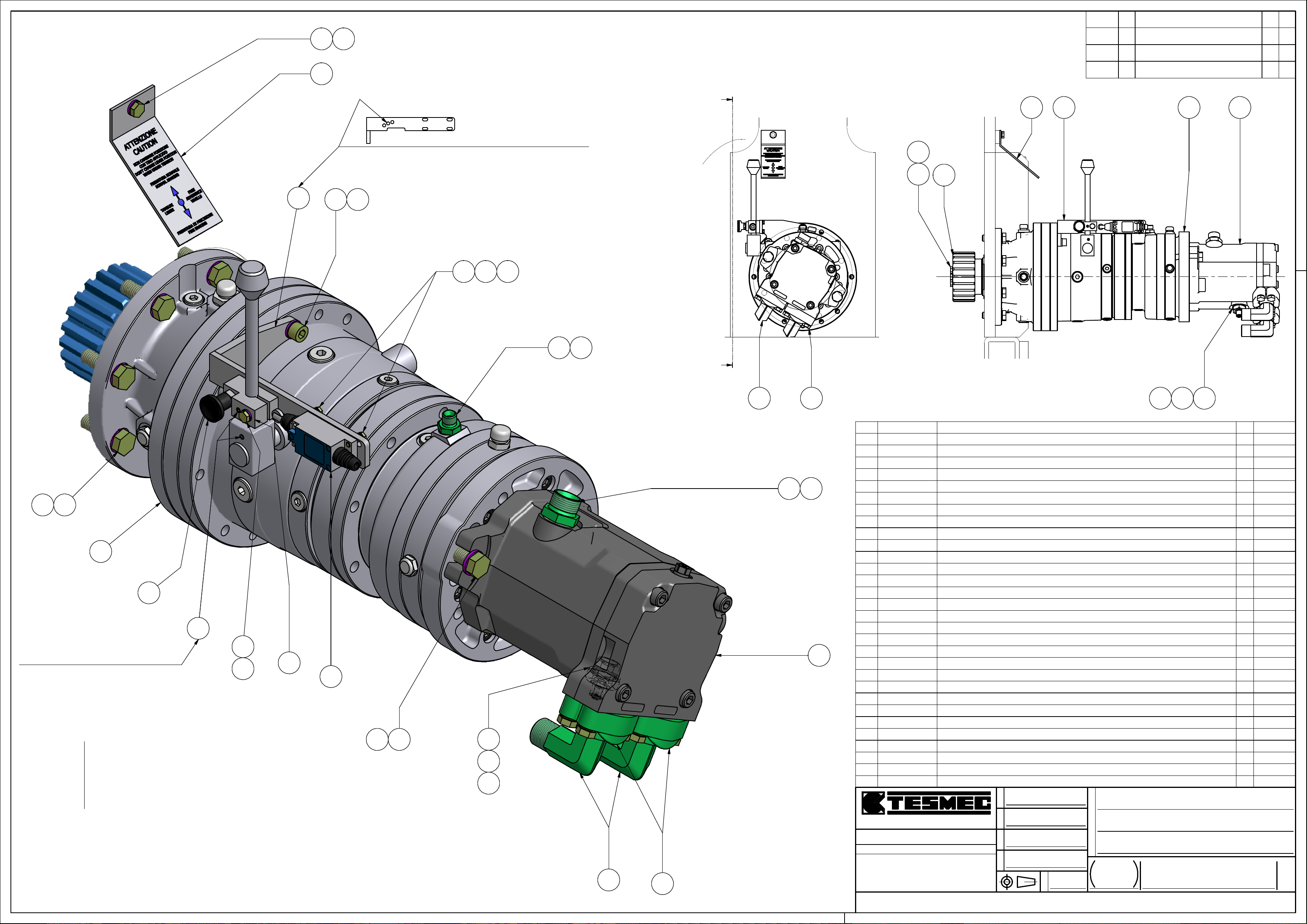
DATE
SYM
REVISION RECORD
CKDR
3
15 24
7
19 25
Eseguire fori ø7 a montaggio
per posizionamento leva
A
24
16
.
.
.
3
4
287 27
1826
27
30
Eseguire fori M5 per grani a montaggio
20
14
23
13 21 22
9 12
Sezione "A-A"
A
8
1
5
OTTURATORE PISTONCINO A MOLLA - ELESA : GN 617-6-A-NI [] SHUTTERV00-9040-02730
10
11
V00-8510-03629
V00-6050-02428
V00-5702-02427
H88-1014-00326
H88-1010-00225
FINECORSA A PULSANTE CON ROTELLA - 1 N.A + 1 N.C - 5A-250 VAC [] LIMIT SWITCH
MOTORE IDRAULICO 50CC - LINDE HMF 50 - 02 [] MOTOR
RIDUTTORE RR 510 MS - R: 7 + CAMBIO - RFF 5/43 - SAE 'C' - FF. 12001 [] GEARBOX
ROSETTA - UNI 1751 - A - 14 - Z [] WASHER
ROSETTA - UNI 1751 - A - 10 - Z [] WASHER
ROSETTA - UNI 1751 - A - 8 - Z [] WASHERH88-1008-00224
23
ROSETTA - UNI 1751 - A - 6 - Z [] WASHERH88-1006-002
ROSETTA - UNI 1751 - A - 5 - Z [] WASHERH88-1005-00122
H81-1005-00121
H61-0005-01220
H56-1010-06019
H50-1014-04017
H50-1008-02516
H50-1008-01215
14
H50-1006-030
ROSETTA - ISO 7089 - TE - 5 - 100 HV - Z [] WASHER
VITE - UNI 5927 - M 5 x 12 45H (12.9) - GRANO ESTEMITÀ CONICA [] BOLT
VITE - M 10 x 60 - ISO 4762 - 8.8 - Z [] BOLT
VITE - M 14 x 40 - ISO 4017 - 8.8 - Z [] BOLT
VITE - M 8 x 25 - ISO 4017 - 8.8 - Z [] BOLT
VITE - M 8 x 12 - ISO 4017 - 8.8 - Z [] BOLT
VITE - ISO 4017 - M 6 x 30 - 8.8 - Z - TE - PG - I.FIL [] BOLT
VITE - ISO 4017 - M 5 x 16 - 8.8 - Z - TE - PG - I.FIL [] BOLTH50-1005-01613
RONDELLA RAME D. 1/4" x 3 [] WASHERF11-0003-00312
2
28
29
F11-0001-02311
F04-0006-02210
F04-0001-0039
F02-0049-0088
7
D99-100576
5
D99-10034
26
17
11
D00-018134
RONDELLA - BONDED - M 22 Sp. 2 [] WASHER
NIPPLO 3/4 '' GAS - M22x1.5 [] NIPPLE
NIPPLO - 1/4" GAS - 1/4" GAS [] NIPPLE
RIDUZIONE 90° - 3/4" SAE 6000 FL - 3/4" GAS [] FITTING
TARGA CAMBIO RIDUTTORE 3 x 55 x 150 [] PLATED99-90180
NIPPLO FORATO - M 1/4" Gas - M22x1.5 - FORO M8 [] NIPPLE
GRANO FORATO - M 8x12 - FORO ø1.5 [] DOWL
PIGNONE D. 112.5 x 67 - Z= 21 - M= 5/3.75 [] SPROKET
STAFFA CAMBIO RIDUTTORE 59 x 107.5 x 200 [] MOUNTINGD00-003283
6
BLOCCHETTO CAMBIO RIDUTTORE 20 x 30 x 50 [] MANIFOLDD00-003272
A99-100611
5
GGGGRRRRAAAASSSSSSSSOOOOBBBBBBBBIIIIOOOO ((((BBBBGGGG)))) TTTTeeeellll....000033335555////4444222233332222999911111111 ---- FFFFaaaaxxxx 000033335555////4444555522222222444444445555
EEEENNNNDDDDIIIINNNNEEEE GGGG ((((BBBBGGGG)))) TTTTeeeellll....000033335555////888822225555000022224444 ---- FFFFaaaaxxxx 000033335555////888822226666333377775555
TTTTUUUUTTTTTTTTEEEE LLLLEEEE NNNNOOOORRRRMMMMEEEE RRRRIIIICCCCHHHHIIIIAAAAMMMMAAAATTTTEEEE SSSSIIII IIIINNNNTTTTEEEENNNNDDDDOOOONNNNOOOO
NNNNEEEELLLLLLLLAAAA LLLLOOOORRRROOOO UUUULLLLTTTTIIIIMMMMAAAA EEEEDDDDIIIIZZZZIIIIOOOONNNNEEEE....
SSSSAAAALLLLDDDDAAAATTTTUUUURRRREEEE IIIINNNN AAAACCCCCCCCOOOORRRRDDDDOOOO CCCCOOOONNNN ---- WWWWPPPPSSSS 1111÷÷÷÷9999
GGGGRRRRAAAADDDDOOOO DDDDIIII PPPPRRRREEEECCCCIIIISSSSIIIIOOOONNNNEEEE PPPPEEEERRRR QQQQUUUUOOOOTTTTEEEE LLLLIIIINNNNEEEEAAAARRRRIIII,,,,
AAAANNNNGGGGOOOOLLLLAAAARRRRIIII,,,, GGGGEEEEOOOOMMMMEEEETTTTRRRRIIIICCCCHHHHEEEE NNNNOOOONNNN TTTTOOOOLLLLLLLLEEEERRRRAAAATTTTEEEE
8
1
LLLLAAAAVVVV....MMMMEEEECCCCCCCCAAAANNNNIIIICCCCHHHHEEEE
CCCCAAAARRRRPPPPEEEENNNNTTTTEEEERRRRIIIIAAAA
IIIIllll ddddiiiisssseeeeggggnnnnoooo èèèè pppprrrroooopppprrrriiiieeeettttàààà ddddeeeellllllllaaaa TTTTEEEESSSSMMMMEEEECCCC ssss....pppp....aaaa.... AAAA tttteeeerrrrmmmmiiiinnnniiii ddddiiii lllleeeeggggggggeeee ssssiiii vvvviiiieeeettttaaaa ttttaaaassssssssaaaattttiiiivvvvaaaammmmeeeennnntttteeee llllaaaa rrrriiiipppprrrroooodddduuuuzzzziiiioooonnnneeee eeee llllaaaa ddddiiiivvvvuuuullllggggaaaazzzziiiioooonnnneeee aaaa tttteeeerrrrzzzziiii....
UUUUNNNNIIII EEEENNNN 22222222777766668888----ffff HHHH
UUUUNNNNIIII EEEENNNN 22222222777766668888----cccc KKKK
O
O
O
O
T
T
T
T
S
S
S
S
I
I
I
I
V
V
V
V
.
.
.
.
S
S
S
S
I
I
I
I
Foresti P.
D
D
D
D
A
A
A
A
T
T
T
T
A
A
A
A
28/09/2011
D
D
D
D
O
O
O
O
S
S
S
S
93,69 kg
E
E
E
E
P
P
P
P
A
A
A
A
L
L
L
L
A
A
A
A
C
C
C
C
S
S
S
S
1:2.5
E
E
E
E
N
N
N
N
O
O
O
O
ARGANO FRENO SINGOLO
I
I
I
I
Z
Z
Z
Z
A
A
A
A
N
N
N
N
I
I
I
I
M
M
M
M
AFS 303 310 - PULL 25 kN
O
O
O
O
N
N
N
N
E
E
E
E
D
D
D
D
ASSIEME MONTAGGIO RIDUTTORE
FFFFOOOOGGGGLLLLIIIIOOOO
1 / 1
NNNNUUUUMMMMEEEERRRROOOO DDDDIIIISSSSEEEEGGGGNNNNOOOO
A12-00016
11
6
1
1
1
1
10
2
5
1
4
4
2
2
0 kg
0.1 kg
3.3 kg
84 kg
0 kg
0 kg
0 kg
0 kg
0 kg
0 kg
0 kg
0.1 kg
0.1 kg8VITE - M 14 x 45 - ISO 4017 - 8.8 - Z [] BOLTH50-1014-04518
2
0.1 kg
4
1
1
4
1
2
1
1
2
1
1
1
1
1
1
0 kg
0 kg
0 kg
0 kg
0 kg
0 kg
0.1 kg
0 kg
0.4 kg
0.1 kg
0 kg
0 kg
2.6 kg
0.5 kg
0.2 kg
0.5 kg2ASSIEME SEMIFLANGIE SAE 6000 3/4" [] ASSEMBLY
WEIGHTQTYDESCRIPTIONCODEITEM
A2
Page 53
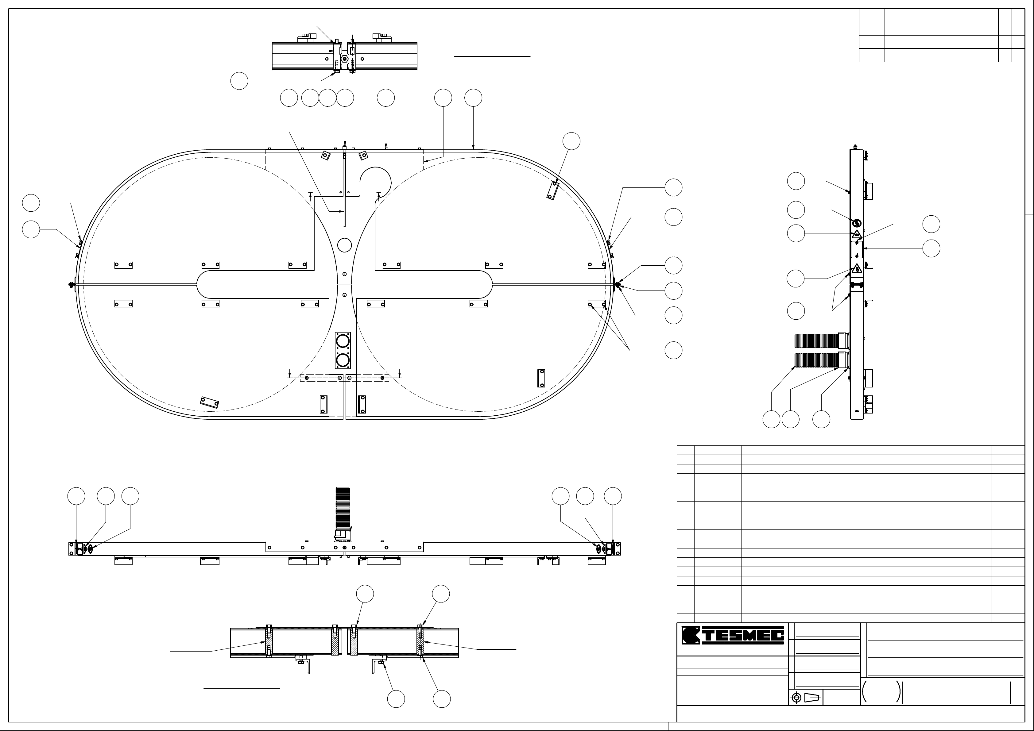
CODE D98-00076
10
CODE H88-1008-002
Sezione "B-B"
( 1 : 5 )
DATE
SYM
REVISION RECORD
CKDR
.
.
.
12
1
62
155
B B
10
4
3
10
10
12
18
1
12
16
1
11
17
16 18
D98-00075
Sezione "A-A"
( 1 : 5 )
A A
10
10
1010
D98-00075
18 16
17
8
7
10
V00-9800-01117
V00-9800-00816
V00-5303-00715
14
V00-2231-059
H99-8900-00611
H99-8900-00410
H99-8900-0029
H81-1008-0028
7
F99-0001-0016
5
F11-0003-003
D00-018174
D00-000971
GGGGRRRRAAAASSSSSSSSOOOOBBBBBBBBIIIIOOOO ((((BBBBGGGG)))) TTTTeeeellll....000033335555////4444222233332222999911111111 ---- FFFFaaaaxxxx 000033335555////4444555522222222444444445555
EEEENNNNDDDDIIIINNNNEEEE GGGG ((((BBBBGGGG)))) TTTTeeeellll....000033335555////888822225555000022224444 ---- FFFFaaaaxxxx 000033335555////888822226666333377775555
TTTTUUUUTTTTTTTTEEEE LLLLEEEE NNNNOOOORRRRMMMMEEEE RRRRIIIICCCCHHHHIIIIAAAAMMMMAAAATTTTEEEE SSSSIIII IIIINNNNTTTTEEEENNNNDDDDOOOONNNNOOOO
NNNNEEEELLLLLLLLAAAA LLLLOOOORRRROOOO UUUULLLLTTTTIIIIMMMMAAAA EEEEDDDDIIIIZZZZIIIIOOOONNNNEEEE....
SSSSAAAALLLLDDDDAAAATTTTUUUURRRREEEE IIIINNNN AAAACCCCCCCCOOOORRRRDDDDOOOO CCCCOOOONNNN ---- WWWWPPPPSSSS 1111÷÷÷÷9999
GGGGRRRRAAAADDDDOOOO DDDDIIII PPPPRRRREEEECCCCIIIISSSSIIIIOOOONNNNEEEE PPPPEEEERRRR QQQQUUUUOOOOTTTTEEEE LLLLIIIINNNNEEEEAAAARRRRIIII,,,,
AAAANNNNGGGGOOOOLLLLAAAARRRRIIII,,,, GGGGEEEEOOOOMMMMEEEETTTTRRRRIIIICCCCHHHHEEEE NNNNOOOONNNN TTTTOOOOLLLLLLLLEEEERRRRAAAATTTTEEEE
LLLLAAAAVVVV....MMMMEEEECCCCCCCCAAAANNNNIIIICCCCHHHHEEEE
CCCCAAAARRRRPPPPEEEENNNNTTTTEEEERRRRIIIIAAAA
IIIIllll ddddiiiisssseeeeggggnnnnoooo èèèè pppprrrroooopppprrrriiiieeeettttàààà ddddeeeellllllllaaaa TTTTEEEESSSSMMMMEEEECCCC ssss....pppp....aaaa.... AAAA tttteeeerrrrmmmmiiiinnnniiii ddddiiii lllleeeeggggggggeeee ssssiiii vvvviiiieeeettttaaaa ttttaaaassssssssaaaattttiiiivvvvaaaammmmeeeennnntttteeee llllaaaa rrrriiiipppprrrroooodddduuuuzzzziiiioooonnnneeee eeee llllaaaa ddddiiiivvvvuuuullllggggaaaazzzziiiioooonnnneeee aaaa tttteeeerrrrzzzziiii....
UUUUNNNNIIII EEEENNNN 22222222777766668888----ffff HHHH
UUUUNNNNIIII EEEENNNN 22222222777766668888----cccc KKKK
ADESIVO T. 60 ORGANI IN MOTO [] STICKER
ADESIVO T. 60 ATTENZIONE SCHIACCIAMENTO [] STICKER
INGRASSATORE UNI 7663 - A - DIRITTO G 1/4" [] GREASE FITTING
TUBO CORRUGATO MULTI PA 6 ID70 NERO - D. 70 mm - FLEXA [] PIPE
DADO - UNI 5448 - AM 6 4A - AD ALETTE [] NUTH99-8900-07212
VITE 0274 08 25 - M 8 x 25 - 8 - Z - WURTH [] BOLT
VITE 0274 08 16 - M 8 x 16 - 8 - Z - WURTH [] BOLT
VITE 0274 06 16 - M 6 x 16 - 8 - Z - WURTH [] BOLT
ROSETTA - ISO 7089 - TE - 8 - 100 HV - Z [] WASHER
DADO - UNI 7473 - M 8 - GR. 8 - Z - AUTOB. [] LOCKNUTH77-1008-011
RACCORDO - 1/4" GAS M - TUBO D.8 mm - RASTELLI : TN 92 - 8 SR [] FITTING
RONDELLA RAME D. 1/4" x 3 [] WASHER
CARTER PIGNONE 57 x 906 x 1334 [] CASE
CARTER CORONE 77 x 1550 x 3170 [] CASED00-018163
TUBO D. 8 x 1 x lg. 400 [] PIPED00-003092
17
10
14 13 9
O
O
O
O
T
T
T
T
S
S
S
S
I
I
I
I
V
V
V
V
.
.
.
.
S
S
S
S
I
I
I
I
Foresti P.
D
D
D
D
A
A
A
A
T
T
T
T
A
A
A
A
26/09/2011
D
D
D
D
O
O
O
O
S
S
S
S
105,71 kg
E
E
E
E
P
P
P
P
A
A
A
A
L
L
L
L
A
A
A
A
C
C
C
C
S
S
S
S
1:10
0 kg2ADESIVO D. 50 DIVIETO DI PASSAGGIO [] STICKERV00-9800-02118
2
2
1
2
0 kg
0 kg
0 kg
1 kg
0.1 kg2RACCORDO IN PLASTICA FLANGIATO - MULTI-GFP ID70 - NERO - IP 54 [] FITTINGV00-2231-05813
4
4
52
8
4
4
1
1
1
1
1
0 kg
0 kg
0 kg
0 kg
0 kg
0 kg
0.1 kg
0 kg
8 kg
95.7 kg
0.1 kg
0 kg2COPERCHIO SPIA ISPEZIONE 2 x 65 x 100 [] COVER
WEIGHTQTYDESCRIPTIONCODEITEM
E
E
E
E
N
N
N
N
O
O
O
O
ARGANO FRENO SINGOLO
I
I
I
I
Z
Z
Z
Z
A
A
A
A
N
N
N
N
I
I
I
I
M
M
M
M
AFS 303 300 - PULL 25 kN
O
O
O
O
N
N
N
N
E
E
E
E
D
D
D
D
ASSIEME COPERTURE
FFFFOOOOGGGGLLLLIIIIOOOO
1 / 1
NNNNUUUUMMMMEEEERRRROOOO DDDDIIIISSSSEEEEGGGGNNNNOOOO
A13-00005
A2
Page 54
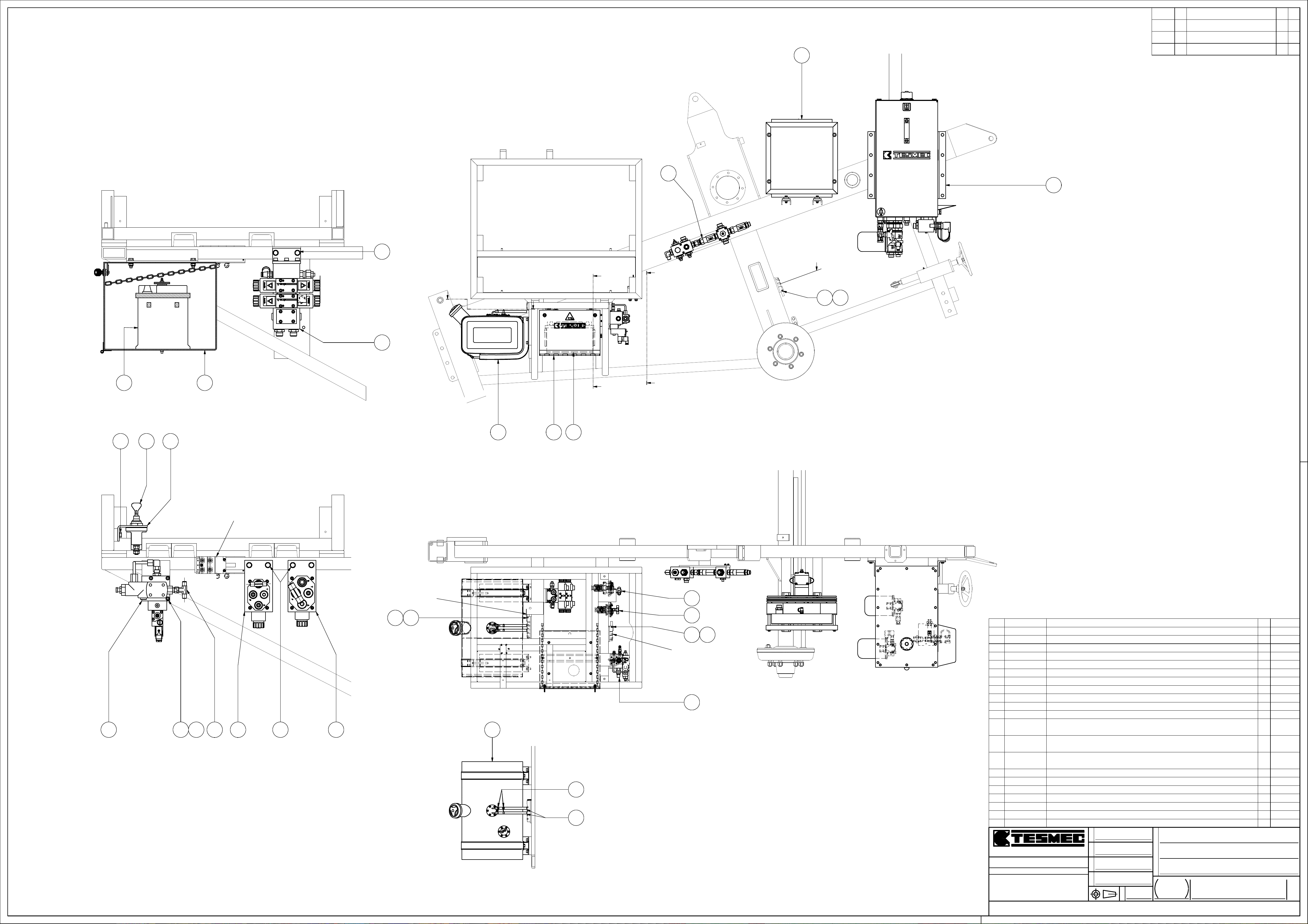
DATE
SYM
REVISION RECORD
CKDR
.
.
2
.
6
1
Sezione "A-A" ( 1 : 5 )
¯¯¯¯¯¯¯¯¯¯¯¯¯¯¯¯¯¯¯
17
9
C
C
A
B
CODE V00-2232-014
15
13
17
18
21
10
4
Sezione "B-B" ( 1 : 5 )
¯¯¯¯¯¯¯¯¯¯¯¯¯¯¯¯¯¯¯
CODE V00-2232-014
3 4 18
A
B
11
CODE V00-2232-015
1315
CODE V00-2232-014
12
11
13
15
15
V00-8401-03821
V00-7150-02420
INTERRUTTORE STACCABATTERIA - 12-24 V - 250 A - IP 65 - COBO : 13.007.000.01 [] SWITCH
TUBO GASOLIO D. 14 / 6 CARBOPRES NL20 - LANZAGOMMA [] PIPE
FASCETTA SERRATUBO D. 12 / 20 - ABA : 9751 [] CLAMPV00-7050-04219
V00-1500-00318
H99-8900-00417
H88-1006-00216
BATTERIA 100 Ah 12 V - EN 760 A -B.325-L.175-H POLI 205-EXIDE:600/0 [] BATTERY
VITE 0274 08 16 - M 8 x 16 - 8 - Z - WURTH [] BOLT
ROSETTA - UNI 1751 - A - 6 - Z [] WASHER
1
0.3 kg
2
4
1
8
3
0 kg
0 kg
9.7 kg
0 kg
0 kg
0 kg9ROSETTA - UNI 1751 - A - 4 - Z [] WASHERH88-1004-001
H56-1006-09014
VITE - M 6 x 90 - ISO 4762 - 8.8 - Z [] BOLT
3
0 kg
0 kg9VITE - M 4 x 20 - ISO 4762 - 8.8 - Z [] BOLTH56-1004-02013
5
11
D00-0012910
A99-103739
F05-0019-00612
7 8175 16 14
3
A99-103728
RACCORDO A T - 1/2" GAS - M - F GIREVOLE - M [] FITTING
SUPPORTO STACCABATTERIE 50 x 70 x 95 [] SUPPORT
ASSIEME BASE MULTIPLA CETOP 03 (3) V00-7200-016 - N°1 EV-V00-6100-206 - N°1
EV-V00-6100-207 - N°1 PIASTRA CHIUSURA [] ASSEMBLY
ASSIEME PIASTRA - BA 302 - ELETTRO-VALVOLA V00-6100-211 - PORTAPIASTRA D99-10027 []
1
0.3 kg
0.1 kg2RACCORDO A T - 1/4" GAS - M - F GIREVOLE - M [] FITTINGF05-0019-003
1
0.1 kg
1
1
14 kg
5.2 kg
ASSEMBLY
7
A99-10371
ASSIEME PIASTRA - BA 202 - ELETTRO-VALVOLA V00-6100-212 - PORTAPIASTRA D99-10033 []
1
3.6 kg
ASSEMBLY
1
6.7 kg
1
1
1
1
1
7 kg
17.9 kg
22.3 kg
34.2 kg
96.4 kg
WEIGHTQTYDESCRIPTIONCODE
Sezione "C-C" ( 1 : 10 )
¯¯¯¯¯¯¯¯¯¯¯¯¯¯¯¯¯¯¯
19
20
5
4
1
A99-101406
A99-10006
A26-00003
A14-000243
A14-000232
A14-00022
ASSIEME BLOCCHETTO - D99-10002 - D99-10094 - IN - OUT RADIATORE OLIO [] ASSEMBLY
ASSIEME BLOCCO REGOLAZIONE TIRO - CON VALVOLA HAWE PMVP4-43/12 [] ASSEMBLY
ASSIEME CASSETTA 1 BATTERIA - Larg.390 - Prof.360 - Alt.283 [] ASSEMBLY
ASSIEME SERBATOIO CARBURANTE 50 L - Pescante Recupero ø6x1 [] ASSEMBLY
ASSIEME RADIATORE OLIO x AFS 303 300 [] ASSEMBLY
ASSIEME SERBATOIO OLIO x AFS 303 300 [] ASSEMBLY
ITEM
O
O
O
O
T
T
T
T
S
S
S
S
I
I
I
I
V
V
V
V
.
.
.
.
S
S
S
S
I
I
I
GGGGRRRRAAAASSSSSSSSOOOOBBBBBBBBIIIIOOOO ((((BBBBGGGG)))) TTTTeeeellll....000033335555////4444222233332222999911111111 ---- FFFFaaaaxxxx 000033335555////4444555522222222444444445555
EEEENNNNDDDDIIIINNNNEEEE GGGG ((((BBBBGGGG)))) TTTTeeeellll....000033335555////888822225555000022224444 ---- FFFFaaaaxxxx 000033335555////888822226666333377775555
TTTTUUUUTTTTTTTTEEEE LLLLEEEE NNNNOOOORRRRMMMMEEEE RRRRIIIICCCCHHHHIIIIAAAAMMMMAAAATTTTEEEE SSSSIIII IIIINNNNTTTTEEEENNNNDDDDOOOONNNNOOOO
NNNNEEEELLLLLLLLAAAA LLLLOOOORRRROOOO UUUULLLLTTTTIIIIMMMMAAAA EEEEDDDDIIIIZZZZIIIIOOOONNNNEEEE....
SSSSAAAALLLLDDDDAAAATTTTUUUURRRREEEE IIIINNNN AAAACCCCCCCCOOOORRRRDDDDOOOO CCCCOOOONNNN ---- WWWWPPPPSSSS 1111÷÷÷÷9999
GGGGRRRRAAAADDDDOOOO DDDDIIII PPPPRRRREEEECCCCIIIISSSSIIIIOOOONNNNEEEE PPPPEEEERRRR QQQQUUUUOOOOTTTTEEEE LLLLIIIINNNNEEEEAAAARRRRIIII,,,,
AAAANNNNGGGGOOOOLLLLAAAARRRRIIII,,,, GGGGEEEEOOOOMMMMEEEETTTTRRRRIIIICCCCHHHHEEEE NNNNOOOONNNN TTTTOOOOLLLLLLLLEEEERRRRAAAATTTTEEEE
LLLLAAAAVVVV....MMMMEEEECCCCCCCCAAAANNNNIIIICCCCHHHHEEEE
CCCCAAAARRRRPPPPEEEENNNNTTTTEEEERRRRIIIIAAAA
IIIIllll ddddiiiisssseeeeggggnnnnoooo èèèè pppprrrroooopppprrrriiiieeeettttàààà ddddeeeellllllllaaaa TTTTEEEESSSSMMMMEEEECCCC ssss....pppp....aaaa.... AAAA tttteeeerrrrmmmmiiiinnnniiii ddddiiii lllleeeeggggggggeeee ssssiiii vvvviiiieeeettttaaaa ttttaaaassssssssaaaattttiiiivvvvaaaammmmeeeennnntttteeee llllaaaa rrrriiiipppprrrroooodddduuuuzzzziiiioooonnnneeee eeee llllaaaa ddddiiiivvvvuuuullllggggaaaazzzziiiioooonnnneeee aaaa tttteeeerrrrzzzziiii....
UUUUNNNNIIII EEEENNNN 22222222777766668888----ffff HHHH
UUUUNNNNIIII EEEENNNN 22222222777766668888----cccc KKKK
I
D
D
D
D
A
A
A
A
T
T
T
T
A
A
A
A
30/06/2014
D
D
D
D
O
O
O
O
S
S
S
S
E
E
E
E
P
P
P
P
Foresti P.
217,98 kg
A
A
A
A
L
L
L
L
A
A
A
A
1.10
C
C
C
C
S
S
S
S
E
E
E
E
N
N
N
N
O
O
O
O
ARGANO FRENO SINGOLO
I
I
I
I
Z
Z
Z
Z
A
A
A
A
N
N
N
N
I
I
I
I
M
M
M
M
AFS 303 320 - PULL 25 kN
O
O
O
O
N
N
N
N
E
E
E
E
D
D
D
D
ASSIEME ALIMENTAZIONE .
FFFFOOOOGGGGLLLLIIIIOOOO
1 / 1
NNNNUUUUMMMMEEEERRRROOOO DDDDIIIISSSSEEEEGGGGNNNNOOOO
A14-00042
A1
Page 55
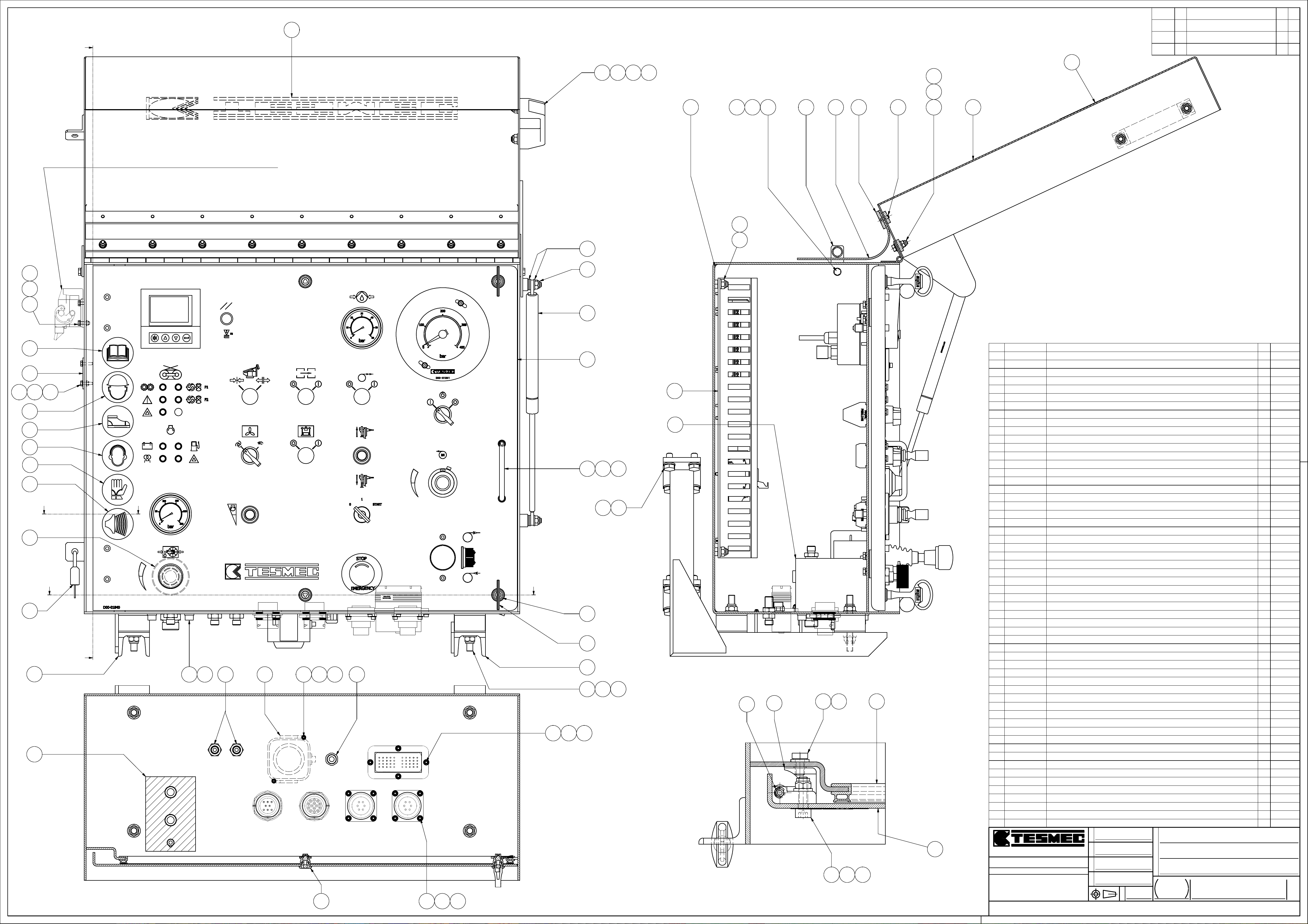
DATE
SYM
REVISION RECORD
CKDR
A
CONNESSIONE REGISTRATORE DI TIRO - DLR 300
11
48 21 31 26
.
.
.
11
30
25
8
163025
4
2238
37
75
24
29
13
55
6
132924
53
52
56
54
57
C C
42
51
A
9
3
21 35
12
44
18 23 28
50
39
19 24 29
N°3+1
31
26
43
2
14
49
BB
50
47
10
40 27 32
19 24 29
Sezione "B-B"
33
1736
35
Sezione "A-A"
26
57
V00-9800-023
56
V00-9800-005
55
V00-9800-00354
V00-9800-00253
1
V00-9800-00152
51
V00-9040-04550
V00-9040-02349
3
V00-9040-02248
ADESIVO - D. 50 SIRENA [] STICKER
ADESIVO D. 50 OBBLIGO CUFFIE PROTETTIVE [] STICKER
ADESIVO D. 50 LETTURA MANUALE [] STICKERV00-9800-004
ADESIVO D. 50 GUANTI PROTETTIVI [] STICKER
ADESIVO D. 50 CASCO PROTEZIONE [] STICKER
ADESIVO D. 50 CALZATURE SICUREZZA [] STICKER
LUCCHETTO + CHIAVE - CISA 21010-30 KA D. 5 [] PADLOCKV00-9040-052
CHIUSURA CROMATA - EMKA - D.20 - GH=13.5 - H=13.5 - CH. TRIANG. 6.5 [] LOCKING
MANIGLIA - ELESA : GN425-10-88-CR [] HANDLE
MANIGLIA - ELESA : M.443/140-8-CH [] HANDLE
47
V00-9010-05346
ANELLO - DIN 7434 - 4 - E [] RING
45
V00-8401-04244
V00-6520-00343
V00-5305-00442
41
V00-5305-003
AVVISATORE ACUSTICO 12 V 129 dB - IP 54 [] HORN
MOLLA A GAS STABILUS LIFT-O-MAT 094781 - 35 Kg - Corsa: 160 L. aperta: 405 [] SPRING
GALLEGGIANTE x INFILZADORA - FERRAMENTA MONTANARI : Art.954 Cod.34037 [] FLOAT
GUARNIZIONE AUTOBLOCCANTE - EMKA : 1011-06 [] SEAL
ANTIVIBRANTE CILINDRICO D. 50 h: 30 M-M - Filettatura: M10 [] RUBBER MOUNTV00-4501-02140
V00-2231-04839
V00-1630-00138
H99-8900-00337
H88-1008-00235
H88-1006-00234
H88-1005-00133
31
H81-1008-002
PRESSACAVO Passo PG9 - MATERIALE PA6.6 - IP 68 [] FITTING
RIVESTIMENTO DI GOMMA (BELTING) sp. 2,6 - IMAS U21 [] COATING
VITE 0274 06 20 - M 6 x 20 - 8 - Z - WURTH [] BOLT
ROSETTA - UNI 1751 - A - 8 - Z [] WASHER
ROSETTA - UNI 1751 - A - 6 - Z [] WASHER
ROSETTA - UNI 1751 - A - 5 - Z [] WASHER
ROSETTA - ISO 7089 - TE - 8 - 100 HV - Z [] WASHER
ROSETTA - ISO 7089 - TE - 6 100 HV - Z [] WASHERH81-1006-00230
H81-1004-00129
H81-1003-00128
H77-1010-01227
H77-1006-00825
H77-1004-00624
H77-1003-00423
H56-1008-02021
H56-1006-02020
H56-1004-01619
H50-1010-02017
ROSETTA - ISO 7089 - TE - 4 100 HV - Z [] WASHER
ROSETTA - ISO 7089 - TE - 3 100 HV - Z [] WASHER
DADO - UNI 7473 - M 10 - GR. 8 - Z - AUTOB. [] LOCKNUT
DADO - UNI 7473 - M 6 - GR. 8 - Z - AUTOB. [] LOCKNUT
DADO - UNI 7473 - M 4 - GR. 8 - Z - AUTOB. [] LOCKNUT
DADO - UNI 7473 - M 3 - GR. 8 - Z - AUTOB. [] LOCKNUT
VITE - ISO 4762 - M 8 x 20 - 8.8 - Z - TCEI - PG [] BOLT
VITE - ISO 4762 - M 6 x 20 - 8.8 - Z - TCEI - PG [] BOLT
VITE - ISO 4762 - M 4 x 16 - 8.8 - Z - TCEI - PG [] BOLT
VITE - M 10 x 20 - ISO 4017 - 8.8 - Z [] BOLT
16
46
45
15 34
41
H50-1006-01015
14
H50-1004-01613
E10-9800-10811
D00-0046910
D00-004689
VITE-ISO 4017-M6x10-8.8-Z [] BOLT
VITE - M 4 x 16 - ISO 4017 - 8.8 - Z [] BOLT
TARGA ADESIVA CANTAMESSA TESMEC L500 [] PLATE
SUPPORTO CRUSCOTTO 118 x 123 x 360 [] SUPPORT
SUPPORTO CRUSCOTTO 118 x 320 x 360 [] SUPPORT
CRUSCOTTO 300 x 575 x 700 - AFS 404 600 [] PANELD00-004668
5
4
1
D00-004467
D00-001146
D00-00111
A99-101473
A15-000402
A15-00024
COPERCHIO CRUSCOTTO 195 x 565 x 730 [] COVER
PIASTRA CHIUSURA 2 x 50 x 120 [] PLATE
FERMO PROTEZIONE BELTING - Allum. - 5 x 30 x 700 [] RETAINER
FERMO CERATA BELTING 20 x 50 x 706.5 [] RETAINERD00-00110
ASSIEME BLOCCHETTO CRUSCOTTO - D99-10003 [] ASSEMBLY
ASSIEME PANNELLO STRUMENTI x AFS 303 300 [] ASSEMBLY
ASSIEME PIASTRA P/COMPONENTI x AFS 303 300 [] ASSEMBLY
ITEM
O
O
O
20 30 25
Sezione "C-C"
O
T
T
T
T
S
S
S
S
I
I
I
I
V
V
V
V
.
.
.
.
S
S
S
S
I
I
I
2
GGGGRRRRAAAASSSSSSSSOOOOBBBBBBBBIIIIOOOO ((((BBBBGGGG)))) TTTTeeeellll....000033335555////4444222233332222999911111111 ---- FFFFaaaaxxxx 000033335555////4444555522222222444444445555
EEEENNNNDDDDIIIINNNNEEEE GGGG ((((BBBBGGGG)))) TTTTeeeellll....000033335555////888822225555000022224444 ---- FFFFaaaaxxxx 000033335555////888822226666333377775555
TTTTUUUUTTTTTTTTEEEE LLLLEEEE NNNNOOOORRRRMMMMEEEE RRRRIIIICCCCHHHHIIIIAAAAMMMMAAAATTTTEEEE SSSSIIII IIIINNNNTTTTEEEENNNNDDDDOOOONNNNOOOO
NNNNEEEELLLLLLLLAAAA LLLLOOOORRRROOOO UUUULLLLTTTTIIIIMMMMAAAA EEEEDDDDIIIIZZZZIIIIOOOONNNNEEEE....
SSSSAAAALLLLDDDDAAAATTTTUUUURRRREEEE IIIINNNN AAAACCCCCCCCOOOORRRRDDDDOOOO CCCCOOOONNNN ---- WWWWPPPPSSSS 1111÷÷÷÷9999
GGGGRRRRAAAADDDDOOOO DDDDIIII PPPPRRRREEEECCCCIIIISSSSIIIIOOOONNNNEEEE PPPPEEEERRRR QQQQUUUUOOOOTTTTEEEE LLLLIIIINNNNEEEEAAAARRRRIIII,,,,
AAAANNNNGGGGOOOOLLLLAAAARRRRIIII,,,, GGGGEEEEOOOOMMMMEEEETTTTRRRRIIIICCCCHHHHEEEE NNNNOOOONNNN TTTTOOOOLLLLLLLLEEEERRRRAAAATTTTEEEE
LLLLAAAAVVVV....MMMMEEEECCCCCCCCAAAANNNNIIIICCCCHHHHEEEE
CCCCAAAARRRRPPPPEEEENNNNTTTTEEEERRRRIIIIAAAA
IIIIllll ddddiiiisssseeeeggggnnnnoooo èèèè pppprrrroooopppprrrriiiieeeettttàààà ddddeeeellllllllaaaa TTTTEEEESSSSMMMMEEEECCCC ssss....pppp....aaaa.... AAAA tttteeeerrrrmmmmiiiinnnniiii ddddiiii lllleeeeggggggggeeee ssssiiii vvvviiiieeeettttaaaa ttttaaaassssssssaaaattttiiiivvvvaaaammmmeeeennnntttteeee llllaaaa rrrriiiipppprrrroooodddduuuuzzzziiiioooonnnneeee eeee llllaaaa ddddiiiivvvvuuuullllggggaaaazzzziiiioooonnnneeee aaaa tttteeeerrrrzzzziiii....
UUUUNNNNIIII EEEENNNN 22222222777766668888----ffff HHHH
UUUUNNNNIIII EEEENNNN 22222222777766668888----cccc KKKK
I
D
D
D
D
A
A
A
A
T
T
T
T
A
A
A
A
29/09/2011
D
D
D
D
O
O
O
O
S
S
S
S
E
E
E
E
P
P
P
P
Foresti P.
71,88 kg
A
A
A
A
L
L
L
L
A
A
A
A
1:2.5
C
C
C
C
S
S
S
S
E
E
E
E
N
N
N
N
O
O
O
O
ARGANO FRENO SINGOLO
I
I
I
I
Z
Z
Z
Z
A
A
A
A
N
N
N
N
I
I
I
I
M
M
M
M
AFS 303 300
O
O
O
O
N
N
N
N
E
E
E
E
D
D
D
D
ASSIEME MOMTAGGIO CRUSCOTTO
FFFFOOOOGGGGLLLLIIIIOOOO
1 / 1
NNNNUUUUMMMMEEEERRRROOOO DDDDIIIISSSSEEEEGGGGNNNNOOOO
A15-00023
1
1
1
1
1
1
1
4
1
1
2
1
1
1
2.3
4
1
1
9
8
4
2
10
17
40
2
8
15
20
2
6
4
12
8
4
8
1
1
1
1
1
1
1
1
1
1
1
0 kg
0 kg
0 kg
0 kg
0 kg
0 kg
0.1 kg
0 kg
0.1 kg
0 kg
0 kg2CHIAVE A TRIANGOLO 6.5 mm - EMKA - 1004-21 [] KEYV00-9040-016
0 kg
0.1 kg2CERNIERA 120 NERA - EMKA : 1110-U86 [] HINGEV00-9000-007
0.2 kg
0.1 kg
0 kg
0.2 kg
0.2 kg
0 kg
0.4 kg
0 kg
0 kg8ROSETTA - UNI 1751 - A - 10 - Z [] WASHERH88-1010-00236
0 kg
0 kg
0 kg
0 kg8ROSETTA - ISO 7089 - TE - 10 100 HV - Z [] WASHERH81-1010-00232
0 kg
0 kg
0 kg
0 kg
0 kg
0 kg8DADO - UNI 7473 - M 8 - GR. 8 - Z - AUTOB. [] LOCKNUTH77-1008-01126
0 kg
0 kg
0 kg
0 kg9VITE - ISO 10642 - M 5 x 16 - 10.9 - Z - TSEI [] BOLTH58-1005-01622
0 kg
0 kg
0 kg
0 kg2VITE - ISO 4762 - M 3 x 10 - 8.8 - Z - TCEI - PG [] BOLTH56-1003-01018
0 kg
0 kg2VITE - ISO 4017 - M 6 x 20 - 8.8 - Z [] BOLTH50-1006-020
0 kg
0 kg2VITE-ISO 4017-M5x12-8.8-Z [] BOLTH50-1005-012
0 kg
0 kg2PASSAPARETE DIRITTO 1/4" GAS - 1/4" GAS [] BULKHEAD CLASSF14-0001-00312
0 kg
2.7 kg
4 kg
29.1 kg
11.4 kg
0.1 kg
0.3 kg
0.5 kg
2.8 kg
8.2 kg
9.6 kg
WEIGHTQTYDESCRIPTIONCODE
A1
Page 56
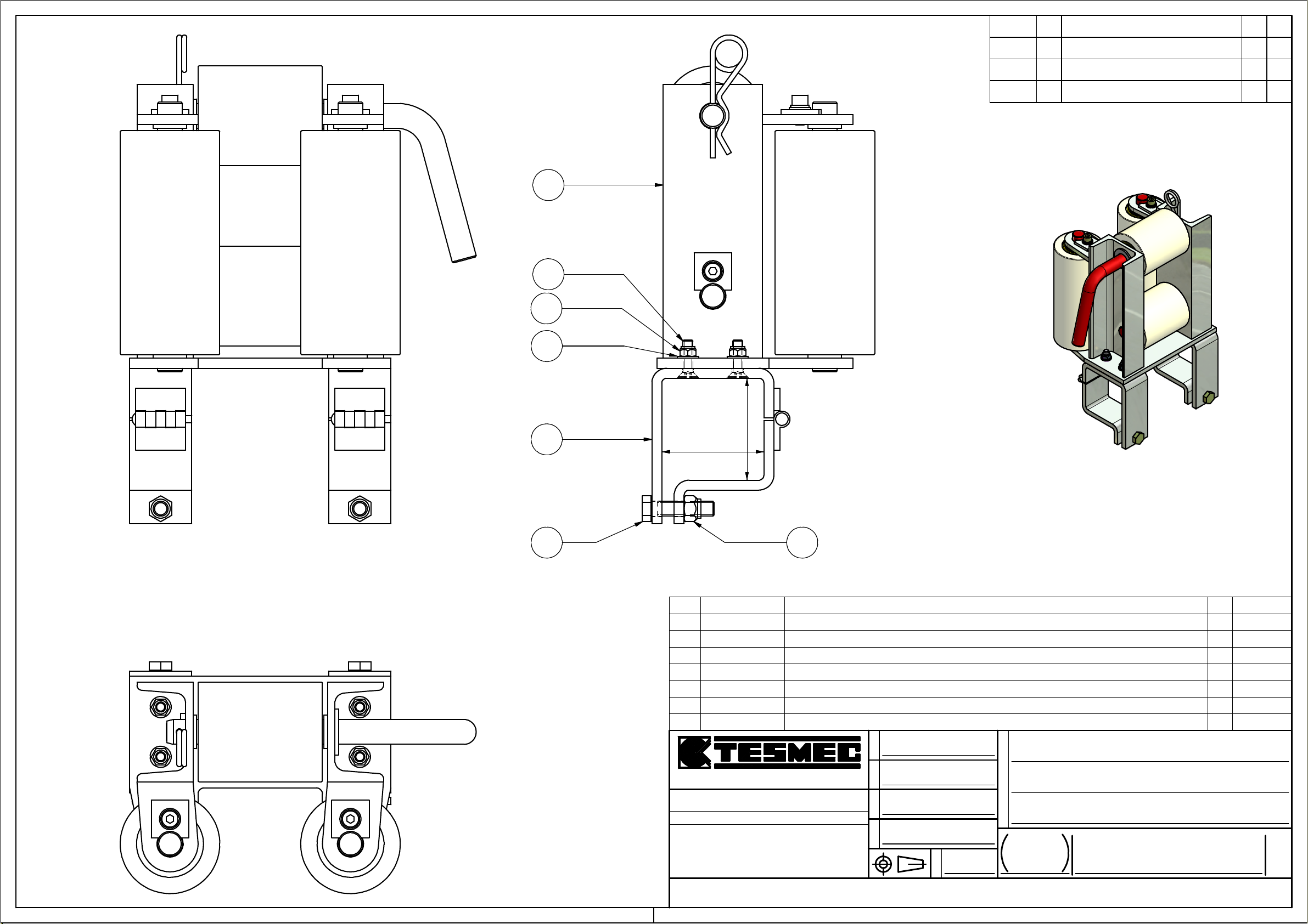
REVISION RECORDSYMDATE
CKDR
.
.
.
1
4
5
7
2
2
82
8
3 6
7
H77-1008-0115
4
H58-1008-030
H77-1012-0156
D00-024452
1
A17-00027
ITEM
GGGGRRRRAAAASSSSSSSSOOOOBBBBBBBBIIIIOOOO ((((BBBBGGGG)))) TTTTeeeellll....000033335555////4444222233332222999911111111 ---- FFFFaaaaxxxx 000033335555////4444555522222222444444445555
EEEENNNNDDDDIIIINNNNEEEE GGGG ((((BBBBGGGG)))) TTTTeeeellll....000033335555////888822225555000022224444 ---- FFFFaaaaxxxx 000033335555////888822226666333377775555
TTTTUUUUTTTTTTTTEEEE LLLLEEEE NNNNOOOORRRRMMMMEEEE RRRRIIIICCCCHHHHIIIIAAAAMMMMAAAATTTTEEEE SSSSIIII IIIINNNNTTTTEEEENNNNDDDDOOOONNNNOOOO
NNNNEEEELLLLLLLLAAAA LLLLOOOORRRROOOO UUUULLLLTTTTIIIIMMMMAAAA EEEEDDDDIIIIZZZZIIIIOOOONNNNEEEE....
SSSSAAAALLLLDDDDAAAATTTTUUUURRRREEEE IIIINNNN AAAACCCCCCCCOOOORRRRDDDDOOOO CCCCOOOONNNN ---- WWWWPPPPSSSS 1111÷÷÷÷9999
GGGGRRRRAAAADDDDOOOO DDDDIIII PPPPRRRREEEECCCCIIIISSSSIIIIOOOONNNNEEEE PPPPEEEERRRR QQQQUUUUOOOOTTTTEEEE LLLLIIIINNNNEEEEAAAARRRRIIII,,,,
AAAANNNNGGGGOOOOLLLLAAAARRRRIIII,,,, GGGGEEEEOOOOMMMMEEEETTTTRRRRIIIICCCCHHHHEEEE NNNNOOOONNNN TTTTOOOOLLLLLLLLEEEERRRRAAAATTTTEEEE
LLLLAAAAVVVV....MMMMEEEECCCCCCCCAAAANNNNIIIICCCCHHHHEEEE
CCCCAAAARRRRPPPPEEEENNNNTTTTEEEERRRRIIIIAAAA
IIIIllll ddddiiiisssseeeeggggnnnnoooo èèèè pppprrrroooopppprrrriiiieeeettttàààà ddddeeeellllllllaaaa TTTTEEEESSSSMMMMEEEECCCC ssss....pppp....aaaa.... AAAA tttteeeerrrrmmmmiiiinnnniiii ddddiiii lllleeeeggggggggeeee ssssiiii vvvviiiieeeettttaaaa ttttaaaassssssssaaaattttiiiivvvvaaaammmmeeeennnntttteeee llllaaaa rrrriiiipppprrrroooodddduuuuzzzziiiioooonnnneeee eeee llllaaaa ddddiiiivvvvuuuullllggggaaaazzzziiiioooonnnneeee aaaa tttteeeerrrrzzzziiii....
UUUUNNNNIIII EEEENNNN 22222222777766668888----ffff HHHH
UUUUNNNNIIII EEEENNNN 22222222777766668888----cccc KKKK
ROSETTA - ISO 7089 - TE - 8 - 100 HV - Z [] WASHERH81-1008-002
DADO - UNI 7473 - M 8 - GR. 8 - Z - AUTOB. [] LOCKNUT
VITE - M 8 x 30 - ISO 10642 - 10.9 - Z - TSEI [] BOLT
DADO - UNI 7473 - M 12 - GR. 8 - Z - AUTOB. [] LOCKNUT
COLLARE SUPPORTO RULLI 50 x 98 x 125 [] CLAMP
ASSIEME RULLIERA SINGOLA - NYLON [] ASSEMBLY
O
O
O
O
T
T
T
T
S
S
S
S
I
I
I
I
V
V
V
V
.
.
.
.
S
S
S
S
I
I
I
I
Foresti P.
D
D
D
D
A
A
A
A
T
T
T
T
A
A
A
A
12/10/2012
D
D
D
D
O
O
O
O
S
S
S
S
14.04 kg
E
E
E
E
P
P
P
P
4
4
4
2
0 kg
0 kg
0 kg
0 kg
0.1 kg2VITE - M 12 x 50 - ISO 4017 - 8.8 - Z [] BOLTH50-1012-0503
2
1.3 kg
1
11.2 kg
WEIGHTQTYDESCRIPTIONCODE
E
E
E
E
N
N
N
A
A
A
A
L
L
L
L
A
A
A
A
C
C
C
C
S
S
S
S
N
O
O
O
O
ARGANI FRENI - FRENI
I
I
I
I
Z
Z
Z
Z
A
A
A
A
N
N
N
N
I
I
I
I
M
M
M
M
VARI - ASSIEME
O
O
O
O
N
N
N
N
E
E
E
E
D
D
D
D
RULLIERA SINGOLA NYLON QUADRO 80
FFFFOOOOGGGGLLLLIIIIOOOO
1 / 1
NNNNUUUUMMMMEEEERRRROOOO DDDDIIIISSSSEEEEGGGGNNNNOOOO
A17-00029
A3
Page 57
25/03/2011 Facoetti
Ing. Oscar
AFS 303 300
PRESETTINGS : EQUIPMENT :
Page 58
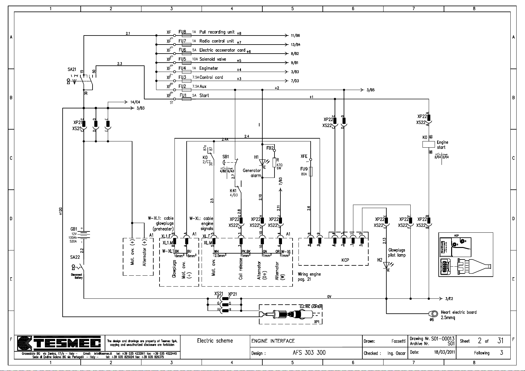
0 1 2
Page 59
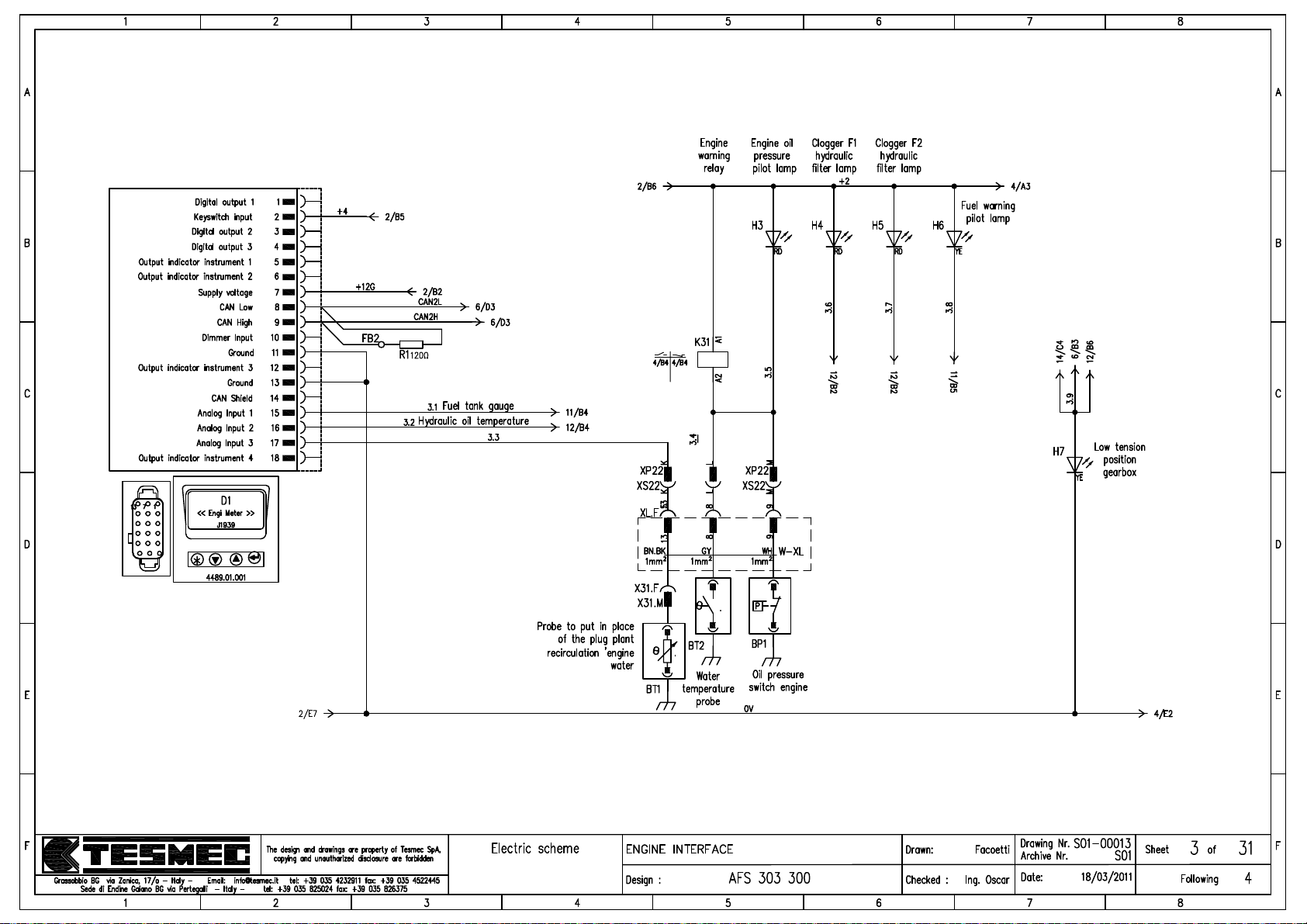
Page 60
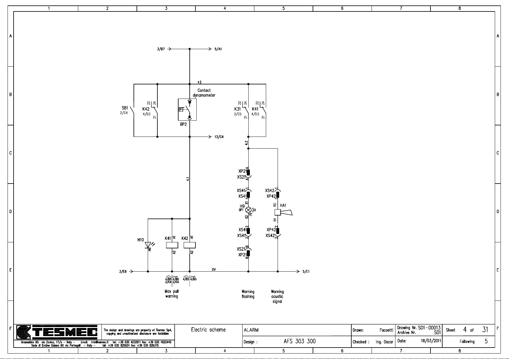
Page 61
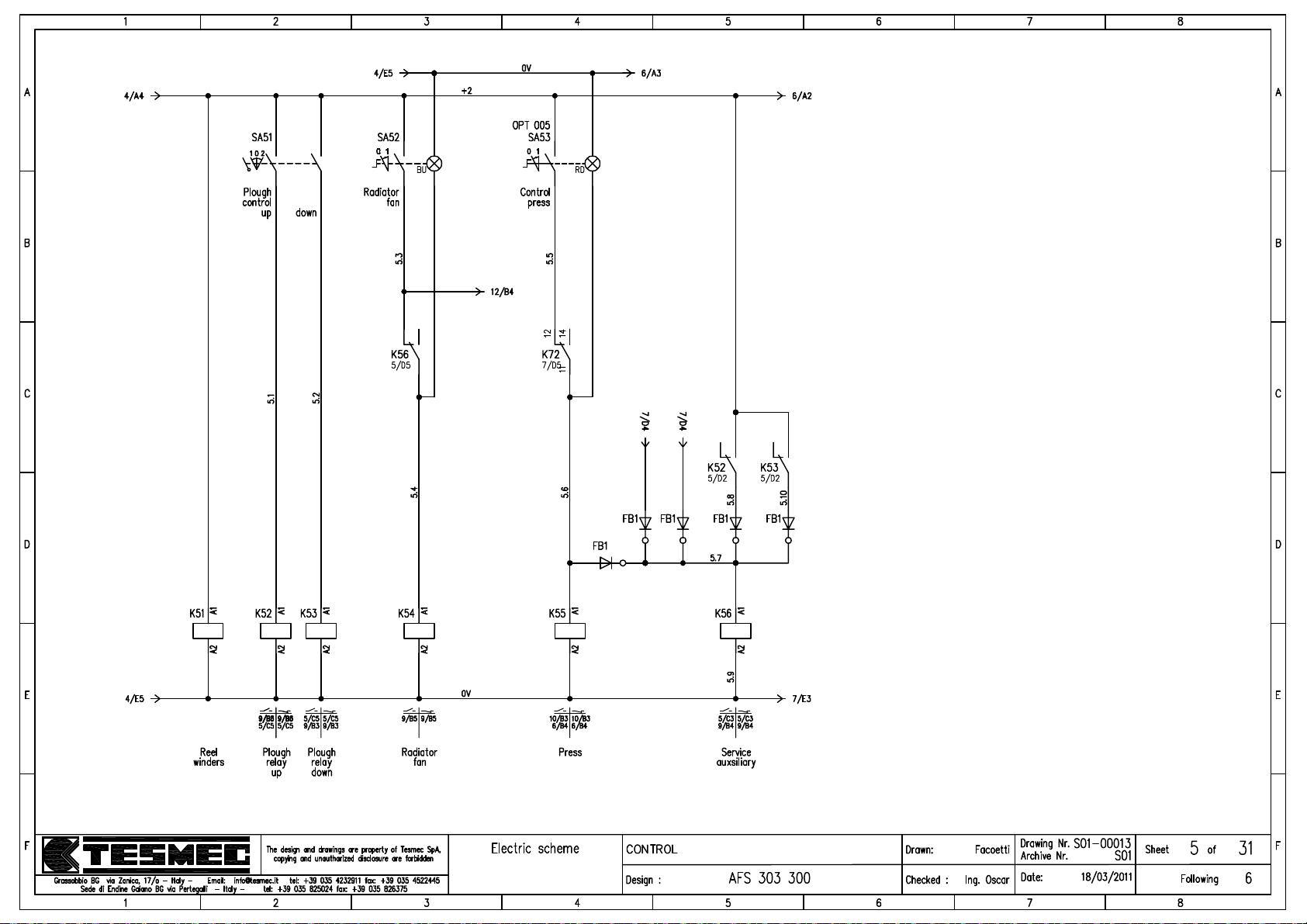
Page 62
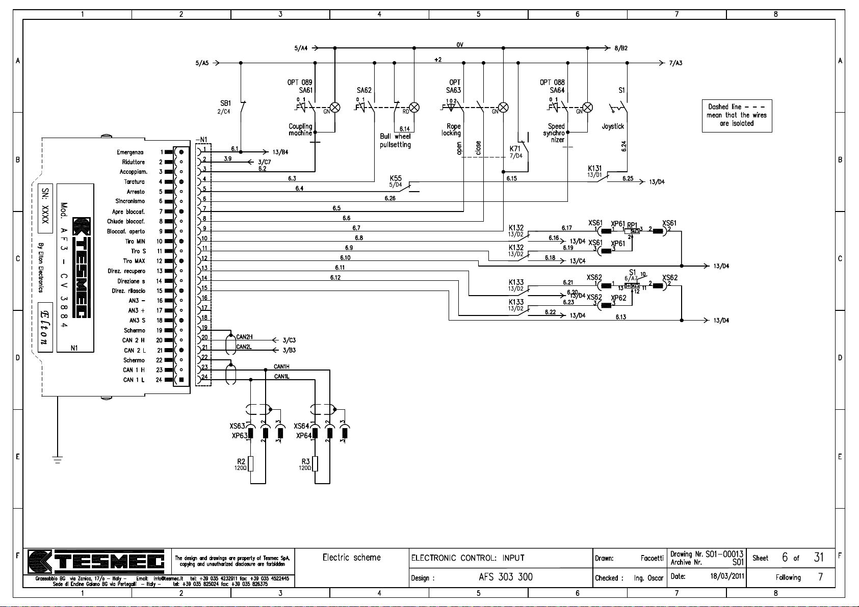
JP1
Page 63
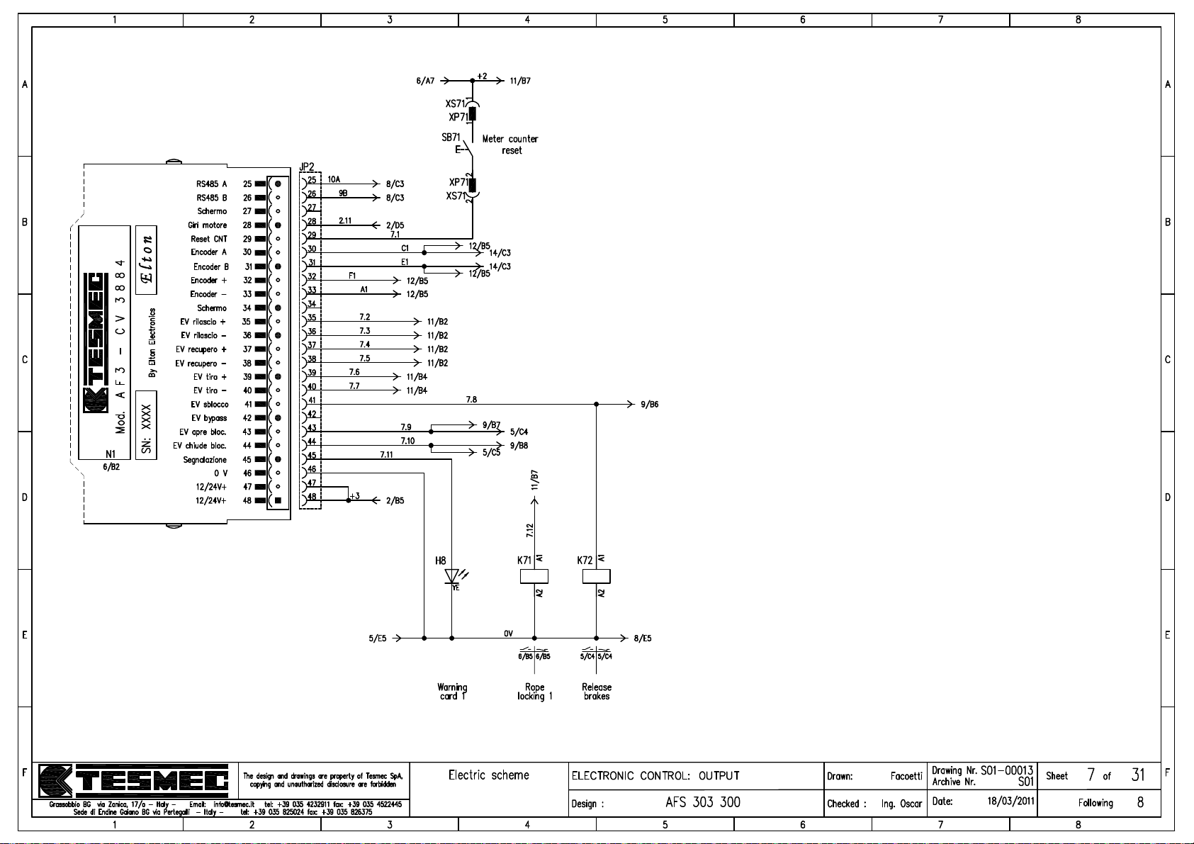
JP2
Page 64
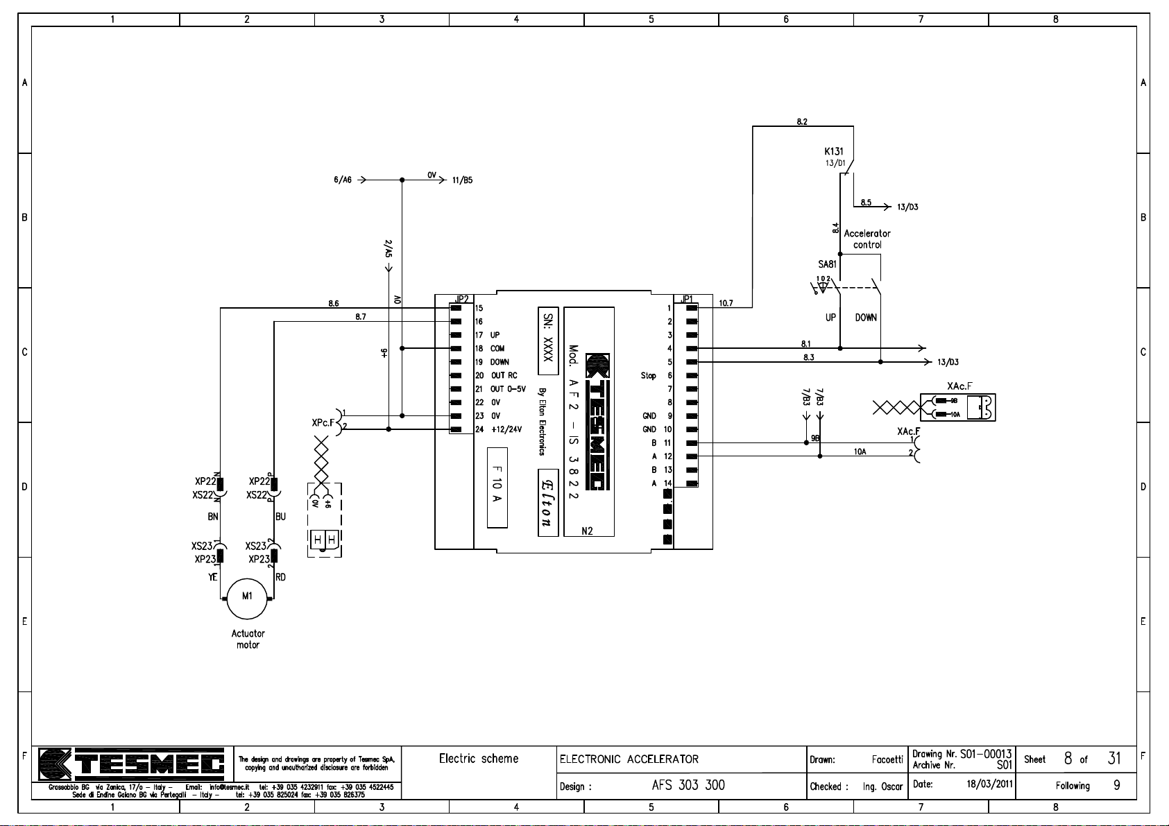
LD1 LD2 LD3 LD4
Page 65
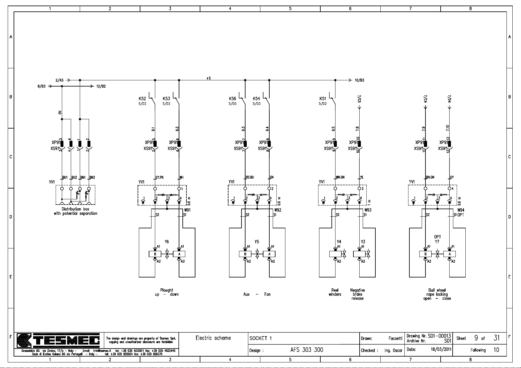
Page 66
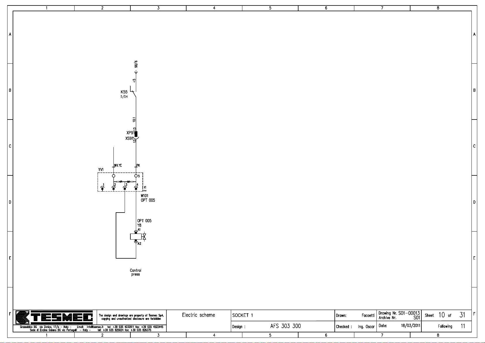
Page 67
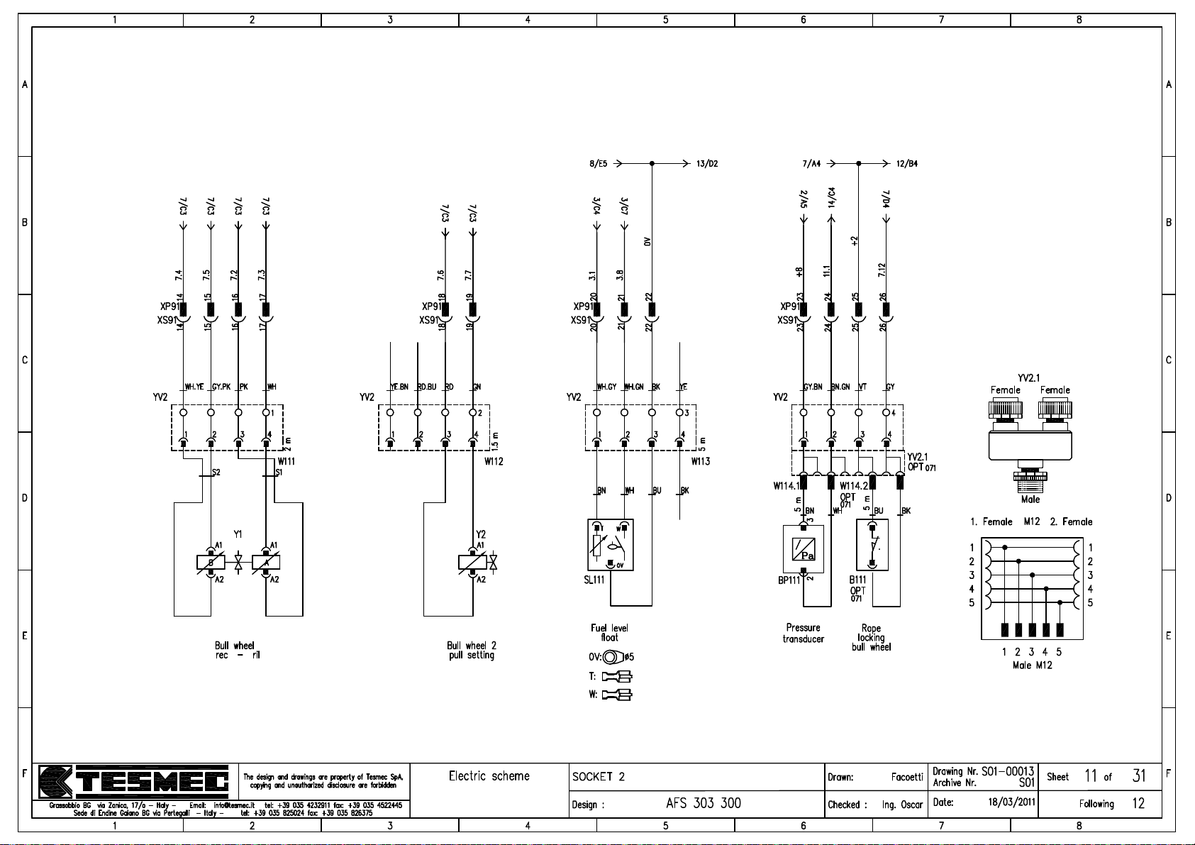
Page 68
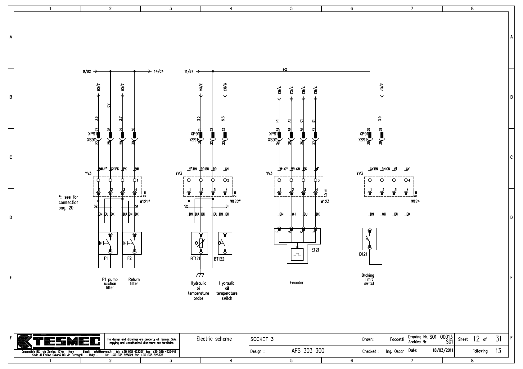
Page 69
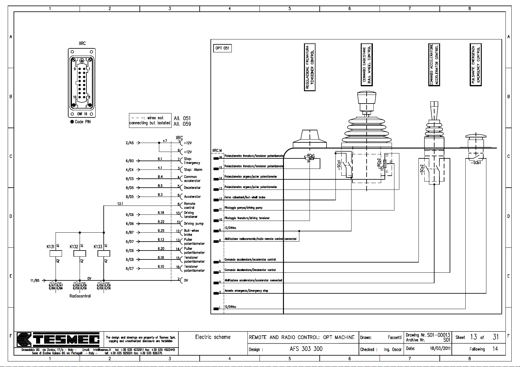
Page 70
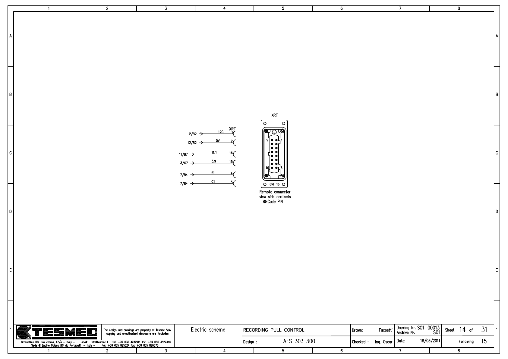
Page 71
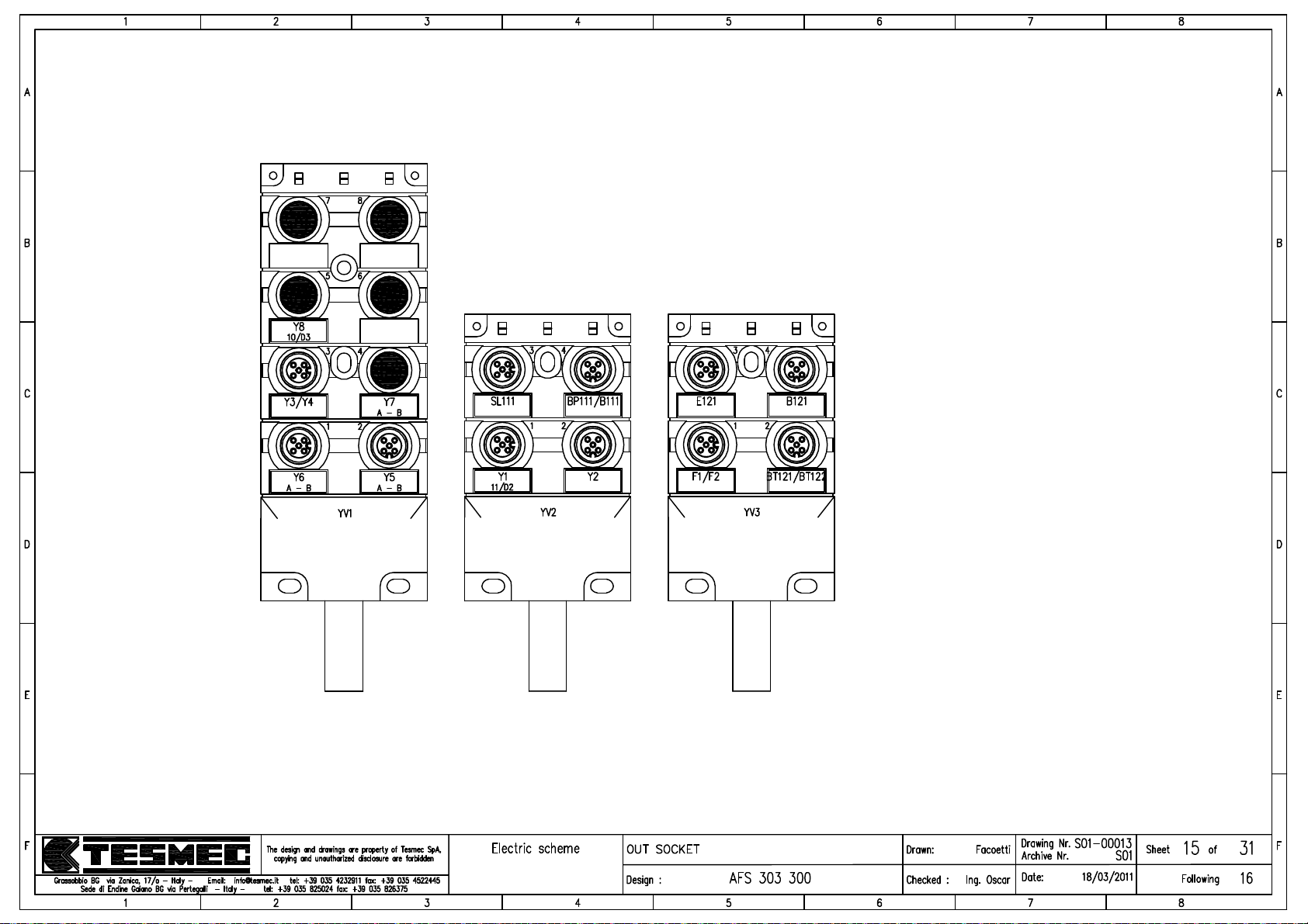
Page 72
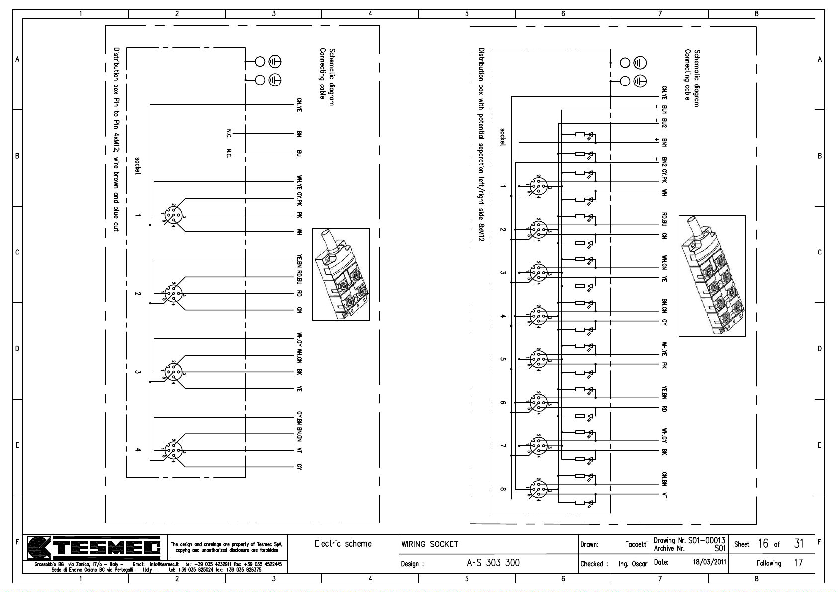
Page 73
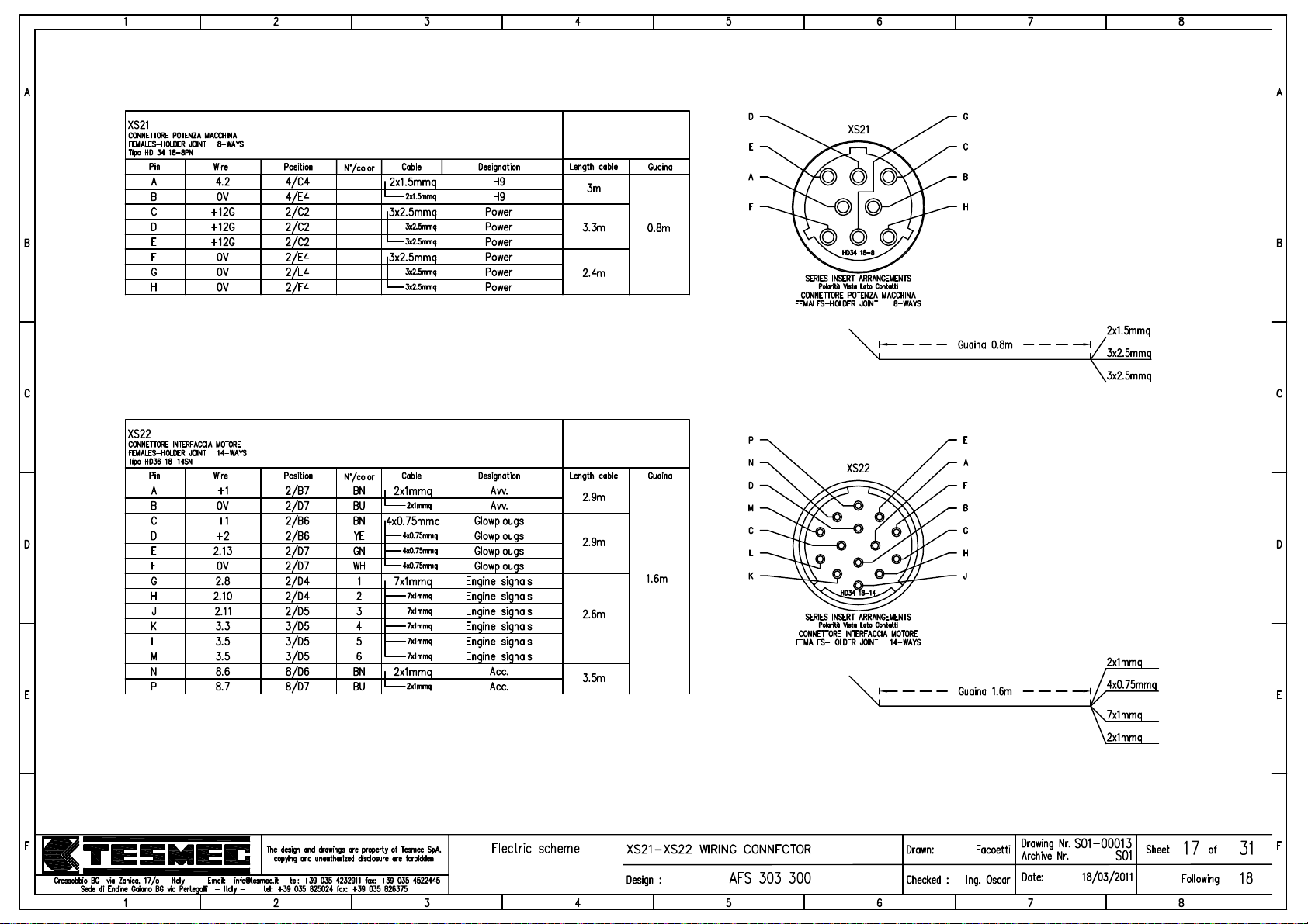
Page 74
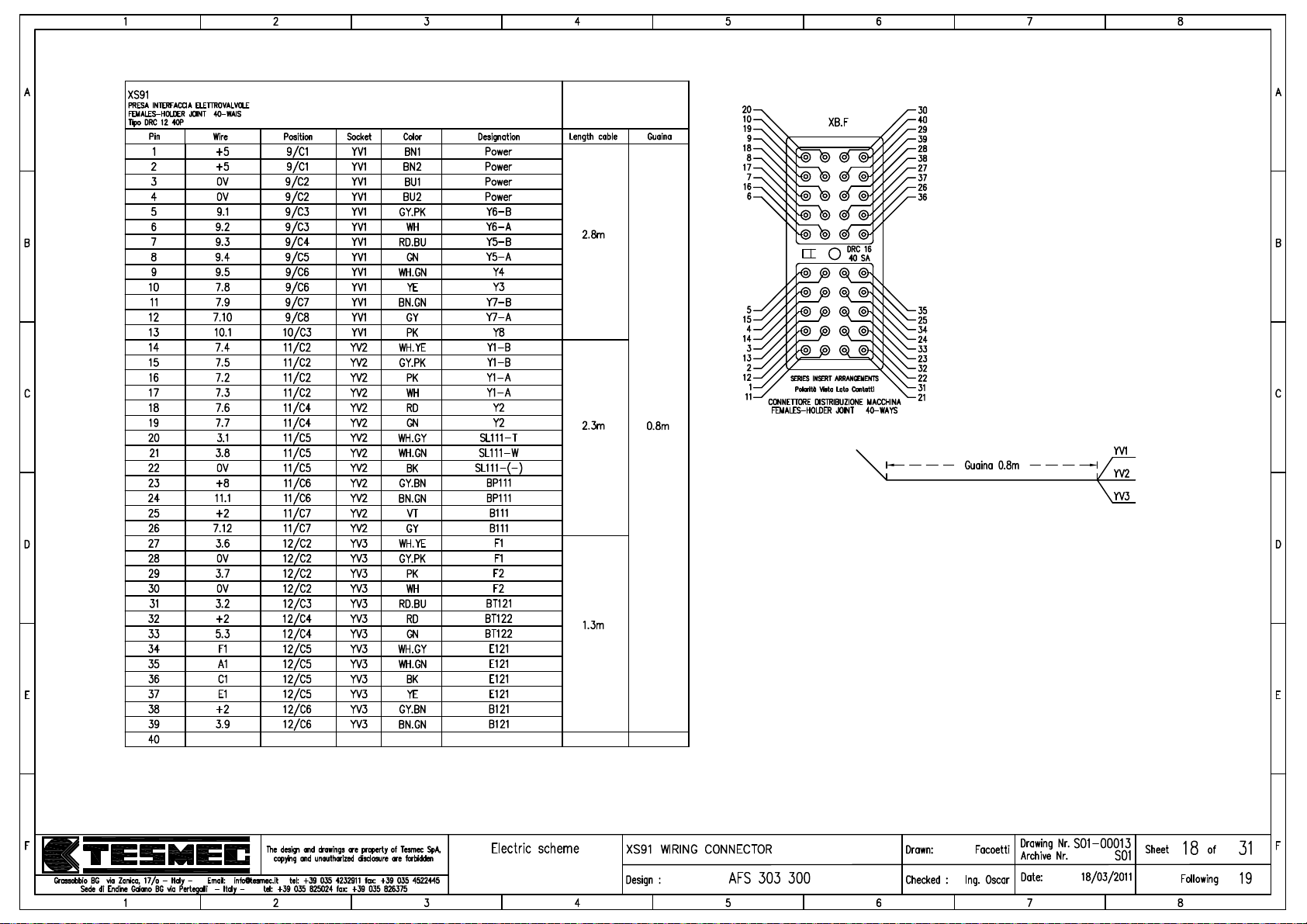
Page 75
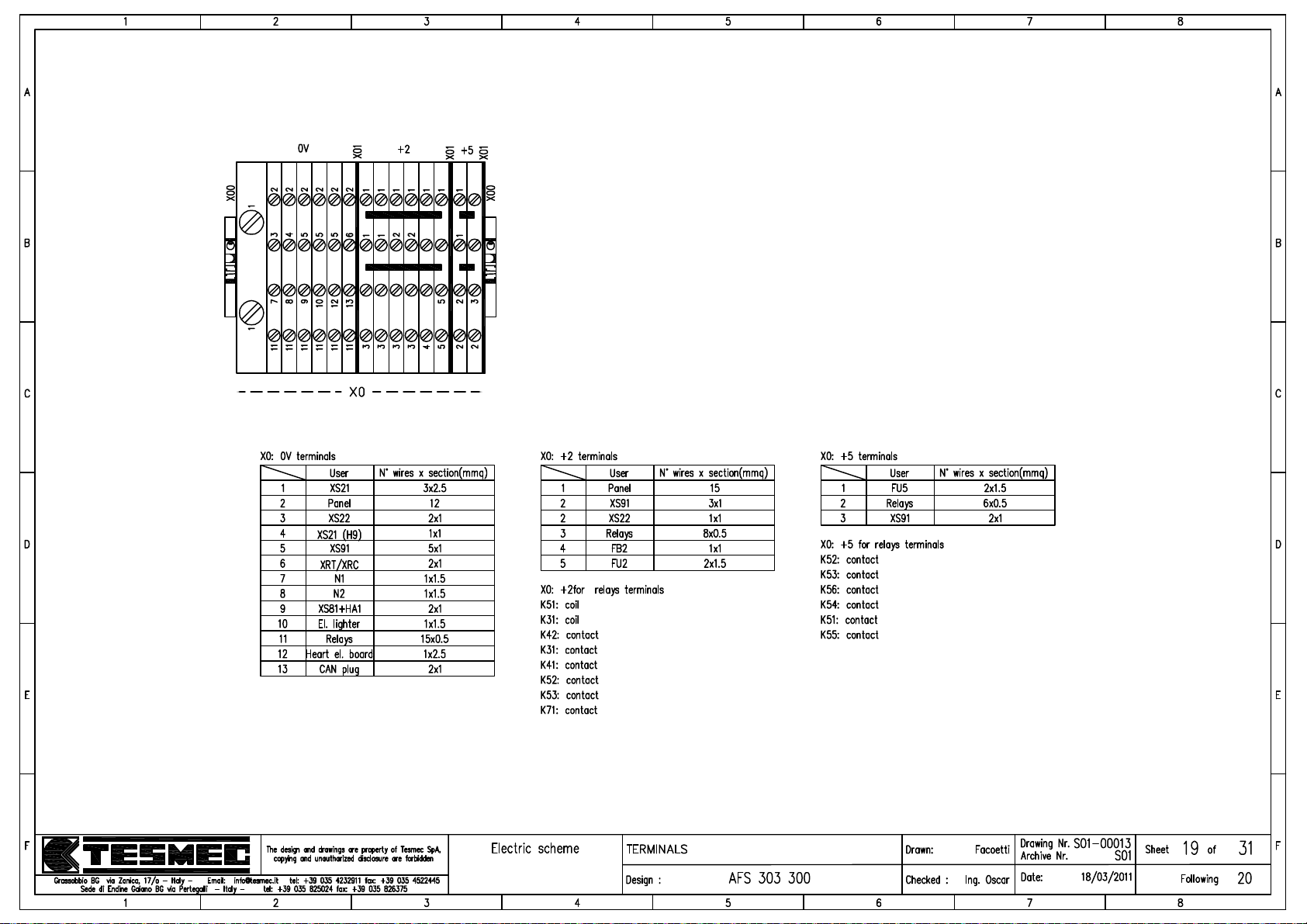
Page 76
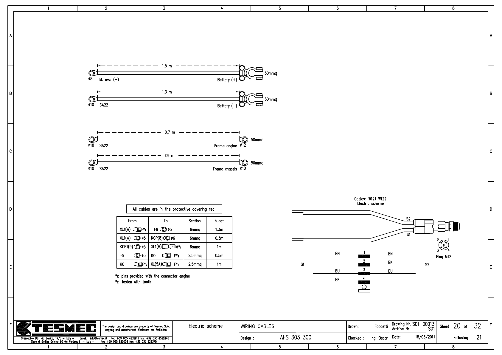
Page 77
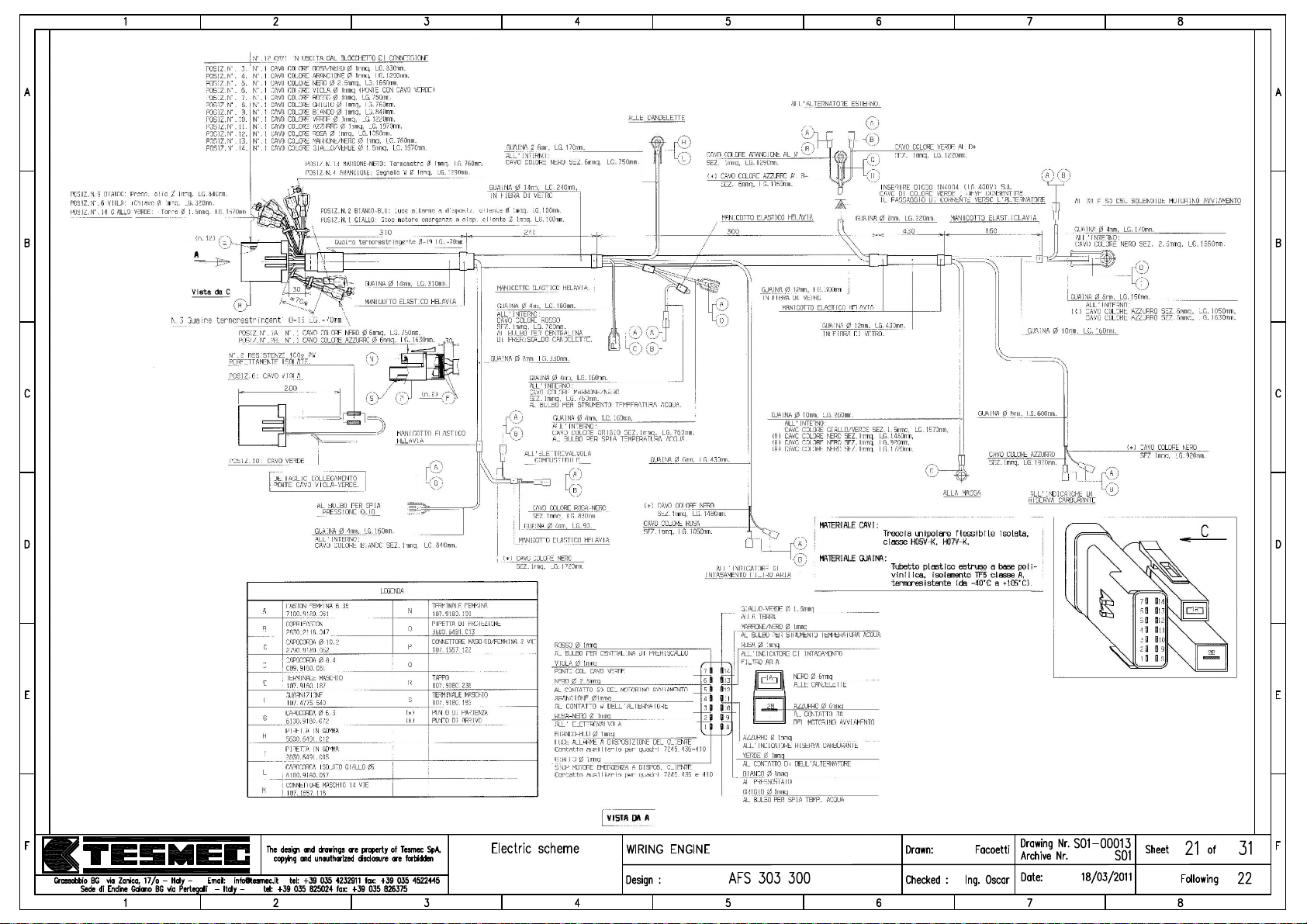
Page 78
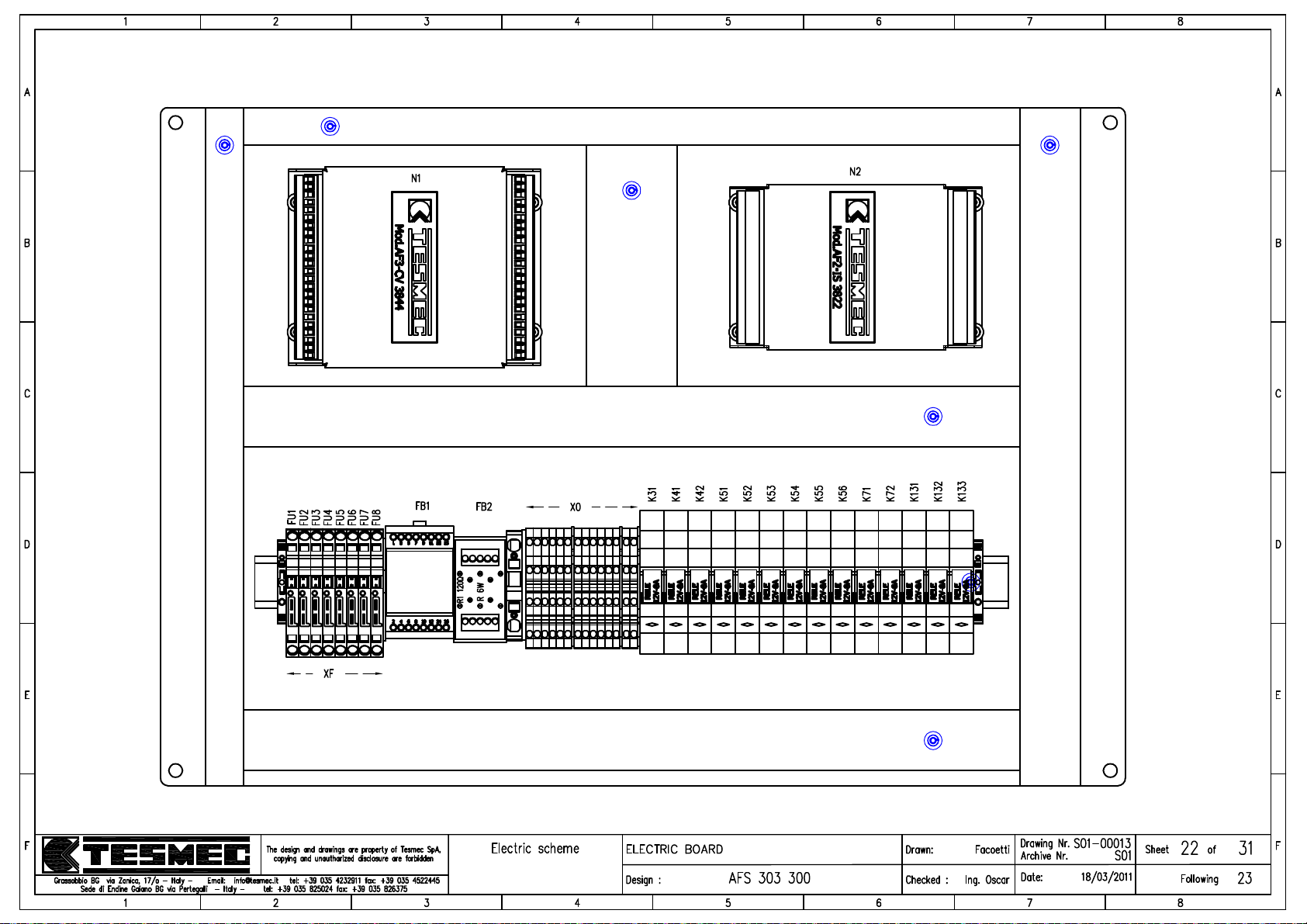
Page 79
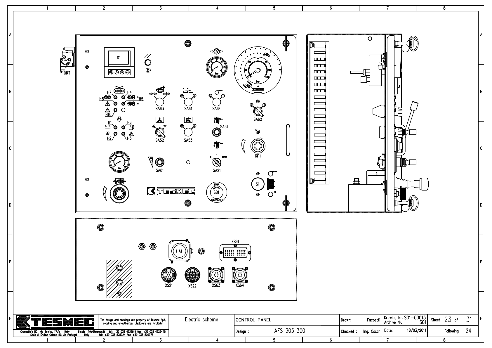
Page 80
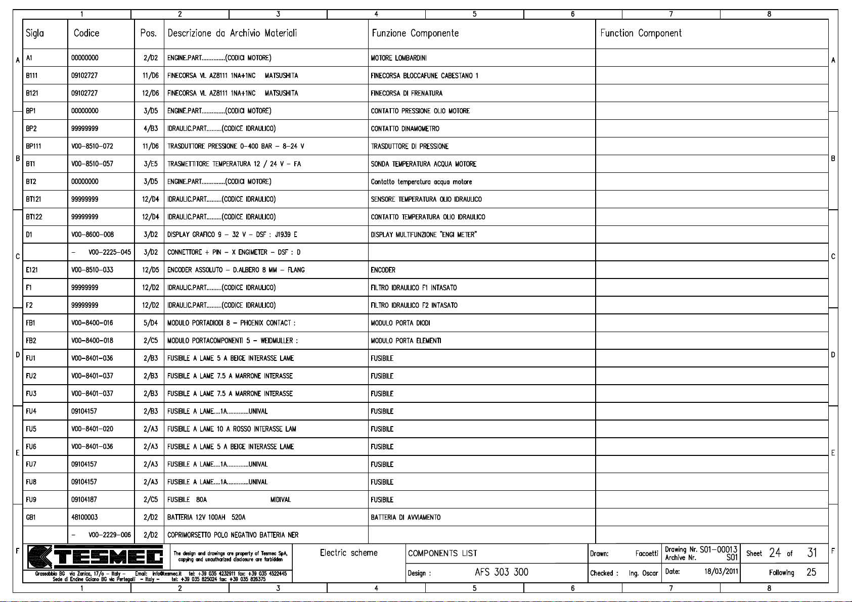
Page 81
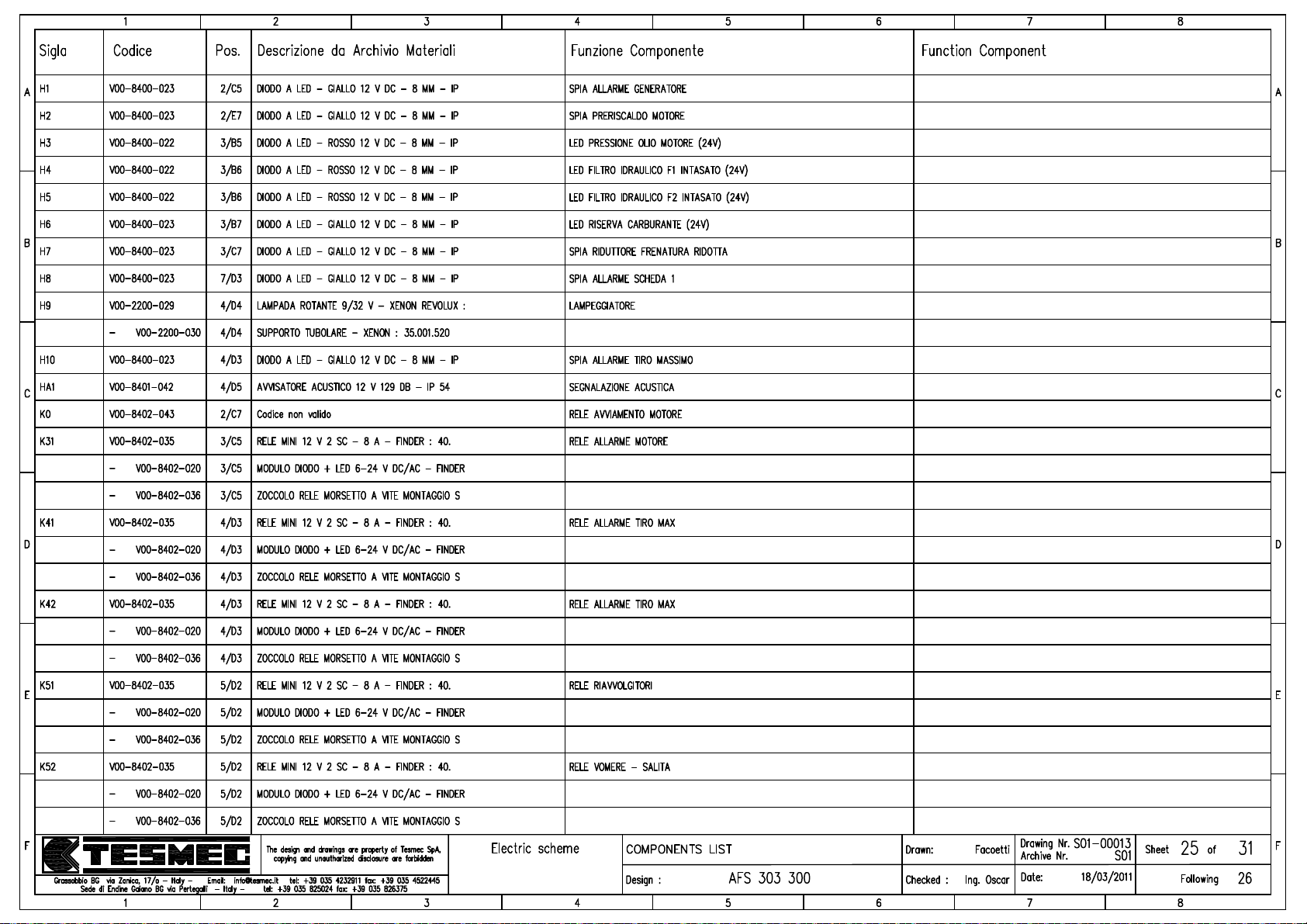
Page 82
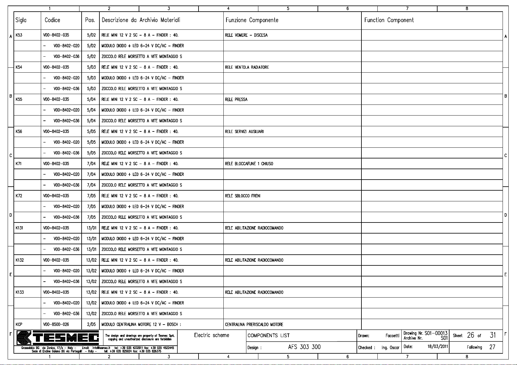
Page 83
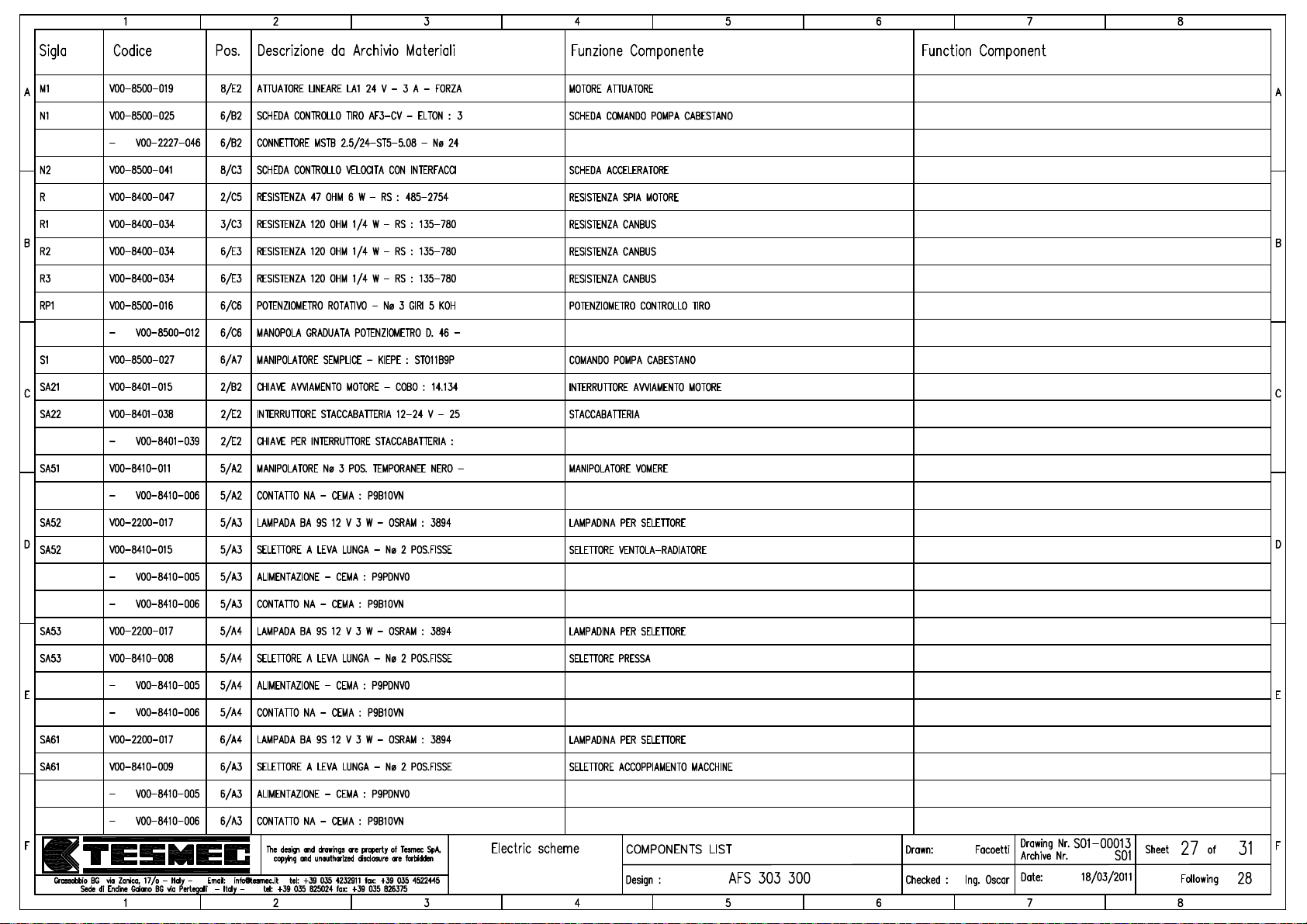
Page 84
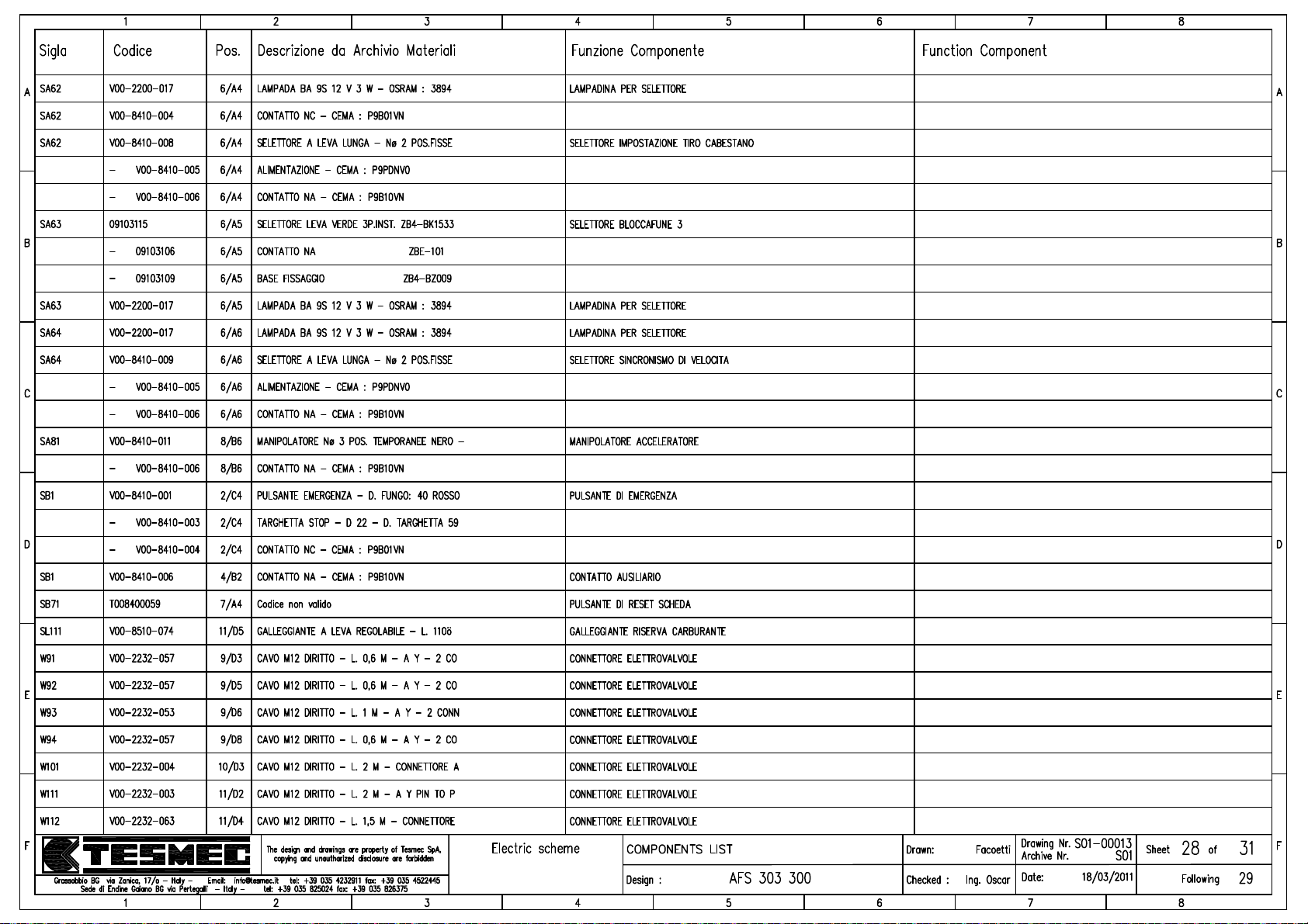
Page 85
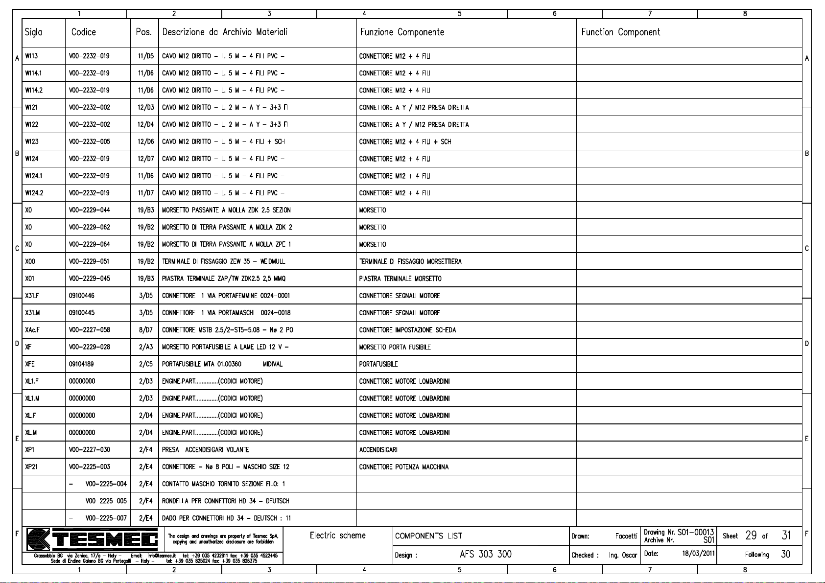
Page 86
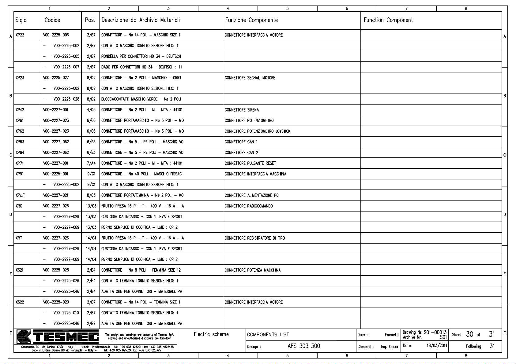
Page 87
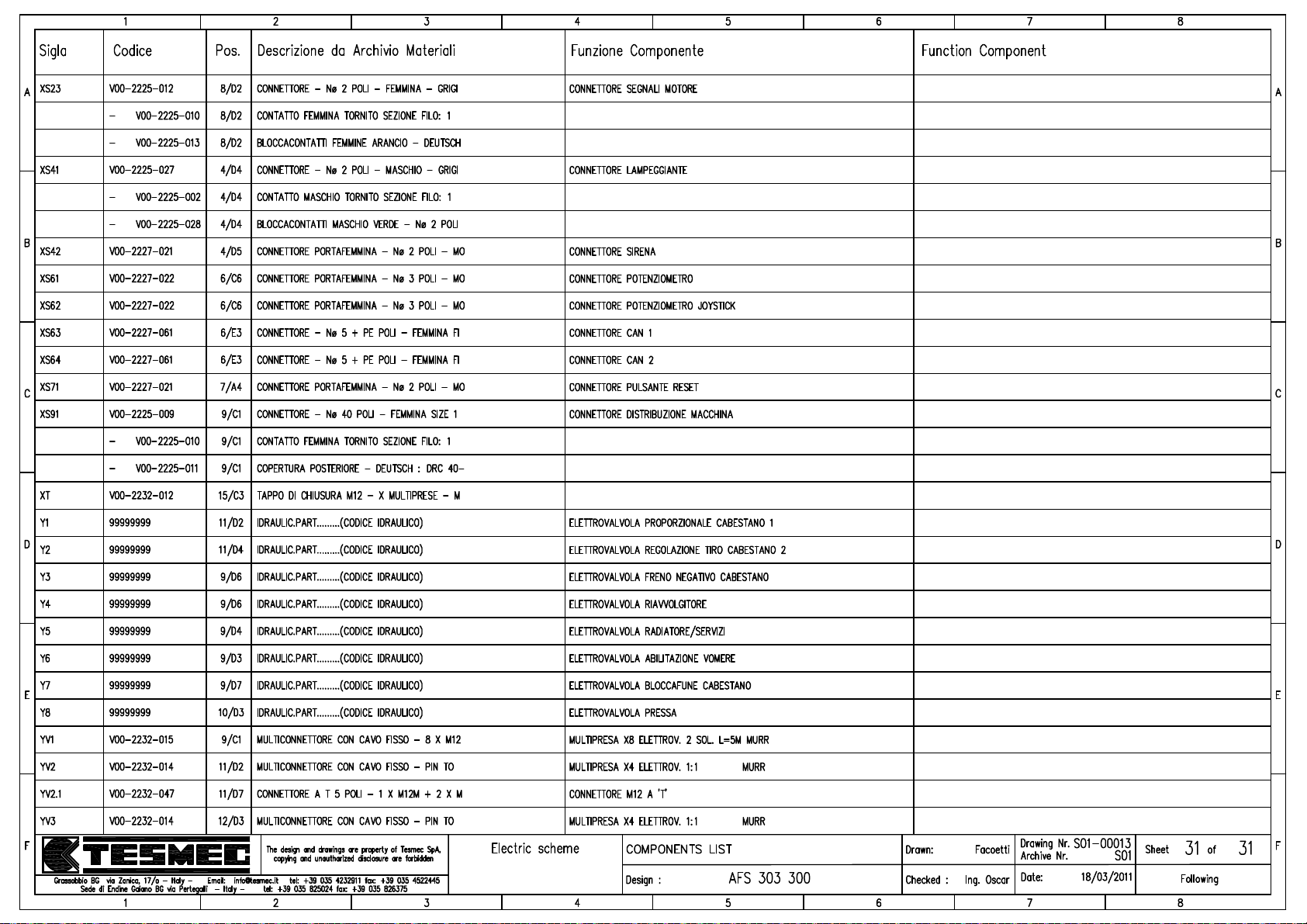
Page 88
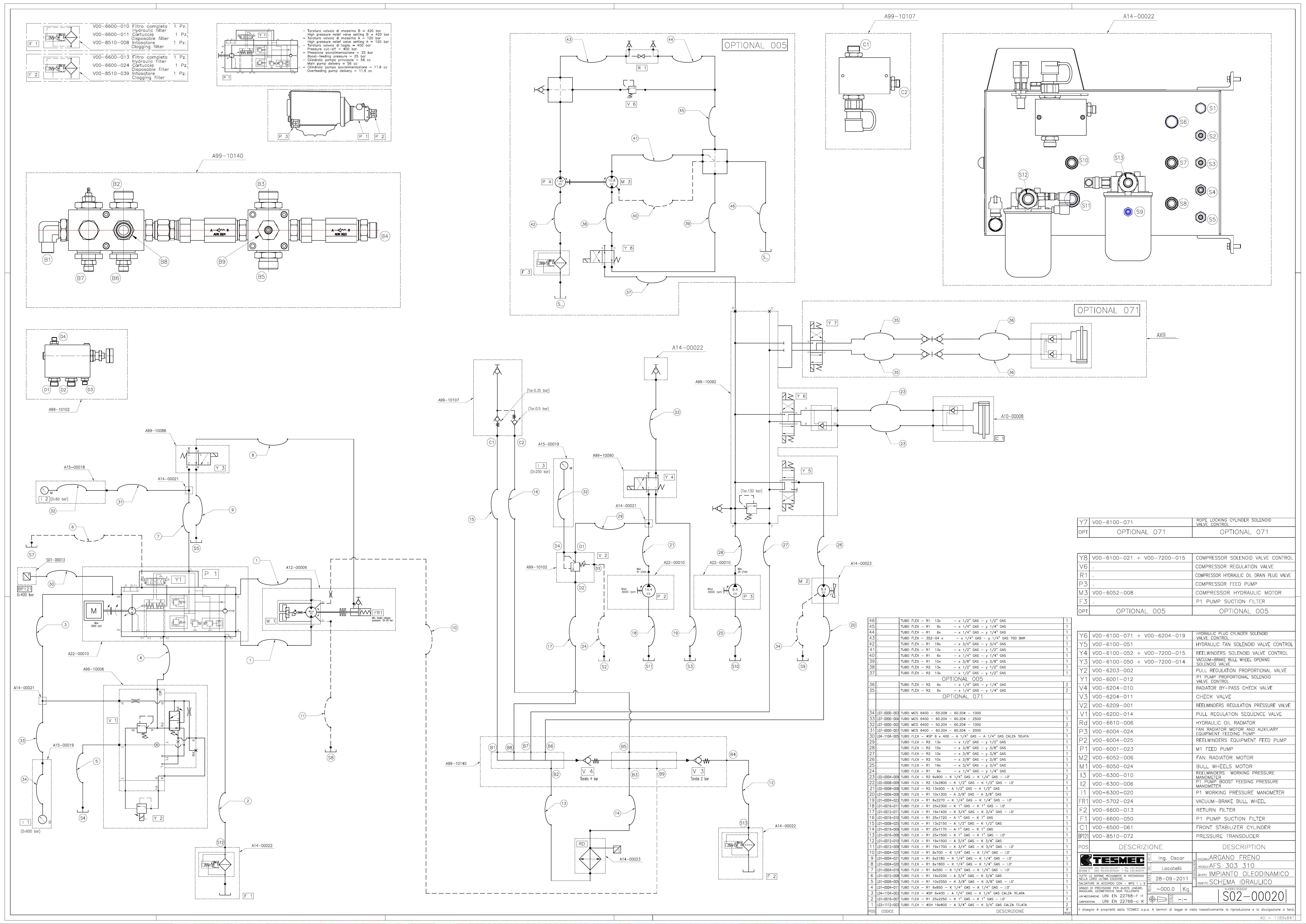
 Loading...