

Tesla G-TECH, RR Fanatic, Pro SS User Manual

Tesla Electronics Inc.
G-TECH/Pro SS/RR Fanatic
Manual
Detailed user manual – preliminary version
August 2011

Warning: Always obey all local and federal traffic laws when using this device.
Warning: Adverse weather conditions can severely impair given vehicles controllability, especially at high
speed. When using this device, drive cautiously and within the limits of your vehicle under the conditions.
Warning: Do not take your eyes of the road. This device is capable of recording any measurement and
replaying it later after the car has been stopped in a safe environment. This device is designed as a recording
instrument for a given vehicle. Use it for that purpose only.
TESLA Electronics Inc. or any of its subsidiaries shall not be held liable in any way for any accidental or
consequential damages to the vehicle, driver, passengers, and/or other involved parties or property occurring
while using G-TEC device.
TESLA Electronics Inc. reserves the right to make changes to this manual or other product specifications at any
time and without any further notice.
The content o this manual is for informational use only and is not intended as a commitment of any kind.
Please drive safely.
2 G-TECH/Pro SS/RR Fanatic Manual

Contents
1 Welcome ........................................................................................................................................................................... 5
1.1 Thank you ................................................................................................................................................................. 5
1.2 About your G-TECH ................................................................................................................................................... 5
2 Basics ................................................................................................................................................................................ 6
2.1 Front Side .................................................................................................................................................................. 6
2.2 Back Side ................................................................................................................................................................... 7
2.3 Accessories ............................................................................................................................................................... 7
2.4 Icons and Navigation ................................................................................................................................................ 7
3 Quick Setup ....................................................................................................................................................................... 9
3.1 Connecting ................................................................................................................................................................ 9
3.2 Adjusting Local Time ................................................................................................................................................. 9
3.3 Car Weight .............................................................................................................................................................. 10
3.4 Mounting System .................................................................................................................................................... 11
4 Everyday Driving ............................................................................................................................................................. 12
4.1 Main Screen Overview ............................................................................................................................................ 12
4.2 Mode....................................................................................................................................................................... 12
4.2.1 Mode Change .................................................................................................................................................. 13
4.3 Primary displayed measurement ............................................................................................................................ 13
4.4 Secondary displayed measurement ....................................................................................................................... 13
4.5 GPS Info .................................................................................................................................................................. 14
4.6 G-Arrow .................................................................................................................................................................. 14
4.7 SD card status ......................................................................................................................................................... 15
5 Performing SS Runs ......................................................................................................................................................... 15
5.1 SS Acceleration Run ................................................................................................................................................ 15
5.2 HP-TQ Measurement .............................................................................................................................................. 16
6 Recording RR Sessions .................................................................................................................................................... 18
6.1 RR Session Concepts ............................................................................................................................................... 18
6.1.1 Gates ............................................................................................................................................................... 18
6.1.2 Map ................................................................................................................................................................. 18
6.1.3 Map-Vicinity Automatic Recording ................................................................................................................. 18
6.1.4 The “Thumb” Screens ..................................................................................................................................... 19
6.2 RR Session – Circular Track ..................................................................................................................................... 19
6.2.1 Starting RR Session recoding .......................................................................................................................... 19
6.2.2 Driving on new location .................................................................................................................................. 20
6.2.3 Driving on prerecorded map with automatic recording enabled ................................................................... 25
6.2.4 Driving on prerecorded map with automatic recording disabled .................................................................. 26
6.3 RR Session – Hill-Climb ........................................................................................................................................... 27
6.3.1 Starting RR Session recoding .......................................................................................................................... 27
6.3.2 Driving on new location .................................................................................................................................. 27
6.3.3 Driving on prerecorded map with automatic recording enabled ................................................................... 27
6.3.4 Driving on prerecorded map with automatic recording disabled .................................................................. 27
3 G-TECH/Pro SS/RR Fanatic Manual

7 Reviewing Runs ............................................................................................................................................................... 28
7.1 Opening Saved Run ................................................................................................................................................. 28
7.1.1 From Internal Memory ................................................................................................................................... 28
7.1.2 From SD Card File System ............................................................................................................................... 29
7.2 SS Run Review ......................................................................................................................................................... 31
7.2.1 Speed graph .................................................................................................................................................... 32
7.2.2 Real-time replay .............................................................................................................................................. 33
7.2.3 Horsepower graph .......................................................................................................................................... 34
7.2.4 Braking distance graph ................................................................................................................................... 34
7.2.5 G-force graph .................................................................................................................................................. 35
7.2.6 Horsepower and Torque graph ...................................................................................................................... 36
7.3 RR Session Review .................................................................................................................................................. 37
7.4 Deleting a Run......................................................................................................................................................... 39
7.4.1 Deleting from internal memory ...................................................................................................................... 39
7.4.2 Deleting from SD Card File System ................................................................................................................. 40
7.5 Gates editing ........................................................................................................................................................... 43
7.6 Map rotation ........................................................................................................................................................... 44
7.7 Renaming the map.................................................................................................................................................. 45
8 Additional Features ........................................................................................................................................................ 46
8.1 Configuring Main Screen ........................................................................................................................................ 46
8.2 Changing Map-Vicinity Automatic Recording setting ............................................................................................. 47
8.3 Upgrading SS to RR ................................................................................................................................................. 47
8.4 Moving Runs To SD Card File System ..................................................................................................................... 48
8.5 HP Losses ................................................................................................................................................................ 48
8.5.1 Aerodynamic losses ........................................................................................................................................ 50
8.5.2 Drive train losses............................................................................................................................................. 50
8.6 Enabling/Disabling Key Click ................................................................................................................................... 51
8.7 LCD settings ............................................................................................................................................................ 51
8.7.1 Adjust color ..................................................................................................................................................... 52
8.7.2 Preset colors ................................................................................................................................................... 53
8.7.3 Adjust contrast................................................................................................................................................ 54
8.8 US or metric mode .................................................................................................................................................. 54
8.9 Reset options .......................................................................................................................................................... 55
8.9.1 Format SD Card ............................................................................................................................................... 55
8.9.2 Reset to factory defaults ................................................................................................................................ 56
9 Additional Info ................................................................................................................................................................ 58
9.1 About GPS ............................................................................................................................................................... 58
9.1.1 Update rate ..................................................................................................................................................... 58
9.1.2 Sensitivity ........................................................................................................................................................ 58
9.1.3 SBAS System ................................................................................................................................................... 58
9.2 About File System ................................................................................................................................................... 58
9.3 About Vehicle Weight ............................................................................................................................................. 59
10 Appendix A – Menu map ............................................................................................................................................ 60
4 G-TECH/Pro SS/RR Fanatic Manual

1 Welcome
1.1 Thank you
I would like to take this opportunity to thank you for being who you are. You, and guys like you, are keeping car
enthusiasm alive and well.
This new G-TECH/Pro Performance Meter is based on High-Speed 10Hz GPS technology and it’s better than ever. It’s
everything I always wanted it to be, so please enjoy it.
Jovo Majstorovic
President & CEO, TESLA Electronics Inc.
1.2 About your G-TECH
Your G-TECH is built for severe vibration environment, that’s why all of the components are “floating” inside rubber
material. There is no stress-points and hard mounts anywhere on the device. G-TECH has a built-in High-Frequency GPS
antenna (square bulge in the back) which needs to be exposed to the sky. When the unit is turned on you will see the
amount of satellites currently in the view (12 maximum) in the upper right corner of the display. The more satellites GTECH “sees” the higher the accuracy will be. When you turn on the G-TECH it will take a few minutes to lock onto the
satellites. Look for a small plus sign between the satellite icon and the number of satellites. This indicates that SBAS
(Satellite Based Augmentation System) is locked in, this will improve accuracy. For best performance, keep the G-TECH
right on top of the dash in the bottom of the windshield. Small icon on top of the screen indicates if the MicroSD card was
inserted properly (RR model).
There are two models, SS (Super Sport) and RR (Road Racer). To upgrade from SS to RR is as simple as inserting a RR
expansion board in the back of the unit. Available at gtechpro.com
SS is intended for all of the standard straight-line performance measurements including, Horsepower, Torque, 0-60mph,
60ft times, 1/8 mile, 1/4 mile, braking distance and more. It has the capability to replay runs and can be used in all
vehicles including cars, motorcycles, boats, tanks etc.
RR model has all of the functions of the SS plus it has the ability to record lap times on the racetrack. RR is also capable of
displaying lap-segment times as you are driving. This feature will help you improve as a driver and help shave-off seconds
from your lap times.
5 G-TECH/Pro SS/RR Fanatic Manual
2 Basics
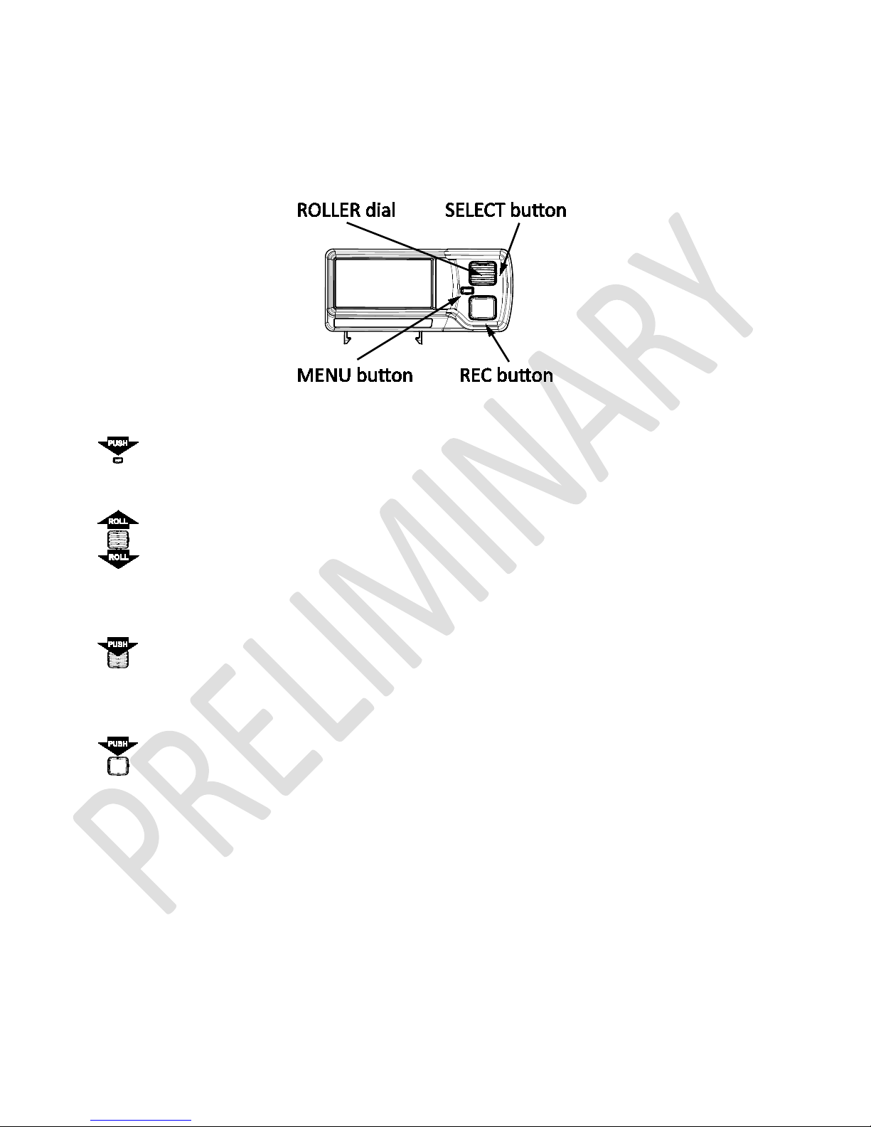
2.1 Front Side
Figure 1: G-TECH front side
•
MENU button – used to get you in and out of main menu and out of submenus
•
ROLLER dial – is the most important in navigating though the user interface. Please note that besides being able
to rotate up and down, it can also be pushed-in to select a given menu item.
•
SELECT button – is the part of the ROLLER dial. You can push-in the ROLLER dial and this action will be referred to
as SELECT button throughout this manual.
•
REC button – this is the record/replay button and it its used to let G-TECH know that you want to start a SS run or
a RR session recording. It’s also used to input Start/Finish line and segment gates in RR mode. Throughout this
manual, this button will be referred to simply as REC button.
6 G-TECH/Pro SS/RR Fanatic Manual
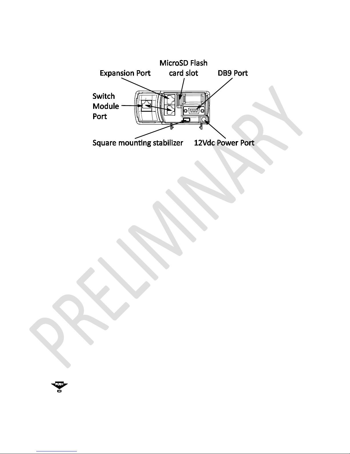
2.2 Back Side
Figure 2: G-TECH back side
• 12Vdc Power Port – plug in the supplied DC power cable into this connector
• Expansion Port – reserved for future use
• Switch Module Port – connect Switch Module to this port using supplied Ethernet cable
• DB9 Port – no user functions are available trough this port, used in G-TECH production and maintenance only
• MicroSD FLASH Card Slot – It uses “push in & push out” action just like a ball-point pen. Pushing it with a paper-
clip works well
• Square mounting stabilizer – Insert this stabilizer into the square hole in the mounting clip and snap it.
2.3 Accessories
• 12V cigarette lighter DC Power Cable – supplies power from vehicle’s accessory (cigarette lighter) plug.
The DC Power Plug has a fuse at the end that plugs into your vehicle. If the cable does not seem to provide
power, the fuse may be blown and need replacing.
To replace the fuse, unscrew the tip and replace the fuse with a standard 1A (one ampere) fuse. Fuses can
normally be purchased at any automotive parts store.
• Mounting System – used to hold your G-TECH steady in you vehicle.
For additional details, please refer to “Mounting System” on page 11.
2.4 Icons and Navigation
The G-TECH’s functionality is accessible trough its user-friendly icon interface.
Pressing the MENU button on the Main Screen brings up the main menu, as shown below:
7 G-TECH/Pro SS/RR Fanatic Manual
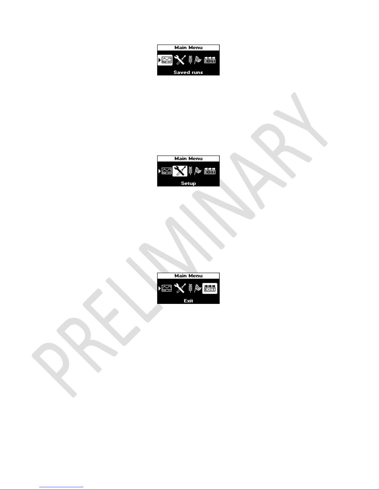
Figure 3: The G-TECH's Main Menu
The name of the menu appears in the Menu Title Bar at the top of the display (“Main Menu” in this example).
The main menu has 4 icons. The first icon is in “reverse video” because it is the active (selected) icon. Use the ROLL dial to
move amongst the different icons.
For example, moving the ROLL dial down by “one click” in Figure 3 would move the icon selection to the Setup icon, as
shown below:
Figure 4: Main Menu: "Setup" icon selected
The Setup Icon Hint in Figure 4 indicates that the selected icon represents setup items.
Use the SELECT button to make a selection. For example, to customize the G-TECH you would move to Setup icon and
then press SELECT button.
Selecting Exit icon on any menu brings you up one level. If you are on the Main Menu when you select Exit, you will be
returned to the Main Screen.
Figure 5: Main Menu: "Exit" icon selected
Moving one level up on any menu can also be accomplished by pressing MENU button. If you are on the Main Menu
when you press MENU button, you will be returned to the Main Screen. Pressing MENU button again while on Main
Screen will bring you back to Main Menu.
8 G-TECH/Pro SS/RR Fanatic Manual
3 Quick Setup
3.1 Connecting
There are only two cables to connect on the G-TECH unit. The Switch Module is connected to Switch Module Port by
supplied short Ethernet cable. If you want to mount the Switch Module away from G-TECH unit you can use longer
straight-trough Ethernet cable to do that. Power supply is connected trough 12VDC Power Port.
For location of Switch Module Port and 12VDC Power Port, please see the image in section 2.2 on page 7.
3.2 Adjusting Local Time
G-TECH date and time are based on Coordinated Universal Time (UTC) which is extracted from GPS signal. This time code
is closely related to Greenwich Mean Time (GMT) and it has time zones defined the same way as GMT. To obtain correct
date and time you need to adjust difference between UTC and your local time.
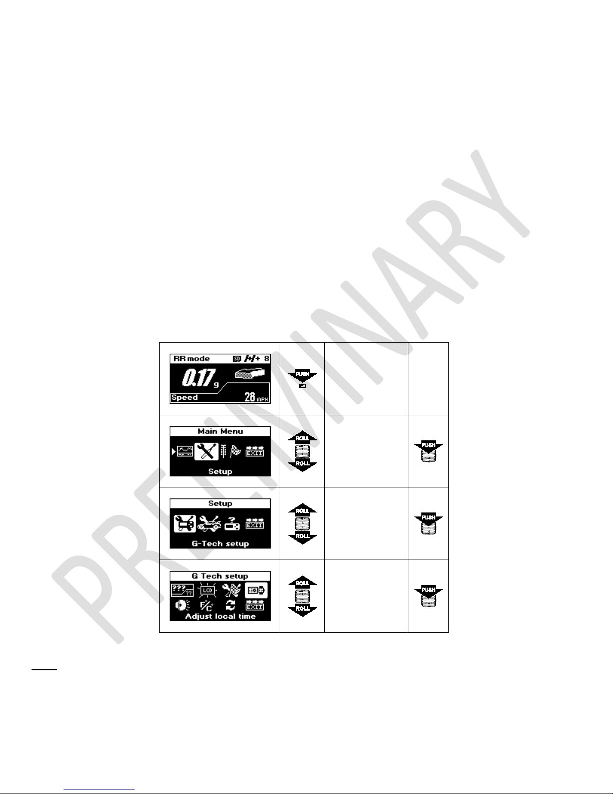
To access Adjust local time menu, follow the steps below:
Press MENU
button to enter
Main Menu
Select
Setup
Select
G-Tech Setup
Select
Adjust local
time
Note:
This setup requires that G-TECH has a valid GPS signal in order to extract UTC date and time. If that is not the case,
you will see a screen as shown below:
9 G-TECH/Pro SS/RR Fanatic Manual
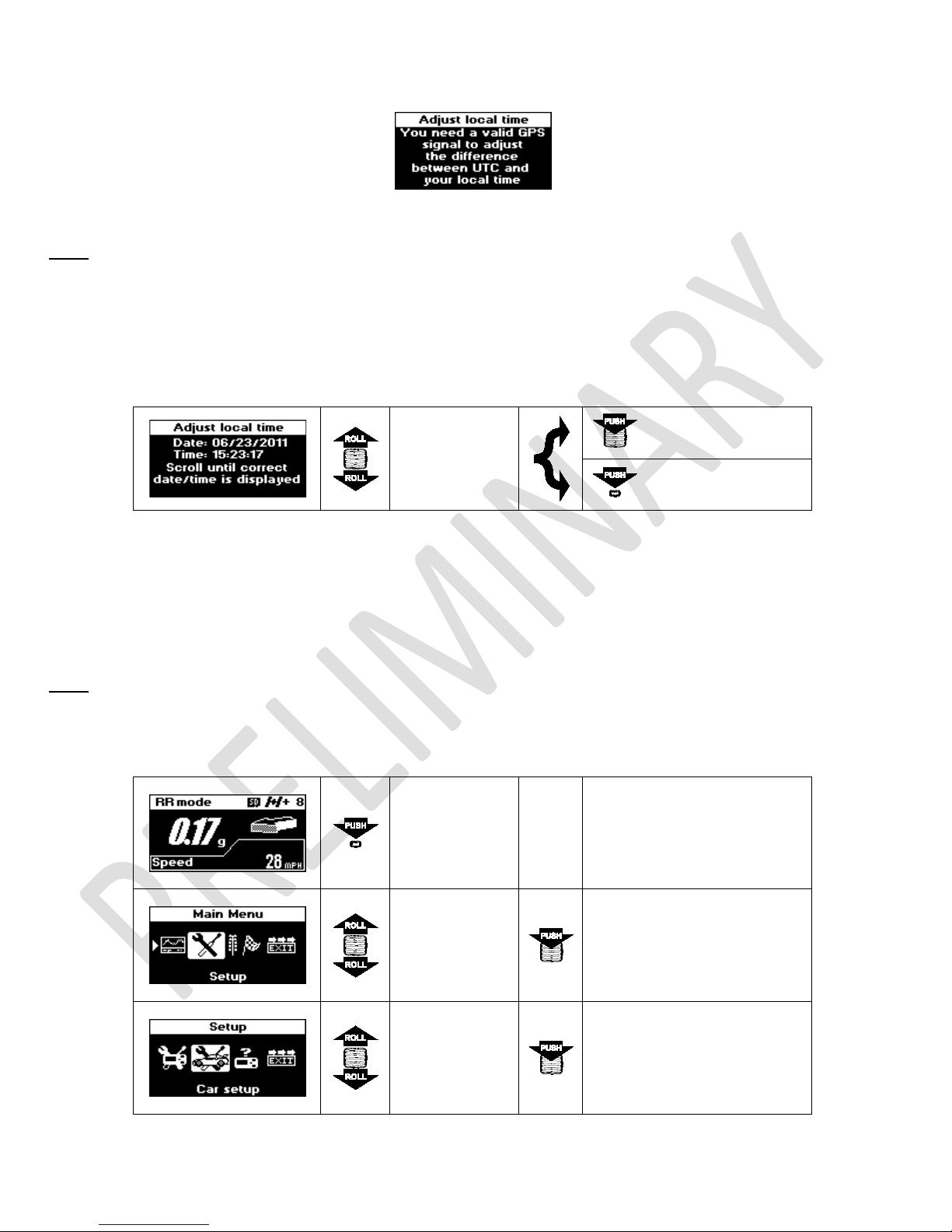
Figure 6: Adjust local time - no valid GPS signal
Note: You need to be in open space for G-TECH to acquire valid GPS signal. If you are in garage, under the large bridge
or in a tunnel, please drive your car out into open.
Once G-TECH has a valid GPS signal you will be presented with this screen, where you can use ROLL button to change
displayed time until it mach your local time.
Roll up or down
to adjust time
Confirm selection
displayed on
the screen
Cancel changes
You can adjust only hour portion of the time which corresponds to your local time zone. UTC time is extremely accurate
and it’s minutes and seconds portions are guaranteed to be correct, therefore they can’t be changed.
3.3 Car Weight
Note: Vehicle weight must be set properly in order to obtain accurate HP measurements. For help determining vehicle
weight, please see page 59 for details.
Press MENU
button to enter
Main Menu
10 G-TECH/Pro SS/RR Fanatic Manual
Select
Setup
Select
Car setup
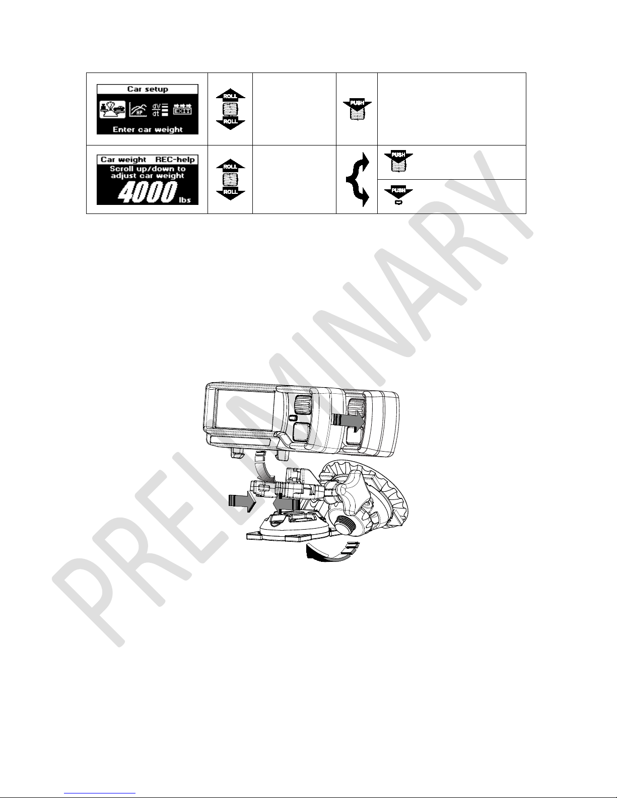
Select
Enter Car
weight
Roll to adjust
Confirm selection
car weight
Cancel changes
3.4 Mounting System
To mount the G-TECH in the clip, insert the square mounting stabilizer at the back of the G-TECH into the square hole in
the clip and snap it. To remove it, squeeze the handles and pull it out. See illustration below for details.
Switch module can be detached from G-TECH body by pushing it backward. This way you can mount it somewhere closer
to you. You will find this very useful especially when strapped in a 5-point racing harness. It uses a regular Ethernet
straight-trough (network) cable which can be purchased in any electronics store.
G-TECH can be mounted on the windshield with the suction cup or any other surface, including the dashboard by using
the three mounting screw holes or a 2” square piece of Velcro.
11 G-TECH/Pro SS/RR Fanatic Manual
4 Everyday Driving
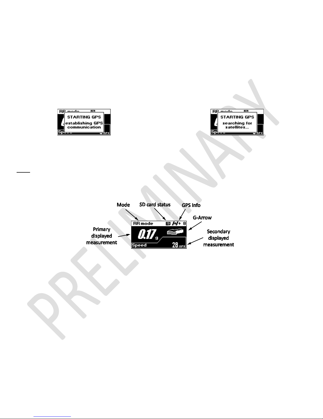
4.1 Main Screen Overview
After power-on, the G-TECH starts GPS communication (Figure 7) followed by searching for satellites (Figure 8). Until it
acquires valid GPS signal, G-TECH will keep this message on.
Figure 7: Starting GPS: establishing GPS communication
Figure 8: Starting GPS: searching for satellites...
Note:
You need to be in open space for G-TECH to acquire valid GPS signal. If you are in garage, under the large bridge
or in a tunnel, please drive your car out into open.
After acquiring valid GPS signal, G-TECH will hide “STARTING GPS” message and you will be presented with Main Screen
Figure 9: G-TECH's Main Screen
The Main Screen in Figure 9 has six main indicators:
• Mode – shows current mode of operation
• Primary displayed measurement – shows selected measurement in big numbers
• Secondary displayed measurement – shows selected measurement in smaller numbers
• G-Arrow – direction of G-Force
• GPS Info – basic information of current GPS status
• SD card status – indicates whether SD card file system is available
4.2 Mode
G-TECH Fanatic series devices come in two versions, SS and RR. The G-TECH SS Fanatic has one mode of operation, the
“SS mode” which will always be indicated on the Main Screen. If you purchased G-TECH RR Fanatic, or upgraded your G-
12 G-TECH/Pro SS/RR Fanatic Manual
TECH SS Fanatic with SS to RR Upgrade Kit, you will be able to choose operating mode. In this case G-TECH will indicate
current mode by showing “SS mode” or “RR mode”.
For additional details about SS and RR modes, please see page 15 or page 18 respectively.
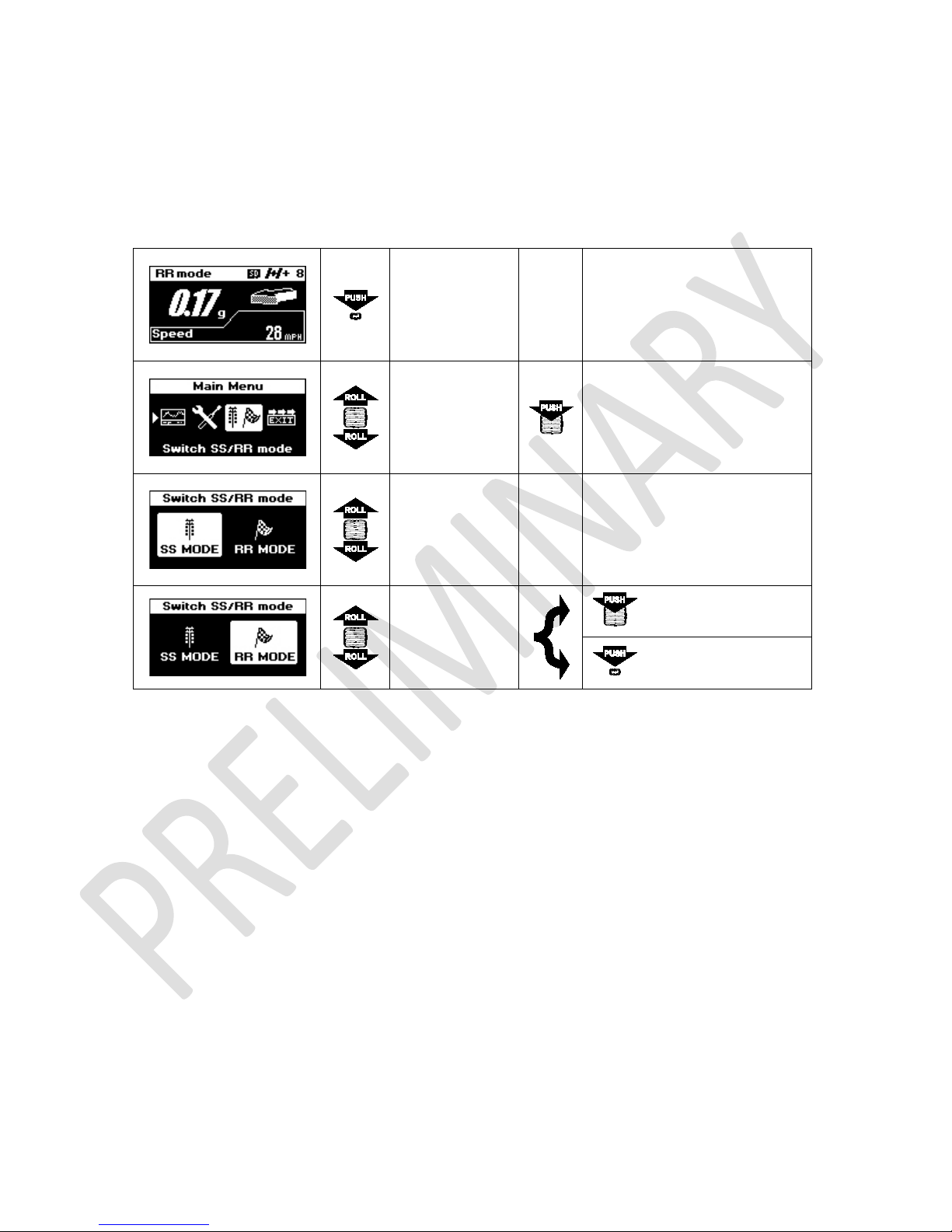
4.2.1 Mode Change
Press MENU
button to enter
Main Menu
Select
Switch SS/RR
mode
Roll up or down
to select mode
Roll up or down
to select mode
Confirm selection
Cancel changes
4.3 Primary displayed measurement
By default, primary displayed measurement indicates amount of G-force. In combination with G-Arrow it creates a Realtime G meter. Primary displayed measurement can be configured to show any of these 3 parameters: G-force, speed or
real time horsepower.
Please see page 46 for details on configuring Main Screen.
4.4 Secondary displayed measurement
By default, secondary displayed measurement indicates current speed. It can be configured to show any of these 3
parameters: Speed, G-force or real time horsepower.
Please see page 46 for details on configuring Main Screen.
13 G-TECH/Pro SS/RR Fanatic Manual
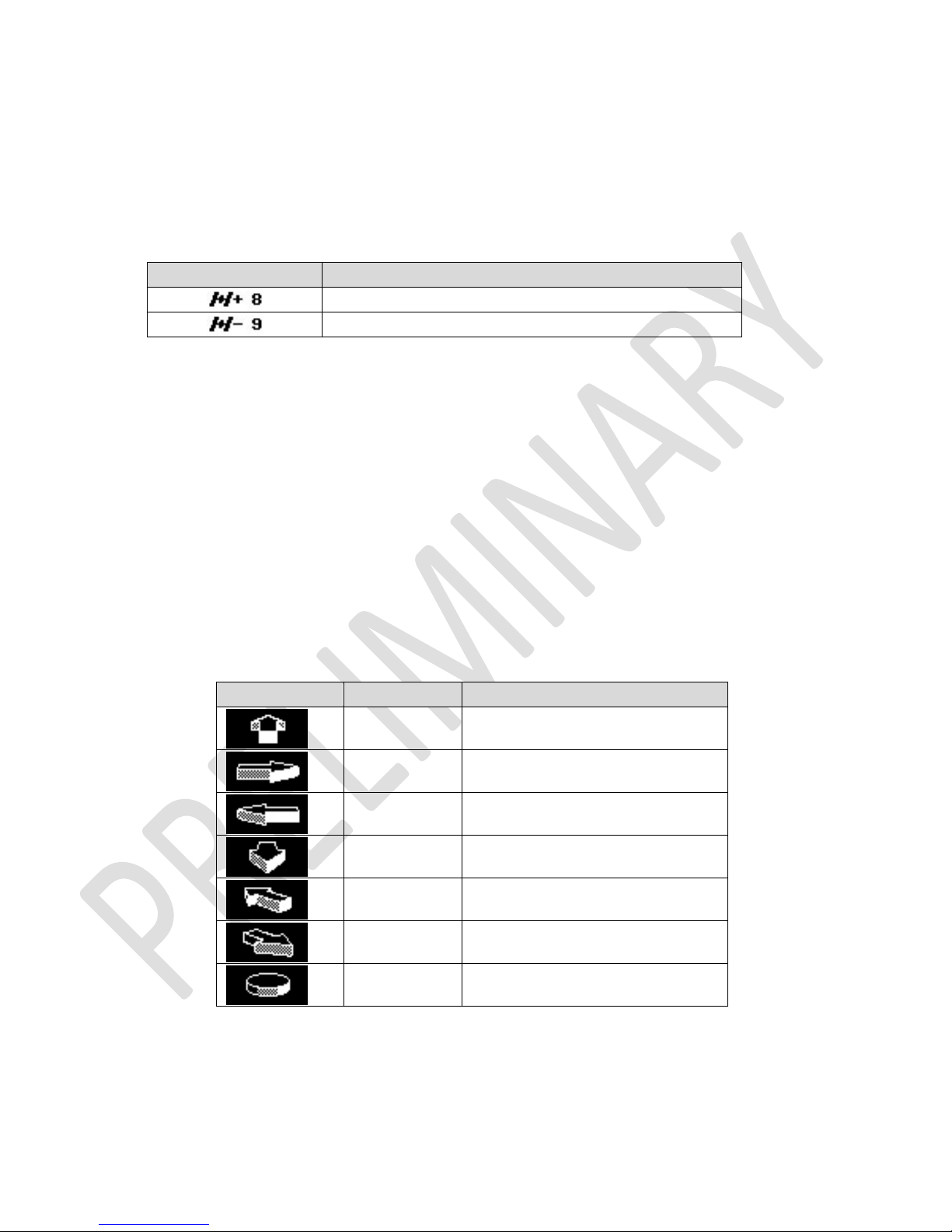
GPS Info
Condition
Eight satellites being tracked, SBAS available
G-Arrow
G-Value
Condition
.85
Accelerating Fwd 0.85 Gs
.34
Left Turn 0.34 Gs
.28
Left Turn & Accelerating 0.28 Gs
.00
Minimal G-force
4.5 GPS Info
GPS info indicator consists of satellite icon followed by SBAS indicator and number of satellites being tracked.
G-TECH’s GPS receiver is SBAS enabled, meaning that it can provide improved performance trough integration of
external information when available. If SBAS is available, satellite icon is followed by “+” sign, otherwise by “-“ sign.
Nine satellites being tracked, SBAS unavailable
Please see page 58 for more information on SBAS.
4.6 G-Arrow
The Real-time G Meter is a combination of the G-Value and the G-Arrow. It indicates both the amount and direction of Gforce, whether your vehicle is braking, cornering, or blasting down the dragstrip.
The display is continuously updated in response to your driving, and tells you all you need to know about your vehicle’s
handling and acceleration capabilities.
The G-value indicates the amount of G-force to within a one hundredth of a G. G-Arrow indicates the direction of G-force.
Figure 10 illustrates how to read the Real-time G Meter.
Right Turn 0.75 Gs
.75
1.55
Braking 1.55 Gs
.56
Right Turn while Braking 0.56 Gs
14 G-TECH/Pro SS/RR Fanatic Manual
Figure 10: Real-time G Meter examples
4.7 SD card status
This indicator is available only on G-TECH RR Fanatic which uses SD file system for data storage.
Display of SD card icon indicates that card is present and file system is operational.
5 Performing SS Runs
Note: G-TECH must be in SS mode to perform SS Run. For information on how to change current mode, please see page
13.
There are two types of measurements possible in SS mode, the SS Acceleration Run and HP-TQ Measurement. They
require different driving techniques so please be sure to read and understand following instructions.
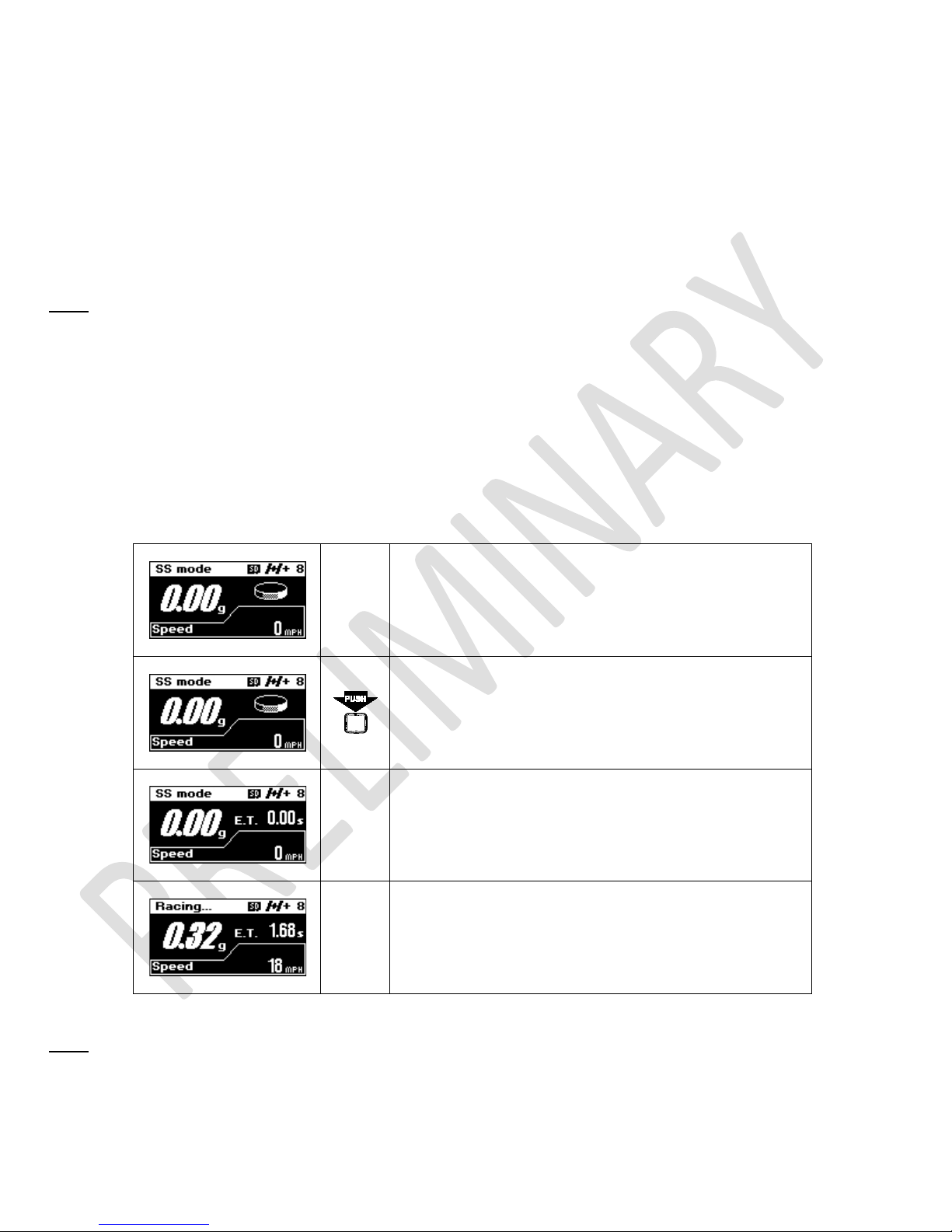
5.1 SS Acceleration Run
This section describes how to measure accelerating and braking performance. With G-TECH Fanatic series this type of
measurement can be made either from stop or while car is already running.
Make sure G-TECH is mounted properly, powered on, in
SS mode, GPS has a valid signal, and Main Screen is
displayed
Press REC button to activate recording
Accelerate you vehicle briskly and G-TECH will
automatically start recording. Note that E.T. clock will
start running.
Keep driving…
Note: The G-TECH requires some “oomph” to automatically start recording. If G-TECH doesn’t start timing, launch your
car with more force. G-TECH will reduce the amount of force required if you’re not starting from stop.
15 G-TECH/Pro SS/RR Fanatic Manual
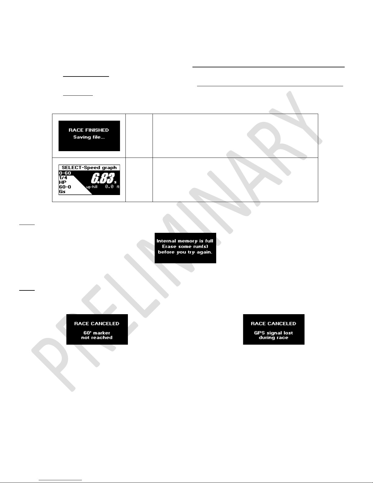
To finish the run:
• if you want to measure braking distance, brake strongly all the way to a complete stop, and wait for the
• if you do not care about braking distance, simply let off throttle and coast for about 1 second, until E.T.
• press REC or MENU button to cancel the race
E.T. clock to stop
clock stops
The run will be saved automatically. While the run is
being saved, the display will show “RACE FINISHED”
screen as shown here.
After saving the run, G-TECH will open it for review as
show bellow. For information on how to view and analyze
your runs, please see page 31.
Note:
If you don’t have enough free storage in internal memory, you will not be able to start the SS Run.
Figure 11: Internal memory is full
Note: If you do not travel at least 60 ft, or you loose GPS signal while recording, the run will be discarded.
Figure 12: Race too short
Figure 13: GPS lost
5.2 HP-TQ Measurement
This type of measurement requires different driving technique. For best results make sure you follow the instructions
from G-TECH.
16 G-TECH/Pro SS/RR Fanatic Manual
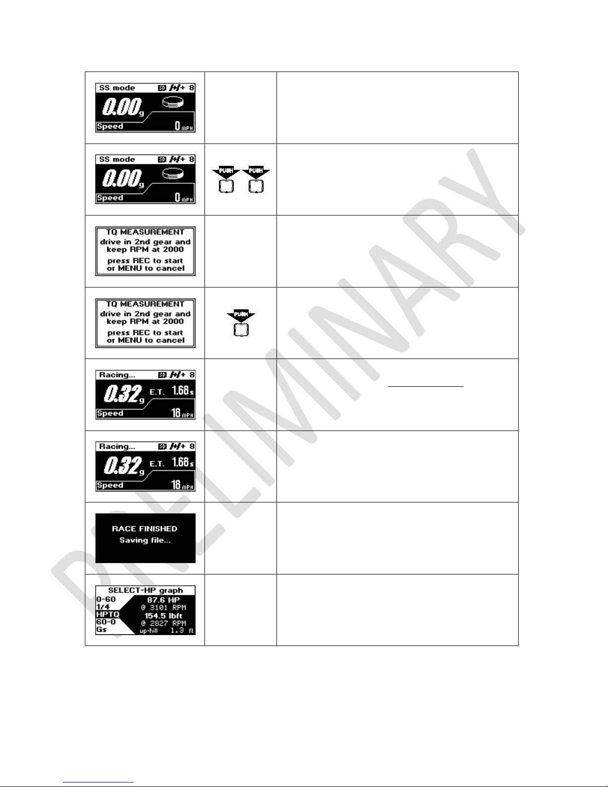
Make sure G-TECH is mounted properly, powered
on, in SS mode, GPS has a valid signal, and Main
Screen is displayed
Double-click REC button to activate recording
Start your vehicle and keep driving according to
nd
instructions. Drive in 2
at 2000 RPM.
gear and keep your engine
When you have reached 2000 RPM, press REC
button to start recording.
Step on the accelerator all the way down. Keep
driving like that until you reach redline with engine
RPMs.
If you reached redline, let the throttle off and coast
for about 1 second, until E.T. clock stops.
The run will be saved automatically. While the run
is being saved, the display will show “RACE
FINISHED” screen
17 G-TECH/Pro SS/RR Fanatic Manual
After saving the run, G-TECH will open it for review.
For information on how to view and analyze your
runs, please see page 31.

6 Recording RR Sessions
Note: G-TECH must be in RR mode to record RR Session. For information on how to change current mode, please see
page
13.
In RR mode you can record your racing session on circular or hill-climb tracks. During the session G-TECH records your
vehicle’s position, speed, acceleration and lap times all in real time as you go.
6.1 RR Session Concepts
6.1.1 Gates
When thinking about gates, first thing you should think of is a START/FINISH line on a circular track. This line is defined by
two points, one on the leftmost side of the track and other on the rightmost side. During the race you are crossing the
START/FINISH line only in one direction. This means that START/FINISH line is orientated is in driving direction.
G-TECH specifies gates the same way. They have a direction and they are defined by two points on a map. Only difference
is that defining points usually lay outside the track, the gate is normally wider than track.
There are also two types of gates. The START/STOP gates are special because they define the start and end of the track.
On circular tracks, this is the same line. On hill-climb track these are two different gates.
Other type of gate is a segment gate, it is used to mark positions on track and divide track into segments. This way you
can measure segment times, cornering times, etc.
The START/STOP gates are defined during map recording and they can not be changed or moved. The segment gates can
be defined during map recording or you can add/remove them later when reviewing the session.
On how to change segment gates after the session, please see page 43.
6.1.2 Map
G-TECH maps are defined by START/STOP gate, optional segment gates and GPS location points representing the race
track shape. Each map has a name and default viewing orientation.
All RR Sessions are driven on maps which can be recorded during the race or reused from some previous session.
6.1.3 Map-Vicinity Automatic Recording
While in RR mode, G-TECH is constantly tracking distances to existing maps. When you approach the location of existing
map G-TECH will detect that situation and load the map in preparation for RR Session recording. If multiple maps are
found in your vicinity you will be asked to select which map you will be driving at.
With Map-Vicinity Automatic Recording you can start RR Session recording without even having to press one button. Just
drive your vehicle to the track, go over the START line and that’s it!
G-TECH will load the map as you approach the track and start recording when you cross the START line.
18 G-TECH/Pro SS/RR Fanatic Manual
 Loading...