

Page 1

Owners Manual
Page 2

score
score
Spine: 15/32” wide
Page 3

A WORD TO ROADSTER OWNERS
Thank you for choosing a Tesla Roadster. Not only have you chosen one of the finest sports cars on the road, you have also
chosen the most energy efficient sports car ever sold. You are participating in a revolution, demonstrating that kicking the oil
habit does not mean you have to give up performance and driving pleasure.
Take the time to get well acquainted with your Tesla Roadster by reading this manual. The more you know and understand
your vehicle, the more safety and pleasure you’ll experience driving it.
Tesla Motors knows your Roadster best. So when service or maintenance is required, Tesla Motors is the place to go. Visit us
regularly at www.teslamotors.com for more information about your Tesla Roadster. By signing into the owners area of this web
site, you can access all the information you need about your specific vehicle, including service information.
Enjoy your Tesla Roadster!
Tesla Motors
San Carlos, California, USA
Page 4

Table of Contents
For information on how to use the Touch Screen and how to charge your vehicle, refer to the separate manuals
provided in your owners package. For information on how to use the audio and navigation system, refer to the
Original Equipment Manufacturer (OEM) documentation provided by Tesla Motors.
Introduction and consumer information
Important notes about your vehicle 1-2
Important notes about this manual 1-3
Consumer information 1-5
Your vehicle at a glance
Exterior 2-2
Interior 2-4
Seating and safety restraints
Seats 3-2
Seat belts 3-3
Airbag system 3-6
Doors, locks, and security
Keys 4-2
Doors 4-4
Trunk 4-6
Vehicle security 4-7
Charging your vehicle
General information about charging 5-2
Charge settings 5-4
Charging components 5-6
Driving your vehicle
Driving basics 6-2
Switches and controls 6-6
Instruments 6-11
Comfort and convenience
Power windows 7-2
Rear view mirrors 7-3
Interior temperature control 7-4
Interior accessories 7-6
Removable roof 7-8
HomeLink® 7-14
Maintenance and care
Maintenance 8-2
Fluid reservoirs 8-5
Windshield wiper and washer 8-7
Cleaning and vehicle care 8-8
Roadside emergencies
Tool kit 9-2
Energy Depletion 9-3
Tire repair 9-4
Wheels 9-6
Fuse replacement 9-7
Bulb replacement 9-9
Raising the vehicle 9-11
Vehicle recovery 9-13
Technical specifications
Vehicle identification 10-2
Wheels and tires 10-4
Approved fluids and capacities 10-14
Vehicle dimensions and weights 10-15
Subsystem specifications 10-17
Page 5

1-1
Introduction & consumer information
Important notes about your vehicle
Electric vehicle precautions 1-2
California Proposition 65 1-2
Vehicle modifications 1-2
Service data recording 1-2
Change of address or ownership 1-2
Important notes about this manual
Read this manual first 1-3
Copyright and trademarks 1-3
Symbols glossary 1-4
Consumer information
Reporting safety defects 1-5
Page 6

Important notes about your vehicle
1-2 Introduction and consumer information
Introduction and consumer informationImportant notes abo ut your vehicle
Electric vehicle precautions
WARN ING: HIGH VOLTAGE. The Tesla
Roadster
TM
has both AC and DC high
voltage systems in addition to a normal 12V
DC system. High voltage is very dangerous
and can cause personal injury including
electric shock, severe burns and even fatal
injury. Always observe and obey the
instructions on all labels attached to
components on your vehicle - they are there
for your safety. Do not touch, remove or
replace any high voltage parts. If your vehicle
is involved in an accident, do not touch any
high voltage wiring (identified by the orange
outer sleeving), the connectors or the
components connected to the wiring.
S
California Proposition 65
WARNING: Certain vehicle components
contain or emit chemicals known to the
State of California to cause cancer and birth
defects or other reproductive harm. In
addition, certain fluids contained in vehicles
and certain products of component wear
contain or emit chemicals known to the State
of California to cause cancer and birth
defects or other reproductive harm.
S
WARNING: Certain components of this
vehicle such as airbag modules and
seat belt pretensioners may contain
Perchlorate Material. Special handling may be
required for service or vehicle end of life
disposal. See http://www.dtsc.ca.gov/
hazardouswaste/perchlorate.
S
WARNING: Battery posts, terminals,
and related accessories contain lead
and lead compounds. Wash hands after
handling.
S
Vehicle modifications
WARNING: The fitting of non-approved
parts and accessories, or the
implementation of non-approved
modifications to any vehicle components,
including any “hacking” of the vehicle’s
software, may be dangerous and could affect
the safety of your vehicle and its occupants
and also invalidate the terms and conditions
of the New Vehicle Limited Warranty.
S
WARN IN G : Te sl a Mo tor sTM will not
accept any liability for death, personal
injury or damage to property which may
occur as a direct or indirect result of
non-approved modifications or the fitment of
non-approved accessories.
S
If you have a disability which requires
modification to your vehicle, consult Tesla
Motors before making these modifications.
Service data recording
Service data recorders in your vehicle are
capable of collecting and storing diagnostic
information about your vehicle. This
potentially includes information about the
performance or status of various systems and
control modules in your vehicle such as
motor, accelerator, or brakes. To properly
diagnose and service your vehicle, Tesla
Motors and service facilities may access
vehicle diagnostic information through a
direct connection to your vehicle.
Change of address or
ownership
If you change your address, it is in your best
interest to notify Tesla Motors so we can
contact you should the need arise. Send in
the “Change of Address Notice” found in the
New Vehicle Limited Warranty” booklet, or
simply call Tesla Motors.
If you sell your vehicle, leave all original
owners package materials in the vehicle to
make it available for the next owner.
If you bought this vehicle used, either fill in
the “Change of Address Notice” found in the
New Vehicle Limited Warranty booklet, or
simply call Tesla Motors.
Page 7

Important notes about this manual
1-3Introduction and consumer information
Important notes ab out this manual
Read this manual first
This owners manual contains a great deal of
information you need to know about a Tesla
Roadster. We urge you to read it carefully and
familiarize yourself with the vehicle before
driving.
For your own safety, follow the instructions
and warnings contained in this manual.
Ignoring them could result in damage to the
vehicle or personal injury to you or others.
Vehicle damage caused by failure to follow
instructions is not covered by the New
Vehicle Lim ited Warranty.
Keep this manual in your Roadster as a
reference for the safe and enjoyable use of
your Tesla Roadster. Should you sell your
vehicle, be sure to provide this manual to the
new owner.
All specifications and descriptions are
accurate at the time of printing. Because
improvement is a constant goal at Tesla
Motors, we reserve the right to make changes
at any time, without notice and without
obligation.
This manual applies to all Roadster 2 and
Roadster Sport vehicles. As a result, you may
find some explanations for equipment or
options not installed on your vehicle. When
required, Tesla Motors distributes an
addendum to provide updated information.
An effective way to find the information you
need is to use the index at the back of this
manual. If you are unable to find the
information you need, note that the following
additional documents are included in your
owners package:
• Audio and Navigation Guides - describes
how to use the audio/navigation system
• Quick Reference - a summarized version
of the information contained in all
manuals to help you quickly understand
your vehicle and its features
• Touch Screen Users Manual - describes
how to use the screens to display
important information while parking,
driving, and charging the vehicle
• Charging Your Vehicle - describes how to
charge your vehicle
• Roadside Assistance Guide - describes
the Tesla Motors Roadside Assistance
program and provides instructions on
how to transport the vehicle
• Warranty Booklet - details the New
Veh ic le Li mi te d Wa rran ty
• Tire Warranty - details the warranty for
the vehicle’s tires
In addition to the documents in your owners
package, Tesla provides the following
documents:
• High Power Connector Installation
Manual - provides planning guidelines for
the installation of the High Power
Connector as well as step-by-step
installation instructions. This manual is
included with the delivery of the High
Power Connector.
• Mobile Connector Users Manual describes how to the use a Tesla Motors
mobile connector. This manual is included
with the deliery of a Tesla Motors mobile
connector.
• OEM Audio & Navigation System manual
- describes how to use the vehicle’s audio
and navigation system. This manual is
provided in your vehicle’s trunk.
When required, Tesla Motors may also include
an addendum in the owners package if your
vehicle differs from what is in the manuals. If
you are missing a document, contact Tesla
Motors.
Copyright and trademarks
©2009 TESLA MOTORS INC. All rights
reserved. This material may not be
reproduced or copied, in whole or in part,
without the written permission of Tesla
Motors, Inc.
“Tesla Motors
TM
” and “Tesla RoadsterTM” are
trademarks of Tesla Motors, Inc. “HomeLink®”
is a registered trademark of Johnson
Controls, Inc. iPod® is a registered trademark
of Apple Computer, Inc. Havoline® is a
registered trademark of Chevron or its
affiliates. TORX® is a registered trademark of
Textron, Inc. All other trademarks are the
property of their respective owners.
Page 8

Important notes about this manual
1-4 Introduction and consumer information
Symbols glossary
The following symbols used within this
manual call your attention to specific types of
information:
WARNING: Indicates a situation in
which serious bodily injury or death
could result if the warning is ignored.
S
Caution: Indicates a situation in which
bodily injury or damage to your vehicle,
or both, could result if the caution is ignored.
Identifies items that must be disposed
of safely to prevent unnecessary
damage to the environment.
Note: A note provides useful supporting
information and sometimes suggests how to
make better use of your vehicle.
Page 9

Consumer information
1-5Introduction and consumer information
Consumer information
Reporting safety defects
United States
If you believe that your vehicle has a defect
which could cause a crash or could cause
injury or death, you should immediately
inform the National Highway Traffic Safety
Administration (NHTSA) in addition to
notifying Tesla Motors.
If NHTSA receives similar complaints, it may
open an investigation, and if it finds that a
safety defect exists in a group of vehicles, it
may order a recall and remedy campaign.
However, NHTSA cannot become involved in
individual complaints between you and
another party such as Tesla Motors.
To contact NHTSA, call the Auto Safety
Hotline toll-free at 1-888-327-4236 (TTY:
1-800-424-9153); go to
http://www.safercar.gov
; or write to:
Administrator, NHTSA
1200 New Jersey Avenue SE
Was hington, D C 2 0590
You can also obtain other information about
motor vehicle safety from
http://www.safercar.gov
.
Canada
If you believe that your vehicle has a defect
which could cause a crash or could cause
injury or death, you should immediately
inform Transport Canada, in addition to
notifying Tesla Motors.
To contact Transport Canada, call their
toll-free number: 1-800-333-0510.
Page 10

2-1
Your vehicle at a glance
Exterior
Exterior overview 2-3
Interior
Dashboard overview 2-5
Page 11
Exterior
2-2 Your vehicle at a glance
Your vehicle at a glance
10TR0109
1 2
6543
7
8
10
9
Page 12

Exterior
2-3Your vehicle at a glance
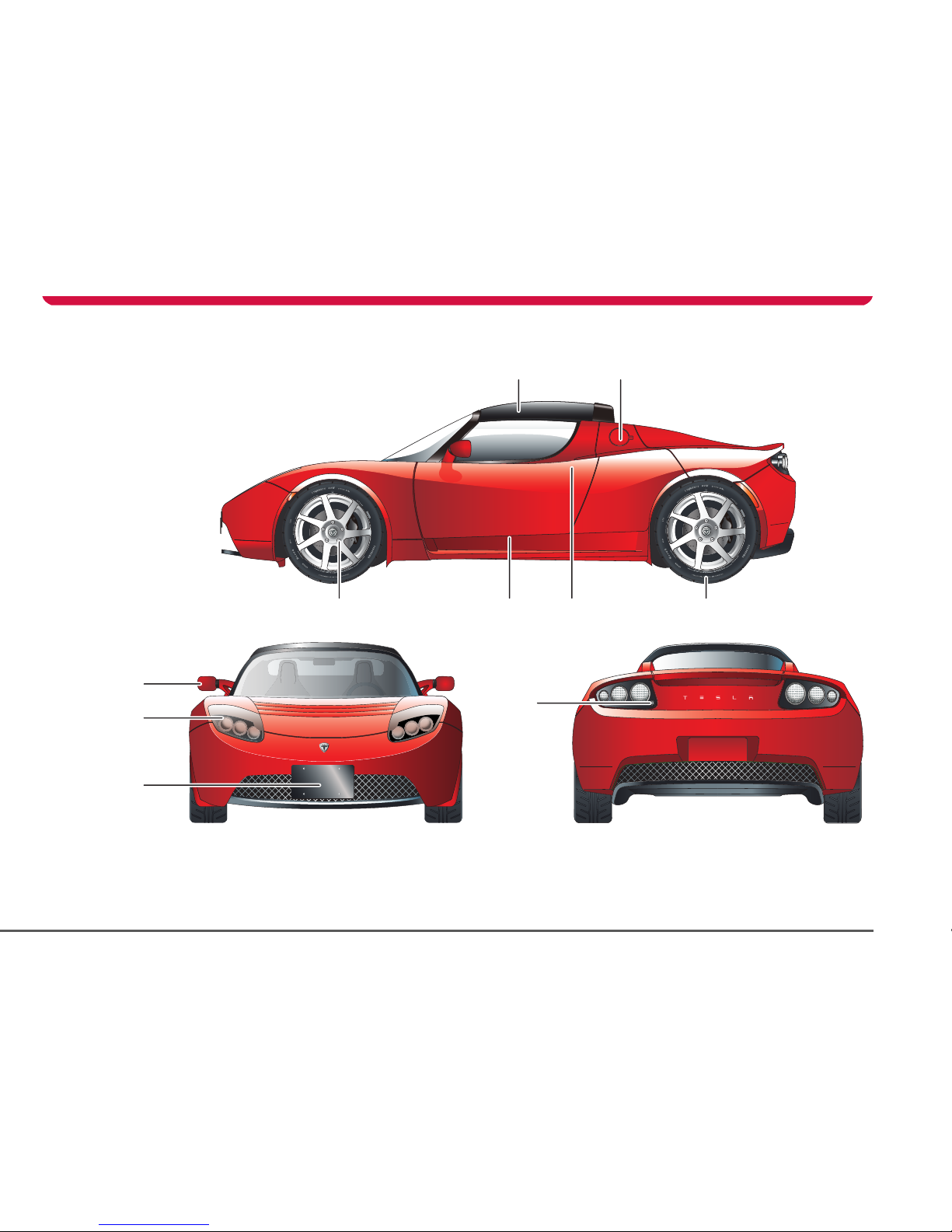
Exterior overview
1. Roof. See Removable roof, page 7-8.
2. Charging port door. For details on vehicle charging, see the manual titled “Charging Your Vehicle” provided in your owners package.
3. Wheel bolts. See Removing the wheel, page 9-6.
4. Emergency door unlock. See Emergency unlocking, page 4-5.
5. Exterior door release. See Exterior door release, page 4-4.
6. Wheels and tires. See Wheels and tires, page 10-4.
7. Exterior mirrors. See Exterior rear view mirrors, page 7-3.
8. Headlights. See Exterior lights, page 6-6.
9. Vehicle recovery eye. See Attaching the vehicle recovery eye, page 9-14.
10. Trunk lock. See Opening the trunk, page 4-6.
Page 13
Interior
2-4 Your vehicle at a glance
Interior
TR0050
R
P
N
D
TC
i
AMPS
0
RANGE
0
765
MiODO
BRAKE
FAULT
REGEN
POWER
LIMIT
CRUISE
TC
ABS
rpm
x1000
mph
kW
TC
40
20
0
25
50
100
200
0
30
40
60
80
100
120
140
14
12
10
8
6
4
2
160
0
1
2
3
D
TC
i
0
RANGE
FAULT
REGEN
POWER
LIMIT
T
C
rpm
x1000
mph
TC
40
20
0
25
50
100
200
0
30
40
60
80
100
120
140
14
10
8
6
4
160
0
1
2
3
1 2 3 4 5
6
7
8
9111315161718 14 12 10
Page 14

Interior
2-5Your vehicle at a glance
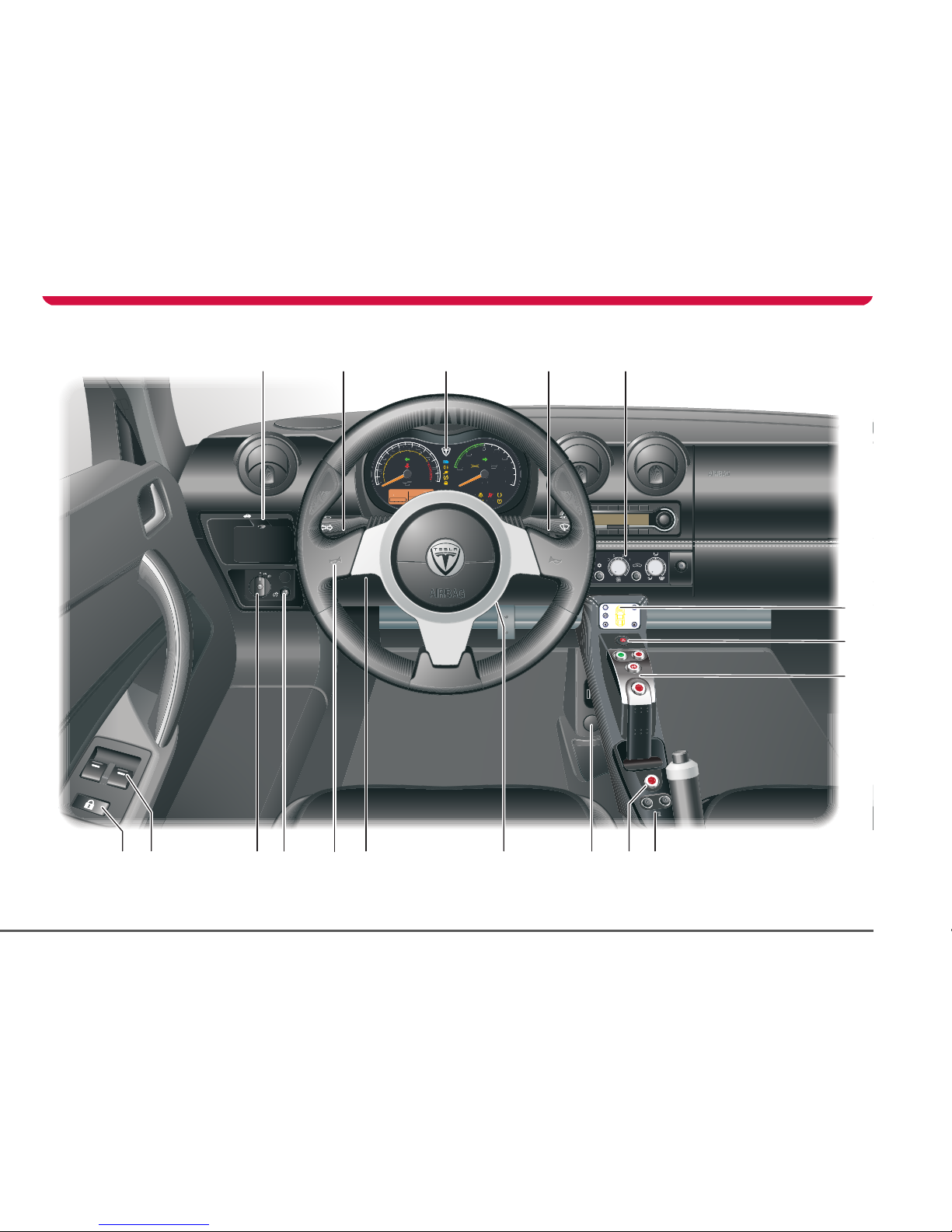
Dashboard overview
1. Trunk release. See Opening the trunk, page 4-6.
2. Turn signals, headlight high beam and cruise control. See Exterior lights, page 6-6 and Cruise control, page 6-9.
3. Instruments. See Instruments, page 6-11.
4. Windshield wiper and washer. See Windshield wiper and washer, page 6-8.
5. Heating and air conditioning. See Interior temperature control, page 7-4.
6. Touch Screen. See Touch Screen Users Manual provided in your owners package.
7. Hazard warning light switch. See Hazard warning, page 6-10.
8. Gear selector. See Selecting gears, page 6-3.
9. Seat heaters.Seat heaters, page 7-5.
10. Traction control switch. See Traction control, page 6-5.
11. Accessory power socket. See Accessory power socket, page 7-6.
12. Starter switch. See Starting the vehicle, page 6-2.
13. Hood release. See Opening the hood, page 8-3.
14. Horn. See Horn, page 6-10.
15. Instrument panel illumination control. See Instrument panel lighting, page 6-14.
16. Exterior lights master switch. See Exterior lights, page 6-6.
17. Power windows. See Operating the windows, page 7-2.
18. Central door locking. See Central door locking, page 4-4.
Page 15

3-1
Seating and safety restraints
Seats
Seat adjustment 3-2
Seat belts
General information 3-3
Seat belt safety instructions 3-3
Using the seat belts 3-3
Seat belt reminder 3-4
Wearing seat belts during pregnancy 3-4
Seat belt tensioners 3-4
Caring for seat belts 3-4
Child seats and restraints 3-5
Airbag system
General information 3-6
How the system works 3-6
Deployment effects 3-6
Obstruction of airbags 3-7
Airbag warning indicator 3-7
Airbag warning labels 3-7
Using child seats 3-7
Passenger airbag deactivation 3-7
Airbag service information 3-8
Page 16
Seats
3-2 Seating and safety restraints
Seating and safet y restraints
Seat adjustment
WARNING: Never adjust the driver’s
seat while your vehicle is moving.
Unexp ected or sudde n seat movement could
result in an accident.
S
Driver’s seat position
To adjust the forward/rearward position of
the driver’s seat, raise the bar beneath the
front of the seat and slide the seat to the
required position. Release the bar to lock the
TR0001
1
2
seat into position. Ensure that the seat is
locked in position before driving, by trying to
slide the seat forward.
To reduce the risk of injury in the event of an
accident, Tesla recommends the following
when adjusting seat position:
• Adjust the seat so that you can press the
foot pedals fully to the floor with your
knees slightly bent.
• Make sure that you can comfortably reach
the top of the steering wheel.
• Ensure a distance of at least 10 inches (25
cm) between the steering wheel and your
breastbone. The airbag will not provide
adequate protection if you sit closer.
• Fasten your seat belt correctly.
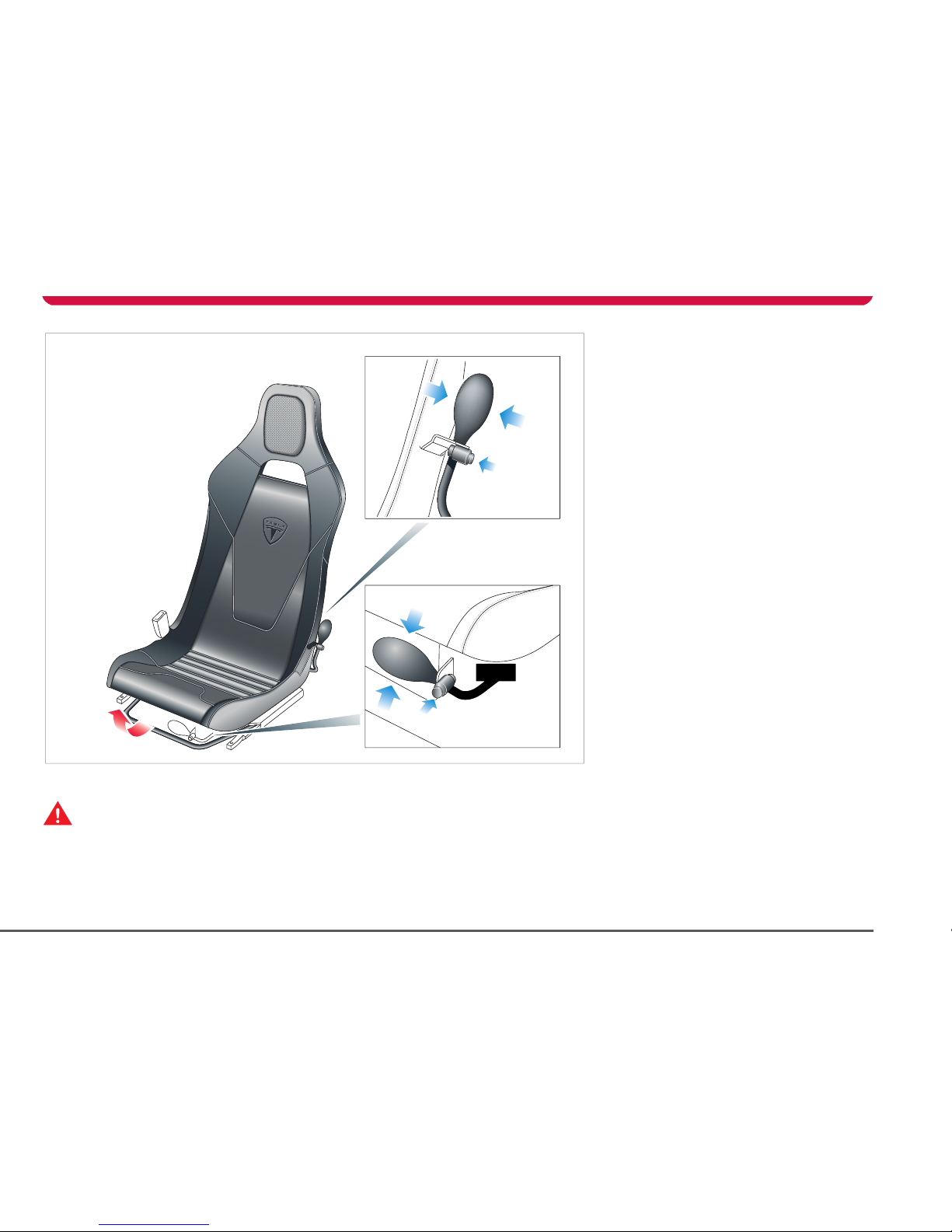
Lumbar support
Adjust lumbar support using the inflator bulb
located on the outside front edge of the
driver’s seat 1 or on the inside front edge of
the passenger seat 2.
To increase lumbar support, squeeze the bulb
repeatedly until sufficient support is obtained.
To reduce the amount of support, press the
button located on the clamp between the
hose and the inflator bulb.
Head restraints
Each seat is provided with a head restraint.
The head restraints are integral with the seats
and therefore can not be adjusted or
removed.
Page 17
Seat belts
3-3Seating and safety restraints
Seat belts
General information
WARNING: Seat belts should be worn
by all occupants, for every journey no
matter how short. Failure to do so greatly
increases the risk of death or serious injury in
the event of an accident.
S
It is an established fact that seat belts provide
good protection in accidents. Therefore
wearing a seat belt is required by law in most
states.
Both the driver and passenger seating
positions are equipped with three-point
inertia reel seat belts. Inertia reel belts are
tensioned automatically and allow freedom
of movement during normal driving
conditions.
The belt reel automatically locks, preventing
movement of occupants, whenever your
vehicle experiences the force associated with
hard acceleration, braking, cornering or on
impact in a collision. The reel may also lock
when driving on steep hills or slopes.
Seat belt safety instructions
WARNING: Ensure that all seat belts are
worn correctly. An improperly worn
seat belt increases the risk of death or serious
injury in the event of a collision.
S
WARNING: Seat belts are designed to
bear upon the bony structure of the
body, and should be worn low across the
pelvis, over the shoulder and across the
chest. Avoid wearing the lap section of the
belt across the abdominal area.
S
WARNING: Always adjust the belt to
remove slack. Seat belts worn too loose
can result in injuries because they allow
excessive forward movement in an
accident.
S
WARNING: Do not wear seat belts over
hard, fragile or sharp items in clothing,
such as pens, keys, eyeglasses, etc. In an
impact, the pressure from the seat belt on
such items can cause them to break, which in
turn may cause serious injury.
S
WARNING: Seat belts should not be
worn with any part of the strap
twisted.
S
WAR NI NG: Ea ch b el t as semb ly mu st b e
used by only one occupant. It is
dangerous to put the belt around a child
being carried on an occupant’s lap.
S
WARNING: It is essential that seat belts
that have been worn in an accident are
replaced, even if damage to the assembly is
not obvious. The belt anchors must also be
checked.
S
WAR NING : Ca re must be t ake n to avo id
contaminating the seat belt webbing,
and seat belt mechanisms with any
chemicals, liquids, grit, dirt or cleaning
products. If a seat belt fails to retract or latch
into the buckle, it must be replaced
immediately.
S
WARNING: No modifications or
additions should be made that prevent
the seat belt mechanism from taking up
slack, or that prevent the seat belt being
adjusted to remove slack. A slack belt greatly
reduces the level of occupant protection.
S
Using the seat belts
Fastening the belt
1. Ensure that the seat is correctly
positioned.
2. Take hold of the latch plate and pull it
slowly across your chest and lap.
3. Insert the latch plate into the buckle and
press down until you hear a “click” that
indicates it is securely locked into place.
4. Pull the belt to check that it is securely
fastened.
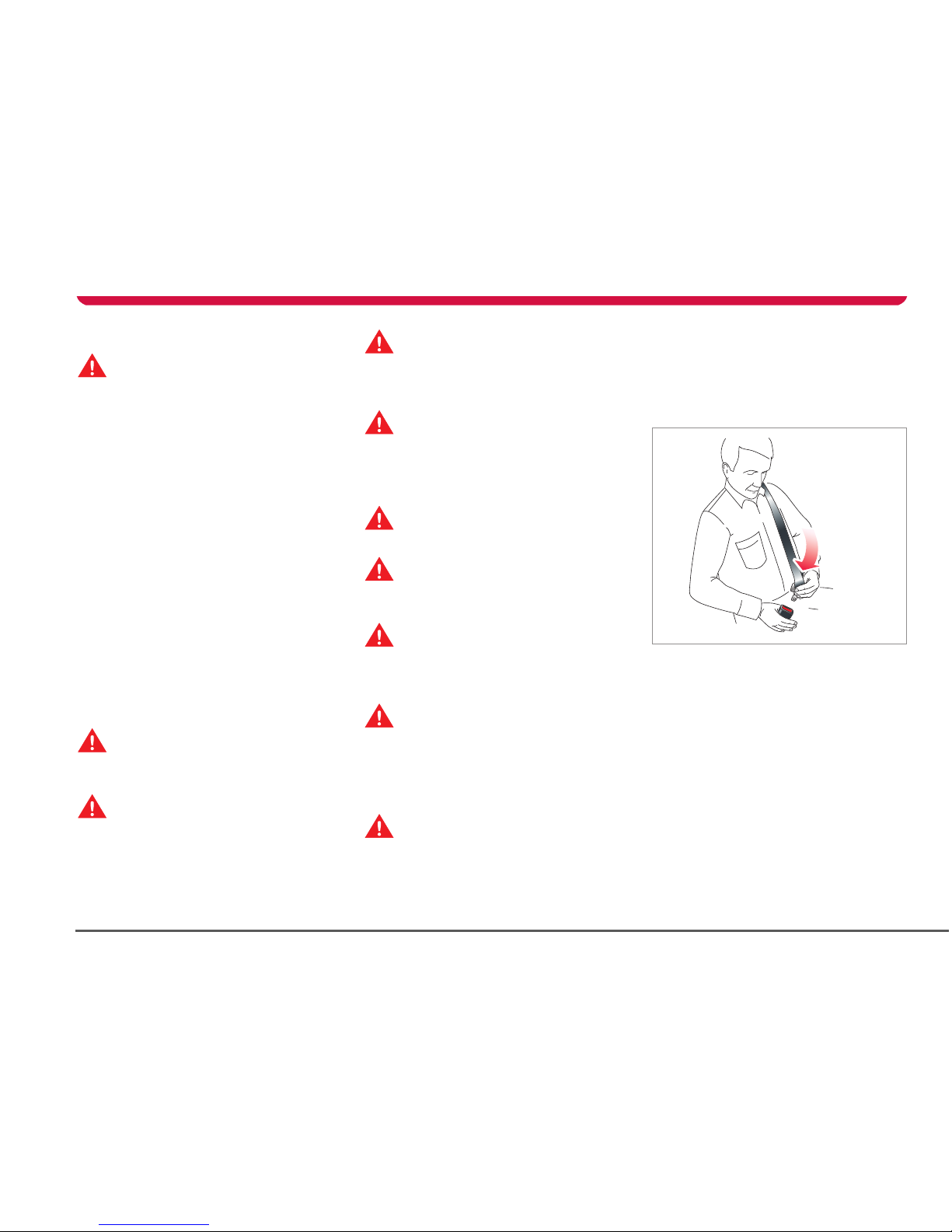
5. Position the belt so that it is worn low
across the front of the pelvis, and across
the chest and shoulder.
TR0139
Page 18
Seat belts
3-4 Seating and safety restraints
6. Pull the diagonal part of the belt towards
the retractor to remove excess slack.
Releasing the belt
Release the seat belts by pressing the red
button on the buckle. The belt retracts
automatically.
Seat belt reminder
The seat belt warning indicator in the
instrument panel illuminates
whenever the driver’s seat belt is unbuckled.
Also, an audible sound will be heard for six
seconds if the key is turned to the ON
position and the drivers seat belt is
unbuckled.
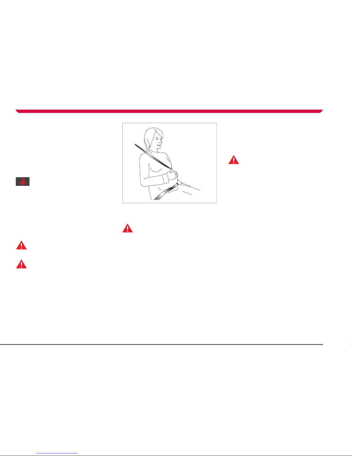
Wearing seat belts during
pregnancy
WARNING: Pregnant woman should
always wear seat belts to protect
themselves and their unborn child.
S
WARNING: Never place anything
between you and the seat belt to
cushion the impact in the event of an
accident.
S
The lap portion of the belt should be worn as
low as possible across the hips, not the waist.
Position the diagonal part of the belt
between the breasts and to the side of the
abdomen.
If you have any concerns about wearing seat
belts, contact your doctor.
Seat belt tensioners
WARNING: If the seat belt
pre-tensioners have been activated
once, they must be replaced. After any
accident, always have the airbags, seat belt
pre-tensioners and any associated
components checked and, if necessary,
replaced by Tesla Motors.
S
The seat belts are equipped with
pre-tensioners that activate in conjunction
with the airbags and provide additional
protection in the event of a severe frontal
impact on your vehicle.
The pre-tensioners automatically retract the
seat belt buckle, reducing any slack in both
the lap and diagonal portions of the belts,
resulting in reduced forward movement of
the occupant.
Following an accident in which the
pre-tensioners have been activated, the seat
belts continue to function as restraints and
must be worn if you drive your vehicle.
Caring for seat belts
WARNING: Regularly check the
condition of both belts. Replace seat
belts if you notice any damage to the belt
webbing, fittings, retractor mechanisms or
buckles.
S
Three tests for checking seat belts:
1. With the seat belt fastened, give the
webbing nearest the buckle a quick pull.
The buckle should remain securely
locked.
2. With the belt unfastened, unreel the
webbing to its limit. Check that unreeling
is free from snags and visually check the
webbing for wear. Allow the webbing to
retract, checking that retraction is
smooth and complete.
3. With the webbing half unreeled, hold the
tongue plate and pull forward quickly.
The mechanism must lock automatically
and prevent further unreeling.
If a seat belt fails any of these tests, contact
Tesla Motors immediately.
For seat belt cleaning information, see Seat
belts, page 8-9.
TR0140
Page 19

Seat belts
3-5Seating and safety restraints
Child seats and restraints
Currently, child seats and restraints are not
approved for use in your vehicle. Until these
are available, Tesla Motors strongly
recommends that children are not carried as
passengers in your vehicle.
WARNING: The seat belts fitted to your
vehicle are designed to secure adult
sized passengers only.
S
WAR NIN G: Child re n under age 12 and
those weighing less than 80 lb (36 kg)
are not of sufficient size to be carried safely
wearing a standard seat belt of the type
fitted to your vehicle.
S
WARNING: It is dangerous for children
to travel in any type of vehicle without
being restrained by a harness, child seat, or
restraint system suitable for both their age
and size.
S
WARNING: Never let a passenger hold a
child on his or her lap while your vehicle
is moving. The passenger cannot protect the
child from injury in a collision.
S
Page 20
Airbag system
3-6 Seating and safety restraints
Airbag system
General information
The airbag for the driver is located in the
padded hub of the steering wheel. The airbag
for the passenger is located on the
dashboard. These are indicated by the word
AIRBAG on the trim.
Provided the occupants are correctly seated
and the seat belts are properly worn, the
airbags provide additional protection to the
chest and face of the occupants in the event
of a severe frontal impact.
Note: Airbags inflate and deflate very quickly
and will not protect occupants against the
effects of secondary impacts that may occur.
How the system works
WARNING: The airbags are a
supplemental restraint system
providing additional protection in certain
types of collisions only - they do not replace
the need to wear a seat belt.
S
Operation of the airbag system depends on
the rate at which your vehicle's passenger
compartment changes speed as a result of a
collision.
In the event of a collision, the airbag control
unit monitors the rate of deceleration
induced by the collision to determine
whether the airbags should be deployed.
When deployed, airbags inflate instantly, with
considerable force accompanied by a loud
noise. The inflated bag, together with the
seat belt restraint system, limit the movement
of the occupants, thereby reducing the risk of
injury to the head and upper torso.
TR1322
1 2
The airbag system is not designed to operate
as a result of:
• Rear collisions
• Minor front impacts
• Minor side impacts
• Heavy braking
• Driving over bumps or potholes
It follows, therefore, that significant superficial
damage can occur without the air bags
deploying or, conversely, that a relatively small
amount of structural damage can cause the
airbags to be deployed.
Deployment effects
WARNING: Following inflation, some
airbag system components are hot. Do
not touch until they have cooled.
S
WARNING: The airbag module inflates
with considerable speed and force. An
inflating airbag can cause facial abrasions and
other injuries. To limit these injuries, ensure
that occupants are correctly seated, with the
seat as far back as is practical, and are
wearing seat belts.
S
WARNING: The National Highway Traffic
Safety Administration (NHTSA)
recommends a minimum distance of 10 inches
(25 cm) between an occupant’s chest and the
driver’s airbag module.
S
When the airbags are deployed, a fine powder
is released. This is not a malfunction. However,
the powder may irritate the skin and should be
thoroughly flushed from the eyes and from
any cuts or abrasions on the skin.
Page 21
Airbag system
3-7Seating and safety restraints
After inflation, the airbags will deflate to
provide a gradual cushioning effect for the
occupants and to ensure the driver's forward
vision is not obscured.
If the airbags have been deployed or if your
vehicle has been in an accident, always have
the airbags, seat belt pre-tensioners and any
associated components checked and, if
necessary, replaced by Tesla Motors.
Obstruction of airbags
WARNING: Do not allow passengers to
obstruct the operation of the airbags
by placing feet, knees or any other part of the
body, or any other objects in contact with, or
in close proximity to, an airbag module.
S
WARNING: Do not attach or position
items on an airbag cover which could
interfere with the inflation of the airbag or be
propelled inside your vehicle and injure
occupants.
S
Airbag warning indicator
A warning indicator in the instrument
panel alerts you of any malfunction of
the airbag system.
The components of the system being
monitored include: the airbag modules, the
seat belt pre-tensioners, the airbag control
unit and the airbag wiring harness.
When the key is turned to the ON position,
the airbag control unit monitors the readiness
of the system’s electrical circuits.
Contact Tesla Motors if:
• The warning indicator fails to illuminate
when the key is turned to the ON position.
• The warning indicator fails to extinguish
within approximately six seconds after
the key is turned to the ON position.
• The warning indicator illuminates while
your vehicle is being driven.
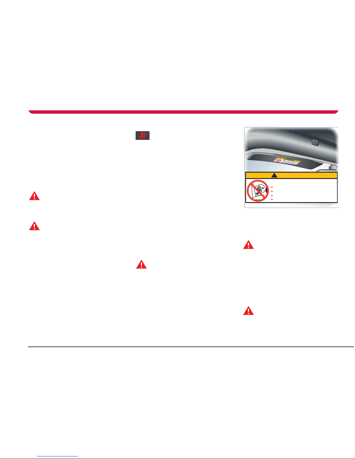
Airbag warning labels
WARNING: Extreme hazard! Do not use
a rearward facing child restraint on a
seat protected by an airbag in front of it.
Doing so increases the risk of death or
serious injury when the airbag deploys.
S
Airbag warning information is printed on the
driver’s and passenger’s sun visor.
Using child seats
WARNING: Currently, child seats and
restraints are not approved for use in
your vehicle. Until these are available, Tesla
Motors strongly recommends that children
are not carried as passengers in your vehicle,
and that you do not fit any type of child seat
into your vehicle. Death or serious injury may
occur if the child is too close to the
dashboard when the airbag inflates.
S
Passenger airbag deactivation
WARNING: Your vehicle is fitted with an
airbag system that has no provision for
switching off or deactivating the passenger
airbag.
S
!
WARNING
DEATH or SERIOUS INJURY can occur
Children 12 and under can be killed by the airbag
NEVER put a rear facing child seat in the front
Sit as far back as possible from the air bag
ALWAYS use SEAT BELTS and CHILD RESTRAINTS
TR0138
Page 22

Airbag system
3-8 Seating and safety restraints
Airbag service information
WARNING: The disposal of used airbag
units is subject to stringent regulations,
and should only be handled by Tesla
Motors.
S
For your safety, a Tesla Motors technician,
who is familiar with your vehicle, must
perform the following tasks:
• Removal, replacement, repair, or
modification, of any wiring or component
in the vicinity of airbag system
components, including the steering
wheel, steering column, dashboard and
instrument panel.
• Modification to the front or side of your
vehicle, including the bumper and
chassis.
In addition, always seek the assistance of
Te sla Moto r s i f :
• An airbag inflates
• A pre-tensioner activates
• The front or side of your vehicle is
damaged, even if the airbag has not
inflated
• Any part of an airbag module cover
shows signs of cracking or damage
Page 23

4-1
Doors, locks, and security
Keys
About your keys 4-2
Using the key fob 4-2
Doors
Exterior door release 4-4
Interior door release 4-4
Central door locking 4-4
Emergency unlocking 4-5
Glove box 4-5
Trunk
Opening the trunk 4-6
Closing the trunk 4-6
Trunk interior release handle 4-6
Vehicle security
Alarm System 4-7
Security PIN 4-7
PIN lock 4-9
Valet mode 4-10
Page 24
Keys
4-2 Doors, locks, and security
Doors, locks, and securityKeys
About your keys
Caution: The key fob contains delicate
electronic circuits and must be
protected from impact, water damage
and high temperatures. Avoid contact with
solvents, waxes and abrasive cleaners.
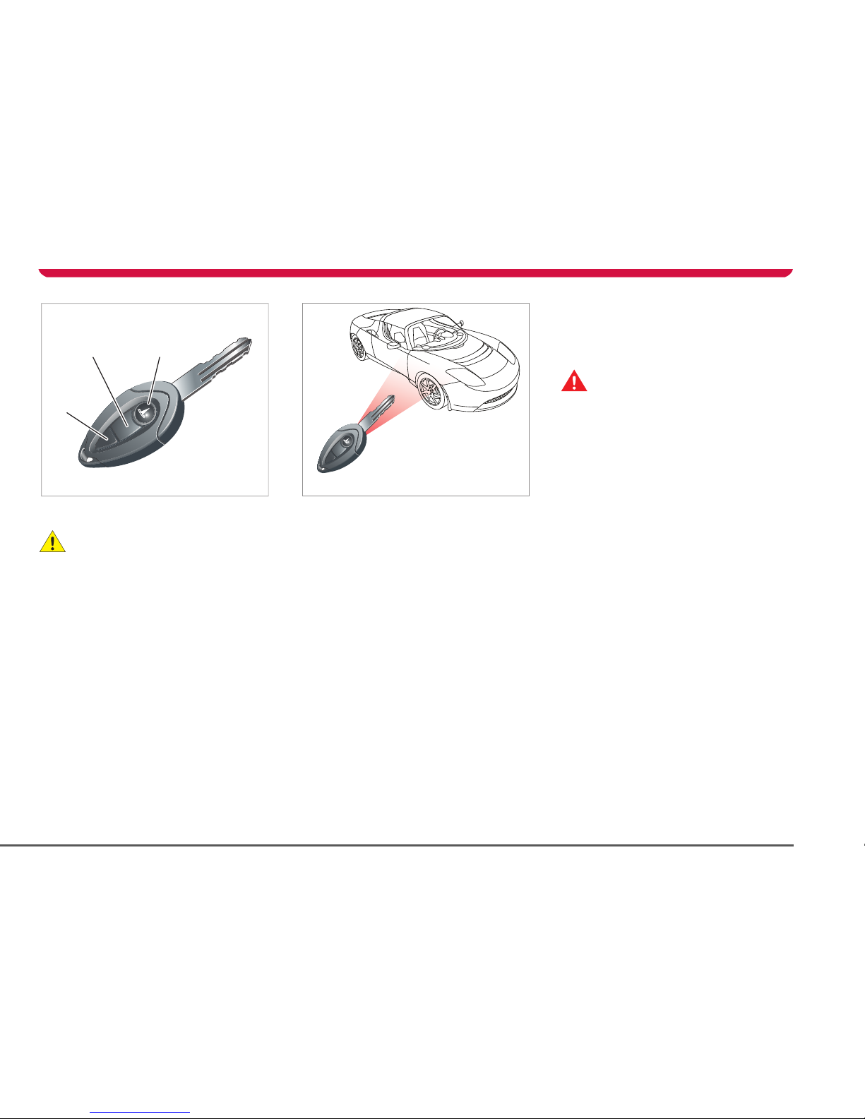
You have been supplied with three keys. Two
of the keys are key fobs with three buttons:
1. Lock button
2. Unlock button
3. Programmable button. See
Programmable button, page 4-3.
Keep one of the keys in a secure place for use
in emergencies. If you lose a key, contact
Tesla Motors for a replacement.
Using the key fob
The buttons on the key fob transmit a coded
radio signal to a receiver in your vehicle. It is
not necessary to point the key fob at your
vehicle, but you must be within operating
range and you must hold the button down for
two seconds. The operating range will vary
according to the key fob’s battery condition
and other physical factors.
If the vehicle can not be locked or unlocked
using the associated button on the key fob,
you may need to change the battery in the
key fob. See Replacing the key fob’s battery,
page 4-3.
Note: Interference from other radio
equipment operating on a similar frequency
may affect operation of the key fob. If this
happens, operate the key fob as close to your
vehicle as possible. If you are unable to
unlock your vehicle with the key fob, use the
emergency key lock. See Emergency
unlocking, page 4-5.
Locking
WARNING: Never leave anyone in your
vehicle when it is locked using the key
fob. The interior door release handles will
operate, but because the car was locked
using the key fob, the alarm will sound. To
re-open the doors using the exterior door
release handles, you must first disarm the
alarm using the key fob.
S
Press the Lock button on the key fob to lock
the doors and arm the alarm.
The turn signals will flash once and the red
security indicator on the console (illustrated
on page 4-7) will illuminate and continue to
flash red while the vehicle is locked. If you
push the Lock button after the vehicle has
already been locked, you’ll hear a
confirmation beep.
If a door, the hood or the trunk are not fully
closed when the lock button is pressed, the
turn signals will not flash and your vehicle is
not armed. Check that the doors, hood and
trunk are fully closed, then try again.
If an attempt is made to open the doors or
the hood from inside the vehicle after the
alarm has been set, the horn will sound and
the turn signals will flash for one minute. See
Alarm System, page 4-7.
TR1323
12
3
TR1333
Page 25
Keys
4-3Doors, locks, and security
Unlocking
Press the center button on the key fob to
unlock the doors and disarm the alarm.
The turn signals flash twice and the red alarm
indicator on the console extinguishes.
Note: If neither door or trunk are opened
within one minute, the doors will
automatically re-lock and the alarm will arm.
Programmable button
You can program the top button on the key
fob to perform one of the following functions:
• Alarm — sounds the horn and flashes the
exterior lights flash for one minute. Press
again to cancel the alarm.
• Trunk release — opens the trunk
• HomeLink
®
device — operates a
HomeLink device such as a garage door
or gate
By default, Tesla has programmed this key to
open the trunk. To re-program this button,
use the Touch Screen. Refer to the Touch
Screen Users Manual, provided in your
owners package.
To activate the programmed function, press
the button twice.
Replacing the key fob’s battery
The key fob’s battery should last for
approximately one year depending on use.
When the battery needs replacing, you’ll
notice a deterioration in performance. For
example, you’ll gradually need to be closer to
the vehicle to operate the key fob.
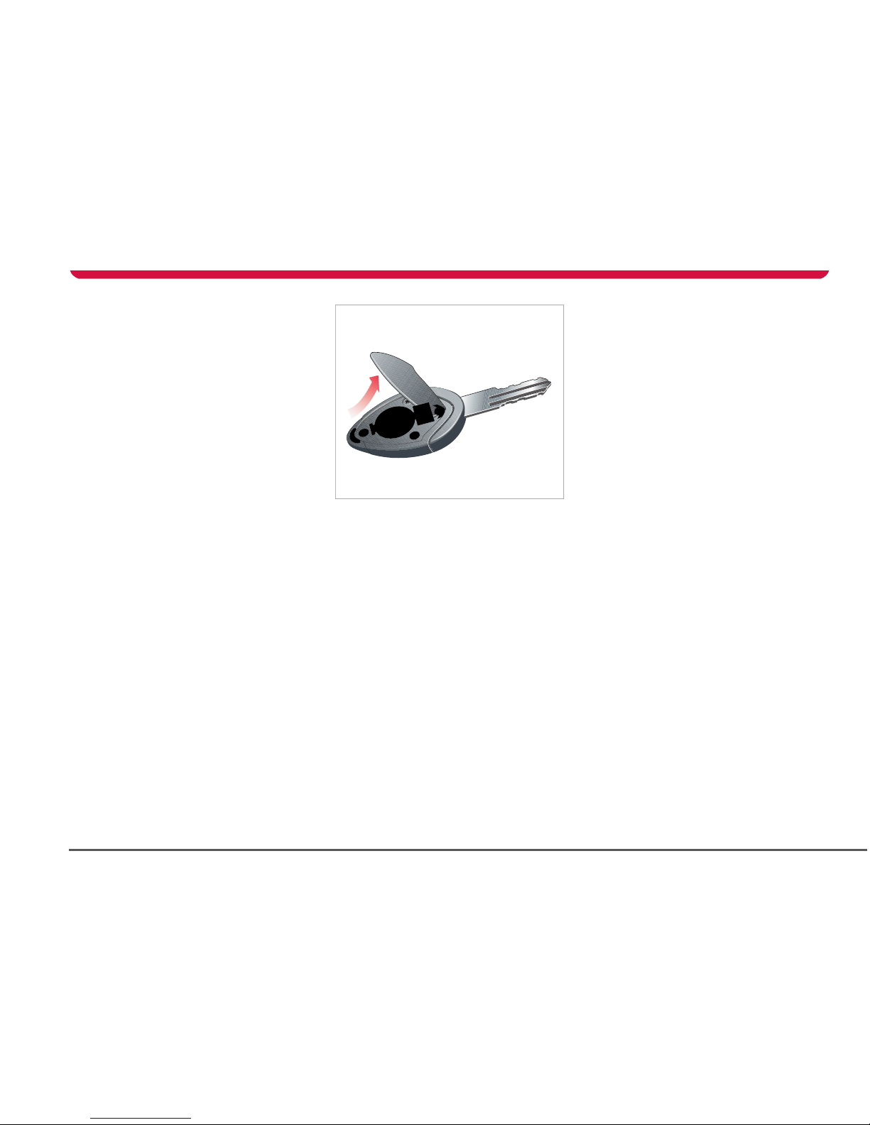
To replace the battery:
1. Insert a screwdriver into the top of the
key fob and carefully separate the two
halves. Avoid damaging the seal between
the two halves.
2. Remove the battery, taking care to avoid
touching the circuit board or the contact
surfaces of the battery holder.
3. Fit the new battery (type CR2032) with
the ‘+’ sides facing upwards.
If possible, avoid touching the flat
surfaces of the battery because finger
marks will reduce battery life. Wipe the
battery clean before fitting.
4. Re-assemble the two halves of the key
fob by aligning them and pressing them
together until they snap into place.
Compliance
The key fob complies with Part 15 of the FCC
rules and IC-RSS-210 Industry Canada.
Operation is subject to the following
conditions:
• This device may not cause harmful
interference.
• This device must accept any interference
received, including interference that may
cause undesired operation.
Any changes or modifications to the key fob
not expressly approved by the manufacturer
or Tesla Motors could void the user’s
authority to operate the equipment.
TR1334
Page 26
Doors
4-4 Doors, locks, and security
Doors
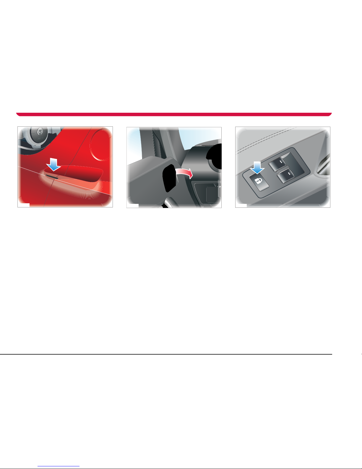
Exterior door release
With the doors unlocked, lightly press the
touch pad (located in the air inlet on the
door) to release the door. There is no need to
press hard. Pull the door to open.
Note: The door release touch pads operate
only if the doors are unlocked.
Interior door release
From inside your vehicle, pull the interior
door release handle to unlock and open the
door.
Central door locking
For your security, you can lock both doors
from inside your vehicle by pressing the
central locking switch on the driver’s door
panel. The doors will lock automatically when
the vehicle is being driven over 5 mph
(8 kmh).
Press the switch once to lock the doors and
inhibit the use of the exterior door release
touch pads. The alarm indicator on the
instrument panel will illuminate when the
doors are locked.
Press the switch to unlock the doors and
enable operation of the exterior door release
touch pads. You can also unlock the doors
using the key fob.
Note: The central door locking switch does
not operate if the doors have been locked
using the key fob. You’ll need to unlock the
TR0091
TR1335
TR0093
Page 27
Doors
4-5Doors, locks, and security
doors using the key fob. The central door
locking switch also does not operate if a door,
trunk, or the hood is not completely closed.
Drive away locking
For your security, the doors lock and the
trunk release switch is inhibited whenever
your vehicle’s speed exceeds 5 mph (8 kmh).
The trunk release button is reactivated when
your vehicle’s speed is less than 5 mph
(8 kmh).
Emergency unlocking
If the key fob fails to unlock the doors (for
instance if there is an electrical failure), you
can unlock the driver’s door using the
mechanical key.
A lock is located on the underside of the
driver’s door. Turn the key clockwise to
unlock the door.
Note: If active, the alarm will sound when the
door is opened. To cancel the alarm, press the
unlock button on the key fob or enter the PIN
Code on the Touch Screen. The default PIN
Code is 1234 but you can personalize this
code using the Touch Screen. For details,
refer to the Touch Screen Users Manual
provided in your owners package.
Glove box
To open the glove box, press the button
located on the dashboard immediately to the
left of the glove box.
To close the glove box, simply push it closed.
Note: The glove box will not open when the
alarm system is on.
TR1350
Page 28
Trunk
4-6 Doors, locks, and security
Trunk
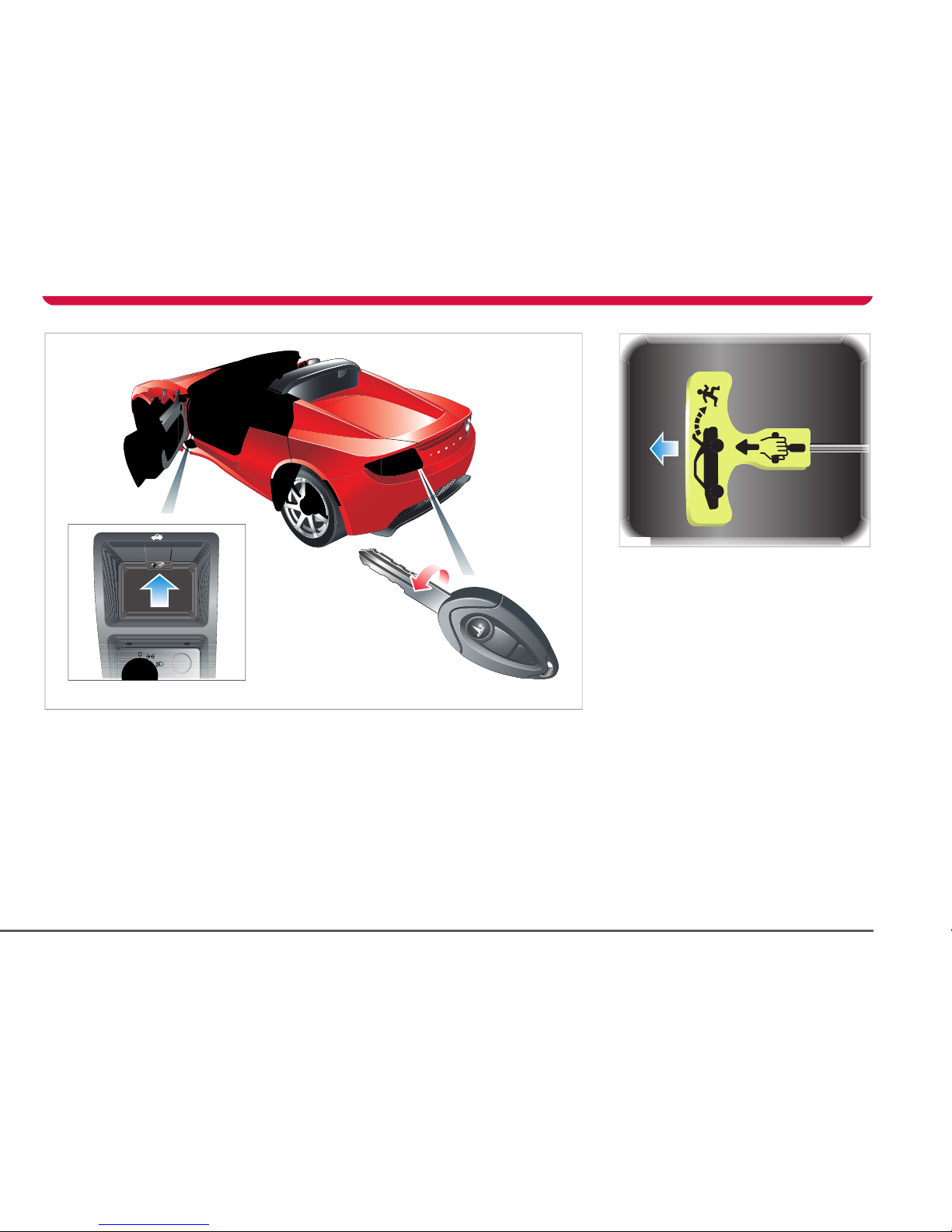
Opening the trunk
To open the trunk, press the trunk release
button on the dashboard, or insert the key in
the external lock and turn counter-clockwise.
You can also use the key fob if you have set
up its programmable button to remotely
open the trunk. For details on programming
the key fob, refer to the Touch Screen Users
Manual provided in your owners package.
The trunk release button is disabled when the
doors are locked with the key fob, or when
the vehicle’s speed exceeds 5 mph (8 kmh).
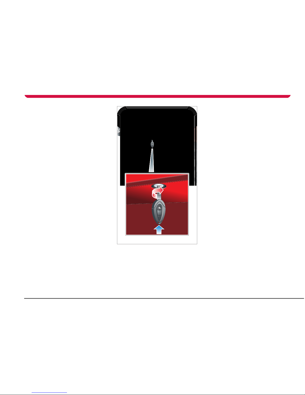
Closing the trunk
Close the trunk one side at a time. Use both
hands to firmly but gently apply downward
pressure on one side of the rear spoiler until
you hear it “click: into place. Repeat for the
other side.
TR1331
Trunk interior release handle
Your vehicle is equipped with a mechanical
trunk release handle that provides a means of
escape in the event that a person becomes
locked inside the trunk. Adults are advised to
familiarize themselves with the operation and
location of the release handle.
A T-shaped handle is located at the back of
the trunk towards the drivers side of the
vehicle. This handle is made using a
luminescent material that glows for hours
after a brief exposure to ambient light. To
open the trunk from the inside, pull the
T-shaped handle and push up on the trunk lid.
TR0149
Page 29
Vehicle security
4-7Doors, locks, and security
Vehicle security
Alarm System
Your vehicle is equipped with an anti-theft
alarm system. The alarm is switched on
automatically when you lock the doors with
the key fob. The turn signals flash once to
confirm that your vehicle is locked. The alarm
indicator on the instrument panel flashes red
when the vehicle is locked. An audible tone
will also be heard from inside your vehicle.
Once activated, the alarm monitors the
opening of the:
• Hood
• Doors
• Trunk
If a door is opened without the key fob, the
alarm sounds.
To switch off the alarm, unlock the doors
using the key fob or enter the PIN Code on
the Touch Screen.
Note: If the doors are unlocked with the key
fob, they will automatically re-lock if neither
the trunk or a door is opened within one
minute of the unlock button being pressed.
Alarm indicator
An indicator on the instrument panel
will flash red whenever the alarm
system is active.
An indicator on the instrument panel
will illuminate green whenever the
doors are locked and the alarm is not active.
If the vehicle didn’t lock
If the vehicle doesn’t lock when you press the
Lock button on the key fob, the turn signals
will not flash. Check that both doors, the
hood and the trunk are fully closed before
pressing the lock button again. If the problem
persists, contact Tesla Motors.
Switching off the alarm
If the alarm is triggered, the horn will sound
for one minute and the turn signals will flash
to attract attention. To silence the alarm,
press the UNLOCK button on the key fob or
enter your PIN code on the Touch Screen.
Note: Turning the key to the ACC position will
silence the alarm. However, it will not be
possible to start your vehicle until you either
press the Unlock button on the key fob or
enter the PIN code on the Touch Screen. For
details on using the Touch Screen, see the
Touch Screen Users Manual provided in your
owners package.
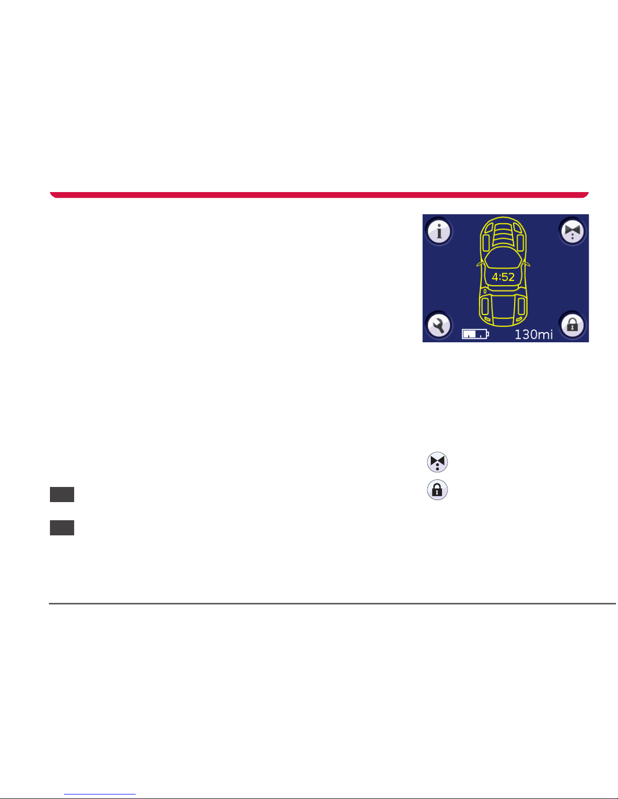
Security PIN
As an alternate level of vehicle security, you
can restrict operation of your vehicle until a
security PIN (Personal Identification
Number) is entered. The security PIN is used
by the following features that can be selected
on the Touch Screen’s parked screen (shown
above— the parked screen is active whenever
the hand brake is engaged).
You can also use the security PIN to turn off
the vehicle’s alarm.
The default PIN code is 1234. Tesla Motors
strongly recommends that you change this to
a unique PIN code. If you sell your vehicle,
you’ll need to tell the new owner the security
PIN you have set.
Val et mo de . S ee Val et mo de ,
page 4-10.
PIN Lock. See PIN lock,
page 4-9.
Page 30
Vehicle security
4-8 Doors, locks, and security
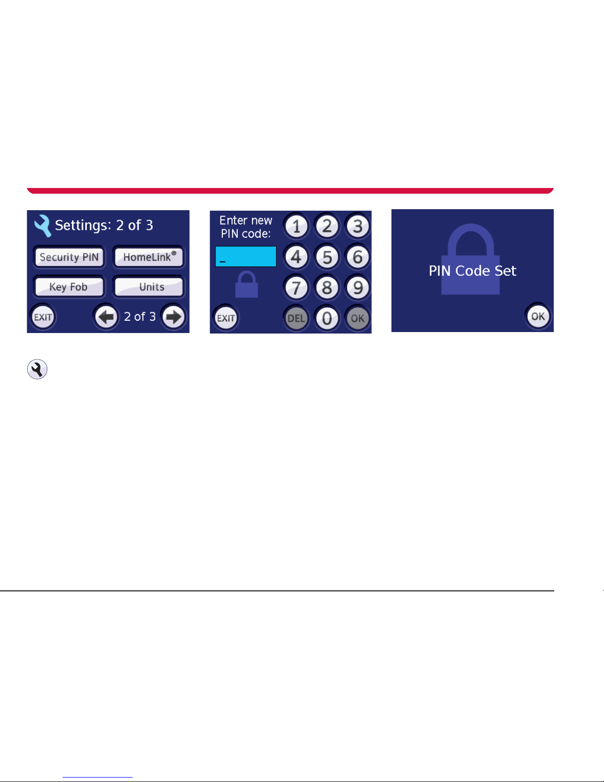
Setting the security PIN
With the hand brake engaged, touch
the SETTINGS icon on the main parked
screen (or any of the drive screens) to
display the settings screens.
Press the right arrow icon to navigate to the
second settings screen.
To u ch Security PIN.
You will be asked to enter the old PIN code.
Enter the old PIN code (if you haven’t
previously set a PIN code, the default code is
1234) by touching the numbers on the screen
and then touch OK. If you enter an incorrect
PIN code, an invalid entry message will be
displayed. Either enter the correct PIN code
or touch the EXIT icon to return to the
previous screen.
You will be then be asked to enter the new
PIN code. Enter a new PIN code and then
touch OK.
Note: The PIN code must be between four
and eight digits in length.
You will then be a sked to c onfi rm t he new PIN
code. Enter the new PIN code again and then
touch OK.
If the PIN code does not match the previously
entered code a message will be displayed
telling you that the PINs differ and you will
need to enter the PIN code again.
If the PIN codes match, then the PIN Code Set
screen will be displayed.
Touch OK to return to the Settings screen.
Note: Always keep a record of your PIN code
and store it in a safe place. Do not store your
PIN code in your vehicle.
Page 31

Vehicle security
4-9Doors, locks, and security
PIN lock
When activated, the PIN lock inhibits starting
and driving your vehicle until the PIN code is
entered on the Touch Screen.
Activating PIN lock
To activate the PIN lock, touch the
LOCK icon on the main parked screen.
Enter your PIN code. The Touch Screen
displays a message (shown above) telling you
that the PIN lock is activated.
If a PIN code has not been set, the Touch
Screen displays a message telling you to
enter a new PIN code. Touch OK to enter a
new PIN code. See Security PIN, page 4-7.
Deactivating PIN lock
To deactivate the PIN lock, touch the
UNLOCK icon to display the PIN code
entry screen.
Enter your PIN code and then touch OK. If the
correct PIN code was entered, the Touch
Screen displays the main parked screen.
If you enter an incorrect PIN code, a message
is displayed telling you that you’ve made an
invalid entry. Either enter the correct PIN
code or touch the EXIT icon to return to the
previous screen.
Page 32

Vehicle security
4-10 Doors, locks, and security
Valet mo de
For your peace of mind, your vehicle has a
unique valet mode for those times that your
vehicle is parked by another person.
When valet mode is active, your vehicle’s
power is limited and the Touch Screen
displays activity information about the
vehicle. The maximum speed the vehicle can
travel in valet mode is 50 mph (80 kmh).
Operation of the Touch Screen is restricted to
the valet mode screen which displays
information on how your vehicle was used
while in valet mode.
Valet mode can only be deactivated by
entering the vehicle’s PIN code.
Activating Valet mode
To activate valet mode, touch the bow
tie icon on the Touch Screen’s main
parked screen.
Provided a vehicle PIN code has been set,
you’ll be prompted to enter your PIN code.
Enter your PIN code and touch OK. The Touch
Screen displays the Valet Mode Activated
screen.
If a PIN code has not been set, the Touch
Screen displays a message telling you to
enter a new PIN code. Touch OK to enter a
new PIN code. See Security PIN, page 4-7.
The Touch Screen displays the following
information for the current period that valet
mode has been active:
• Distance travelled
• Top speed reached
• Unlock attempts (the number of
unsuccessful attempts at entering a PIN
code)
• Trunk openings (the number of times the
trunk has been opened)
Deactivating Valet mode
To deactivate valet mode, touch the
UNLOCK icon to display the PIN code
entry screen.
Enter your PIN code and then touch OK. If the
correct PIN code was entered, the Touch
Screen displays the main parked screen.
If you enter an incorrect PIN code, a message
is displayed telling you that you’ve made an
invalid entry. Either enter the correct PIN
code or touch the EXIT icon to return to the
previous screen.
Page 33

5-1
Charging your vehicle
General information about charging
Important! 5-2
The Battery 5-2
Designed to be plugged in 5-2
Leaving the vehicle unplugged 5-2
Storing your vehicle 5-3
Maximum level of charge 5-3
Charge level and range are estimates 5-3
How long does it take to charge? 5-3
Charge settings
About charge settings 5-4
Four charge modes 5-4
Schedule the charge time 5-5
Setting current limit 5-5
Cost 5-5
Charging components
Charging components 5-6
Mobile connector 5-6
Page 34

General information about charging
5-2 Charging your vehicle
Charging your vehicleGeneral information about charging
Important!
Caution: If the Battery’s charge level
falls to 0%, it must be plugged in
immediately. Failure to do so can
permanently damage the Battery and this
damage is not covered by the New Vehicle
Limited Warranty. Also, if you allow the
Battery to fall to a critically low level it may
not be possible to charge the vehicle. If you
are unable to charge the vehicle, contact
Te sla Mo tors.
WARNING: The Battery has no parts
that an owner, or a non-Tesla authorized
technician can service. Under no
circumstances should you open or tamper
with the Battery. Always contact Tesla Motors
to arrange for Battery servicing
.S
At the end of its service life, the Battery
will be recycled. Contact Tesla Motors
for recycling arrangements.
The Battery
The Tesla Roadster’s Battery provides power
to the motor as well as all the other electrical
systems on the vehicle, such as lights,
instruments, audio system, etc.
The Battery is one of the largest and most
advanced battery packs in the world,
consisting of several thousand lithium-ion
battery cells that store enough energy for the
vehicle to travel over 200 miles (320 kms)
without recharging.
Note: Actual range will vary based on driving
style. The vehicle consumes more energy if
you are driving aggressively, driving up hills,
or are using more resources such as air
conditioning. Also, over time, the Battery
experiences a gradual loss of capacity,
inherent in all lithium-ion batteries. So, as
your vehicle ages, the capacity of the Battery
declines.
As you drive your vehicle, the level of charge
in the Battery is depleted and you’ll need to
recharge it. The Roadster’s built-in charging
system allows you to easily recharge it by
connecting an electrical power supply to the
vehicle’s charging port.
Designed to be plugged in
The Tesla Roadster is designed to be plugged
in when not in use. This ensures that the next
time you use the vehicle, it is fully charged
and ready to go. There is no advantage to
waiting until battery level is low before
charging. Plugging in every night eliminates
the risk of damage that could be caused by
over-discharging the battery.
When plugged in, the vehicle optimizes the
lifetime of the Battery by managing its
charge level and temperature. The vehicle
wakes up every 24 hours and, if needed,
automatically initiates the charging process
to keep the Battery at an optimum charge
level.
If you’re not driving your vehicle every day,
see Storing your vehicle, page 5-3.
Leaving the vehicle unplugged
Even when you’re not driving the vehicle, the
Battery will slowly lose its charge. Therefore,
when you’re not using the vehicle, you should
leave it plugged in. However, situations may
arise in which you must leave the vehicle
unplugged for an extended time (for
example, at an airport when travelling for a
couple of weeks). If this is the case, it is your
responsibility to ensure that the Battery does
not become fully depleted. Charge the
Battery to a maximum level before leaving it.
Keep in mind that when the vehicle is left
unplugged with a full Battery, the initial rate
of decline can be significant. When fully
charged, the Battery’s charge level can drop
as much as 7% a day and 50% within the first
week. When the Battery’s charge level falls
below 50%, the rate of decline slows down to
approximately 5% per week. Over-discharge
can permanently damage the Battery.
If for some reason, you are unable to keep the
vehicle plugged in when it is not being used,
it is up to you to preserve battery life by
paying attention to the charge level and the
temperature (see bulleted list below). If
leaving your vehicle unplugged for more than
24 hours, follow these do’s and don’ts to
avoid prematurely decreasing the life of your
vehicle’s Battery:
• DO leave the vehicle plugged in whenever
possible.
• DO maintain at least a 15% charge level in
the Battery if leaving it unplugged for
more than 48 hours.
Page 35

General information about charging
5-3Charging your vehicle
• DO charge the Battery to a full charge
before leaving it unplugged. This
maintains the charge level needed to
keep the Battery’s electronics
operational. If storing for more than 15
days, it is strongly recommended that you
keep it plugged in.
• DO NOT expose an unplugged vehicle to
ambient temperatures below -20°F
(-29°C) or above 120°F (49°C.
Use the vehicle’s Touch Screen to determine
the charge level and temperature of the
Battery. For details, refer to the Touch Screen
Users Manual, provided in your owners
package.
Storing your vehicle
If you plan to leave the vehicle unused for
longer than 15 days, it is recommended that
you leave the vehicle connected to the High
Power Connector and select the ‘Storage’
charge setting using the Touch Screen. When
you charge the vehicle using the Storage
charge setting, the vehicle is automatically
kept at a reduced charge level to optimize the
life of the individual cells within the Battery.
Keep in mind that the reduced charge level
also reduces the vehicle’s available driving
range. So remember to change the setting
back to ‘Standard’ before taking the vehicle
on an extended drive. For details on how to
select the Storage charge setting, refer to the
Touch Screen Users Manual, provided in your
owners package.
Maximum level of charge
The maximum level of charge the Battery will
be charged to depends on the charge setting
you select (see About charge settings,
page 5-4). The Standard charge setting is the
preferred setting for normal use. Selecting
the Range or Performance charge settings
will charge the Battery to its maximum
allowable charge level, whereas selecting the
Storage charge setting will charge the
Battery to a relatively low level.
Charge level and range are
estimates
The vehicle’s Touch Screen displays the
charge level and number of miles you can
drive on the remaining charge. The numbers
that are displayed are estimates only. The
Touch Screen allows you to display these
estimates based on how you’ve been driving
for the last 40 miles (64 kms) (EST RANGE)
or how many miles you can achieve in ideal
driving situations (IDEAL RANGE). Therefore,
if you have been driving on hills for the past
40 miles (64 kms), and you are now driving
on a flat highway, the number of miles you
can drive on the remaining charge will
actually be more than the estimate that is
displayed when EST RANGE is selected.
Likewise, if you are displaying remaining
miles based on IDEAL RANGE, but are using
the vehicle’s air conditioning system and
driving aggressively, the number of miles you
can drive on the remaining charge will be less
the estimate that is displayed. Charge level
and estimated remaining mileage are also
displayed on the vehicle’s LCD panel (see
page 6-11).
The charge level and estimated mileage are
continuously updated. Also, they may be
lower or higher after a period of rest. For
example, when parking your vehicle you
notice that the estimated remaining mileage
is 85. When returning to your vehicle a few
hours later, you notice that the estimated
mileage is now 91. This is normal behavior and
is not a cause for concern. The mileage that is
displayed when the vehicle has been at rest is
more accurate.
How long does it take to charge?
The amount of time it takes to fully charge
the vehicle will vary depending on current
and voltage. Charge time is also impacted by
both the ambient temperature and the
vehicle’s Battery temperature—if out of the
optimal range, the HVAC system starts up
and diverts a portion of the energy. It also
depends on the charge setting you are using.
For example, a full charge at Range or
Performance takes approximately 15% longer.
Use the following table as a guideline when
estimating how long it will take to charge
your vehicle. This table assumes you are
charging a fully depleted Battery to a full
charge using the Standard or Range charge
setting. Charge times are estimates only.
Page 36

Charge settings
5-4 Charging your vehicle
Note: The charge process slows down as the
Battery approaches a full charge. Therefore,
reaching a high level of charge is much
quicker than reaching a full charge.
Charge settings
About charge settings
Your vehicle has been set up with default
charging settings. However, you can override
these default settings. You may want to
optimize the charging environment when
storing your vehicle, or you may want to
extend the vehicle’s driving range. You can
also reduce the default charge current, set a
time that you want charging to begin, and
display your electrical cost per charge.
Charge settings can be changed using the
Touch Screen. The various charge settings
are summarized below. For details on how to
use the Touch Screen to adjust settings, refer
to the Touch Screen Users Manual, provided
in your owners package.
Four charge modes
The charge mode always defaults to
Standard charge. In other words, changing
the charge type is a one-time event—the
charge type reverts back to Standard the
next time the charging port door is opened
after the vehicle has been driven over a tenth
of a mile (.16 kms).
Storage
If you are not using the vehicle for an
extended period of time, Tesla recommends
leaving the vehicle plugged in and setting the
charge type to Storage.
This setting charges the Battery to a medium
level of charge to ensure the maximum
lifetime of the cells within the Battery, while
also maintaining the integrity of the vehicle’s
electronic systems, such as the security
system.
This charge setting is automatically cancelled
and reverts back to Standard if the vehicle’s
charging port door is opened after the
vehicle has been driven over a tenth of a mile
(.16 kms).
If the vehicle is driven after being charged
using the Storage setting, the range of the
vehicle will be limited because the charge
level is lower than the other charge types.
This is temporary and returns to normal after
charging the vehicle using the Standard
setting.
Standard
By default, the vehicle is set up to charge
using the Standard charge setting—this
setting provides the best performance while
also maximizing the life of the Battery.
Range
This setting charges the Battery to the
maximum available level. It also limits the
vehicle’s power by 50%. The result is that the
vehicle can achieve the maximum number of
miles possible on a single charge.
To preserve the life of the Battery, this charge
setting is automatically cancelled and reverts
back to Standard after 72 hours or when the
vehicle’s charging port door is opened after
the vehicle has been driven over a tenth of a
mile (.16 kms).
Caution: Repeated use of the Range
charge setting reduces the lifetime of
the cells within the Battery.
Performance
This setting is available for those rare times in
which you want to achieve maximum power
and hence, minimize the time it takes to
accelerate from 0-60 mph (0-100 kmh). Use
this setting with caution because it allows the
Battery to run at a higher temperature—
which reduces the life of the cells within the
Battery. Frequent use of this setting is
strongly discouraged.
Charge
Specification
(amps/voltage)
Charge TIme
in Standard
mode
Charge Time
in Range
mode
12A/120V 48 hours 54 hours
15A/120V 37 hours 41.5 hours
10A/240V 23.5 hours 26.5 hours
13A/240V 18 hours 20 hours
16A/240V 14.5 hours 16 hours
24A/240V 10 hours 11 hours
30A/240V 8 hours 9 hours
32A/240V 7.5 hours 8 hours
40A/240V 6.2 hours 7 hours
48A/240V 5.3 hours 6 hours
56A/240V 4.7 hours 5 hours
64A/240V 4.2 hours 4.7 hours
70A/240V 4 hours 4.5 hours
Page 37

Charge settings
5-5Charging your vehicle
This setting also charges the cells within the
Battery to the maximum available level.
To preserve the life of the Battery, this charge
setting is automatically cancelled and reverts
back to Standard after 72 hours or if the
vehicle’s charging port door is opened after
the vehicle has been driven over a tenth of a
mile (.16 kms).
Caution: Repeated use of the
Performance setting reduces the
lifetime of the cells within the Battery.
Schedule the charge time
If you don’t want the vehicle to begin
charging immediately after you plug it in, you
can set a charge start time. This is a useful
way to charge the vehicle during non-peak
hours when there is less demand on your
electrical system and your electricity may
cost less.
Setting current limit
The charging current is automatically set to
the maximum possible value available from
the attached power supply. With the
charging port door open, you can use the
Touch Screen’s charge settings screen to
manually change the current. If you do so, the
changed value remains in effect for the
current location until you manually change it.
The vehicle location is determined by the
internal global positioning system (GPS). This
allows you to set a different current limit for
each of your charging locations.
Cost
You can display the cost of a charge on the
Touch Screen when the vehicle has finished
charging. You can obtain an accurate reading
of your power cost for each charge cycle by
entering the cost of power (in kWh) on the
Cost Settings screen. In most areas, you can
obtain your power costs from your utility bill.
For details on setting charge costs, refer to
the Touch Screen Users Manual provided in
your owners package.
Page 38

Charging components
5-6 Charging your vehicle
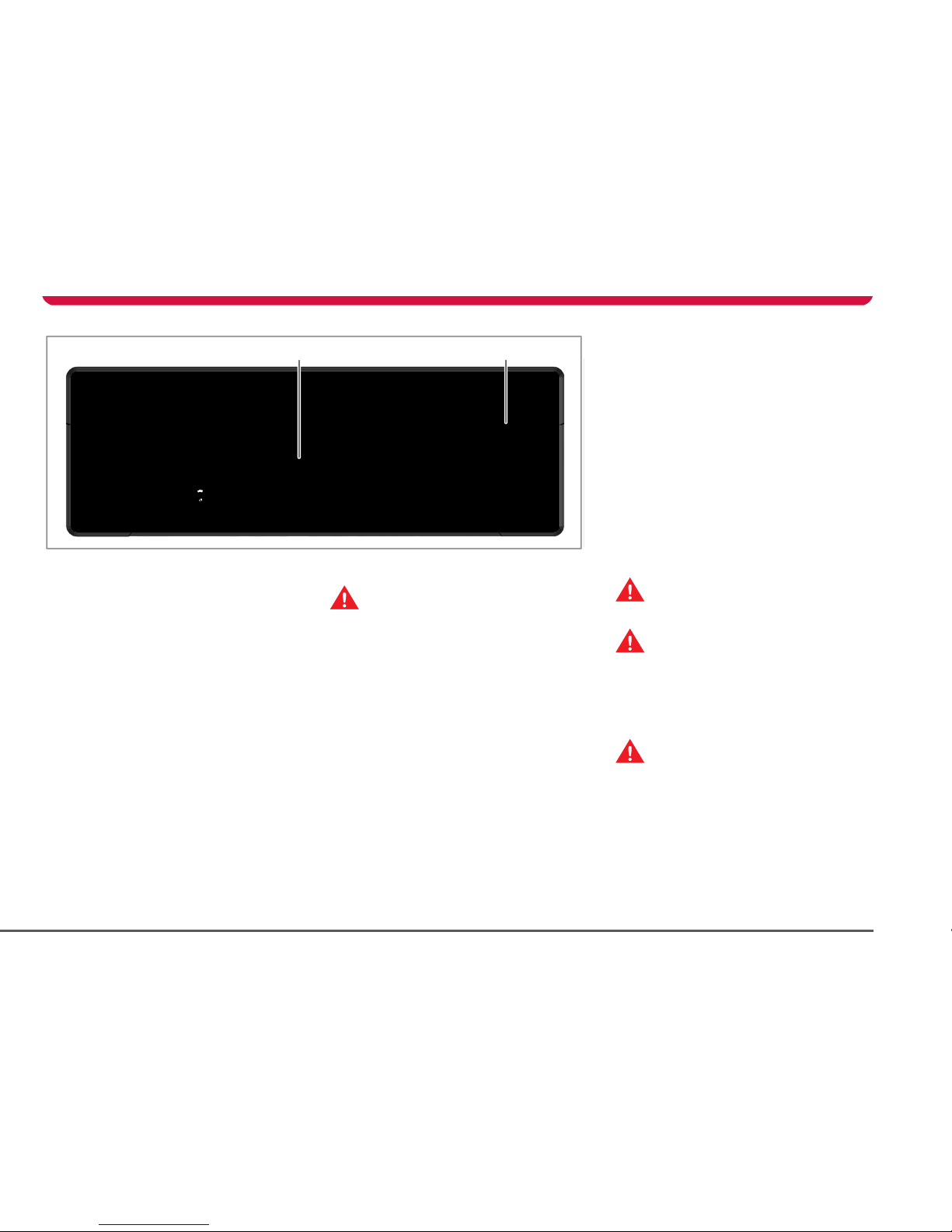
Charging components
1. Battery
2. Charging port door
3. Charging cable connector
4. Charging cable
5. Cable hanger
6. High Power Connector
Charging components
A Tesla Motors High Power Connector is the
fastest way to recharge your vehicle.
During normal use, the High Power Connector
should be left on, even when the charging
cable is not connected to the vehicle. The
READY light on the control panel illuminates
green to indicate that the High Power
Connector is operating correctly.
Although the High Power Connector is on and
ready, no electricity is supplied until you
connect the charging cable to the vehicle, and
both the vehicle and the High Power
Connector determine that it is safe for
charging to begin.
For details on how to use the High Power
Connector to charge your vehicle, refer to the
manual titled “Charging Your Vehicle,”
provided in your owners package.
Mobile connector
The Tesla Motors Mobile Connector connects
into most power outlets to allow you to
charge your vehicle when you are away from
home. Its small size allows it to be carried in
the vehicle’s trunk. Keep in mind that it takes
longer to charge the vehicle using the Mobile
Connector than when using the High Power
Connector. Always check the vehicle’s charge
level before driving and plan your drive and
charging requirements accordingly. For
details on how to use a Mobile Connector to
charge your vehicle, refer to the manual titled
“Charging Your Vehicle,”
Roadster OHB.book Page 6 Monday, August 24, 2009 5:26 PM
Page 39

6-1
Driving your vehicle
Driving basics
Starting the vehicle 6-2
Key positions 6-2
Steering column lock 6-3
Selecting gears 6-3
Driving tips 6-3
Hand brake 6-4
Braking 6-4
Anti-lock Braking System (ABS) 6-5
Traction control 6-5
Switches and controls
Exterior lights 6-6
Turn signals 6-7
Windshield wiper and washer 6-8
Cruise control 6-9
Hazard warning 6-10
Horn 6-10
Instruments
Instrument panel components 6-11
Power meter 6-11
LCD panel 6-11
Warning indicators 6-12
Instrument panel lighting 6-14
Page 40

Driving basics
6-2 Driving your vehicle
Driving your vehicleDriving basics
Starting the vehicle
To start the vehicle, turn the key to the ON
position.
All warning indicators on the instrument
panel will illuminate briefly. When these
indicators extinguish and the gear selector
buttons illuminate, the vehicle is ready to be
driven.
To drive the vehicle, press the brake pedal
and press the D (Drive) or R (Reverse) gear
button. Place your foot on the brake pedal to
change the gear out of P (Park) or N
(Neutral).
Key positions
The starter switch has the following key
positions to control the electrical circuits and
steering column lock.
OFF
When the key is OFF, the vehicle is
automatically in the P (Park) gear position
and the following features are operational:
• Touch Screen
All interior and exterior lights (including
trunk light and hazard warning lights)
• Central door locking switch
• Tru nk rel ea se switch
Note: When you turn the key to the OFF
position, the circuits that operate in ACC
continue to operate until you remove the key.
ACC
In addition to the features that operate when
the key is OFF, the following features operate
when the key is in the ACC position:
• Audio and navigation systems
• Brake lights
• Windows
• Seat heaters
• LCD panel
ON
When the key is in the ON position, all
controls and switches, lights, instruments,
warning indicators and electrical circuits are
operational.
PERFORMANCE
Move the key all the way forward to engage
“Performance” mode. In Performance mode,
you can achieve maximum power and
minimize the time it takes to accelerate from
0-60 mph (0-100 kmh). When in
Performance mode, you’ll notice a small blue
letter “P” in the upper right-hand corner of
the Touch Screen’s Drive screen.
Note: You will be unable to use the key to
engage Performance mode within the first 10
seconds of starting the vehicle, or if you are
driving in Range mode with the Battery
almost fully depleted.
Use this mode with caution because it allows
the Battery to run at a higher temperature—
which reduces the life of the cells within the
Battery. Frequent use of this setting is
strongly discouraged.
To cancel Performance mode, turn the key all
the way forward again. You can also cancel it
using the Touch Screen.
You can also engage Performance mode at
any time using the Touch Screen. For more
information, see Performance, page 5-4 or
refer to the Touch Screen Users Manual
included in your owners package.
Removing the key
To remove the key, turn the key to the OFF
position. Exterior lights (except hazard
warning lights) automatically turn off when
you remove the key.
If you leave the key in and open the driver’s
door, you’ll hear an audible alert reminding
you to remove the key.
WARN ING : N ever remove th e ke y whe n
the vehicle is moving. The steering
column will lock and you can no longer steer
the vehicle.
S
10TR0004
OFF
ACC
ON
PERFORMANCE
Page 41

Driving basics
6-3Driving your vehicle
Steering column lock
The steering column locks whenever you
remove the key. You may need to turn the
steering wheel slightly to align the
mechanism that engages the lock.
To release the steering column lock, turn the
key to the ACC position. If it is difficult to turn
the key, turn the steering wheel slightly.
Selecting gears
The vehicle has four selectable gear
positions. When a gear is engaged, it’s
associated button illuminates green.
• P (Park). Selectable whenever the
vehicle’s forward speed is less than 1 mph.
To select another gear when the vehicle is
in Park, you must press the brake pedal.
Whenever the key is in the OFF position,
Park is activated autom atically, regardless
of which gear was engaged before you
turned the key.
• N (Neutral). Allows the vehicle to be
stationary without the transmission being
locked. If the hand brake is not engaged,
the vehicle can roll freely if pushed, or if
located on a slope. To select another gear
when the vehicle is in Neutral and moving
at a speed less than 5 mph (8 kmh), you
must press the brake pedal.
• R (Reverse). Selectable whenever the
vehicle’s forward speed is less than 5 mph
(8 kmh). The maximum speed in reverse is
limited to 15 mph (24 kmh). An audible
tone will be heard when you select
Reverse.
• D (Drive). Can be selected at any time
except when the vehicle is moving over 5
mph (8 kmh) in reverse.
When a gear is engaged, its associated
button illuminates green. If you select a gear
that is not allowed in the current situation (for
example, you select Reverse when driving
forward over 5 mph (8 kmh), its associated
button illuminates red to indicate that the
gear change is denied.
Similar to a conventional automatic
transmission, when you select Drive or
Reverse, the vehicle will move, even if you
have not pressed the accelerator pedal.
Note: When in Park, the transmission is
locked and the rear wheels cannot turn. In
the event that the vehicle needs to hauled
on a flatbed truck, Park must be deactivated
before the vehicle can be pulled onto the
truck. You can pull the vehicle by selecting
Neutral or by using the Touch Screen to
activate Tow Mode. For details, see Vehicle
recovery, page 9-13.
Driving tips
Driving an electric vehicle is similar to driving
a gasoline-powered vehicle. Maximizing
driving range is done using the same driving
habits that you use when maximizing fuel
economy. However, here are a few guidelines:
Drive sensibly to maximize range
Energy consumption depends on driving
habits and operating condition. Your vehicle
is designed to travel over 200 miles (320
kms) on a charge.
To get the maximum mileage from a charge,
you should:
• Avoid frequent acceleration and
deceleration.
• Anticipate stops and instead of using the
brake pedal to slow down, move your foot
off the accelerator. Whenever the vehicle
is moving and your foot is off the
accelerator, regenerative braking slows
the vehicle and feeds energy back to the
battery.
• Drive with the top on and the windows up
to minimize aerodynamic drag.
• Keep tires at the recommended inflation
pressures.
• Remove unnecessary belongings from
the trunk.
TR1325
Page 42

Driving basics
6-4 Driving your vehicle
• Minimize the use of resources such as
heating and air conditioning. Using seat
heaters to keep warm is more efficient
than heating the cabin.
In addition to driving habits, energy
consumption is also increased based on
environmental conditions, such as cold
weather and hilly roads.
The power meter on the vehicle’s instrument
panel and the Touch Screen’s Energy screen
displays precise real-time feedback on the
amount of energy you’re using.
Deep water
Do not drive through flooded areas, water of
unknown depth, or deep puddles. When
driving through even a relatively shallow
puddle, drive slowly to prevent water from
entering the vehicle.
Carrying items in cabin area
The trunk is the preferred place to carry
objects. In an accident, during hard braking,
or sudden maneuvers, loose items carried in
the vehicle’s cabin area can be thrown
around, and cause injury to occupants unless
securely fastened.
Hand brake
WARNING: Do not apply the hand
brake when the vehicle is moving. This
could result in a loss of control and may
damage the rear brakes.
S
To apply the hand brake, pull the lever fully
upwards. The hand brake operates on the
rear wheels only, and is totally independent
of the foot-operated hydraulic brake system.
If the key is turned to the ON position
and the hand brake is applied, the
warning indicator in the instrument panel
illuminates and the Touch Screen displays the
main Parked screen.
Caution: If you apply the hand brake
when the brakes are hot (such as after
prolonged or frequent hard use), ensure that
the lever is fully engaged. As the brakes cool,
the amount of braking applied by the lever
decreases.
To release the hand brake, pull the lever up
slightly, depress the button (shown in
illustration) and fully lower the lever. The
warning indicator will extinguish and the
Touch Screen will display a Drive screen.
Braking
WARNING: After driving through heavy
rain, you may experience a loss of
response from the brakes. As soon as safety
permits, apply the brakes to generate heat
and dry the brake components. Never drive
the vehicle through deep water—doing so
can cause damage that is not covered by the
New Vehicle Limited Warranty.
S
The brakes operate through dual circuits. If
one circuit fails, the other continues to
function, but braking performance is
reduced. If you experience longer stopping
distances, or if you find that you need to
increase pressure on the brake pedal, you
should not drive the car. Contact Tesla Motors
as soon as possible.
The brakes are servo-assisted, but only when
the key is in the ON position and the electrical
systems are operating. Without
servo-assistance, you will need to apply more
pressure on the brake pedal and you will
experience longer stopping distances.
Regenerative braking
Whenever the vehicle is moving and your
foot is off the accelerator, regenerative
braking slows the vehicle and feeds energy
back to the battery. By anticipating your
stops and simply removing your foot from
the accelerator to slow down, you can take
advantage of the energy gained from
regenerative braking. A visual display on the
instrument panel provides real-time
feedback of the vehicle’s regenerative
braking. See Instruments, page 6-11.
BRAKE
TR1336
Page 43

Driving basics
6-5Driving your vehicle
The amount of regenerative braking can vary
depending on the current state of the
Battery. For example, you’ll experience a loss
of regenerative braking if the Battery is
extremely hot or cold or if the Battery has
already been charged to its maximum
allowable level using the Range or
Performance charge setting.
You’ll also experience a loss of regenerative
braking in slippery road conditions—when
this occurs, the traction control indicator on
the instrument panel may flash and you may
experience that the brakes feel slightly
different. This is not a cause for concern.
When regenerative braking is not
available or has been significantly
reduce, a warning indicator illuminates on the
instrument panel.
Anti-lock Braking System
(ABS)
WAR NIN G: ABS ca nn ot overco me
physical limitations such as stopping
the vehicle in too short a distance, turning the
vehicle at high speeds, or the lack of grip on
the road’s surface.
S
WARNING: Do not take driving risks
and hope that ABS will correct
judgement errors. It is always your
responsibility to drive with due care and
attention.
S
Your vehicle is equipped with an anti-lock
braking system (ABS) that prevents the
wheels from locking when you apply
maximum brake pressure. This allows you to
maintain steering control during heavy
braking on most road conditions.
During emergency braking conditions, the
ABS constantly monitors the speed of each
wheel and varies the brake pressure
according to the grip available.
The alteration of brake pressure can be felt as
a pulsing sensation through the brake pedal.
This demonstrates that ABS is operating and
is not a cause for concern. Keep firm and
steady pressure on the brake pedal while
experiencing the pulsation.
Emergency braking
WARNING: DO NOT pump the foot
brake. ABS does this for you and by
pumping the foot brake yourself, you are
interfering with ABS operation, which may
increase braking distance.
S
In an emergency, fully press the brake pedal
even when the road surface is slippery. ABS
will vary the braking pressure to each wheel
according to the amount of traction available.
This prevents the wheels from locking and
ensures that the vehicle stops as safely as
possible.
Note: ABS operates only when control of the
vehicle is jeopardized. It can not compensate
for driver error.
ABS warning indicator
When the key is turned to the ON position,
and also at frequent intervals while driving,
the ABS checks that all its components are
operating correctly.
If a fault is detected, the warning
indicator in the instrument panel
flashes and the ABS shuts down. Contact
Tesla Motors as soon as possible.
The vehicle’s brakes remain fully operational
and are not affected by an ABS failure.
However, braking distances may increase and
wheels may lock under heavy braking.
Tracti on control
WARNING: Traction control cannot
overcome the physical limitations of the
vehicle turning at too high a speed and
cannot prevent any accident which may
result.
S
The traction control system
constantly monitors the difference in
speed between the front and rear wheels. If a
loss of traction is detected, it reduces torque
to the rear wheels to minimize wheel spin.
When this happens, you may notice the
traction control warning indicator on the
instrument panel illuminate briefly.
Traction control is automatically switched on
each time the key is turned to the ON
position. The traction control button on the
center console illuminates amber to indicate
the vehicle’s traction control system is
operating.
Note: For safety reasons, you can not drive
without traction control when using cruise
control. If you disable traction control, cruise
control will also be disabled. Or, if you are
BRAKE
TC
Page 44

Switches and controls
6-6 Driving your vehicle
driving without traction control and then
enable cruise control, traction control will
automatically switch back on.
Switching off traction control
If required, traction control can be manually
switched off by pressing the switch on the
center console. When the button is released,
traction control will be disabled, the traction
control button will be illuminated red and the
warning indicator in the instrument panel will
illuminate amber.
The warning indicator in the
instrument panel remains illuminated
whenever the vehicle is operating without the
advantages of traction control.
Under normal conditions, traction control
should be left on. The system should only be
switched off in circumstances where you
deliberately want the wheels to slip. As soon
as the circumstances requiring you to switch
traction control off have passed, press the
switch to turn traction control back on.
Switches and controls
Exterior lights
The exterior lights are controlled using a
rotary switch mounted on the dashboard,
below the Touch Screen.
The switch has three positions:
1. All exterior lighting and backlighting for
instruments and switches is switched off.
2. Front and side lights, tail lights and
license plate light are switched on. If the
key is in the ACC or ON position,
backlighting for instruments and
switches is also switched on.
3. Headlights on.
TC
TC
TC
TR1330
1
2
3
TR1326
Page 45

Switches and controls
6-7Driving your vehicle
Headlight high beam
Push the left-hand steering column lever
away from you to select high beam. To cancel
high beam, pull the lever towards you.
An indicator in the instrument panel
illuminates when high beam is active.
Note: The high beams operate only when the
exterior lights master switch is turned ON
and the key is in either the ACC or ON
position.
Headlight high beam flash
High beams can be flashed by briefly pulling
the steering column lever towards you and
releasing.
Exterior lights active period
The exterior lights will automatically
extinguish if the key is removed from the
starter switch. To keep the exterior lights on
after the key is removed, manually turn the
exterior light switch to the OFF position and
then back to the ON position.
Lights on warning
If the exterior lights have been left on, an
audible alert sounds when the driver’s door is
opened.
Day time running lights
If regions that require the vehicle’s lights to
be left on even during the day (for example,
Canada), the exterior lights will remain
turned on whenever the key is in the ON
position.
Turn signals
Move the left-hand steering column lever
down to operate the left turn signals or up to
operate the right turn signals. The turn
signals continue to operate until cancelled by
the steering wheel or by returning the lever to
its central position.
Indicators in the instrument panel
illuminate green and flash to show
which turn signals are operating. An audible
ticking is also heard.
Note: The turn signals operate only when the
key is in the ON position.
R
O
TR0019
R
O
TR0018
Page 46

Switches and controls
6-8 Driving your vehicle
Windshield wiper and washer
Operation of the windshield wiper and
washer is controlled by the right-hand
steering column lever. Move the lever to the
following positions to operate:
0. OFF
1. Intermittent operation of wiper
2. Wiper operates at normal speed
3. Wiper operates at fast speed
Note: The windshield wiper and washer
operate only if the key is in the ON position.
Windshield washer
Pull the lever towards you to operate the
windshield washer and wiper. The washer and
wiper continue to operate as long as the lever
is held in this position. When you release the
lever, the wiper blade operates for six sweeps
of the blade.
Caution: Do not operate the wiper on a
dry windshield.
Caution: In freezing or very hot
temperatures, ensure that the wiper
blade is not frozen or adhered to the
windshield before operating.
Caution: In winter, remove any snow or
ice from the windshield, wiper arm and
blade before operating.
2
1
0
3
TR0016
Page 47

Switches and controls
6-9Driving your vehicle
Cruise control
WARNING: Only use cruise control
when conditions are favorable, on
straight, dry, open roads with light traffic.
S
The cruise control system allows you to
maintain a selected vehicle speed above
30 mph, (48 kmh) without having to use the
accelerator pedal.
When cruise control is active, the
warning indicator in the instrument
panel illuminates.
Operating cruise control
Operate cruise control using the following
controls on the left-hand steering column
lever:
O - OFF
I - initially sets the current speed.
Subsequent presses increase the speed.
R - initially resumes a previously set speed.
Subsequent presses reduce the speed.
Setting the vehicle speed
To engage cruise control, the vehicle must be
moving at least 30 mph (48 kmh). Once you
have accelerated to your desired speed, press
and release I to set the speed at which the
vehicle is currently traveling. Cruise control is
engaged and the set speed will be
maintained when you release your foot from
the accelerator pedal. To actively disengage
cruise control, press the O button on the
end of the control lever.
Note: Cruise control automatically
disengages when you press the brake pedal,
apply the hand brake, or when the vehicle’s
speed falls below 30 mph (48 kmh).
Caution: When you disengage cruise
control, the vehicle decelerates rapidly.
Changing the set speed
Accelerate or decelerate to the desired speed
and then press and release I to change the
set speed.
• Press and release I to increase the
speed in 1 mph (1.6 kmh) increments or
press and hold until the desired speed is
reached.
• Press and release R to reduce the speed
in 1 mph (1.6 kmh) increments or press
and hold until the desired speed is
reached. Pressing R when the vehicle is
at, or below, 31 mph (50 kmh) cancels
cruise control.
Alternatively, use the rocker switch to
increase ( I) or reduce
( R) speed when cruise control is active.
You can press the accelerator pedal to
exceed the set speed. Then, on releasing the
pedal, the vehicle will decelerate until the set
speed is reached.
Resuming a set speed
Caution: The resume function should
only be used if you are aware of the set
speed and want to return to it.
Press R to accelerate to the previously set
speed. This function will not operate if the
previously set speed is zero or if cruise
control is already operating.
The set speed is reset to zero when:
1. The key is turned to the OFF position.
2. Reverse gear is selected.
3. The hand brake is applied.
4. The vehicle speed is below 1 mph
(1.6 kmh).
R
O
TR0014
CRUISE
Page 48

Switches and controls
6-10 Driving your vehicle
Hazard warning
The hazard warning switch is located in the
center console and operates even when the
key is not in the starter switch.
Press to operate. All turn signals will flash and
the turn signal indicators on the instrument
panel will also flash.
Note: Only use hazard warning lights in an
emergency to warn other road users of a
breakdown or other potential danger.
Remember to switch off when the hazardous
situation has been resolved.
Horn
Press either of the two horn symbols
embossed on the steering wheel to sound the
horn.
TR1337
TR0013
Page 49

Instruments
6-11Driving your vehicle
Instruments
Instrument panel components
1. Speedometer (mph)/tachometer (rpm)
2. Power meter
3. LCD p anel
4. Warning indicators
Power meter
The power meter displays the amount of
power currently entering or leaving the
Battery.
BRAKE
FAU LT
REGEN
POWER
LIMIT
CRUISE
TC
ABS
rpm
x1000
mph
kW
0
RANGE
0
AMPS
765
Mi
Mi
ODO
40
20
0
25
50
100
200
0
30
40
60
80
100
120
140
14
12
10
8
6
4
2
160
FAU LT
CRUISE
TC
ABS
rpm
x1000
mph
0
RAN
GE
0
AMP
S
7
65
i
ODO
40
0
50
0
30
40
60
80
8
6
4
TR1315
TC
LCD panel
The Liquid Crystal Display (LCD) panel in the
instrument panel operates whenever the key
is in the ON position. The LCD displays three
types of information.
1. Range and charge level
2. Curernt
3. Odometer/trip display
Using the Touch Screen, you can set this panel
to display either miles or kilometers. For
details, refer to the Touch Screen Uses Manual
provided in your owners package.
Range and Charge level
The left side of the LCD panel 1 displays the
remaining range and charge level.
TR1319
130 RANGE
Mi
150 AMPS
765 MiODO
1 2
3
Page 50

Instruments
6-12 Driving your vehicle
The size of the filled region within the battery
icon provides a visual indicator of the amount
of charge remaining in the Battery.
Current
The number at the top right of the LCD 2
indicates the amount of current (in amps)
entering or exiting the Battery.
Odometer and trip display
This portion of the LCD display 3 can display
either odometer or trip display information.
To toggle back and forth between these two
types of information, press the button
located on the right-hand side of the steering
column:
• The TRIP display shows the miles traveled
since the trip display was last reset. To
reset the trip display to zero, press and
hold the button on the side of the
steering column for about one second.
Note: The TRIP display can also be
viewed and reset using the Touch
Screen’s Drive screen called “Trip”.
Resetting the TRIP display using the
button on the steering column resets the
trip display on the Touch Screen, and vice
versa.
• The ODO display shows the total miles
traveled by the vehicle in its lifetime.
If the key is off, pressing the TRIP button
temporarily illuminates the instrument panel
to show the ODO display.
TR1349
40 A
TR0029
Reset
TRIP
Display
Warning indicators
The following warning indicators light up for
approximately four seconds when you turn
the key to the ON position. They will then
extinguish (unless the indicator is applicable
to the current situation) and the gear buttons
on the center console will light up, indicating
the vehicle is ready to be driven.
Turn signals. Flashes green to indicate
which turn signal is operating. Both
indicators will flash green when the hazard
warning lights are operating. If a turn signal
indicator flashes quickly or irregularly, you
may need to replace the associated turn
signal bulb.
Seat belt warning. Illuminates red
when the driver’s seat belt is
unbuckled and the key is in the ON position.
Also, an audible sound will be heard for six
seconds if the key is turned to the ON position
and the drivers seat belt is unbuckled. If the
car is driven more than a tenth of a mile (.16
km) with the driver’s seat belt unbuckled,
you’ll hear an additional warning tone.
Regenerative braking off.
Regenerative braking has been
disabled temporarily. This occurs when the
battery has been topped up to its maximum
level and can not accept additional charging.
For example, the Battery is full after being
charged using the Range setting. It can also
occur if the Battery has reached extremely
high temperature or if a fault has occurred.
Power Limit. Illuminates amber when
the vehicle’s power is being limited.
This could possibly be caused by overheating
Page 51

Instruments
6-13Driving your vehicle
of a component, or if the charge level of the
Battery falls below 20%. Power will be
restored automatically when conditions are
appropriate.
Rear fog lamp indicator. Illuminates
yellow when the rear fog lamp is
turned on. Although this indicator is briefly
displayed upon start-up, it is not used in the
North American version of the vehicle.
High beam. Illuminates blue when the
headlight high beams are selected.
Charge indicator. Flashes amber when
the vehicle is charging.
Charge indicator. Illuminates red when
the charging port door is open and
the vehicle is not charging.
Traction control disabled. Illuminates
when the traction control has been
manually disabled and will illuminate briefly
in situations where traction control is in use.
Security on. Flashes red when the
vehicle is locked and the security
system is enabled.
Security off. Illuminates green when
the vehicle is locked but the security
system is not enabled. Occurs when the
doors are locked and you are driving, or if the
doors have been locked from inside the
vehicle.
Cruise control. Illuminates green when
the cruise control system is operating.
Brake indicator 1. Illuminates red when
the hand brake is applied. If the
indicator illuminates at any other time, a fault
with the brake system has been detected.
• Indicator permanently illuminated - brake
fluid level is low.
• Indicator flashing - fault with the ABS
system is detected.
WARNING: Driving the vehicle with the
brake indicator illuminated could result
in fatal or serious injury. Stop the vehicle as
soon as safety permits and rectify the
problem immediately.
S
Frost warning. Illuminates amber
when the temperature outside the
vehicle falls below 37º F (3º C). Extinguishes
when the temperature rises again to
exceed 41º F (5º C).
Airbag warning. Illuminates red during
the system check that occurs when
the key is turned to the ON position. This
indicator should extinguish within
approximately six seconds. If the light fails to
illuminate, or fails to extinguish after six
seconds, a safety-related fault has occurred
and you must contact Tesla Motors.
Warning: If the airbag indicator is
illuminated, the airbag system will be
deactivated. Contact Tesla Motors
immediately. In the event of an accident the
airbags may not inflate.
S
Traction control. Illuminates amber
briefly in situations where traction
control is in use.
Brake indicator 2. Illuminates when
the hand brake is applied (in addition
to the BRAKE icon located directly above it).
ABS indicator. Illuminates when an
ABS fault is detected.
Non-critical fault. Illuminates amber
when a non-critical fault is detected.
The Touch Screen will display a message
describing the fault. Contact Tesla Motors.
Critical fault. Illuminates red when a
critical fault is detected. This is usually
accompanied by the inability to drive the
vehicle and a shutdown of all electrical
systems. The Touch Screen will display a
message describing the fault. Stop the
vehicle as soon as it is safe to do so, and
contact Tesla Motors immediately.
Tire pressure indicator. Illuminates
amber when the pressure of a tire is
out of range. If a fault with the Tire Pressure
Monitoring System (TPMS) is detected, the
warning indicator flashes. Check the Touch
Screen for more information.
TC
CRUISE
BRAKE
TC
FAUL T
FAUL T
Page 52

Instruments
6-14 Driving your vehicle
Instrument panel lighting
The control for the instrument panel lighting
is located on the left-hand side of the
dashboard. When instrument panel lighting is
turned on using the adjacent switch, you can
adjust the amount of backlighting on the
instrument panel, the Touch Screen, and the
center console by turning this knob clockwise
to increase the backlighting and
counter-clockwise to decrease the
backlighting.
TR1327
Page 53

7-1
Comfort and convenience
Power windows
Driver’s door window controls 7-2
Operating the windows 7-2
Rear view mirrors
Exterior rear view mirrors 7-3
Interior rear view mirror 7-3
Interior temperature control
General information 7-4
Control panel 7-4
Operating the system 7-4
Ventilation 7-5
Windshield defrosting 7-5
Seat heaters 7-5
Interior accessories
Interior light 7-6
Sun visors 7-6
Accessory power socket 7-6
USB Port 7-6
Cup holder 7-7
Removable roof
Hard-top and soft-top 7-8
Installing the soft-top 7-9
Removing the soft-top 7-10
Installing the hard-top 7-12
Removing the hard-top 7-13
HomeLink®
HomeLink® Universal Transceiver 7-14
Page 54

Power windows
7-2 Comfort and convenience
Comfort and conveniencePower windows
Driver’s door window controls
The windows can be operated whenever the
key is in the ACC or ON positions:
1. Driver’s window
2. Passenger window
Note: The passenger window can also be
operated using the switch on the passenger
door.
Operating the windows
WARNING: Closing power windows on
fingers, hands or other vulnerable parts
of the body may result in serious injury.
Ensure that your passenger is familiar with
the window controls and aware of the
potential dangers.
S
WARNING: To prevent the risk of injury,
always remove the key if a child is to be
left unattended in the vehicle.
S
WARNING: Never leave a child or an
animal unattended in the vehicle with
the windows closed and the roof fitted. In hot
weather conditions they could succumb to
heat exhaustion and experience serious
bodily injury or death.
S
Both windows are equipped with a one-touch
opening switch. To lower a window, briefly
press the switch down and release. The
window will continue to lower until fully open.
Pressing the switch again, while it is lowering,
will stop the window.
To raise a window, pull the switch and hold
until the window is fully raised.
10TR0058
11
2
Page 55

Rear view mirrors
7-3Comfort and convenience
Rear view mirrors
Exterior rear view mirrors
WARNING: The passenger side exterior
mirror is fitted with a convex lens to
improve the field of vision and reduce
possible blind spots. Convex mirrors can
make objects appear smaller and further
away than a regular flat mirror. Always
double-check the speed and position of
ve hicl es arou nd you, by l ooki ng in th e int eri or
mirror and over your shoulder, before
changing lanes.
S
Adjust the position of the exterior mirrors by
manually moving them to the desired
position when seated in a correctly adjusted
driver’s seat. To adjust the mirror on the
passenger side of the vehicle, it is helpful to
get assistance from another person.
Adjust the position of the mirrors to give the
best view of the road behind and to each side
of the vehicle, while maintaining a view of
part of the vehicle for reference.
Mirror folding
The exterior mirrors are spring-loaded to
reduce any possible damage in the event of
accidental contact.
Caution: The mirrors are not designed
to be folded flat against the vehicle.
Interior rear view mirror
The interior mirror can be manually dipped to
reduce glare from a following vehicle’s
headlights.
Push the lever on the underside of the mirror
to dip the mirror. Pull the lever to restore
normal visibility.
Caution: Take care when using the
mirror in the dipped position, the
reflected view may distort the position of a
following vehicle.
TR0060
TR0094
Page 56

Interior temperature control
7-4 Comfort and convenience
Interior temperature control
General information
The temperature of the air inside the vehicle
is controlled using the controls on the
dashboard.
Heating is provided by a high voltage electric
heater and cooling is provided by an
all-electric air conditioning system. Both of
these systems are located under the hood. In
addition to cooling the cabin, the air
conditioning system also cools the Battery.
Control panel
1. Te m pe r a tu r e
2. Fan
3. Air distribution
4. Air conditioning
5. Air recirculation
Operating the system
Note: The fan, heating and air conditioning
system are powered by the Battery.
Prolonged use decreases the range of the
vehicle.
Te mp era ture
Rotate the temperature control clockwise
(warmer) or counterclockwise (cooler) to
adjust the temperature of the air. The
temperature of the air entering the vehicle
changes only if the fan is operating.
Fan
Rotate the fan control clockwise to increase
fan speed. With the fan switched off, the
amount of air entering the vehicle depends
on your driving speed. To heat the vehicle ,
you must turn the fan on. To cool the vehicle,
you must press the air conditioning button
and turn the fan on.
TR1348
1 23
4 5
8
Air distribution
Rotate the air distribution control to change
the location in which air enters the interior of
the vehicle.
Windshield vents
Footwell vents
Face vents
To allow air to flow from more than one vent
location, position the control between two
locations.
Air conditioning
To cool the air inside the vehicle, turn the fan
on, then press the air conditioning button. The
button illuminates blue to indicate the system
is operating. Rotate the temperature control
to achieve the desired air temperature. To turn
off, press the air conditioning button again.
Air recirculation
Press the air recirculation button to recirculate
the air inside the vehicle. The button will
illuminate amber to indicate that air is being
recirculated. Press again to switch off.
When air recirculation is operating, and the
soft-top or hard-top is installed, 90% of the air
inside the vehicle is recirculated, instead of
being drawn from outside the vehicle. You can
use this to prevent fumes from entering the
vehicle or to effectively maintain a constant
interior temperature.
Page 57

Interior temperature control
7-5Comfort and convenience
Note: It is recommended that you switch off
air recirculation for a short period each hour
to refresh the air inside the vehicle, and to
help prevent the windshield from fogging.
Ventila tion
Air is drawn into the ventilation system
through the grill at the front of the vehicle.
Keep the grill clear of obstructions (leaves,
snow, etc.).
Press the thumb depression to open the
vents and rotate to direct the air. You can
adjust the vents closest to each door to
direct air onto the side windows.
Note: When you open the face level vents,
airflow to the foot and windshield vents is
reduced.
Windshield defrosting
For maximum efficiency when removing frost
or mist from your windshield, set the controls
as follows:
• Rotate the air distribution control to
windshield.
• Rotate the fan control fully clockwise.
• Switch on the air conditioning.
• Rotate the heating control for maximum
heat.
When the windshield has fully cleared, adjust
the controls as required.
Seat heaters
The seat heaters operate only when the key is
in the ACC or ON position.
Note: The seat heaters must be reselected
each time the key is turned to the ON
position.
Press the respective button to operate the
required seat heater. The seat heaters can be
operated at two different levels:
• Press once to operate at a high level. The
switch indicator will illuminate amber.
• Press again to operate at low level. The
switch indicator will illuminate green.
• Press again to switch off.
The seat heaters are thermostatically
controlled to maintain a constant
temperature. The indicator in the switch
TR0026
remains illuminated until either the seat heater
is manually turned off or the key is turned to
the OFF position.
Note: Although the seat heaters consume
energy from the Battery, they require less
energy than the interior heating system.
TC
TC
TR1329
Page 58

Interior accessories
7-6 Comfort and convenience
Interior accessories
Interior light
The interior light is located on the rear header
rail. The light has three positions:
1. Light on.
2. Automatic operation. The light
illuminates whenever the vehicle is
unlocked or if a door is opened. The light
turns off 30 seconds after the door is
closed or when the key is turned to the
ON position.
3. Light off. The light does not illuminate
when a door is opened.
Sun visors
To help reduce the glare from the sun, visors
are provided for both the driver and
passenger. Pull the visor down (towards you)
when required.
Accessory power socket
The accessory socket has a hinged cover to
prevent dirt from getting into the socket
when not in use.
Power from the socket is available whenever
the key is in the ACC or ON positions.
Note: The power socket is suitable for
accessories requiring up to 10A or a
maximum of 125 watts.
USB Port
The USB port, located directly above the
power socket, is for service use only. It is used
to download your vehicle log file so you can
send it to Tesla Motors, as requested by a
Tesla service technician. This port is not
designed to be used for personal devices
such as an iPOD®.
TR0095
2
1
3
TR0097
TR1332
Page 59

Interior accessories
7-7Comfort and convenience
Cup holder
WARNING: Do not carry open drink
containers. A spilled hot drink could
cause personal injury as well as damage to
upholstery, carpeting and electrical
systems.
S
Pull the cup holder from the side of the
center console to use. The fingers of the cup
holder are spring-loaded to hold the cup
securely. Open the fingers and insert the cup.
The base of the cup should rest on the floor.
Caution: After use, return the cup
holder to the center console to prevent
it being broken when occupants are entering
or leaving the passenger side of the vehicle.
TC
TC
TC
TC
Page 60

Removable roof
7-8 Comfort and convenience
Removable roof
Hard-top and soft-top
In the Tesla Roadster, you can enjoy exposure
to the natural environment and drive without
the confinement of a cockpit roof. To provide
weather protection in unfavorable conditions,
you have the choice of installing either the
soft-top or hard-top roof.
The Tesla Roadster is designed to
accommodate changing loads and strains
that constantly occur while driving. It also
accommodates the tolerances needed to
allow repeated removal and installation of the
roof. As a result, wind noise and minor water
leaks can occur and are considered normal.
WARNING: Never attempt to install or
remove the soft-top or hard-top while
the vehicle is moving.
S
Instructions for installing and removing the
soft-top and hard-top are provided on the
following pages.
Page 61

Removable roof
7-9Comfort and convenience
Installing the soft-top
WARNING: Never attempt to install the
soft-top while the vehicle is moving.
This could cause an accident in which you or
others may be seriously injured or killed.
S
Open both doors. Remove the soft-top and
support stays from the bag.
Note: The support stays and the side rails of
the soft-top assembly have arrows on them
which should point to the front of the vehicle
when installing.
1. Fit the two support stays between the
header rails. The support stays need to be
flexed to enable them to fit into the slots
in the header rails.
2. Inspect the channels in the header rails
and remove any debris (such as leaves)
that may have accumulated.
3. Position the soft-top across the space
between the two support stays. Ensure
that the arrows molded on the side rails
are pointing to the front of the vehicle.
4. Standing at the drivers side, unroll the
soft-top. Starting at the drivers side
minimizes potential damage to the roof
seals.
5. Position the side rail so that the black
locating pins are located in the
uppermost slots on the front and rear
header rails.
TR0131
6. Ensure that the front and rear edges of the
soft-top are correctly located in the
channels on the header rails.
7. Rotate the side rail downwards until the
side rail locking pins are correctly located
in the lower slots and you can hear them
‘click’ into place.
8. Check that both locking pins are correctly
engaged by attempting to rotate the side
rail upwards.
9. Repeat steps 5 through 8 for the
passenger side of the soft-top. You may
need to pull on the side rail to engage the
locating pins on the header rails.
10. Inspect the fitted soft-top to ensure that
the front and rear edges are correctly
located in the channels on the header rails.
Incorrect fitment can result in damaged
seals and water leakage.
WARNING: Before driving, check that
both side rails are securely fitted. An
incorrectly fitted or unsecured soft-top could
result in an accident which could lead to
serious injury or even death.
S
Note: Tesla Motors has set your windows to
accommodate either the hard-top or the
soft-top. To prevent water from entering the
cabin when using the alternate type of roof,
you will need to have Tesla Motors adjust your
windows.
Page 62

Removable roof
7-10 Comfort and convenience
TR0128
Removing the soft-top
WARN IN G : N ever a tte mp t to re move
the soft-top while the vehicle is moving.
This could cause an accident in which you or
others may be seriously injured or killed.
S
Caution: It is recommended that you
release the side towards the front of the
vehicle first to prevent the adjusters for the
tensioning cables from damaging the seals.
1. With the vehicle stationary, open doors.
2. Locate the two release levers on the inside
face of the side rail.
3. Press both levers inwards to release the
side rail locking pins and rotate the rail
upwards. You may need to push down on
the side rail while pressing the levers.
4. Lift the side rail to disengage the two
locating pins from the front and rear
header rails.
5. Release the front and rear edges of the
soft-top from the channels in the header
rails and then roll the soft-top towards the
center of the vehicle.
6. Repeat the above steps for the other side.
7. Remove the soft-top from the vehicle and
store in the soft-top bag.
8. Remove the two soft-top support stays
from the vehicle. Flex the ends of the stays
inwards to release them
9. Store the soft-top support stays in the bag
with the soft-top.
Note: If the soft-top is damp when removed, it
is recommended that it is unrolled or refitted
at the soonest opportunity to allow it to dry
completely. Prolonged storage of a damp
soft-top can cause damage.
Page 63

Removable roof
7-11Comfort and convenience
TR0129
Page 64

Removable roof
7-12 Comfort and convenience
TR0130
4 6
Installing the hard-top
The hard-top has been designed to provide a
seasonal alternative to the standard soft-top.
To ensure proper installation, Tesla
recommends that the hard-top be installed by
a Tesla service technician.
WARNING: The mounting bracket bolts
securing the hard-top to the vehicle
should be routinely checked and tightened.
An incorrectly fitted or unsecured hard-top
could result in an accident.
S
WARNING: Avoid getting hands or
fingers trapped when installing or
removing the hard-top.
S
Use only the Torx® tool supplied in the toolkit
to tighten or release the hard-top’s bolts.
When storing the hard-top, care should be
taken to avoid damaging its corners. If the
hard-top must be stood on its end, use a
suitable soft floor covering.
Note: Because of its size, the hard-top should
only be removed or installed when a second
person is available to assist.
1. If necessary, remove the soft-top. For
instructions, see Removing the soft-top,
page 7-10.
2. Open both doors.
3. With the aid of an assistant, lift the
hard-top into position on the vehicle
4. Tilt the front of the hard-top to engage the
locating pins into the lower most slots on
the header rail. If necessary, loosen the
locating pin bolts to ensure that the pins
engage correctly on the header rail.
Page 65

Removable roof
7-13Comfort and convenience
5. Push the hard-top into position on the
front header rail and then lower the
hard-top’s rear edge.
6. Engage the hook on the rear mounting
brackets with the fixings on the rear
header rail.
7. Use the Torx
®
tool supplied in the toolkit
to tighten the bolts just enough to keep
the rear brackets engaged. Do not fully
tighten.
8. Ensure the hard-top is correctly aligned
on the vehicle.
9. Holding the rear mounting brackets to
prevent them from twisting, tighten the
bolts to secure the hard-top in place. Do
not overtighten.
10. Check and tighten the bolts securing the
front locating pins to the hard-top.
WARNING: Make sure that the
hard-top is secu rely fi tte d by trying
to lift each corner in turn. If any
movement is evident, check and tighten
the hard-top fixings. Driving with a loose
or incorrectly secured hard-top could
result in an accident which could lead to
serious injury and even death.
S
11. Check that both doors shut correctly with
the windows in the fully raised position.
12. Position the front header rail trim panel
and align the bolts to the holes in the
hard-top, starting with the bolt in the
center.
13. Starting with the bolt in the center,
tighten the three bolts to secure the trim
panel. Do not overtighten.
WARNING: Do not drive the vehicle
with the trim panel removed. In a
collision, injury could result from contact with
the brackets.
S
14. Return the Torx tool to the tool kit.
Note: Tesla Motors has set your windows to
accommodate either the hard-top or the
soft-top. To prevent water from entering the
cabin when using the alternate type of roof,
you will need to have Tesla Motors adjust
your windows.
TR0158
Removing the hard-top
1. Open both doors.
2. Using the Torx tool supplied in the toolkit,
loosen the three bolts securing the header
rail trim panel to the hard-top.
3. Remove the trim panel.
4. Loosen the two bolts securing the rear of
the hard-top to the vehicle.
5. Disengage the brackets from the rear
header rail.
6. With the aid of an assistant, lift the rear
edge of the hard-top and slide it towards
the rear of the vehicle to disengage the
front locating pins.
7. Store the hard-top in a safe place where it
will not get damaged. If the hard-top must
be stood vertically, use a suitable soft floor
covering to protect its corners.
8. Return the Torx tool to the tool kit.
Page 66

HomeLink®
7-14 Comfort and convenience
HomeLink®
HomeLink® Universal
Transceiver
Your vehicle is equipped with a HomeLink®
Universal Transceiver that you can use to
operate most Radio Frequency (RF) devices
such as garage doors, gates, lights and
security systems. Your transceiver can be
programmed using the Touch Screen to
operate up to three individual devices.
Devices can be operated by touching a
button on the Touch Screen. You can also set
up the third button on the key fob to operate
a device. For details on how to program
HomeLink, refer to the Touch Screen Users
Manual, provided in your owners package.
For security purposes, when you sell your
vehicle, you should erase your HomeLink
settings.
WARNING: Do not use the HomeLink
Universal Transceiver with any garage
door opener that lacks safety stop and
reverse features as required by federal safety
standards. A garage door opener which
cannot detect an object in the path of a
closing garage door and then automatically
stop and reverse, does not meet current
federal safety standards. Using a garage door
opener without these features increases the
risk of injury or death.
S
You’re vehicle should be turned off
while programming the HomeLink
Universal Transceiver.
S
During programming, your garage
door or gate may open or close. Make
sure that people and objects are clear of the
garage door or gate that you are
programming.
S
FCC Compliance
This device complies with Part 15 of the FCC
rules and IC-RSS-210 Industry Canada.
Operation is subject to the following
conditions:
• This device may not cause harmful
interference.
• This device must accept any interference
received, including interference that may
cause undesired operation.
Any changes or modifications to the device
not expressly approved by the manufacturer
or Tesla Motors could void the user’s
authority to operate the equipment.
Page 67

8-1
Maintenance and care
Maintenance
General information 8-2
Routine maintenance 8-2
Owner maintenance 8-2
Opening the hood 8-3
Closing the hood 8-4
Fluid reservoirs
Fluid reservoir locations 8-5
Brake fluid 8-5
Windshield washer fluid 8-6
Battery coolant 8-6
Windshield wiper and washer
Checking the wiper blade 8-7
Replacing the wiper blade 8-7
Windshield washer jets 8-7
Cleaning and vehicle care
Environmental precautions 8-8
Cleaning the vehicle exterior 8-8
Polishing the body 8-9
Using a car cover 8-9
Paint damage and rectification 8-9
Cleaning the vehicle interior 8-9
Page 68

Maintenance
8-2 Maintenance and care
Maintenance and careMaintenance
General information
Regular maintenance is the key to ensuring
the continued reliability and efficiency of
your vehicle.
Maintenance is the owner's responsibility and
you must ensure that the appropriate
maintenance is carried out when required
and according to the recommendations
specified by Tesla Motors.
Routine maintenance
Take your vehicle to Tesla Motors at the
regularly scheduled maintenance intervals of
every 12 months, or every 12,000 miles
(20,000 kms), whichever comes first.
Maintenance and service must be performed
by Tesla-certified technicians. Damages or
failures caused by maintenance or repairs
performed by non-Tesla certified technicians
are not covered under the New Vehicle
Limited Warranty.
Service interval indicator
When the key is inserted and turned to the
ACC position, the Touch Screen momentarily
displays how many miles you can drive before
the vehicle is due for servicing.
This information can also be displayed by
Touching the Info button on the Touch
Screen’s main Parked screen (which is
displayed whenever the hand brake is
engaged). For details, refer to the Touch
Screen Users Manual provided in your owners
package.
Owner maintenance
WARNING: Any significant or sudden
drop in fluid levels, or uneven tire wear
should be rectified immediately.
S
In addition to the routine maintenance
performed by Tesla Motors, a few simple
checks must be carried out more frequently.
Details are provided in the remainder of this
section.
Daily checks
• Check that all lights, horn, turn indicators,
wipers, washers and warning indicators
operate
• Check that seat belts and brakes operate
• Check for fluid deposits underneath the
vehicle that might indicate a leak
Wee kl y c hecks
• Check brake fluid level. Refer to Brake
fluid, page 10-4.
• Check windshield washer fluid level. Refer
to Windshield washer fluid, page 10-5.
• Check battery coolant. Refer to Battery
coolant, page 10-5.
• Check condition and pressure of each
tire. Refer to Wheels and tires, page 10-4.
• Check operation of the air conditioning
system. Refer to Interior temperature
control, page 7-4.
Page 69

Maintenance
8-3Maintenance and care
TR1352
Opening the hood
Never work on a vehicle that is plugged
in. Always remember to unplug the
vehicle before working under the hood or the
underside of the vehicle.
S
WARNING: Make sure th at the hood is in
the fully open position before working in
the area under the hood. In windy conditions,
you may need to secure the hood stay to
prevent the hood from being closed by the
wind.
S
1. Pull the hood release handle located to the
left of the steering column.
2. Raise the hood.
3. Insert the hood stay into the slot.
Page 70

Maintenance
8-4 Maintenance and care
Closing the hood
Return the hood stay to its original position
and lower the hood to the closed position.
Press down firmly on each side of the hood
(see illustration) to engage the locks. You can
hear the locks ‘click’ into place.
Caution: Before driving, check that the
locks on both sides of the hood are fully
engaged by attempting to lift the hood.
There should be no movement.
TR1353
Page 71

Fluid reservoirs
8-5Maintenance and care
Fluid reservoirs
Fluid reservoir locations
1. Windshield washer fluid
2. Brake fluid
3. Battery coolant
Brake fluid
WARNING: Seek qualified assistance
immediately if the movement of the
brake pedal has increased, or if there is a
significant loss of brake fluid. Driving under
such conditions could result in extended
stopping distances or complete brake
failure.
S
Fluid level check
Check the brake fluid level weekly with the
vehicle on level ground. The fluid level can be
checked visually through the side of the
reservoir without removing the filler cap.
The brake fluid level should be between the
MIN and the MAX marks.
Topping up the fluid
WARNING: Brake fluid is highly toxic.
Keep containers sealed and out of the
reach of children. In the event of accidental
consumption, seek medical attention
immediately.
S
1. Clean the filler cap before removing to
prevent dirt from entering the reservoir.
2. Unscrew the cap and remove.
3. Top-up the reservoir to the MAX mark
using brake fluid meeting DOT4
specification.
4. Replace the reservoir cap.
Caution: Brake fluid will damage
painted surfaces. Immediately soak up
any spills with an absorbent cloth and wash
the area with a mixture of vehicle shampoo
and water.
Caution: Only use new fluid from an
air-tight container. Do not use fluid
from previously opened containers or fluid
that has been previously bled from the
system. This fluid has absorbed moisture and
will decrease braking performance.
TR1342
1
2
3
TR0052
MAX
MIN
Page 72

Fluid reservoirs
8-6 Maintenance and care
Windshield washer fluid
To ensure proper cleaning of the windshield
and to prevent freezing in cold weather,
check the reservoir level weekly. If needed,
top up with windshield washer fluid.
Caution: Always follow the directions
provided by the windshield washer fluid
manufacturer. If the windshield washer fluid
requires dilution, carefully follow the
manufacturer’s directions and mix the
recommended quantities of water and
windshield washer fluid in a separate
container before topping up the reservoir.
Undiluted windshield washer fluid can
discolor the vehicle’s paint.
Battery coolant
Fluid level check
Check the fluid level weekly with the vehicle
on level ground and when the vehicle is cool.
The fluid level can be checked visually
through the side of the reservoir without
removing the filler cap. The fluid level should
be between the MIN and the MAX marks.
If the level drops significantly, a leak may
exist. Contact Tesla Motors before using the
vehicle.
Topping up the coolant
The cooling system for your vehicle
contains a propylene glycol (PG) based
antifreeze. Compared to conventional
ethylene glycol based antifreezes, propylene
glycol is less toxic, safer for children, pets and
wildlife, and safer for the environment.
Top-up to the MAX mark with one of the
following recommended solutions:
• a 50/50 mix of water and Havoline®
Extended Life Antifreeze Coolant-PG
• pre-mixed Sierra Antifreeze Coolant-PG,
or a 50/50 mix of water and full-strength
Sierra Antifreeze Coolant-PG
Caution: Do not mix with any other type
of antifreeze! In an emergency, top up
with distilled water only and be aware of the
reduced frost and corrosion protection.
Antifreeze contains important corrosion
inhibitors. Maintain the antifreeze content of
the coolant between 50% and 60% year
round. Do not exceed 60% or cooling
efficiency will be impaired.
Ensure cap is replaced and fully tightened
after topping up.
Note: Change coolant every four years,
regardless of mileage.
TR0051
TR0056
Page 73

Windshield wiper and washer
8-7Maintenance and care
Windshield wiper and washer
Checking the wiper blade
Periodically check and clean the wiping edge
of the wiper blade.
Check the blade rubber for cracks, splits and
roughness. If any damage, wear or roughness
is detected, replace immediately to prevent
damage to the glass.
Clean the blade edge by wiping with a soft
cloth or sponge, using warm soapy water.
Replacing the wiper blade
Install only a replacement wiper blade that is
identical to the original specification.
1. Lift the wiper arm away from the
windshield.
2. Turn the blade at right angles to the arm.
3. Depress the locking tab while sliding the
blade down the arm.
To install the new blade, position the new
assembly on the wiper arm and slide the
blade towards the hooked end of the arm
until it locks into place.
Windshield washer jets
Washer jets are set when your vehicle is
manufactured and should not need adjusting.
If necessary, use a needle to clear blockages,
or lever gently to redirect the spray towards
the center of the windshield.
TR0078
TR0079
TR0070
Page 74

Cleaning and vehicle care
8-8 Maintenance and care
Cleaning and vehicle ca re
Environmental precautions
Some cleaning products contain
chemicals that are hazardous to the
environment. Always take precautions
to prevent fluids from spilling.
It is illegal to pollute drains, rivers and
waterways. Used toxic chemicals must be
disposed of at authorized waste disposal
sites only.
Cleaning the vehicle exterior
Hand washing
Caution: Substances that are corrosive,
such as bird droppings, tree resin, dead
insects, tar spots, road salt and industrial
fall-out can damage the vehicle's paint.
Remove such deposits as soon as possible to
prevent damage.
To preserve the paint finish, observe the
following:
• Before washing, use a hose to remove
heavy deposits of mud and dirt.
• Never wash a vehicle that is “hot to the
touch” or during exposure to strong,
direct sunlight.
• Wash the body using cold or lukewarm
water containing a good quality wash and
wax shampoo.
• Never use strong household detergents
or soap. These products can discolor and
spot painted surfaces.
• For best results, always use a clean
sponge or car wash mitt with plenty of
water.
• After washing, rinse with clean water and
thoroughly wipe dry with a chamois. Do
not allow cleaning agents to dry on the
finish.
Automatic car washers and pressure
washers
Caution: Tesla Motors recommends that
you hand wash your vehicle.
Do not use an automatic car washer or
pressure washer as these may damage your
vehicle’s paint finish, soft top, or other
components. The use of a pressure washer to
clean components in the Battery
compartment may damage critical seals on
the Battery and other electrical components.
Note: Vehicle or paint damage caused by
using an automatic car washer or pressure
washer is not covered under the New Vehicle
Limited Warranty.
Underbody maintenance
If salt has been used on the highways (such as
during winter months), thoroughly remove all
traces of road salt. Use a hose to rinse salt
from the underside of the vehicle.
Flush away accumulations of mud in areas
where debris easily collects (such as wheel
arches and panel seams).
Removing tar spots
Use denatured alcohol to remove tar spots
and stubborn grease stains from paint. After
cleaning, immediately wash the area with
soapy water to remove the alcohol.
Washing the soft-top
Caution: Scrubbing or brushing with a
hard bristle brush will damage the
fibers of the fabric, causing fabric
deterioration and impairing its cosmetic
appearance.
When washing the soft-top, follow these
guidelines:
1. Before washing, vacuum the soft-top
using a soft brush attachment to remove
dust and dirt.
2. Soften encrusted dirt using soap and
water, then rinse with clean water.
3. Wash using mild soap and water. Never
use solvent, petroleum or chemical-based
cleaners, detergents, or wash/wax
compounds.
TR0159
Page 75

Cleaning and vehicle care
8-9Maintenance and care
Wheels
Wash wheels with warm, fresh water
containing a good quality wash and wax
shampoo. Thoroughly rinse the wheels to
remove any soap residue.
Windshield, windows and mirrors
Regularly clean all windows inside and out
using a window cleaning solution. An
automotive glass cleaner is recommended.
After washing the vehicle with wash/wax
products, clean the outside of the windshield
with glass cleaner.
Mirror glass is particularly susceptible to
damage. Do not use abrasive cleaning
compounds.
Wiper blades
Clean wiper blades using mild soap and warm
water only. Do not use petroleum or
alcohol-based cleaners.
Polishing the body
To preserve the cosmetic appearance of the
body, occasionally apply a good quality
polish. A good polish should contain a very
mild abrasive that removes surface
contamination without damaging the
surface, a mild filling compound to reduce the
appearance of scratches, and wax to provide
a barrier between the cleaned body surface
and airborne contaminants.
Do not use cutting paste, color restoration
compounds, or polishes containing a harsh
abrasive. These can scour the surface and
permanently degrade the body.
Using a car cover
To preserve the cosmetic appearance of the
body, you may want to use a car cover. Only
an approved Tesla Motors car cover should be
used. DONOT use the car cover when
charging the vehicle. Doing so can interfere
with adequate cooling during charging.
Paint damage and rectification
Treat chips and scratches to the paint using a
paint touch-up pen. Use the touch-up pen
after washing but before polishing or waxing.
More extensive repairs to the body should
only be carried out by a facility approved by
Tesla Motors. Contact Tesla Motors for a list of
approved body repair facilities.
Cleaning the vehicle interior
Plastic materials
Caution: Do not polish the upper
surfaces of the dashboard. Polished
surfaces are reflective and may interfere with
the driver's view.
Clean with diluted upholstery cleaner, then
wipe with a damp cloth.
Carpet and fabrics
Clean with diluted upholstery cleaner. Test a
concealed area first.
Leather
Clean with warm water and a non-detergent
soap. Dry and polish with a dry, clean,
lint-free cloth.
Seat belts
Extend the belts and clean with warm, soapy,
fresh water only. Do not use any type of
detergent or chemical cleaning agent. Allow
the belts to dry naturally while extended,
preferably away from direct sunlight.
Instruments and display screens
Clean the instrument panel, Touch Screen,
and audio system screen using a damp cloth.
Do not use cleaning compounds or solutions.
Page 76

9-1
Roadside emergencies
Tool kit
Tool kit location 9-2
Tool kit components 9-2
Energy Depletion
Dealing with a low Battery 9-3
A few extra miles (kms) 9-3
Tire repair
Tire sealant 9-4
Safety precautions 9-4
Repairing a tire 9-4
Replacing the tire sealant 9-5
Wheels
Removing the wheel 9-6
Replacing the wheel 9-6
Fuse replacement
Replacing a fuse 9-7
Fuse specification chart 9-8
Bulb replacement
Replacing a bulb 9-9
Interior light 9-9
Trunk light 9-10
License plate light 9-10
Raising the vehicle
Vehicle jacking points 9-11
Vehicle lifting points 9-12
Vehicle recovery
Transporting the vehicle 9-13
Securing the wheels 9-15
Page 77

Tool kit
9-2 Roadside emergencies
Roadside emergenciesTool kit
Tool kit location
The tool kit is located in the storage space
beneath the trunk floor. To access the storage
space, pull the tab located at the rear edge of
the floor covering.
TR0161
Tool kit components
1. Hard-top Torx® tool
2. Screwdriver
3. Wheel bolt extension tool
4. Locking wheel nut adapter
5. Veh ic le recovery eye
TR0150
1 2 3 4 5
Page 78

Energy Depletion
9-3Roadside emergencies
Energy Depletion
Dealing with a low Battery
When driving the vehicle, the Touch Screen
displays warning messages as the level of
charge approaches a low level.
Do not ignore the warnings. If you continue
to drive the vehicle, the charge level will
eventually reach 0% and the car will shut
down. When you see the warnings,
immediately pull over to a safe location and
call Roadside Assistance.
As the charge level approaches a low level,
you’ll also notice the color of the charge level
graph turn yellow, then red, to alert you that
you need to charge the vehicle.
A few extra miles (kms)
If you are driving in Standard or Performance
mode and your Battery is approaching a low
level, you can drive a few extra miles by
putting the vehicle into Range mode using
the Touch Screen. To do so, select Range on
the Charge Settings screen. For details on
using the Touch Screen, refer to the Touch
Screen Users Manual provided in your owners
package.
If the vehicle is not in Range mode and it
shuts down because the Battery’s charge
level has reached 0%, you’ll see the following
message on the Touch Screen:
To access final reserve, turn the key to the
ACC position then back to the ON position.
When you use this feature, the Touch Screen
no longer displays warning messages and no
longer provides an estimated range.
Switching the vehicle to Range mode, or
accessing final reserve, allows you to travel a
few extra miles (kms) but should be used
with caution. Failure to charge immediately
could result in the battery level falling to a
critically low level and it may not be possible
to recharge it. These options are intended
ONLY to allow you to travel just far enough to
park the vehicle in a safe location. The
distance you can travel depends on the age
of your Battery, the amount of energy the
vehicle requires (based on temperature,
accessories being used, slope of road, etc). In
the best case scenario, it could allow you to
travel up to 20 more miles (32 kms) but it
could also be as short as one mile (1.6 kms).
Note: If the Battery reaches 0% when driving
in Range mode or after you’ve cycled the key
to access final reserve, there is no reserve and
you must charge the Battery immediately.
FULLY DEPLETING THE BATTERY WHILE IN
RANGE MODE OR IN RESERVE, AND NOT
CHARGING IT IMMEDIATELY, CAN DAMAGE
THE BATTERY.
Caution: Damage to the Battery caused
by failing to charge it immediately
when its charge level falls to 0% is not
covered by the New Vehicle Limited
Warranty. If you are unable to charge the
vehicle, contact Tesla Motors immediately.
Page 79

Tire repair
9-4 Roadside emergencies
Tire repair
Tire sealant
Your vehicle has no spare tire. Instead, you
have been provided with a tire sealant
aerosol located in the trunk (on the underside
of the trunk lid).
You must repair or replace a damaged tire as
soon as possible. Use of the aerosol is
temporary and is designed only to allow you
to drive the vehicle to the nearest repair
facility. The aerosol repairs only small
punctures in the tread. If damage is more
severe (such as punctures larger than .2”/5
mm, ripped tires, or tires that have separated
from the rim), call Roadside Assistance to
have the vehicle transported to a tire repair
facility.
The tire sealant contains liquid latex and a
propellant. When injected into the tire
through the valve, the liquid latex penetrates
the puncture site and cures to form a
temporary repair. At the same time the
propellant inflates the tire, allowing you to
drive the vehicle at low speed (less than 30
mph/48 kmh) to reach a tire repair facility.
Caution: Do not drive on a deflated tire
as this can seriously damage the wheel
and the vehicle.
Safety precautions
WARNING: Never exceed 30 mph (48
km/h) when driving with a repaired
tire.
S
WARNING: Never drive with a deflated
tire, vehicle handling and braking will
be compromised.
S
WARNING: Always read the directions
and warnings on the tire sealant before
starting a repair. Follow the directions on the
aerosol exactly and pay attention to the
following precautions.
S
WARNING: Always keep the tire sealant
out of the reach of children.
S
WARNING: The tire sealant contains
components which are harmful if
consumed or inhaled:
• If swallowed, do not induce vomiting.
Seek medical assistance immediately.
• If inhaled, breathe fresh air. If breathing is
affected, seek medical assistance
immediately.
• If the sealant comes into contact with the
eyes, immediately flush the eyes with
water. If irritation persists, seek medical
assistance.
• Do not breathe gas, fumes, vapor or spray
that may be emitted from the tire sealant.
Inhalation can cause drowsiness and
dizziness.
S
WARNING: Store the tire sealant in its
correct location in the trunk.
Temperatures in other locations may exceed
safe storage conditions. Never carry the tire
aerosol in the vehicle’s cabin area.
S
Repairing a tire
If possible, stop in a safe place away from
traffic. Always ask a passenger to wait in a
safe area away from traffic. Switch on the
hazard warning lights to alert other road
users, then follow these steps:
1. Inspect the deflated tire for cause of
puncture. If possible, remove foreign
material (such as screws or nails) from the
tread.
2. Remove the tire sealant from the trunk.
TR0168
TR0167
Page 80

Tire repair
9-5Roadside emergencies
Note: In cold conditions, use the vehicle’s
heater to warm the aerosol.
3. Position the wheel (if possible) so that the
puncture is at the bottom.
4. Remove the valve cap and clean the valve
thread.
5. Vigorously shake the tire sealant for
approximately 30 seconds.
6. Screw the filler tube onto the tire valve
and break the safety seal.
7. Hold the tire sealant upright and turn the
knob one-quarter turn clockwise. If you
need to stop the process, simply turn the
knob back to the ‘OFF’ position.
8. Empty the entire contents of the tire
sealant into the tire. When the sealant
stops flowing through the filler tube, turn
the knob to the ‘OFF’ position and
unscrew the filler tube from the tire valve.
Note: If tire sealant comes into contact
with the vehicle’s paint, immediately
wash the area with water to avoid
permanent damage.
9. If the wheel rim has lifted from the
ground, drive immediately for 6 to 12
miles (10 to 20 km) to distribute the
sealant evenly inside the tire. Then drive
gently and do not exceed 30 mph
(48 km/h).
WARNING: If the wheel rim has not
lifted from the ground, call
Roadside Assistance to have the vehicle
transported to a repair facility.
S
10. Drive to the nearest service station and
inflate the tire to the correct pressure (see
Specifications and tire pressures,
page 10-4.) If the required pressure
cannot be reached, then the tire is too
severely damaged and you should have
the vehicle transported to a tire repair
facility. Do not drive!
Note: When adjusting tire pressures, you
can display tire pressure values on the
Touch Screen’s tire pressure screen.
However, the values displayed by the
Touch Screen will not be updated until
you place the car in drive long enough for
the tire pressure monitoring sensors to
take new readings. For details, refer to the
Touch Screen Users Manual provided in
your owners package.
11. If the correct tire pressure was achieved,
continue driving. Drive carefully and do
not exceed 30 mph (45 km/h). At the
earliest opportunity, have the tire
repaired or replaced and replace the used
tire sealant.
Note: Tire sensors must be set up by Tesla
Motors. If a non-Tesla service center
repairs or replaces a tire, the tire pressure
monitoring sensor will not provide tire
pressure information until a Tesla service
technician has performed a brief set-up
procedure.
WARNING: Always inform the tire
repairer that tire sealant has been
used. If the tire is to be subsequently
deflated, only do so in a well ventilated
area. The aerosol sealant can damage the
sensor that measures tire pressure.
Therefore, the tire’s sensor must be
replaced.
S
Replacing the tire sealant
Always replace the used tire sealant with one
of the same type and capacity (13.5
ounces/400 ml). Tire sealants are available
through most reputable automotive retailers.
Page 81

Wheels
9-6 Roadside emergencies
Wheels
Removing the wheel
WARNING: Never work under the
vehicle with a jack as the only means of
support. If the vehicle slips off the jack, you or
someone else could be seriously injured.
S
1. Apply the hand brake and remove the key.
2. Loosen each lug bolt one turn using the
wheel bolt extension tool, the locking
wheel bolt adapter (located in the tool
kit), and a 3/8” (17 mm) socket and/or a
wheel wrench.
3. Position a jack at the jacking points
identified on the vehicle (see Vehicle
jacking points, page 9-11), and raise the
vehicle.
Caution: Jacking the vehicle from
any point other than those
specified can damage the vehicle.
4. Remove the lug bolts and store in a safe
place.
5. Remove the wheel.
Caution: Place the wheel face up to
avoid scratching the surface.
Replacing the wheel
WARNING: Before replacing the wheel,
inspect the mating faces of the wheel
and hub. Remove any corrosion, dirt or
foreign material. Fitting the wheels without
correct surface-to-surface contact can cause
the wheel bolts to loosen, resulting in a loss of
vehicle control.
S
1. Position the wheel on the hub.
2. Fit the wheel bolts and tighten until the
wheel is firmly seated against the hub.
3. Lower the vehicle and remove the jack.
4. Using a torque wrench, fully tighten the
bolts in the sequence shown to 77 lbft
(105 Nm).
5. Return the wheel bolt extension tool and
the locking wheel bolt adapter to the tool
kit.
6. Check and tighten the wheel bolts every
1000 miles (1600 km).
TR0055
1
43
5 2
TR0151
Page 82

Fuse replacement
9-7Roadside emergencies
Fuse replacement
Replacing a fuse
WARNING: Use replacement fuses of
the same rating and type or fuses of
matching specification. Incorrect fuse ratings
can overload a system and cause a fire or
malfunction. Blown fuses should be replaced
and no attempt should be made to repair a
blown fuse.
S
Fuses protect the vehicle’s electrical systems
from damage. The failure of any fuse will
render the equipment it protects inoperative.
1. Before removing a fuse, turn off all
electrical equipment and remove the key.
2. Locate the fuse box. The fuse box is
located behind the access panel on the
passenger side of the dashboard.
3. Open the panel to access the fuses.
Remove the panel by using the
screwdriver supplied in the toolkit to
rotate the fastener 90° counterclockwise,
then release the panel from the
dashboard.
4. Consult the fuse specification chart to
determine which fuse is protecting the
non-functioning electrical system.
Note: A label is also affixed to the inside
of the panel.
5. Remove the appropriate fuse and replace
with a fuse of the same amperage as the
original. If in doubt, check the fuse
specification chart on the following
pages.
6. Re-install the fuse panel by aligning the
hinges at the bottom of the panel with
the slots on the surrounding dashboard
area. Secure the panel by rotating the
fastener 90° clockwise.
If a replacement fuse fails to solve an
electrical failure, or the replacement fuse fails
prematurely, contact Tesla Motors.
30
15
15
10
15
30
15
15
TR1354
13579
2468
11 13 15 17
20 22 24 26
10 12 14 16 18
19 21 23 25 27
Fuse colors
Fuse color Rating (amps)
Orange 5
Brown 7.5
Red 10
Blue 15
Yellow 20
Clear 25
Green 30
Page 83

Fuse replacement
9-8 Roadside emergencies
Fuse specification chart
Fuse number Rating (amps) Circuit protected
1 10 Anti-lock Braking System (ABS)
2 15 Auxiliary power socket
3 20 Heating and ventilation fan
4 15 Windshield wiper motor and washer
5 7.5 Electrical accessories, audio and navigation systems
6 10 Turn signals and side lights
7 10 Starter key in ‘ON’ position
85Instruments
910Horn
10 7.5 Interior and trunk lights
11 20 Interior lighting and seat heaters
12 20 Radiator cooling fan 1
13 20 Radiator cooling fan 2
14 7.5 Starter key in ‘ACC’ position
15 15 Driver side headlight - low beam
16 15 Passenger side headlight - low beam
17 15 Driver side headlight - high beam
18 15 Passenger side headlight - high beam
19 20 Passenger window
20 20 Driver window
21 10 Central door locking
22 7.5 Brake pump
23 15 Heating, ventilation, and accessory power socket
24 15 Audio system amplifier
25 30 Starter key in ‘ON’ position
26 5 Brake lights
27 7.5 Driver controls - heating and ventilation
Page 84

Bulb replacement
9-9Roadside emergencies
Bulb replacement
Replacing a bulb
Always check the operation of all exterior
lights before driving the vehicle. Replace a
bulb only with one of the same type and
specification.
Light Emitting Diode (LED) lights
The following lights on your vehicle use the
latest LED technology and if any of these
lights stop working, it must be replaced by
Te sla M o t o rs:
• Front side marker light
• Rear side marker light
• Reverse lights
• Tail/brake lights
• Rear turn signals
Unlike traditional filament bulbs, these lights
have a long life and low power consumption
while providing the same amount of
illumination.
Filament bulbs
The lights shown in the illustration and listed
below have replaceable filaments that should
be replaced by Tesla Motors:
• Front turn signal (1)
• Front side (2)
• Headlight high beam (3)
• Headlight low beam (4)
Owner replaceable bulbs
The interior light, trunk light, and license plate
lights are easy to replace. To replace these
lights, refer to the following table and
instructions.
Interior light
To remo v e t he bulb :
1. Using the screwdriver supplied in the
toolkit, depress the retaining clips and
carefully pry the light unit from the rear
header rail.
2. Rotate the bulb holder 90°
counterclockwise and remove.
3. Pull the bulb from the holder.
To install the new bulb, reverse the above
steps.
Location Watts Typ e
Front turn signal (1) 21 PY21W
Front side (2) 5 W5W
Headlight high beam (3) 65 H9B
Headlight low beam (4) 60 HB3A
Location Watts Type
Interior 5 W5W
Trun k 5 C5W
License plate 5 C5W
1 2 3 4
TR0163
TR0170
Page 85

Bulb replacement
9-10 Roadside emergencies
Trunk li ght
To remo v e t he bulb :
1. Using the screwdriver supplied in the
toolkit, remove the two screws securing
the light unit to the inside of the trunk.
2. Withdraw the light unit from the trunk
and disconnect the two connectors.
3. Remove the lens from the light.
4. Spring the bulb holder clips apart to
release the bulb.
To install the new bulb, reverse the above
steps.
License plate light
To re m o ve t h e b ulb:
1. Using the screwdriver supplied in the
toolkit, remove the two screws securing
the light unit to the rear bumper.
2. Withdraw the light unit from the bumper
and disconnect the two connectors.
3. Remove the lens from the light.
4. Spring the bulb holder clips apart to
release the bulb.
To install the new bulb, reverse the above
steps.
TR0171
TR0172
Page 86

Raising the vehicle
9-11Roadside emergencies
Raising the vehicle
Vehicle jacking points
Refer to the illustration, and the labels on the
vehicle, for correct jacking locations. If lifting
the vehicle on a two-post lift, refer to the next
page.
1. Side jacking point
This point will raise both the front and
rear wheels.
2. Front jacking point
Caution: Jacking the vehicle at any
other point will damage the underside
of the vehicle.
Caution: Use a suitable rubber or wood
pad to protect the chassis from surface
damage. Do not lift from a body panel.
WARNING: Never raise a vehicle when
the charge cable is connected, even if
charging is not in progress. Always
disconnect the charge cable before raising
the vehicle.
S
TR0137
1
1
2
2
Page 87

Raising the vehicle
9-12 Roadside emergencies
Vehicle lifting points
Refer to the illustration, and the labels on the
vehicle, for correct locations when lifting the
vehicle on a two-post lift. If jacking the
vehicle, refer to the previous page.
Before lifting on a two-post lift, you must
remove the rear undershield and fit rear lift
point adaptors 1 to the chassis. Rear lift point
adapters can be purchased from Tesla
Motors. Position the arms of the two-post lift
under the rear lift point adapters and the
front jacking points 2.
WARN IN G : D eat h, s eri ous in jur y or
vehicle damage can occur if the vehicle
is lifted on a two-post lift with the rear
undershield still in place.
S
WARNING: Never raise a vehicle that is
plugged in. Always unplug the vehicle
before raising it.
S
Caution: Rear lift point adaptors must
be used when lifting the vehicle on a
two-post lift.
TR0152
1
1
2
2
1
Page 88

Vehicle recovery
9-13Roadside emergencies
Vehicle recovery
Transporting the vehicle
The only approved method of transporting
your vehicle is using a flatbed trailer or
transporter. Towing the vehicle will cause
serious damage to the power train. This
damage will not be covered by the New
Veh ic le Li mi te d Wa rranty.
Caution: Serious damage to the vehicle
and transmission can occur if the
vehicle is towed with the wheels on the
ground or on a suspended lift.
Caution: The transmission lock will only
retract when the vehicle is in Tow Mode
or when the electrical systems are functional,
the key is in the ON position and the Neutral
gear is engaged.
Before pulling the vehicle onto a flatbed
trailer or transporter, follow these steps:
• activate Tow Mode to disengage the
transmission lock, or turn the key to the
ON position and select the Neutral gear
position
• attach the vehicle recovery eye
Activating Tow Mode
Tow Mode disengages the transmission lock
so the vehicle can roll freely.
Note: In the unlikely situation in which
electrical systems are not functioning and
therefore Tow Mode can not be activated,
wheeled dollies or skid pads must be used.
1. Turn OFF the vehicle and apply the hand
brake. The Touch Screen displays the
main Parked screen.
10TR0164
2. Touch to display the first settings
screen.
3. Touch to display the third settings
screen.
Page 89

Vehicle recovery
9-14 Roadside emergencies
4. Touch To w Mod e , then touch OK to
confirm.
The Touch Screen displays the following
message indicating that the vehicle is in
Tow M od e .
5. Release the hand brake, when
appropriate.
Note: Although Tow Mode is activated, the
steering column lock will be engaged. To
disengage the steering column, turn the key
to the ACC position. If it is difficult to turn the
key, move the steering wheel slightly.
Caution: The car can roll freely when
Tow Mode is active. If the vehicle is not
on a flat surface, do not release the hand
brake until the vehicle is ready to be pulled.
Note: You can not start or charge the vehicle
until you exit Tow Mode.
Attaching the vehicle recovery eye
A vehicle recovery eye can be attached to the
front of the vehicle to allow the vehicle to be
pulled onto a transporter in situations when
the vehicle can roll freely.
WARNING: NEVER tow the vehicle
using the vehicle recovery eye. Doing
so can cause serious, even fatal injury to
other motorists and can also cause
significant damage to your vehicle.
S
1. Retrieve the recovery eye from the tool
kit located in the trunk. See Tool kit
components, page 9-2.
2. Using the screwdriver (also supplied in
the toolkit), remove the plug from the
recovery eye mounting point behind the
front grill. If a license plate has been
installed on the front of the vehicle, it
must be removed to access the recovery
eye.
10TR0162
Page 90

Vehicle recovery
9-15Roadside emergencies
3. Insert the recovery eye through the hole
in the front grill and screw into the
mounting point. Ensure the recovery eye
is fully tightened.
After use, remove the recovery eye and return
it to the tool kit. Insert the plug back into the
mounting point to prevent dirt from entering.
Securing the wheels
When the vehicle is to be moved on a
transporter or trailer, use chocks and tie
down straps to secure the wheels. To avoid
damage when doing so:
• Ensure that metal parts on the tie down
straps do not contact the vehicle’s
painted surfaces or the face of any
wheels.
• Do not place tie down straps over or
through the vehicle’s body panels.
Caution: Attaching straps to the
chassis, suspension or other parts of
the body can damage the vehicle.
Page 91

10-1
Technical specifications
Vehicle identification
Vehicle Identification Number 10-2
Safety compliance certification label 10-3
Wheels and tires
Specifications and tire pressures 10-4
Tire markings 10-5
Tire placard/label 10-7
Uniform tire quality grading 10-7
Tire care 10-8
Tire Pressure Monitoring System 10-11
Dynamic tire pressure mo
ni
toring 10-12
Wheels and tires glossary 10-13
Approved fluids and capacities
Fluid specifications 10-14
Vehicle dimensions and weights
Exterior dimensions 10-15
Vehicle weights 10-16
Subsystem specifications
Motor 10-17
Transmission 10-17
Steering 10-17
Front suspension 10-18
Rear suspension 10-18
Brakes 10-18
Electrical 10-19
Battery 10-19
Page 92

Vehicle identification
10-2 Technical specifications
Technical specificationsVehicle identification
SFZRE11B063000000
*SFZRE11B063000000*
TR0047
Vehicle Identification Number
You can find the Vehicle Identification
Number (VIN) in multiple locations:
• Top of Dashboard - the VIN is stamped on
a plate which is visible through the lowest
part of the drivers side of the windshield.
• Chassis - the VIN is stamped on the
vehicle chassis, and is visible behind the
passenger side front wheel.
• Underside of Dashboard - a VIN label is
attached to the underside of the
dashboard. This label also displays the
vehicle paint code should repairs to the
vehicle’s painted surfaces be required.
• Touch Screen - the VIN can also be
displayed on the Touch Screen when your
vehicle is parked. For details, refer to the
Touch Screen Users Manual provided in
your owners package.
TR1355
Page 93

Vehicle identification
10-3Technical specifications
Safety compliance certification
label
The National Highway Traffic Safety
Administration (NHTSA) regulations require
that a safety compliance certification label is
affixed to the vehicle. This label is located on
the opening face of the driver’s door.
P
BR
AKE
FA
U
LT
CRUISE
m
ph
rpm
x100
0
1
50
1
40
13
0
120
110
100
50
4
0
3
0
2
0
10
9
0
60
8
070
0
0
1
2
3
4
5
6
7
8
9
1
0
1
1
1
2
13
14
15
T
C
P
RN
12
FA
U
LT
m
ph
rpm
x100
0
50
40
13
0
0
3
4
6
8
0
1
2
C
12
12
12
12
TR1343
Page 94

Wheels and tires
10-4 Technical specifications
Wheels and tires
Specifications and tire
pressures
Wheel type Location Size
Roadster - cast alloy, Roadster Sport - forged light alloy Front 6J x 16
Rear 7.5J x 17
Tire type Location Size
Roadster - Yokohama Neova AD07 LTS - Directional Front 175/55 R16
Rear 225/45 R17
Roadster Sport - Yokohama AD048 Performance - Directional Front 195/50 R16
Rear 225/45 R17
Road wheel bolt torque 77 lbf.ft 105 Nm
Note: For details on where to position a jack to lift the vehicle, see Vehicle jacking points, page 9-11.
Tire Tire Pressure
Recommended Comfort setting
Front 30 PSI (207 kPa) 25 PSI (172 kPa)
Rear 40 PSI (276 kPa) 36 PSI (248 KPa)
Note: The recommended tire pressures have been calculated to provide the best combination of vehicle range, tire life, ride comfort and road
handling.
Driving the vehicle with the tires inflated to the comfort setting will improve ride comfort and road handling, but will decrease vehicle range (the
number of miles you can travel on a charge) and Battery life (see the New Vehicle Limited Warranty, provided in your owners package, for details
on expected range of the Battery).
Page 95

Wheels and tires
10-5Technical specifications
TR0057
2
2
5
/
4
5
R
1
7
/
9
1
M
A
D
E
I
N
J
A
P
A
N
A
D
0
7
1
9
4
4
4
-
2
S
T
E
E
L
B
E
L
T
E
D
R
A
D
I
A
L
T
U
B
E
L
E
S
S
G
4
0
2
2
4
9
4
3
-
S
D
O
T
F
D
H
8
N
W
A
1
7
0
6
S
A
F
E
T
Y
W
A
R
N
I
N
G
D
U
E
T
O
I
M
P
R
O
P
E
R
M
O
U
N
T
I
N
G
.
O
N
L
Y
S
P
E
C
I
A
L
L
Y
T
R
A
I
N
E
D
P
E
R
S
O
N
S
S
H
O
U
L
D
M
O
U
N
T
T
I
R
E
S
S
E
R
I
O
U
S
I
N
J
U
R
Y
M
A
Y
R
E
S
U
L
T
F
R
O
M
T
I
R
E
F
A
I
L
U
R
E
D
U
E
T
O
U
N
D
E
R
I
N
F
L
A
T
I
O
N
/
O
V
E
R
L
O
A
D
I
N
G
-
F
O
L
L
O
W
O
W
N
E
R
’
S
M
A
U
A
L
O
R
T
I
R
E
F
L
A
G
A
R
D
D
A
N
G
E
R
:
D
O
N
O
T
M
O
U
N
T
O
N
1
7
R
I
M
.
N
E
V
E
R
I
N
F
L
A
T
E
B
E
Y
O
N
D
2
7
5
k
P
a
(
4
0
p
s
i
)
T
O
S
E
A
T
B
E
A
D
T
R
E
A
D
W
A
R
E
1
8
0
T
R
A
C
T
I
O
N
A
A
T
E
M
P
E
R
A
T
U
R
E
A
A
D
V
A
N
A
D
0
7
L
T
S
2
2
5
/
4
5
R
1
7
9
1
W
Y
O
K
O
H
A
M
A
1
12
2
3
4
5
6
7
8
9
10
11
Tire markings
1, Tire width
This three digit number gives the width in
millimeters of the tire from sidewall edge to
sidewall edge.
2, Aspect ratio
This two digit number, known as the aspect
ratio or profile, gives the sidewall height as a
percentage of the tread width. So, if the tread
width is 205 mm, and the aspect ratio is 50,
the sidewall height will be 102 mm.
3, Tire construction
R indicates that the tire is of Radial ply
construction.
4, Wheel diameter
This two digit number is the diameter of the
wheel rim in inches.
5, Load index
This two or three digit number is the tire's load
index. It is a measurement of how much
weight each tire can support. This number is
not always shown.
6, Speed rating
The speed rating, when stated, denotes the
maximum speed at which the tire should be
used for extended periods. The ratings range
from 99 mph to 186 mph. These ratings are
listed in the following table.
Page 96

Wheels and tires
10-6 Technical specifications
7, U.S DOT Tire Identification Number
(TIN)
This begins with the letters DOT and
indicates that the tire meets all federal
standards. The next two numbers or letters
are the plant code where it was
manufactured, and the last four numbers
represent the week and year the tire was
built. For example, the numbers 1706 means
the 17th week of 2006. The other numbers
are marketing codes used at the
manufacturer's discretion. This information
can be used to contact consumers if a tire
defect requires a recall.
8, Maximum permissible inflation
pressure
The maximum inflation pressure for the tire.
This pressure should not be used for normal
driving.
9, Treadwear grade
This number indicates the tire's wear rate.
The higher the treadwear number is, the
longer it should take for the tread to wear
down. A tire rated at 400 for example, will
last twice as long as a tire rated at 200.
10, Traction grade
This letter indicates a tire's ability to stop on
wet pavement. A higher graded tire should
allow you to stop your vehicle on wet roads in
a shorter distance than a tire with a lower
grade.
Traction is graded from highest to lowest as
AA, A, B, and C.
11, Temperature grade
Heat resistance grading. The tires resistance
to heat is grade A, B, or C, with A indicating
the greatest resistance to heat. This grading
is provided for a correctly inflated tire, which
is being used within its speed and loading
limits.
12, Tire composition and materials
The number of plies in both the tread area,
and the sidewall area, indicates how many
layers of r ubber coated material m ake up t he
structure of the tire. Information is also
provided on the type of materials used.
Rating Speed (mph)
Q99
R106
S 112
T 118
U124
H130
V149
W168
Y186
Page 97

Wheels and tires
10-7Technical specifications
Tire placard/label
The tire information label on the pillar behind
the driver’s door contains the following
information:
• The maximum number of occupants for
the vehicle.
• The vehicle capacity weight, which
includes the weight of the driver,
passengers and cargo.
• The size of the tires with which the
vehicle was originally equipped.
• Cold inflation pressures for the front and
rear tires.
Note: The label must not be changed, even if
different wheels are fitted at a later stage.
Steps for determining correct load
limit
WARNING: Do not exceed the vehicle
capacity weight (the total weight of
driver, passenger and cargo) given.
S
WARNING: Overloading the vehicle will
have an adverse affect on braking and
handling characteristics, which could
compromise your safety.
S
1. Locate the statement “The combined
weight of occupants and cargo should
never exceed 250 kg or 551 lbs” as show n
on your vehicle’s placard.
2. Determine the combined weight of the
driver and passengers that will be riding
in your vehicle.
3. Subtract the combined weight of the
driver and passengers from 250 kg or 551
lbs (weight given on placard).
4. The resulting figure equals the available
amount of cargo and luggage load
capacity. For example, if there will be two
150 lb passengers in your vehicle, the
amount of available cargo and luggage
load capacity is 251 lbs: (551 - 300 (2 x
150) = 251 lbs).
TR1345
5. Determine the combined weight of
luggage and cargo being loaded on the
vehicle. That weight may not safely
exceed the available cargo and luggage
load capacity calculated in Step 4.
6. Your vehicle should never be used to tow
a trailer.
The number and weight of passengers will
affect the cargo and luggage load capacity. In
the example above, the cargo and luggage
load capacity is 251 lbs. However, if only one
occupant is in the vehicle, the luggage load
capacity will increase. If the vehicle carries
one 150 lb person, the luggage load capacity
will increase to 401 lbs (551 - 150 = 401 lbs).
Note: If the passengers weigh more, the
luggage load capacity will decrease.
Uniform tire quality grading
The following information relates to the tire
grading system developed by the National
Highway Traffic Safety Administration
(NHTSA) which will grade tires by tread wear,
traction and temperature performance.
Note: Tires that have deep tread, and winter
tires, are exempt from these marking
requirements.
Quality grades, where applicable, can be
found on the tire sidewall between the tread
shoulder and maximum section width. For
example:
TREADWEAR
180
TRACTION AATEMPERATURE
A
Page 98

Wheels and tires
10-8 Technical specifications
In addition to the marking requirements,
passenger car tires must conform to Federal
Safety Requirements.
Treadwear
The treadwear grade is a comparative rating
based on the wear rate of the tire when
tested under controlled conditions on a
specified government test course.
For example; a tire graded 150 would wear
one and a half times as well on a government
test course as a tire graded 100. The relative
performance of tires depends on the actual
conditions of their use, however, and may
depart significantly from the norm due to
variations in driving habits, service practices,
and differences in road characteristics and
climate.
Tract ion
WARNING: The traction grade assigned
to this tire is based on straight-ahead
braking tests, and does not include;
acceleration, cornering, hydroplaning or peak
traction characteristics.
S
The traction grades, from highest to lowest,
are; AA, A, B, and C. These grades represent
a tire’s ability to stop on a wet pavement as
measured under controlled conditions on
specified government test surfaces of asphalt
and concrete. A tire marked C may have poor
traction performance.
Te mp era ture
WARNING: The temperature grade for
this tire is established for a tire that is
properly inflated and not overloaded.
Excessive speed, under-inflation, or excessive
loading, either separately or in combination,
can cause heat buildup and possible tire
failure.
S
The temperature grades are A (the highest),
B, and C, representing the tire's resistance to
the generation of heat and its ability to
dissipate heat when tested under controlled
conditions on a specified indoor laboratory
test wheel.
Sustained high temperature can cause the
material of the tire to degenerate and reduce
tire life, and excessive temperature can lead
to sudden tire failure.
The grade C corresponds to a level of
performance which all passenger car tires
must meet under the Federal Motor Safety
Standard No. 109.
Grades B and A represent higher levels of
performance on the laboratory test wheel
than the minimum required by law.
Tire care
WARNING: Defective tires are
dangerous. Do not drive if any tire is
damaged, is excessively worn, or is inflated to
an incorrect pressure.
S
Always consider tire conditions when driving,
and regularly inspect the tread and side walls
for any sign of distortion (bulges), cuts or
wear.
The way you drive has a significant influence
on your safety and on the life of your tires.
Cultivate good habits for your own benefit:
• Observe posted speed limits.
• Avoid fast starts, stops and turns.
• Avoid potholes and objects in the road.
• Do not run over curbs or hit the tire
against the curb when parking.
Caution: Avoid contaminating tires with
vehicle fluids that can cause damage.
Tire pressure information
WARNING: If the vehicle has been
parked in strong sunlight or used in high
ambient temperatures, do not reduce the tire
pressures. Move the vehicle into the shade and
allow the tires to cool before checking.
S
Correctly inflated tires will ensure that you
enjoy the best combination of vehicle range,
tire life, ride comfort and road handling.
Tire pressure should be checked when the
tires are cold. Inflate each tire to the pressure
recommended by Tesla Motors on the vehicle
placard, or tire inflation pressure label.
As an added safety feature, your
vehicle has been equipped with a tire
pressure monitoring system (TPMS) that
illuminates a tire pressure telltale when one or
more of your tires is significantly
under-inflated. Accordingly, when the low tire
pressure telltale illuminates, you should stop
and check your tires as soon as possible, and
inflate them to the proper pressure.
Driving on a significantly under-inflated tire
causes the tire to overheat and can lead to tire
failure. Under-inflation also reduces Battery
range and tire tread life, and may affect the
vehicle’s handling and stopping ability.
Page 99

Wheels and tires
10-9Technical specifications
The TPMS is not a substitute for proper tire
maintenance, and it is the driver’s
responsibility to maintain correct tire
pressure, even if under-inflation has not
reached a level to trigger illumination of the
TPMS tire pressure telltale.
Checking tire pressures
WARNING: Tire pressures should be
checked using an accurate pressure
gauge when cold. Under-inflation is the most
common cause of tire failures and may result
in severe tire cracking, tread separation or
“blowout”, with unexpected loss of vehicle
control and increased risk of injury.
S
Check the pressures when the tires are cold.
Be aware that it only takes 1 mile (1.5 km) of
driving to warm up the tires sufficiently to
affect the tire pressures. If it is necessary to
check the tires when they are warm, you
should expect the pressures to have
increased. Do not let air out of warm tires in
an attempt to match the recommended cold
tire pressures.
Note: When adjusting tire pressures, you can
display tire pressure values on the Touch
Screen’s tire pressure screen. However, the
values displayed by the Touch Screen will not
be updated until you place the car in drive
long enough for the tire pressure monitoring
sensors to take new readings.
Always inflate your tires to the Tesla Motors
recommended inflation pressure even if it is
different from the maximum inflation
pressure information found on the tire itself.
For the correct tire pressures, refer to
Specifications and tire pressures, page 10-4.
The following procedure should be used to
check and adjust tire pressures:
1. Remove the cap from the valve, then
firmly press the tire gauge onto the valve
and measure the pressure.
2. If required add air to reach the required
pressure.
3. Check the pressure by removing the tire
gauge and then re-attaching it.
Note: Failure to remove and re-attach the
gauge to the valve could cause the gauge
to show an incorrect reading.
4. If too much air is added, air can be
released by pushing on the metal stem in
the center of the valve.
5. Recheck the pressure with the tire gauge
and adjust if necessary.
6. Refit the valve cap.
Val ves
Fit the valve caps securely to prevent dirt
from entering the valve. Periodically check
the valve for damage and leaks.
Tire wear
WARNING: The tires should be
regularly checked for wear and to make
sure that there are no cuts, bulges or
exposure of the ply/cord structure. Do not
drive with tires which are worn or damaged.
The safety of the vehicle and occupants will
be adversely affected.
S
Tires fitted as original equipment have wear
indicators moulded into the tread pattern.
When the tread has been worn down to 1/16”,
(1.59 mm) the indicators start appearing at
the surface of the tread pattern, producing
the effect of a continuous band of rubber
across the width of the tire.
A tire must be replaced as soon as an
indicator band becomes visible or the tread
depth reaches the minimum permitted by
legislation.
TR0080
Page 100

Wheels and tires
10-10 Technical specifications
Note: If tire wear is uneven (on one side of the
tire only) or becomes abnormally excessive,
the wheel alignment should be checked.
Age degradation
Tires degrade over time due to the effects of
ultraviolet light, extreme temperatures, high
loads, and environmental conditions. It is
recommended that tires are replaced every
six years, or sooner if required.
Punctured tires
Your vehicle is fitted with tubeless tires,
which may not leak when penetrated,
provided the object remains in the tire.
If, however, you feel a sudden vibration or ride
disturbance while driving, reduce your speed
and when safe to do so, stop and check for
the cause of the vibration.
A puncture will eventually cause the tire to
lose pressure, which is why frequent checking
of tire pressures is important. Punctured or
damaged tires must be permanently repaired
or replaced as soon as possible.
Directional tires
WARNING: Road holding will be
seriously impaired if directional tires
are incorrectly installed.
S
Your vehicle is fitted with directional tires. An
arrow on the tire wall shows the direction of
rotation. These tires must be fitted to rotate
in the direction of the arrow when the vehicle
is moving forward.
For this reason, tires must not be swapped
from one side of the vehicle to the other, and
replacements must be fitted with regard for
axle/wheel rotation.
Replacement wheels and tires
WARNING: For your safety, it is
recommended that only wheels and
tires that match the original specification are
used on the vehicle.
S
Wheel rims and tires are matched to suit
handling characteristics of the vehicle.
Always check that replacement tires comply
with the original specification. If tires other
than those specified are used, ensure that the
load and speed ratings (shown on the tire
side wall) equal or exceed those of the
original specification.
For the specification of the original wheels
and tires installed on the vehicle, refer to
Specifications and tire pressures, page 10-4.
Note: Different sizes are specified for front
and rear tires. Therefore, wheels must not be
swapped from front to rear or vice versa.
Winter tires and chains
WARNING: For your safety, it is
recommended that if winter tires or
chains are needed, you use only those that
are recommended by Tesla Motors.
S
Tesla recommends the following winter tires
and tire pressure settings:
• Front: Pirelli 210 Snowsport 195/50/R16
84H at 25 PSI (172 kPa)
• Rear: Pirelli 240 Snowsport 215/45/R17
91H at 36 PSI (248 KPa)
If snow chains are necessary, Tesla
recommends PEWAG Neon x3 Montage.
L
G
6
6
8
O
W
R
O
T
A
T
I
O
N
L
G
6
6
8
O
W
R
O
T
A
T
I
O
N
L
G
6
T
T
O
G
6
O
O
G
6
TR0081
 Loading...