

Page 1

Tesla Electronics Inc.
G-TECH/Pro SS/RR Fanatic
Manual
Detailed user manual – preliminary version
August 2011
Page 2

Warning: Always obey all local and federal traffic laws when using this device.
Warning: Adverse weather conditions can severely impair given vehicles controllability, especially at high
speed. When using this device, drive cautiously and within the limits of your vehicle under the conditions.
Warning: Do not take your eyes of the road. This device is capable of recording any measurement and
replaying it later after the car has been stopped in a safe environment. This device is designed as a recording
instrument for a given vehicle. Use it for that purpose only.
TESLA Electronics Inc. or any of its subsidiaries shall not be held liable in any way for any accidental or
consequential damages to the vehicle, driver, passengers, and/or other involved parties or property occurring
while using G-TEC device.
TESLA Electronics Inc. reserves the right to make changes to this manual or other product specifications at any
time and without any further notice.
The content o this manual is for informational use only and is not intended as a commitment of any kind.
Please drive safely.
2 G-TECH/Pro SS/RR Fanatic Manual
Page 3

Contents
1 Welcome ........................................................................................................................................................................... 5
1.1 Thank you ................................................................................................................................................................. 5
1.2 About your G-TECH ................................................................................................................................................... 5
2 Basics ................................................................................................................................................................................ 6
2.1 Front Side .................................................................................................................................................................. 6
2.2 Back Side ................................................................................................................................................................... 7
2.3 Accessories ............................................................................................................................................................... 7
2.4 Icons and Navigation ................................................................................................................................................ 7
3 Quick Setup ....................................................................................................................................................................... 9
3.1 Connecting ................................................................................................................................................................ 9
3.2 Adjusting Local Time ................................................................................................................................................. 9
3.3 Car Weight .............................................................................................................................................................. 10
3.4 Mounting System .................................................................................................................................................... 11
4 Everyday Driving ............................................................................................................................................................. 12
4.1 Main Screen Overview ............................................................................................................................................ 12
4.2 Mode....................................................................................................................................................................... 12
4.2.1 Mode Change .................................................................................................................................................. 13
4.3 Primary displayed measurement ............................................................................................................................ 13
4.4 Secondary displayed measurement ....................................................................................................................... 13
4.5 GPS Info .................................................................................................................................................................. 14
4.6 G-Arrow .................................................................................................................................................................. 14
4.7 SD card status ......................................................................................................................................................... 15
5 Performing SS Runs ......................................................................................................................................................... 15
5.1 SS Acceleration Run ................................................................................................................................................ 15
5.2 HP-TQ Measurement .............................................................................................................................................. 16
6 Recording RR Sessions .................................................................................................................................................... 18
6.1 RR Session Concepts ............................................................................................................................................... 18
6.1.1 Gates ............................................................................................................................................................... 18
6.1.2 Map ................................................................................................................................................................. 18
6.1.3 Map-Vicinity Automatic Recording ................................................................................................................. 18
6.1.4 The “Thumb” Screens ..................................................................................................................................... 19
6.2 RR Session – Circular Track ..................................................................................................................................... 19
6.2.1 Starting RR Session recoding .......................................................................................................................... 19
6.2.2 Driving on new location .................................................................................................................................. 20
6.2.3 Driving on prerecorded map with automatic recording enabled ................................................................... 25
6.2.4 Driving on prerecorded map with automatic recording disabled .................................................................. 26
6.3 RR Session – Hill-Climb ........................................................................................................................................... 27
6.3.1 Starting RR Session recoding .......................................................................................................................... 27
6.3.2 Driving on new location .................................................................................................................................. 27
6.3.3 Driving on prerecorded map with automatic recording enabled ................................................................... 27
6.3.4 Driving on prerecorded map with automatic recording disabled .................................................................. 27
3 G-TECH/Pro SS/RR Fanatic Manual
Page 4

7 Reviewing Runs ............................................................................................................................................................... 28
7.1 Opening Saved Run ................................................................................................................................................. 28
7.1.1 From Internal Memory ................................................................................................................................... 28
7.1.2 From SD Card File System ............................................................................................................................... 29
7.2 SS Run Review ......................................................................................................................................................... 31
7.2.1 Speed graph .................................................................................................................................................... 32
7.2.2 Real-time replay .............................................................................................................................................. 33
7.2.3 Horsepower graph .......................................................................................................................................... 34
7.2.4 Braking distance graph ................................................................................................................................... 34
7.2.5 G-force graph .................................................................................................................................................. 35
7.2.6 Horsepower and Torque graph ...................................................................................................................... 36
7.3 RR Session Review .................................................................................................................................................. 37
7.4 Deleting a Run......................................................................................................................................................... 39
7.4.1 Deleting from internal memory ...................................................................................................................... 39
7.4.2 Deleting from SD Card File System ................................................................................................................. 40
7.5 Gates editing ........................................................................................................................................................... 43
7.6 Map rotation ........................................................................................................................................................... 44
7.7 Renaming the map.................................................................................................................................................. 45
8 Additional Features ........................................................................................................................................................ 46
8.1 Configuring Main Screen ........................................................................................................................................ 46
8.2 Changing Map-Vicinity Automatic Recording setting ............................................................................................. 47
8.3 Upgrading SS to RR ................................................................................................................................................. 47
8.4 Moving Runs To SD Card File System ..................................................................................................................... 48
8.5 HP Losses ................................................................................................................................................................ 48
8.5.1 Aerodynamic losses ........................................................................................................................................ 50
8.5.2 Drive train losses............................................................................................................................................. 50
8.6 Enabling/Disabling Key Click ................................................................................................................................... 51
8.7 LCD settings ............................................................................................................................................................ 51
8.7.1 Adjust color ..................................................................................................................................................... 52
8.7.2 Preset colors ................................................................................................................................................... 53
8.7.3 Adjust contrast................................................................................................................................................ 54
8.8 US or metric mode .................................................................................................................................................. 54
8.9 Reset options .......................................................................................................................................................... 55
8.9.1 Format SD Card ............................................................................................................................................... 55
8.9.2 Reset to factory defaults ................................................................................................................................ 56
9 Additional Info ................................................................................................................................................................ 58
9.1 About GPS ............................................................................................................................................................... 58
9.1.1 Update rate ..................................................................................................................................................... 58
9.1.2 Sensitivity ........................................................................................................................................................ 58
9.1.3 SBAS System ................................................................................................................................................... 58
9.2 About File System ................................................................................................................................................... 58
9.3 About Vehicle Weight ............................................................................................................................................. 59
10 Appendix A – Menu map ............................................................................................................................................ 60
4 G-TECH/Pro SS/RR Fanatic Manual
Page 5

1 Welcome
1.1 Thank you
I would like to take this opportunity to thank you for being who you are. You, and guys like you, are keeping car
enthusiasm alive and well.
This new G-TECH/Pro Performance Meter is based on High-Speed 10Hz GPS technology and it’s better than ever. It’s
everything I always wanted it to be, so please enjoy it.
Jovo Majstorovic
President & CEO, TESLA Electronics Inc.
1.2 About your G-TECH
Your G-TECH is built for severe vibration environment, that’s why all of the components are “floating” inside rubber
material. There is no stress-points and hard mounts anywhere on the device. G-TECH has a built-in High-Frequency GPS
antenna (square bulge in the back) which needs to be exposed to the sky. When the unit is turned on you will see the
amount of satellites currently in the view (12 maximum) in the upper right corner of the display. The more satellites GTECH “sees” the higher the accuracy will be. When you turn on the G-TECH it will take a few minutes to lock onto the
satellites. Look for a small plus sign between the satellite icon and the number of satellites. This indicates that SBAS
(Satellite Based Augmentation System) is locked in, this will improve accuracy. For best performance, keep the G-TECH
right on top of the dash in the bottom of the windshield. Small icon on top of the screen indicates if the MicroSD card was
inserted properly (RR model).
There are two models, SS (Super Sport) and RR (Road Racer). To upgrade from SS to RR is as simple as inserting a RR
expansion board in the back of the unit. Available at gtechpro.com
SS is intended for all of the standard straight-line performance measurements including, Horsepower, Torque, 0-60mph,
60ft times, 1/8 mile, 1/4 mile, braking distance and more. It has the capability to replay runs and can be used in all
vehicles including cars, motorcycles, boats, tanks etc.
RR model has all of the functions of the SS plus it has the ability to record lap times on the racetrack. RR is also capable of
displaying lap-segment times as you are driving. This feature will help you improve as a driver and help shave-off seconds
from your lap times.
5 G-TECH/Pro SS/RR Fanatic Manual
Page 6
2 Basics
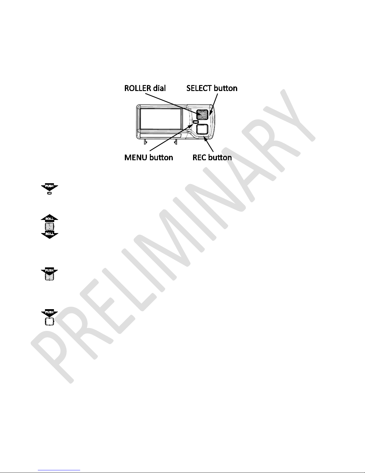
2.1 Front Side
Figure 1: G-TECH front side
•
MENU button – used to get you in and out of main menu and out of submenus
•
ROLLER dial – is the most important in navigating though the user interface. Please note that besides being able
to rotate up and down, it can also be pushed-in to select a given menu item.
•
SELECT button – is the part of the ROLLER dial. You can push-in the ROLLER dial and this action will be referred to
as SELECT button throughout this manual.
•
REC button – this is the record/replay button and it its used to let G-TECH know that you want to start a SS run or
a RR session recording. It’s also used to input Start/Finish line and segment gates in RR mode. Throughout this
manual, this button will be referred to simply as REC button.
6 G-TECH/Pro SS/RR Fanatic Manual
Page 7
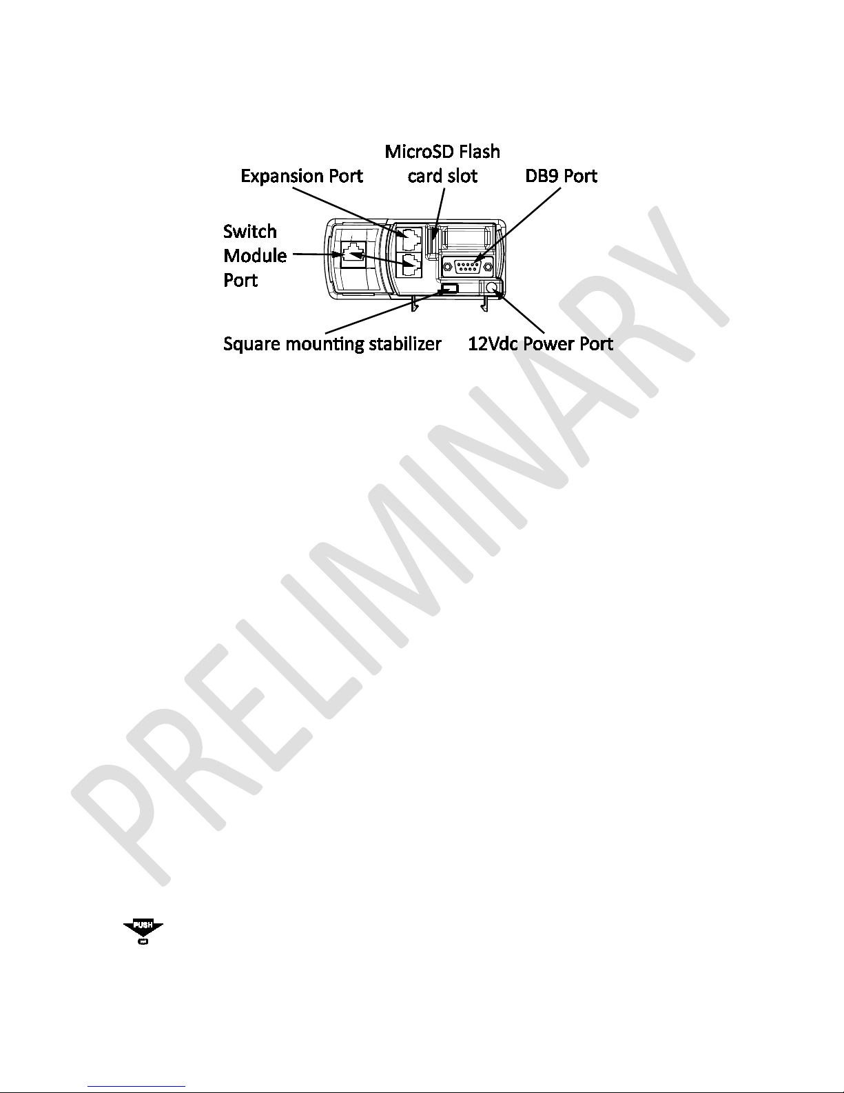
2.2 Back Side
Figure 2: G-TECH back side
• 12Vdc Power Port – plug in the supplied DC power cable into this connector
• Expansion Port – reserved for future use
• Switch Module Port – connect Switch Module to this port using supplied Ethernet cable
• DB9 Port – no user functions are available trough this port, used in G-TECH production and maintenance only
• MicroSD FLASH Card Slot – It uses “push in & push out” action just like a ball-point pen. Pushing it with a paper-
clip works well
• Square mounting stabilizer – Insert this stabilizer into the square hole in the mounting clip and snap it.
2.3 Accessories
• 12V cigarette lighter DC Power Cable – supplies power from vehicle’s accessory (cigarette lighter) plug.
The DC Power Plug has a fuse at the end that plugs into your vehicle. If the cable does not seem to provide
power, the fuse may be blown and need replacing.
To replace the fuse, unscrew the tip and replace the fuse with a standard 1A (one ampere) fuse. Fuses can
normally be purchased at any automotive parts store.
• Mounting System – used to hold your G-TECH steady in you vehicle.
For additional details, please refer to “Mounting System” on page 11.
2.4 Icons and Navigation
The G-TECH’s functionality is accessible trough its user-friendly icon interface.
Pressing the MENU button on the Main Screen brings up the main menu, as shown below:
7 G-TECH/Pro SS/RR Fanatic Manual
Page 8
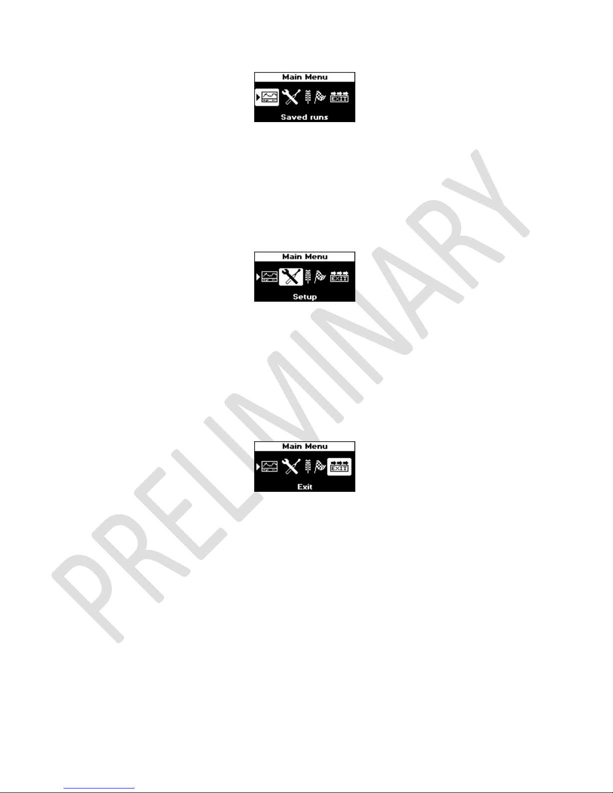
Figure 3: The G-TECH's Main Menu
The name of the menu appears in the Menu Title Bar at the top of the display (“Main Menu” in this example).
The main menu has 4 icons. The first icon is in “reverse video” because it is the active (selected) icon. Use the ROLL dial to
move amongst the different icons.
For example, moving the ROLL dial down by “one click” in Figure 3 would move the icon selection to the Setup icon, as
shown below:
Figure 4: Main Menu: "Setup" icon selected
The Setup Icon Hint in Figure 4 indicates that the selected icon represents setup items.
Use the SELECT button to make a selection. For example, to customize the G-TECH you would move to Setup icon and
then press SELECT button.
Selecting Exit icon on any menu brings you up one level. If you are on the Main Menu when you select Exit, you will be
returned to the Main Screen.
Figure 5: Main Menu: "Exit" icon selected
Moving one level up on any menu can also be accomplished by pressing MENU button. If you are on the Main Menu
when you press MENU button, you will be returned to the Main Screen. Pressing MENU button again while on Main
Screen will bring you back to Main Menu.
8 G-TECH/Pro SS/RR Fanatic Manual
Page 9
3 Quick Setup
3.1 Connecting
There are only two cables to connect on the G-TECH unit. The Switch Module is connected to Switch Module Port by
supplied short Ethernet cable. If you want to mount the Switch Module away from G-TECH unit you can use longer
straight-trough Ethernet cable to do that. Power supply is connected trough 12VDC Power Port.
For location of Switch Module Port and 12VDC Power Port, please see the image in section 2.2 on page 7.
3.2 Adjusting Local Time
G-TECH date and time are based on Coordinated Universal Time (UTC) which is extracted from GPS signal. This time code
is closely related to Greenwich Mean Time (GMT) and it has time zones defined the same way as GMT. To obtain correct
date and time you need to adjust difference between UTC and your local time.
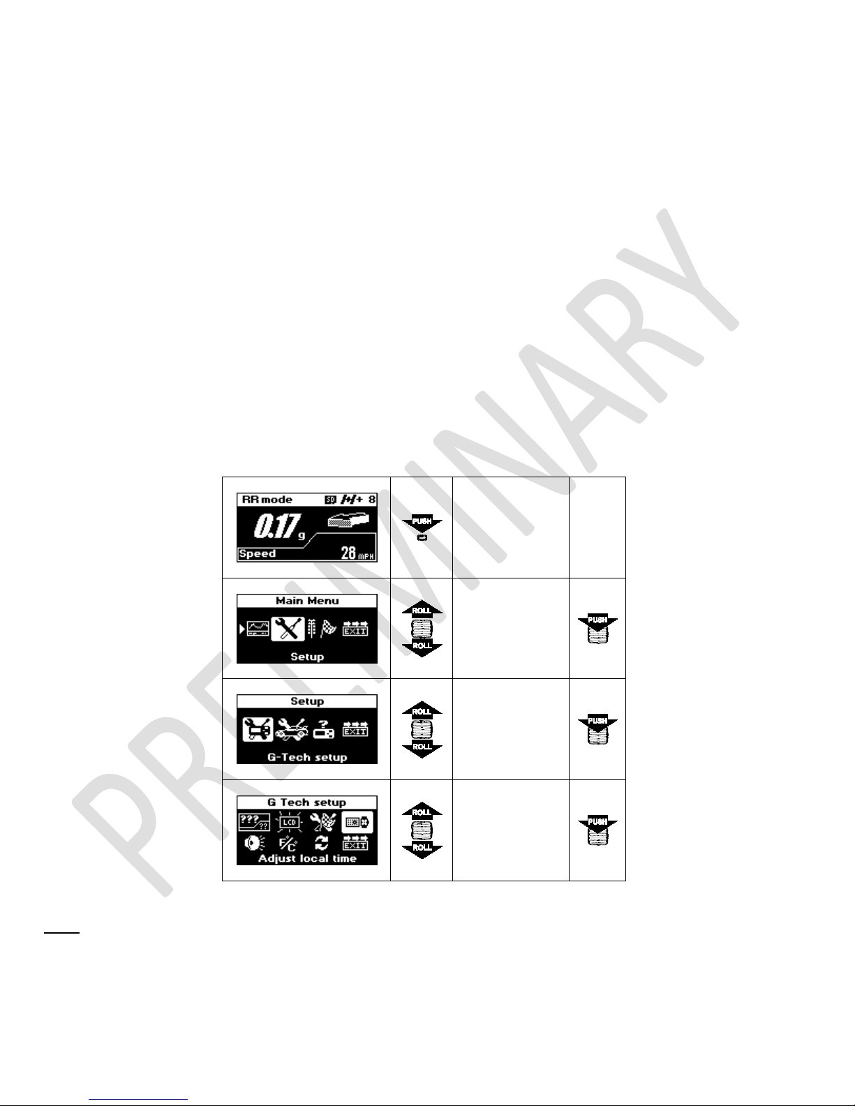
To access Adjust local time menu, follow the steps below:
Press MENU
button to enter
Main Menu
Select
Setup
Select
G-Tech Setup
Select
Adjust local
time
Note:
This setup requires that G-TECH has a valid GPS signal in order to extract UTC date and time. If that is not the case,
you will see a screen as shown below:
9 G-TECH/Pro SS/RR Fanatic Manual
Page 10
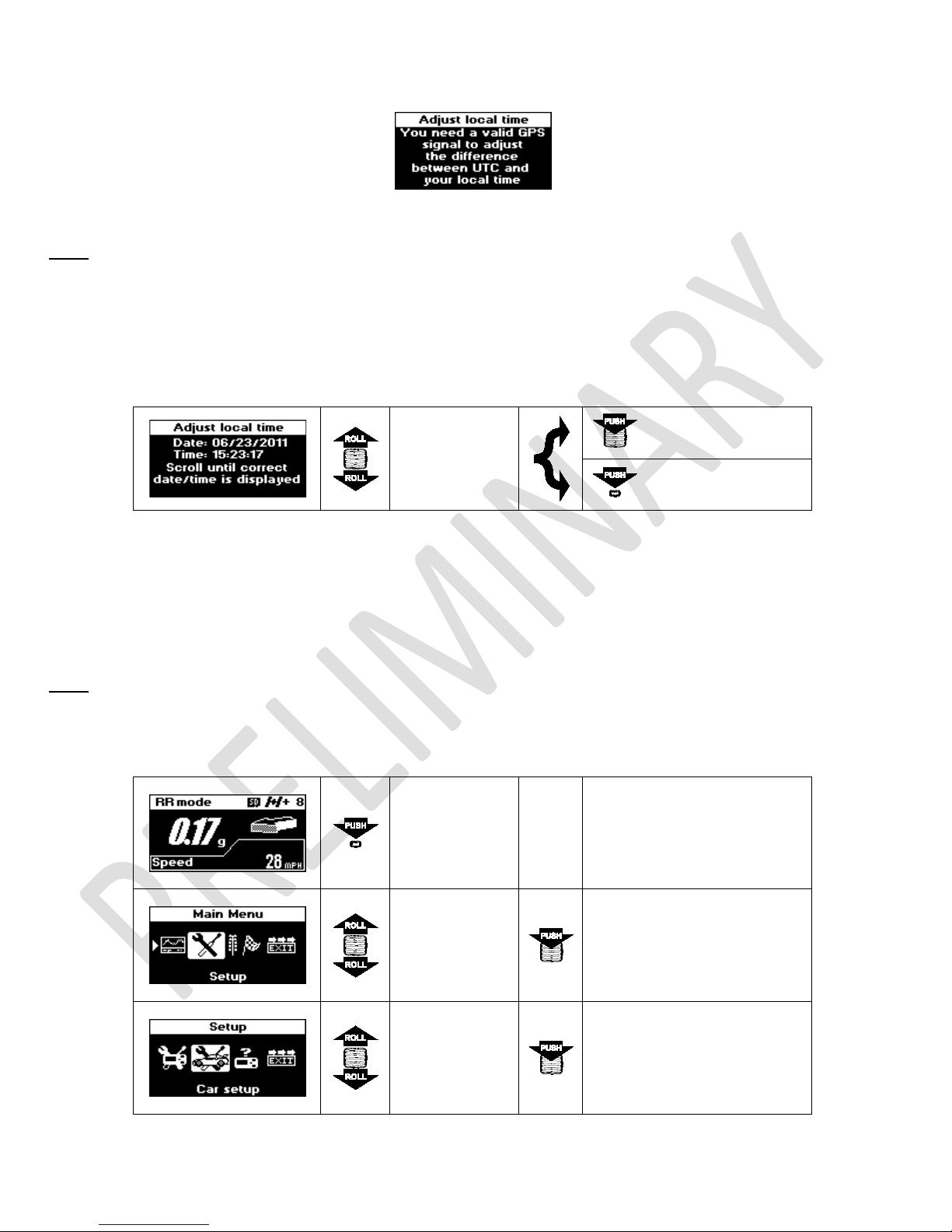
Figure 6: Adjust local time - no valid GPS signal
Note: You need to be in open space for G-TECH to acquire valid GPS signal. If you are in garage, under the large bridge
or in a tunnel, please drive your car out into open.
Once G-TECH has a valid GPS signal you will be presented with this screen, where you can use ROLL button to change
displayed time until it mach your local time.
Roll up or down
to adjust time
Confirm selection
displayed on
the screen
Cancel changes
You can adjust only hour portion of the time which corresponds to your local time zone. UTC time is extremely accurate
and it’s minutes and seconds portions are guaranteed to be correct, therefore they can’t be changed.
3.3 Car Weight
Note: Vehicle weight must be set properly in order to obtain accurate HP measurements. For help determining vehicle
weight, please see page 59 for details.
Press MENU
button to enter
Main Menu
10 G-TECH/Pro SS/RR Fanatic Manual
Select
Setup
Select
Car setup
Page 11
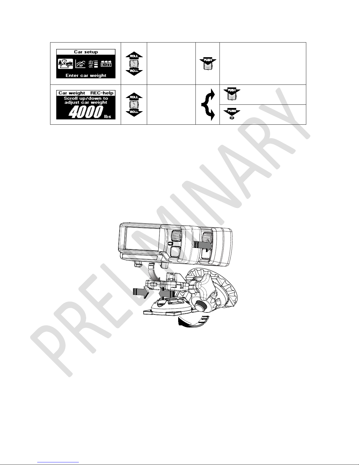
Select
Enter Car
weight
Roll to adjust
Confirm selection
car weight
Cancel changes
3.4 Mounting System
To mount the G-TECH in the clip, insert the square mounting stabilizer at the back of the G-TECH into the square hole in
the clip and snap it. To remove it, squeeze the handles and pull it out. See illustration below for details.
Switch module can be detached from G-TECH body by pushing it backward. This way you can mount it somewhere closer
to you. You will find this very useful especially when strapped in a 5-point racing harness. It uses a regular Ethernet
straight-trough (network) cable which can be purchased in any electronics store.
G-TECH can be mounted on the windshield with the suction cup or any other surface, including the dashboard by using
the three mounting screw holes or a 2” square piece of Velcro.
11 G-TECH/Pro SS/RR Fanatic Manual
Page 12
4 Everyday Driving
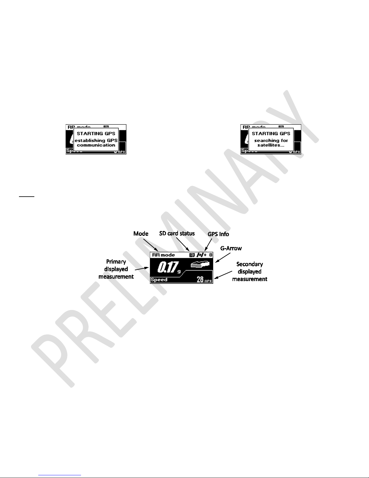
4.1 Main Screen Overview
After power-on, the G-TECH starts GPS communication (Figure 7) followed by searching for satellites (Figure 8). Until it
acquires valid GPS signal, G-TECH will keep this message on.
Figure 7: Starting GPS: establishing GPS communication
Figure 8: Starting GPS: searching for satellites...
Note:
You need to be in open space for G-TECH to acquire valid GPS signal. If you are in garage, under the large bridge
or in a tunnel, please drive your car out into open.
After acquiring valid GPS signal, G-TECH will hide “STARTING GPS” message and you will be presented with Main Screen
Figure 9: G-TECH's Main Screen
The Main Screen in Figure 9 has six main indicators:
• Mode – shows current mode of operation
• Primary displayed measurement – shows selected measurement in big numbers
• Secondary displayed measurement – shows selected measurement in smaller numbers
• G-Arrow – direction of G-Force
• GPS Info – basic information of current GPS status
• SD card status – indicates whether SD card file system is available
4.2 Mode
G-TECH Fanatic series devices come in two versions, SS and RR. The G-TECH SS Fanatic has one mode of operation, the
“SS mode” which will always be indicated on the Main Screen. If you purchased G-TECH RR Fanatic, or upgraded your G-
12 G-TECH/Pro SS/RR Fanatic Manual
Page 13
TECH SS Fanatic with SS to RR Upgrade Kit, you will be able to choose operating mode. In this case G-TECH will indicate
current mode by showing “SS mode” or “RR mode”.
For additional details about SS and RR modes, please see page 15 or page 18 respectively.
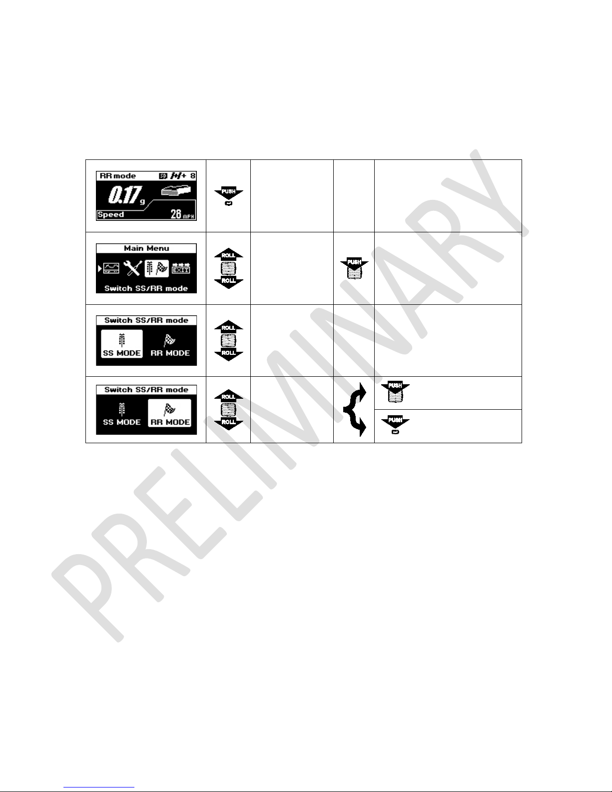
4.2.1 Mode Change
Press MENU
button to enter
Main Menu
Select
Switch SS/RR
mode
Roll up or down
to select mode
Roll up or down
to select mode
Confirm selection
Cancel changes
4.3 Primary displayed measurement
By default, primary displayed measurement indicates amount of G-force. In combination with G-Arrow it creates a Realtime G meter. Primary displayed measurement can be configured to show any of these 3 parameters: G-force, speed or
real time horsepower.
Please see page 46 for details on configuring Main Screen.
4.4 Secondary displayed measurement
By default, secondary displayed measurement indicates current speed. It can be configured to show any of these 3
parameters: Speed, G-force or real time horsepower.
Please see page 46 for details on configuring Main Screen.
13 G-TECH/Pro SS/RR Fanatic Manual
Page 14
GPS Info
Condition
Eight satellites being tracked, SBAS available
G-Arrow
G-Value
Condition
.85
Accelerating Fwd 0.85 Gs
.34
Left Turn 0.34 Gs
.28
Left Turn & Accelerating 0.28 Gs
.00
Minimal G-force
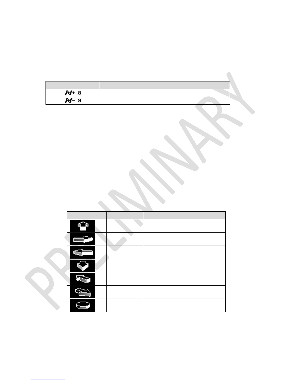
4.5 GPS Info
GPS info indicator consists of satellite icon followed by SBAS indicator and number of satellites being tracked.
G-TECH’s GPS receiver is SBAS enabled, meaning that it can provide improved performance trough integration of
external information when available. If SBAS is available, satellite icon is followed by “+” sign, otherwise by “-“ sign.
Nine satellites being tracked, SBAS unavailable
Please see page 58 for more information on SBAS.
4.6 G-Arrow
The Real-time G Meter is a combination of the G-Value and the G-Arrow. It indicates both the amount and direction of Gforce, whether your vehicle is braking, cornering, or blasting down the dragstrip.
The display is continuously updated in response to your driving, and tells you all you need to know about your vehicle’s
handling and acceleration capabilities.
The G-value indicates the amount of G-force to within a one hundredth of a G. G-Arrow indicates the direction of G-force.
Figure 10 illustrates how to read the Real-time G Meter.
Right Turn 0.75 Gs
.75
1.55
Braking 1.55 Gs
.56
Right Turn while Braking 0.56 Gs
14 G-TECH/Pro SS/RR Fanatic Manual
Figure 10: Real-time G Meter examples
Page 15
4.7 SD card status
This indicator is available only on G-TECH RR Fanatic which uses SD file system for data storage.
Display of SD card icon indicates that card is present and file system is operational.
5 Performing SS Runs
Note: G-TECH must be in SS mode to perform SS Run. For information on how to change current mode, please see page
13.
There are two types of measurements possible in SS mode, the SS Acceleration Run and HP-TQ Measurement. They
require different driving techniques so please be sure to read and understand following instructions.
5.1 SS Acceleration Run
This section describes how to measure accelerating and braking performance. With G-TECH Fanatic series this type of
measurement can be made either from stop or while car is already running.
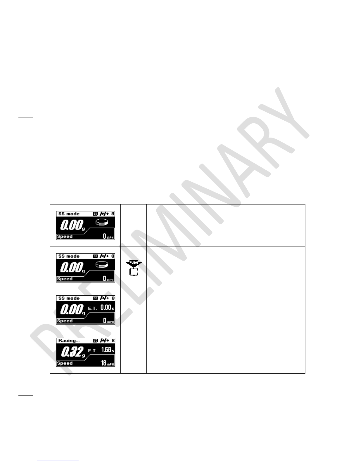
Make sure G-TECH is mounted properly, powered on, in
SS mode, GPS has a valid signal, and Main Screen is
displayed
Press REC button to activate recording
Accelerate you vehicle briskly and G-TECH will
automatically start recording. Note that E.T. clock will
start running.
Keep driving…
Note: The G-TECH requires some “oomph” to automatically start recording. If G-TECH doesn’t start timing, launch your
car with more force. G-TECH will reduce the amount of force required if you’re not starting from stop.
15 G-TECH/Pro SS/RR Fanatic Manual
Page 16
To finish the run:
• if you want to measure braking distance, brake strongly all the way to a complete stop, and wait for the
• if you do not care about braking distance, simply let off throttle and coast for about 1 second, until E.T.
• press REC or MENU button to cancel the race
E.T. clock to stop
clock stops
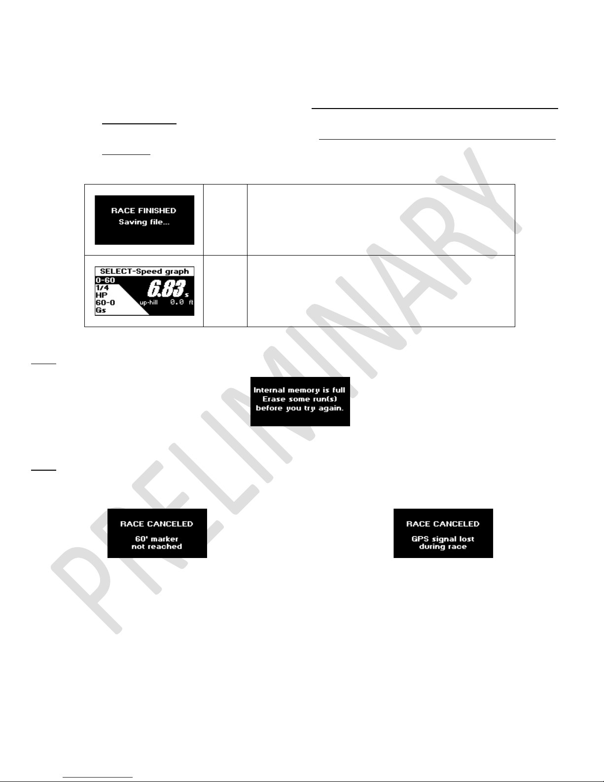
The run will be saved automatically. While the run is
being saved, the display will show “RACE FINISHED”
screen as shown here.
After saving the run, G-TECH will open it for review as
show bellow. For information on how to view and analyze
your runs, please see page 31.
Note:
If you don’t have enough free storage in internal memory, you will not be able to start the SS Run.
Figure 11: Internal memory is full
Note: If you do not travel at least 60 ft, or you loose GPS signal while recording, the run will be discarded.
Figure 12: Race too short
Figure 13: GPS lost
5.2 HP-TQ Measurement
This type of measurement requires different driving technique. For best results make sure you follow the instructions
from G-TECH.
16 G-TECH/Pro SS/RR Fanatic Manual
Page 17
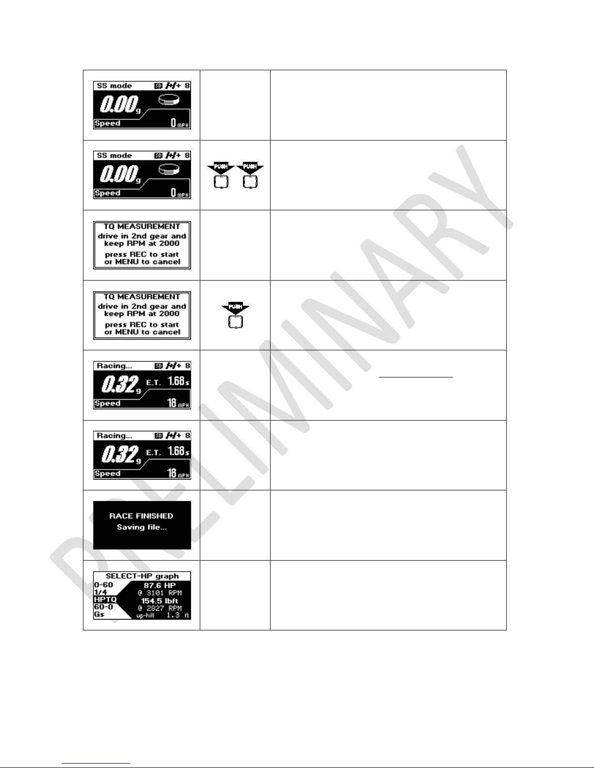
Make sure G-TECH is mounted properly, powered
on, in SS mode, GPS has a valid signal, and Main
Screen is displayed
Double-click REC button to activate recording
Start your vehicle and keep driving according to
nd
instructions. Drive in 2
at 2000 RPM.
gear and keep your engine
When you have reached 2000 RPM, press REC
button to start recording.
Step on the accelerator all the way down. Keep
driving like that until you reach redline with engine
RPMs.
If you reached redline, let the throttle off and coast
for about 1 second, until E.T. clock stops.
The run will be saved automatically. While the run
is being saved, the display will show “RACE
FINISHED” screen
17 G-TECH/Pro SS/RR Fanatic Manual
After saving the run, G-TECH will open it for review.
For information on how to view and analyze your
runs, please see page 31.
Page 18

6 Recording RR Sessions
Note: G-TECH must be in RR mode to record RR Session. For information on how to change current mode, please see
page
13.
In RR mode you can record your racing session on circular or hill-climb tracks. During the session G-TECH records your
vehicle’s position, speed, acceleration and lap times all in real time as you go.
6.1 RR Session Concepts
6.1.1 Gates
When thinking about gates, first thing you should think of is a START/FINISH line on a circular track. This line is defined by
two points, one on the leftmost side of the track and other on the rightmost side. During the race you are crossing the
START/FINISH line only in one direction. This means that START/FINISH line is orientated is in driving direction.
G-TECH specifies gates the same way. They have a direction and they are defined by two points on a map. Only difference
is that defining points usually lay outside the track, the gate is normally wider than track.
There are also two types of gates. The START/STOP gates are special because they define the start and end of the track.
On circular tracks, this is the same line. On hill-climb track these are two different gates.
Other type of gate is a segment gate, it is used to mark positions on track and divide track into segments. This way you
can measure segment times, cornering times, etc.
The START/STOP gates are defined during map recording and they can not be changed or moved. The segment gates can
be defined during map recording or you can add/remove them later when reviewing the session.
On how to change segment gates after the session, please see page 43.
6.1.2 Map
G-TECH maps are defined by START/STOP gate, optional segment gates and GPS location points representing the race
track shape. Each map has a name and default viewing orientation.
All RR Sessions are driven on maps which can be recorded during the race or reused from some previous session.
6.1.3 Map-Vicinity Automatic Recording
While in RR mode, G-TECH is constantly tracking distances to existing maps. When you approach the location of existing
map G-TECH will detect that situation and load the map in preparation for RR Session recording. If multiple maps are
found in your vicinity you will be asked to select which map you will be driving at.
With Map-Vicinity Automatic Recording you can start RR Session recording without even having to press one button. Just
drive your vehicle to the track, go over the START line and that’s it!
G-TECH will load the map as you approach the track and start recording when you cross the START line.
18 G-TECH/Pro SS/RR Fanatic Manual
Page 19

On how to enable/disable Map-Vicinity Automatic Recording, please see page 47.
6.1.4 The “Thumb” Screens
During the RR Session, every time you finish a segment, you will get “Thumbs Up” or “Thumbs Down” screen with the
amount of time gained or lost in that segment. If you made better time, the entire screen will invert, so you can sense
this with peripheral vision, without ever taking the eyes of the track.
Each thumb is filled to a certain level depending on how much time you gained or lost in that particular segment.
Completely filled thumb means that you have gained or lost more than 5 seconds.
Figure 14: Thumb up, big loss
Figure 15: Thumb up, small
loss
Figure 16: Thumb down,
small gain
Figure 17: Thumb down, big
gain
This is like heaving a race-driving instructor with you all times. Best of all, there is no need for waiting to see the
information, it’s immediate, while it’s still fresh in your mind and you know what you just did. It’s the best way to
implement incremental improvements in your driving and get faster by slowly building up speed and “picking-up” time on
the track anywhere you can. This feature will definitely make anyone a better driver.
6.2 RR Session – Circular Track
Depending on whether you’re driving on existing map or you need to record a new one (new location), RR Session
recording will be somewhat different.
6.2.1 Starting RR Session recoding
To start RR Session recording make sure you are on the Main Screen and in RR mode.
Depending on whether you are driving on new location and if Map-Vicinity automatic recording is enabled there are
three scenarios:
• driving on new location, no previous map exists
• driving on location with prerecorded map, Map-Vicinity automatic recording is disabled
• driving on location with prerecorded map, Map-Vicinity automatic recording is enabled
19 G-TECH/Pro SS/RR Fanatic Manual
Page 20

6.2.2 Driving on new location
Make sure G-TECH is mounted properly, powered on, in
RR mode, GPS has a valid signal and Main Screen is
displayed
Press REC button to initiate
RR Session recording
G-TECH will prepare itself for RR Session which may take
few seconds
When G-TECH finishes preparing for RR Session you will
be presented with this info screen
Now you need to tell G-TECH where the START/FINISH
line is. To do that, you need to press REC button when
your car is on the START/FINISH line. There are two ways
to do that:
• drive your car to the START/FINISH line, stop it there,
press REC button and hit the accelerator.
• or drive down the track, and without stopping at
START/FINISH line, press REC button at the exact
moment that you pass over the START/FINISH line.
This way you will set the first gate on this map, the
START/FINISH gate
Note:
When setting the START/FINISH gate, make sure that you approach the START/FINISH line straight forward. Also,
do not move your vehicle back and forth around START/FINISH line trying to position your car right on to it. Instead, just
drive straight forward to START/FINISH line and stop at it.
If you approach the START/FINISH line at an angle, the START/FINISH gate that you are setting will also be angled in
respect to the track. Moving your car back and forth at the START/FINISH line can cause your START/FINISH gate to be
oriented in wrong direction. In that case, G-TECH will not be able to detect when you cross START/FINISH line.
20 G-TECH/Pro SS/RR Fanatic Manual
Page 21

After setting the START/FINISH gate, G-TECH will switch to
map recording and now you need to drive the track. You
will see a screen with message as shown here.
After a few seconds message will clear from screen as
shown here
Note: If you are setting the START/FINISH gate from stop, you will have 5 seconds to accelerate your car and continue
driving down the track. If you keep your vehicle on START/FINISH line for more than 5 seconds, RR Session recording will
be aborted.
While driving the track G-TECH will show you the running lap time, current speed and G-force bar-graph.
Figure 18: Recording map, screen elements
During map recording you can place additional gates for
dividing the track into segments. To do that, just press
REC button any time. G-TECH will confirm that new gate
was accepted by displaying appropriate message as
shown on the next screen
Note: In order to prevent accidental adding of multiple gates, there is a 5 seconds guard time between two successive
gates. This restriction applies for gates added during the map recording. After the race you have an option to set
additional gates wherever you like. For details on editing gates, please see page
43.
21 G-TECH/Pro SS/RR Fanatic Manual
Page 22

Note: Your vehicle must be moving at speed grater than 5 mph for gate to be accepted. Adding gates while stopped or
moving with less than 5 mph will be ignored.
When you finish the first lap on track (cross the
START/FINISH line), G-TECH will switch from “Recording
map…” into “RACING” mode. You will also see the
message that informs you on 1
st
lap time as shown here
After few seconds message will clear, leaving just the
RACING screen as shown here.
Note:
If you just want to record map without driving the whole session, you can stop RR Session recording after the 1st
lap. In that case skip the following set of instructions and go straight to next set on stopping the RR Session recording.
G-TECH will use recorded data to create map for the track you were driving.
If you added segment gates during the map recording,
crossing over one of these gates will bring the segment
time message on screen as shown here
nd
When you finish the 2
lap on track, G-TECH will bring
up the “Thumb” screen to inform you on time you
gained or lost in the lap as shown here
If you added segment gates during the map recording,
starting from 2
will bring the “Thumb” screen with the amount of time
nd
lap, crossing over one of these gates
you gained or lost. as shown here
22 G-TECH/Pro SS/RR Fanatic Manual
Page 23

To stop RR Session recording, follow the instructions below:
To stop RR Session recording and create map from
recorded data press MENU button anytime after
completing the 1
st
lap. Dialog appears asking you to
confirm stopping of session recording
Select
YES
G-TECH starts creating map form recorded data. This
operation can take several seconds to complete
depending on the size of the map
After successfully creating map, you will have an option
to set default orientation for a new map as shown here
Select
YES
Note: Selecting NO will complete map recording and setup and jump to file system entry for this RR Session. You will not
be presented with further options for map setup, but you will be able to change them later. On how to change map
options for existing maps, please see
RR Session Review on page 37.
Selecting YES will display the recorded map asking you to
select default orientation
Use ROLLER to
rotate the map
the way you find it
most suitable
When satisfied with your
choice press SELECT to
confirm orientation
23 G-TECH/Pro SS/RR Fanatic Manual
Page 24

After setting the default orientation, you will be asked to
set a name for the map
Use ROLLER to
select YES
Use ROLLER to
change
highlighted
character
Confirm your selection by
pressing SELECT button
Pressing SELECT will set
the highlighted character
and move selection on
next one
When satisfied with entry, press REC button to save this
map under new name
After renaming the map, you will be asked to define
segments
Use ROLLER to
select YES
Confirm your selection by
pressing SELECT button
Use ROLLER to
move cursor up
and down the
track
Press SELECT to add new
gate(s)
When satisfied
with gates setup
press REC to save
your configuration
Note: Gates Editing screen has more features, like deleting specific gates, clearing all gates, etc. For additional
information on Gates Editing screen, please see page
43.
24 G-TECH/Pro SS/RR Fanatic Manual
Page 25

After setting the gates you will be given the option to
replay last session as shown here. See page 37 for more
details on RR Session review
6.2.3 Driving on prerecorded map with automatic recording enabled
Make sure G-TECH is mounted properly, powered on, in
RR mode, GPS has a valid signal and Main Screen is
displayed. Drive you vehicle to a location where you
recorded a map(s).
When you get into vicinity of map location, G-TECH will
detect that and display a screen as shown here.
Depending on whether you have one ore more maps in
vicinity of your current location, G-TECH will load the map
or inform you that multiple maps were detected.
In case of single map, it will be automatically loaded
within few seconds.
In case of multiple maps, you will have an option to
choose which map to use
If multiple maps were detected, use ROLLER to select map
you want to drive.
Use ROLLER
to select a
map
Press SELECT to confirm
your selection
25 G-TECH/Pro SS/RR Fanatic Manual
While loading a map, G-TECH will show you this screen
Page 26

After loading the map, G-TECH is ready to start recording
6.2.4 Driving on prerecorded map with automatic recording disabled
RR session as soon as you drive over the START line. You
will see a screen with scaled map and plus marker
indicating your current position
Make sure G-TECH is mounted properly, powered on, in
RR mode, GPS has a valid signal and Main Screen is
displayed. Drive you vehicle to a location where you
recorded a map(s).
When you get into vicinity of map location, press REC
You will be given a choice to record new map or drive on
existing one, as show here.
Use ROLLER
to select
YES or NO
button.
Selecting YES will load a map or
bring the map selection screen
Selecting NO will start new
map recording
26 G-TECH/Pro SS/RR Fanatic Manual
Page 27

6.3 RR Session – Hill-Climb
Hill-Climb sessions are driven on non-circular tracks. This means that every hill-climb map has a separate START and
FINISH gate defined.
6.3.1 Starting RR Session recoding
To start RR Session recording make sure you are on the Main Screen and in RR mode.
Depending on whether you are driving on new location and if Map-Vicinity automatic recording is enabled there are
three scenarios:
• driving on new location, no previous map exists
• driving on location with prerecorded map, Map-Vicinity automatic recording is enabled
• driving on location with prerecorded map, Map-Vicinity automatic recording is disabled
6.3.2 Driving on new location
Recording hill-climb session on new location is almost the same as recording a circular track session. The only difference
is that for hill-climb session you need to define separate START and FINISH gates. To do that, start session recording as
you would for circular track. To stop recording, and place the FINISH gate, double-click REC button.
To stop Hill-Climb RR Session recording and
create map from recorded data double-click
See section “Driving on new location” on page 20 for more details. Everything said there applies to Hill-Climb sessions
too. The only difference is the way you stop session recording.
MENU button anytime during the session.
6.3.3 Driving on prerecorded map with automatic recording enabled
This scenario is the same as for circular maps. See section “Driving on prerecorded map with automatic recording
enabled” on page 25 for more details.
6.3.4 Driving on prerecorded map with automatic recording disabled
This scenario is the same as for circular maps. See section “Driving on prerecorded map with automatic recording
disabled” on page 26 for more details.
27 G-TECH/Pro SS/RR Fanatic Manual
Page 28

7 Reviewing Runs
7.1 Opening Saved Run
Each G-TECH has an internal FLASH memory for saving up to twelve SS Runs. For additional storage you will need an RR
Upgrade kit, which enables the RR mode of operation and provides micro SD card interface and file system. With this
upgrade kit you can use micro SD cards for practically unlimited storage of SS Runs and RR Sessions.
7.1.1 From Internal Memory
Internal FLASH memory is used exclusively for saving SS Runs. It has a limited storage space for twelve SS Runs. You can
save your runs for later review or delete selected runs to free some space.
Note:
Internal memory is always accessible on SS units. On RR units or upgraded SS units internal memory is accessible
only if no valid micro SD card is present.
To open a saved run from internal memory
Saved runs screen appears as shown below:
Press MENU button to enter Main Menu
Use ROLLER
to select
Saved runs
option
Press SELECT to confirm
28 G-TECH/Pro SS/RR Fanatic Manual
Figure 19: Saved runs, internal memory
Page 29

Each run is represented with folder icon which can be empty or full. Selected run is shown as open folder. Name of the
selected run, with key result, is displayed at the bottom of the screen, as shown in Figure 19.
Use ROLLER
button to
select a run
Press SELECT to confirm
Use ROLLER
to select
Replay this
run
Press SELECT to confirm. This
will open the run for review.
7.1.2 From SD Card File System
SD Card File System is available only on RR units and is organized in familiar way, as folders and files. Both SS Runs and RR
Sessions are saved here if you are using a RR unit.
To open a saved SS run,
Press MENU button to enter Main Menu
Use ROLLER
to select
Saved runs
option
Press SELECT to confirm
Use ROLLER
to select
type of run
you want to
open
Press SELECT to confirm
SS runs are arranged in
folders for each date.
Use ROLLER button to
select date folder
Press SELECT to open
the date folder
29 G-TECH/Pro SS/RR Fanatic Manual
Page 30

Each run within date folder is named with time-stamp
when it was recorded. When you select a particular run,
you will get the key result for that run displayed on the
bottom of the screen as shown here
To open a saved RR Session:
Use ROLLER button to
select a run
Use ROLLER to select
RR RUNS
Press SELECT to open
the run for review
Press SELECT to
confirm
RR Sessions are arranged in map
folders which are named by the
map they represent. Use
ROLLER button to select a map
folder.
Press SELECT
to open the
map folder
Each map folder has two additional files, besides all the
date folders. One of them is called MAP.GTM and it’s used
The other file is called GATES.GTM and it’s used to
to rotate the map (see page 44).
input/edit map segments (see page 43).
30 G-TECH/Pro SS/RR Fanatic Manual
Use ROLLER button to
select date folder
The date folders contain the RR
Session files which are time-
stamped when they were
recorded. Use ROLLER button
to select session file.
Press SELECT to open
the date folder
Press SELECT
to open the
session file
Page 31

button brings up:
100-0 MPH, etc.)
7.2 SS Run Review
The run review allows you to see all the details of particular run. These details include results like:
• 0-60 MPH time
• ¼ mile E.T. and trap speed
• ¼ mile replay
• Horsepower and torque
• Intermediate mile stones, such as 60 ft time, 330 ft time, 1/8 mile time and speed, 1000 ft time
• Forward G-force measurements
There are two ways to enter the SS Run Review:
• Automatically after you have completed a run
• When you review a saved run (see Opening Saved Run on page 28)
The G-TECH remembers what type of result you most recently looked at (e.g. HP, 0-60 MPH, etc.) and brings you back to
the same result when you view a new run.
Each entry in the results menu has two functions. First, when you select an entry, the highlighted result is displayed.
Additionally, each entry has an associated graph that can be viewed by SELECT button. The title bar at the top of each
entry indicates which graph will be shown when you press SELECT button.
Use ROLLER to view the different results. Use MENU button to exit.
Figure 20 below shows the 0-60 menu as an example. In this example 0-60 mph result is 6.83 seconds, with measured
altitude difference between start and finish of 1.3 ft.
Figure 20: SS Run Review, 0-60 MPH time
Menu entry
Pressing SELECT
Graph provides: Graph is useful for:
• Measuring time to get
Graph of vehicle speed throughout the
run
from one speed to
another (e.g. 0-100
MPH, 50-70 MPH, 0-
31 G-TECH/Pro SS/RR Fanatic Manual
Real time replay with vehicle speed and
milestones times
• Viewing intermediate
milestones (e.g. 330 ft
time)
Page 32

throughout the run
•
• Estimating effects of
Graph of Horsepower output
throughout the run
wind drag on your
vehicle
• Looking at horsepower
• Measuring braking
Graph of vehicle speed vs. distance to
stop, the braking distance graph
distance
• Estimating effects of
different tires and
settings
See how strong your car
was pulling (accelerat-
Graph of G-force throughout the run
ing) throughout the run
• See how well your car
brakes
• Detecting wheelspin
• Getting a “dyno plot”
Graph of Horsepower and Torque vs.
RPM
for your vehicle
• Determining the best
shift-point
7.2.1 Speed graph
The Speed graph provides you with a graph of speed throughout the run.
You can use this graph to measure:
• time from one speed to another speed (e.g., 0-50 MPH, 40-60 MPH, etc.)
• time to accelerate from 0 to a certain speed, and brake to 0 again (e.g., 0-100-0 test)
• time to brake to halt from a particular speed (e.g., 60-0 braking time)
You will see a graph such as the one shown in Figure 21. Of course the shape of the curve, as well as the numbers and
milestones, will be different for your vehicle.
32 G-TECH/Pro SS/RR Fanatic Manual
Figure 21: Speed graph
Page 33

Use ROLLER to move the cursor on the graph. As you move the cursor, the current speed and elapsed time indicators are
updated to match the cursor position.
Each tick mark on the horizontal axis marks a 1-second difference. Each tick mark on the vertical axis marks a 10 MPH
difference.
A plus sign (+) marks a 10 MPH change. Whenever you move the cursor past a plus sign, the numbers on the bottom of
the graph are updated to reflect the time to get to that speed from 0 MPH.
Note:
The speed milestone indicator does not change until the cursor rolls over a different 10 MPH marker.
Note: See “Error! Reference source not found.” on page Error! Bookmark not defined. for detailed information on
using this graph
7.2.2 Real-time replay
Real-time replay provides you with a graph of speed throughout the run just as the speed graph, but instead 10 MPH
marks on the plot, it has a milestones marks. In order to give you the feel and excitement of the run, the graph is
replayed in real-time. This means that if you did a 15-second run, it will take 15 seconds to draw the replay.
Note:
To finish the replay quickly, rather than in real-time, simply press the SELECT button while graph is being drawn.
Once the graph is fully drawn, you will see a graph such the one shown in Figure 22.
Note:
Your graph will look different due to your driving style and vehicle.
Figure 22: Real-time replay
Use ROLLER to move cursor along the plot. As cursor moves, the speed value and time stamp value adjust to reflect the
values at the cursor position.
Each tick mark on the horizontal axis represents 1 second. Each tick mark on the vertical axis represents 10 MPH.
You will see a plus sign (+) on the graph at each place where a milestone occurred. When you move the cursor over a
milestone marker, the milestone region will be updated with the name of the milestone and its timestamp.
33 G-TECH/Pro SS/RR Fanatic Manual
Page 34

Note: You must move the cursor over a milestone (from either direction) to update the milestone region. If you move the
cursor near another milestone, but not over it, the milestone region will not
be updated.
7.2.3 Horsepower graph
The horsepower graph shows net and total horsepower throughout a run. Net horsepower is what is actually used to
accelerate the vehicle. The total horsepower has air drag and other losses included, so it should approximate the real
engine power at any time.
This is not the optimal graph for analyzing horsepower. It will show artifacts around shift points that are due to factors
other than engine horsepower. It will also show the increasing effect of aerodynamic drag on the vehicle and the
corresponding lower “net horsepower” as the speed increases.
The graph resembles the one shown in Figure 23. Of course the shape of the curve, as well as the numbers and ranges,
will be different for your vehicle.
Figure 23: Horsepower graph
Use ROLLER to move cursor. As cursor moves, the horsepower and time values are adjusted to follow the cursor.
Note the “dips” in measured horsepower on the graph. As soon as you push in the clutch to shift, you decelerate (due to
aerodynamic drag), and there is no net horsepower delivered to the wheels.
7.2.4 Braking distance graph
You can use the G-TECH to measure 60-0 MPH braking distance. To measure your vehicle’s 60-0 braking distance:
• perform an acceleration run as usual (you do not need to perform a full ¼ mile, but make sure you reach at least
60 MPH)
• when you are done accelerating, brake hard all the way to a stop
Note: If you do not brake to a complete stop at the end of your run, and wait for the E.T. clock to stop, you will not get a
good 60-0 MPH braking distance measurement.
The 60-0 result screen will be similar to one shown below in Figure 24 but the shape of the curve and displayed values
will look different due to the different driving style and different vehicle.
34 G-TECH/Pro SS/RR Fanatic Manual
Page 35

Figure 24: Braking distance graph
Use ROLLER to move the cursor along the plot. As the cursor moves, the current speed and distance to stop are updated
to match the cursor position.
Each tic mark on vertical axis marks 10 MPH difference. A plus sign (+) marks a 10 MPH change. Whenever you move the
cursor past a plus sign, the numbers on the bottom of the graph are updated to reflect the distance from that speed to a
stop.
7.2.5 G-force graph
The G-force graph shows the measured G-force throughout a run. Larger G values indicate stronger acceleration.
The graph is useful for seeing how hard your vehicle was pulling when it was accelerating (positive Gs) and how hard it
was decelerating while braking (negative Gs).
Figure 25:G-force graph
Use ROLLER to move the cursor. The G-force and timestamp always pertain to the current cursor position. Each tic mark
on the horizontal axis marks 1 second. Each tic mark on the vertical axis marks 0.1 G of acceleration.
Positive G-force means the vehicle is accelerating. Negative G-force means the vehicle is decelerating (shifting, coasting,
braking).
The brief dips in plot are shift points. When you shift, you temporarily remove power, and this causes the vehicle to
decelerate briefly, until you re-engage the next gear.
35 G-TECH/Pro SS/RR Fanatic Manual
Page 36

In a very powerful vehicle, or a traction-limited vehicle, you may also notice dips in acceleration that are not due to shifts.
These dips are due to more power being applied to the wheels that can be handled. The net result is that the wheels spin
and the vehicle does not accelerate much.
The large dip you see at the end of the graph is a hard braking at the end of the run. Notice that at the end of the graph,
Gs can show zero value. This is because vehicle came to a stop. Hence there is no acceleration or deceleration.
7.2.6 Horsepower and Torque graph
One of the most exciting features of the G-TECH is its ability to measure and graph your vehicle’s horsepower and torque
against an RPM range.
The G-TECH’s HP-TQ plot provides you with a graph of horsepower and torque throughout an RMP range in a single gear.
This is the “dyno plot” that everyone is accustomed to seeing.
Note: In order for you to get consistent HP & TQ graphs, there is a special driving technique. This technique is different
than the driving technique you would use for a quick ¼ mile. Please refer to “
HP-TQ Measurement” on page 16 for more
information on optimal technique for performing horsepower runs.
You will see a graph such the one shown in Figure 26. Of course the shape of the curve, as well as the numbers and
ranges, will be different for your vehicle.
Figure 26: HP & TQ graph
You will notice a few things about Figure 26. The horsepower curve is drawn in a thick line, the torque curve is drawn
with a thin line. Also the peak horsepower and torque values are marked on the graph.
Use ROLLER to move cursors for HP and TQ. As cursor moves, the RPM, HP and TQ values are updated to reflect the
current cursor position.
36 G-TECH/Pro SS/RR Fanatic Manual
Page 37

7.3 RR Session Review
The RR session review allows you to see all the details of particular session. These details include results like:
• best lap time
• lap to lap timing
• segment times
• forward acceleration and braking throughout a session
• lateral acceleration throughout a session
• session replay with map view
There are two ways to enter the RR Session Review:
• Automatically after you have finished recording a session
• When you open a saved session from SD file system (please see section 7.1.2 on page 29)
When you open the session for review, you will se a screen as show below:
Figure 27: RR Session Review, splash screen
This screen shows you the name of the map with date and time of session. Also you can see what lap was the fastest and
what was the actual time for that lap. You can close this message by pressing REC button and continue with RR replay. To
bring this message back on the screen, press REC button any time during the replay.
Figure 28: RR Session Review, replay started
After closing the initial screen, the RR replay starts and you will see a screen similar to the on in Figure 28. The top of the
screen shows longitudinal and lateral accelerations, current speed and current lap number. The central part of the screen
shows the map on which this session was driven. Your vehicle is represented with plus sign (+) cursor that moves along
the track. Top left corner, just below the top line holds the replay speed icon.
37 G-TECH/Pro SS/RR Fanatic Manual
Page 38

Initially the RR Session Review is in real-time replay, indicated by replay speed icon in the shape of standard play sign. You
can change the replay speed to 2, 5 or 10 times the real-time replay. Also you can pause the replay, or make it go in
reverse. Reverse replay also has 2, 5 and 10 times replay speed. Replay speeds faster than real-time are indicated by
standard fast-forward icons. Paused replay has a standard pause sign for replay speed icon.
Figure 29: RR Session Replay,
fast-forward x5
Figure 30: RR Session Replay,
pause
Figure 31: RR Session Replay,
fast-reverse x10
Use ROLLER to change the replay speed. Turning ROLLER up will increase the replay speed, and turning it down will
decrease the replay speed. Once you are in real-time replay speed, turning ROLLER down will set replay to pause. Turning
ROLLER down again, will change replay-speed to reverse. Additional turns down will set replay speed to 2, 5 and 10 times
real-time in reverse respectively.
One of the great things in RR replay is the LAP JUMP mode. It allows you to jump laps from any point on the map. This is
very useful when comparing different laps. You can see what you did differently in each lap, what was your speed in one,
and what in other.
To get into LAP JUMP mode just push SELECT button once. The replay will stop and replay speed icon will change to LAP
JMP indicating LAP JUMP mode. Now you can jump into another lap at the same track position by turning the ROLLER
button. This way you can quickly compare segments from different laps or see how many Gs you pulled at a particular
corner in different laps. To get out of the LAP JUMP mode simply press SELECT button again. This way you don’t have to
replay all the laps to find the one you are looking for.
While in LAP JUMP mode, each time you jump, the lap time message will appear. This message shows you what is the
current lap, time you had in that lap and whether that is the best lap in session. See images below for details.
Figure 32: RR Session Replay, lap jump
Figure 33: RR Session Replay, lap jump, best lap
38 G-TECH/Pro SS/RR Fanatic Manual
Page 39

During a replay, every time the cursor goes over two successive gates you will get the segment time defined by those
gates. Similarly, each time the cursor crosses the start gate, you will see a message with lap number and lap time. See
images below for details. Segment and lap times are displayed only when crossing the gates in forward direction.
Figure 34: RR Session Replay,
segment time
Figure 35: RR Session Replay,
lap time
To exit RR Session Replay, press MENU button at any time.
7.4 Deleting a Run
7.4.1 Deleting from internal memory
To delete a run
Press MENU button to enter Main Menu
Use ROLLER
to select
Saved runs
option
Figure 36: RR Session Replay,
best lap time
Press SELECT button to confirm
39 G-TECH/Pro SS/RR Fanatic Manual
Use ROLLER
to select the
run you
want to
delete
Use ROLLER
to select
Erase this
run
option
Press SELECT button to confirm
Press SELECT button to confirm
Page 40

Use ROLLER
to select
YES
or NO
Press SELECT button to confirm
7.4.2 Deleting from SD Card File System
SD Card File System is available on RR units and it’s organized as folders and files. Both SS Runs and RR Sessions are saved
here. To delete a SS run,
Press MENU button to enter Main Menu
Use ROLLER to
select Saved
runs option
Press SELECT button to
confirm
Use ROLLER to select type of run you want to delete
Use ROLLER to
select type of
run you want to
delete
Press SELECT button to
confirm
Assuming you selected to delete a SS Run you will see a
screen with date folders as shown here. SS Runs are
organized in those folders according to the date they were
recorded. You have an option to delete the whole date
folder with all the runs in it, or to delete a single run.
To delete a
folder, use
ROLLER to select
which one you
want to delete
Double-click SELECT
button to confirm
40 G-TECH/Pro SS/RR Fanatic Manual
Page 41

Use ROLLER to
select YES or NO
Press SELECT button to
confirm
To delete a
specific run,
select date
folder using
ROLLER
Use ROLLER to
select a run you
wan to delete
Use ROLLER to
select YES or NO
Press SELECT button to
confirm
Double-click SELECT
button to confirm
Press SELECT button to
confirm
To delete an RR session
Use ROLLER to
select type of
run you want to
delete
Press SELECT button to
confirm
If you selected to delete a RR run you will see a screen with
map folders as show here. RR session are organized in map
folders, based on map they represent. Within map folders
are date folders with actual session recordings, a and two
additional files, MAP.GTM and GATES.GTS file.
To delete or
rename map
folder, use
ROLLER to select
one of them
Double-click SELECT
button to confirm
41 G-TECH/Pro SS/RR Fanatic Manual
Page 42

Use ROLLER to
select Erase this
map option
Use ROLLER to
select YES or NO
Press SELECT button to
confirm
Press SELECT button to
confirm
Note:
Erasing the map folder will also delete all date folders within together with MAP.GTM and GATES.GTS files.
Effectively this will remove this map and all associated sessions from SD card.
To delete a
specific run, select
map folder using
ROLLER
Press SELECT button to
confirm
When you open a map folder you will see a screen similar
to one here. This particular map folder contains two date
folders and two additional files, MAP.GTM and GATES.GTG.
To delete a date
folder, and all
sessions it
contains, select
one using ROLLER
Use ROLLER to
select YES or NO
Double-click SELECT
button to confirm
Press SELECT button to
confirm
To delete a single
session file, use
ROLLER to select
date folder
Use ROLLER to
select session file
Press SELECT button to
confirm
Double-click SELECT
button to confirm
42 G-TECH/Pro SS/RR Fanatic Manual
Page 43

Use ROLLER to
select YES or NO
7.5 Gates editing
To edit gates, go to saved RR sessions and open the map folder.
Use ROLLER
to select
GATES.GTG
file
Use ROLLER
to move
cursor along
the track
Press SELECT button to
Press SELECT button confirm
confirm
Press SELECT button to set new
gate in position of the cursor.
Repeat these steps to place
additional gates on the track.
Repeat the step above to place additional gates on the
track.
To delete a gate, use ROLLER to move the cursor backward.
As soon as cursor crosses the existing gate, G-TECH will ask
you to delete that gate as shown below
Once you have set all the segments the way you want, press
REC button to save that configuration.
43 G-TECH/Pro SS/RR Fanatic Manual
Page 44

G-TECH will ask you to confirm as shown here.
If you selected NO in previous dialog, you will be given the
option to start all over again as shown here. Selecting YES
will restart gates editing and all the gates entered so far will
7.6 Map rotation
To rotate a map, go to saved RR sessions and open the map folder.
be deleted.
Use ROLLER
to select
MAP.GTM
file
Press SELECT button to confirm
Use ROLLER
to rotate
the map to
preferred
position
Press SELECT button to confirm
new setting
Use ROLLER
to rotate
the map to
preferred
position
Press MENU button
to cancel map rotation
Note:
This new orientation will apply to RR session review, map selection screen and all other screens that need to
display a map
44 G-TECH/Pro SS/RR Fanatic Manual
Page 45

7.7 Renaming the map
To rename a map, go to saved RR sessions and open the map folder.
Use ROLLER
to select
MAP.GTM
file
Double-click SELECT button
to bring up
next menu
Use ROLLER
to select
Rename this
map option
Press SELECT button to confirm
On top of the screen is the current name of the map which
you wan to change. In the central part of screen you can see
a row of eight letters and numbers, with a highlight on
selected character.
Use ROLLER
to change
selected
character
When satisfied with your selection,
press SELECT button to move
highlight to next character. Use this
to set all the letters for map name.
Press REC button to confirm renaming the map
If map folder with entered name already exists, G-TECH will
Press MENU button to cancel map rename
display a message as shown here.
In that case press MENU button to remove this message
from screen and enter a different name for the map.
45 G-TECH/Pro SS/RR Fanatic Manual
Page 46

by using ROLLER at any time.
8 Additional Features
8.1 Configuring Main Screen
During everyday driving, Main Screen can show three real time measurements, G-force, speed and horsepower. Each of
these measurements can be shown as primary or secondary displayed value. To configure the Main Screen displayed:
Press MENU button to enter Main Menu
Use ROLLER
to select
Setup option
Press SELECT button to confirm
Use ROLLER
to select G-
Tech setup
option
Use ROLLER
to select
Main screen
option
Use ROLLER to select which measurements you want on
Main Screen. Bottom of the screen shows
your current selection.
In this example, G-force for primary and speed for
secondary displayed measurement.
There is also a “Rotation with roller” option which enables
changing the displayed measurements from Main Screen
Press SELECT button to confirm
Press SELECT button to confirm
Press SELECT button to confirm
46 G-TECH/Pro SS/RR Fanatic Manual
Press MENU button to cancel
Page 47

8.2 Changing Map-Vicinity Automatic Recording setting
To change Map-Vicinity Automatic Recording setting
Use ROLLER
to select
Setup option
Use ROLLER
to select G-
Tech setup
Use ROLLER
to select
RR setup
Use ROLLER
to select
Automatic
recording
Press MENU button to enter Main Menu
Press SELECT button to confirm
Press SELECT button to confirm
option
Press SELECT button to confirm
options
Press SELECT button to confirm
Use ROLLER
to select YES
or NO
Press SELECT to confirm
Press MENU to cancel
8.3 Upgrading SS to RR
To upgrade your G-TECH from SS to RR you will need an RR Upgrade Kit. This kit will automatically convert your G-TECH
into the RR model. Installation is very simple, just open the back of the unit and insert the memory expansion card (no
tools required). Kit includes memory expansion card, micro SD card and micro SD card USB reader (no PC drivers needed).
47 G-TECH/Pro SS/RR Fanatic Manual
Page 48

8.4 Moving Runs To SD Card File System
When using the G-TECH without microSD card (SS unit, or RR unit with no microSD card inserted) you can record only the
SS runs. Those runs are saved to internal memory.
If you have some runs in internal memory and you power-up the G-TECH with microSD card inserted, G-TECH will offer to
move the runs as shown below:
Use ROLLER
to select YES
G-TECH will start copying the runs
When copying is done, G-TECH will inform you with this
Press SELECT button to confirm
message
8.5 HP Losses
When doing a horsepower calculation, the G-TECH can directly measure only the time and acceleration of your vehicle.
To calculate horse power, you need to tell G-TECH the exact weight of your vehicle. With those data it is possible to
calculate the net horsepower. That’s the power actually used to move your vehicle, sometimes referred to as wheel
horsepower (whp) or effective horsepower.
Note:
Always perform horsepower and torque measurements on flat road. As indicated above, the G-TECH calculates
horsepower by measuring vehicle’s acceleration. Driving on a sloped road can increase or reduce acceleration when
driving downward or upward. If you can’t use the perfectly flat road, make two measurements in both direction, than
average the results. This way slope errors will cancel each other.
The net horsepower is lower than actual power produced by your engine. That’s because some of the power produced by
engine is lost on aerodynamic drag and various losses in the drive train. Where does that lost power goes? The
aerodynamic losses shed some power on moving the air around vehicle, and overcoming the drag. The drive train losses
include the rolling resistance of tires, friction losses in differentials, friction loses in the gear box, etc. At the end, all of the
losses are converted into heat and sound/pressure waves.
48 G-TECH/Pro SS/RR Fanatic Manual
Page 49

G-TECH can include all those losses in horsepower calculation, and give you the total horsepower for your engine,
sometimes referred to as indicated or gross horsepower (theoretical capability of the engine). To do that, G-TECH needs
to know you vehicle’s frontal area, coefficient of drag and percents of power lost in drive train.
Even if you don’t know the exact values of these parameters for you car, you can still get valuable results. For example,
your total horsepower might not be exactly the same as factory number, but you can still see the difference before and
after the modifications you made on your vehicle. Also, you can always use the net horsepower as your benchmark, since
this is the actual power used to move your vehicle.
To change HP Losses settings,
Press MENU button to enter Main Menu
Use ROLLER
to select
Setup option
Press SELECT button to confirm
Use ROLLER
to select Car
setup option
Press SELECT button to confirm
Use ROLLER
to select HP
losses option
Press SELECT button to confirm
You will have two options, to set aerodynamic losses
49 G-TECH/Pro SS/RR Fanatic Manual
Or to set drive train losses
Page 50

8.5.1 Aerodynamic losses
To enter this setup,
Use ROLLER
to select
Aerodynamic
losses option
Press SELECT button to confirm
Use ROLLER
to select
Frontal area
option
Press SELECT button to confirm
8.5.2 Drive train losses
From HP losses menu,
Use ROLLER
to adjust
your vehicle
frontal area
Press SELECT button to
confirm
Press MENU button to
cancel
Use ROLLER
to select
Coefficient
of drag
option
Use ROLLER
to adjust
coefficient of
drag
Press SELECT button to confirm
Press SELECT button to
confirm
Press MENU button to
cancel
Use ROLLER
to select
Drive train
losses option
Press SELECT button to confirm
50 G-TECH/Pro SS/RR Fanatic Manual
Use ROLLER
to adjust
percents of
drive train
losses
Press SELECT button to
confirm
Press MENU button to
cancel
Page 51

8.6 Enabling/Disabling Key Click
To change Key Click setting
Use ROLLER
to select
Setup option
Use ROLLER
to select G-
Tech setup
Use ROLLER
to select
Use ROLLER
to select YES
Press MENU button to enter Main Menu
Press SELECT button to confirm
Press SELECT button to confirm
option
Sound
option
or NO
Press SELECT button to confirm
Press SELECT to confirm
Press MENU to cancel
8.7 LCD settings
These settings are used to customize your G-TECH display the way you like. You can find them under the Display menu.
Press MENU button to enter Main Menu
to select
Press SELECT button to confirm
51 G-TECH/Pro SS/RR Fanatic Manual
Use ROLLER
Setup option
Page 52

Use ROLLER
to select G-
Tech setup
option
Press SELECT button to confirm
Use ROLLER
to select
Display
setup option
Press SELECT button to confirm
This is the Display menu for customizing your G-TECH
display
Use ROLLER
to select US
Press SELECT to confirm
or METRIC
option
Press MENU to cancel
8.7.1 Adjust color
This menu gives you an option to play with each individual segment of the color RED, GREEN and BLUE. Starting from
Display menu
Use ROLLER
to select
Adjust color
option
Press SELECT button to confirm
It’s set-up as an equalizer so that you can quickly get the
color you like. As you enter the equalizer screen you are
automatically adjusting RED color first, indicated by an
upright arrow as shown here
52 G-TECH/Pro SS/RR Fanatic Manual
Press SELECT
button to
select RED
value
ROLLER to
change
intensity
Use
RED
Press
SELECT
to
confirm
Page 53

Use ROLLER to select other color
Repeat the process as described for RED color
Press MENU button to leave this menu and confirm your
settings
8.7.2 Preset colors
This menu allows you to choose from a few predetermined colors like pure, red, green, blue, amber and yellow. Starting
from Display menu
Use ROLLER
to select
Choose
preset color
option
Press SELECT button to confirm
53 G-TECH/Pro SS/RR Fanatic Manual
Use ROLLER to select preset color
Press SELECT button to confirm selection. Display will
change color immediately to reflect your selection.
Press MENU button to exit this screen.
Page 54

8.7.3 Adjust contrast
This option sets the contrast of the LCD. In some extreme temperature instances the LCD might need contrast
readjustment. Starting from Display menu
Use ROLLER to select Adjust
contrast option
Use ROLLER to set contrast
for LCD. Contrast will
change immediately to
reflect your selection.
Press SELECT
Press SELECT
button to
confirm
button to
confirm
8.8 US or metric mode
This menu allows you to choose between displaying data in a US (Imperial) or Metric mode. All the logs that were
recorded in US mode are automatically converted to the Metric mode and vice versa.
Press MENU button to enter Main Menu
54 G-TECH/Pro SS/RR Fanatic Manual
Use ROLLER
to select
Setup option
Use ROLLER
to select G-
Tech setup
option
Use ROLLER
to select US
or metric
mode option
Press SELECT button to confirm
Press SELECT button to confirm
Press SELECT button to confirm
Page 55

Use ROLLER
to select US
or METRIC
option
Use ROLLER
to select US
or METRIC
option
Press SELECT to confirm
Press MENU to cancel
8.9 Reset options
This menu will give you two options, to reset your G-TECH to factory defaults and to format SD card (for RR units).
Resetting to factory defaults will delete all of your SS runs stored into internal FLASH. It will also reset all the custom
settings that you have made and revert them to factory defaults. Formatting SD card will erase all data on it, all the SS
runs and all the RR sessions.
Note:
Be careful when using this options, you may accidentally delete some files you didn’t intended to.
8.9.1 Format SD Card
Press MENU button to enter Main Menu
55 G-TECH/Pro SS/RR Fanatic Manual
Use ROLLER
to select
Setup option
Use ROLLER
to select G-
Tech setup
option
Use ROLLER
to select
Reset
options
Press SELECT button to confirm
Press SELECT button to confirm
Press SELECT button to confirm
Page 56

Use ROLLER
to select
Format SD
card
option
Press SELECT button to confirm
Use ROLLER
to select YES
While formatting, progress bar will fill up until formatting
Press SELECT button to confirm
is done.
When formatting is completed, press SELECT button to
confirm and return to Format SD card menu.
Note:
Do not power-off your G-TECH while formatting is in progress. Doing so will cause SD file system errors. If
formatting gets interrupted for whatever reason, repeat the process.
8.9.2 Reset to factory defaults
In some cases you may want to restore the G-TECH to the condition it was when it was shipped from the factory.
Restoring to factory defaults will clear out all the configuration information and runs stored in internal flash memory. For
RR units, runs and session stored on micro SD card will not be affected.
Note:
Resetting the G-TECH to Factory Defaults resets nearly all the information stored in the G-TECH. Perform this step
only if you are sure that you want to delete all configuration information and SS runs stored in internal memory.
Press MENU button to enter Main Menu
Use ROLLER
to select
Setup option
Press SELECT button to confirm
56 G-TECH/Pro SS/RR Fanatic Manual
Page 57

Use ROLLER
to select G-
Tech setup
option
Press SELECT button to confirm
Use ROLLER
to select
Reset
options
Press SELECT button to confirm
Use ROLLER
to select Set
to factory
defaults
option
Press SELECT button to confirm
Use ROLLER
to select YES
While G-TECH is performing the reset to factory defaults
you will see a message as shown here
Press SELECT button to confirm
Once the procedure is done, G-TECH will reset itself and
you will see the Main Screen.
57 G-TECH/Pro SS/RR Fanatic Manual
Page 58

9 Additional Info
9.1 About GPS
Here you can find some facts and explanations regarding the GPS. Although complete understanding of these terms is not
necessary in order to use G-TECH, these facts provide valuable information on this subject.
9.1.1 Update rate
G-TECH uses high speed GPS receiver with 10Hz update rate to increase accuracy and overall performance. This gives us
capability to monitor car’s speed and position more closely, ten times better than with average GPS receivers which
usually have an update rate of once per second.
To illustrate importance of update rate, imagine your self driving a car down the track, but not being able to control your
vehicle continuously. Instead, you are allowed do adjust speed and steering only once per second. Sure, you wouldn’t
have much control over your vehicle, unless you are driving really slow. Now try to visualize the same situation but being
able to react ten times per second. This is a very different situation, it would actually allow you to drive quite well.
9.1.2 Sensitivity
The built-in GPS receiver in G-TECH is of latest generation which has an exceptional sensitivity. Coupled with ceramic
patch antenna it gives G-TECH unrivaled performance in receiving GPS signal.
We have decided to utilize the fact that G-TECH is not a tiny hand-held, battery-powered device which has to keep it’s
size/weight and power consumption at bare minimum. Instead, we decided to choose GPS receiver by it’s performance,
rather by it’s power consumption. Also the patch antenna we are using is far superior than chip antennas used in mobile
phones and similar devices. This kind of antenna is unpractical for mobile phones because of it size and weight, so phone
manufacturers are forced to go with miniature chip antennas with inferior performance.
9.1.3 SBAS System
Another key feature for improving GPS accuracy is built-in SBAS (Satellite Based Augmentation System) support. It
improves GPS accuracy trough the integration of additional correction data from dedicated geostationary satellites.
There are several SBAS systems, but none of them has a global coverage. For example, WAAS covers north America,
EGNOS covers Europe, MSAS is operational in Japan and parts of Asia while GAGAN is used in India. G-TECH addresses
this problem by using GPS receiver capable of incorporating correction information from all of these systems, WAAS,
EGNOS, MSAS and GAGAN.
9.2 About File System
G-TECH’s micro SD card interface is capable of working with several SD card types, including the high capacity SDHC cards.
Also, it can use cards formatted with both FAT16 and FAT32 file systems.
58 G-TECH/Pro SS/RR Fanatic Manual
Page 59

But there are several things you should know about SD cards and file system. There are many devices capable of using
and formatting SD cards, like personal computers, mobile phones, cameras, camcorders, etc. Formatting includes creating
complex structures and setting several parameters which compose file system. Because of that, there are some
differences between formatting on various devices. Some devices will format cards using FAT16 or FAT32 file system.
They can also use different cluster sizes to suit their needs.
To ensure best performance, format your card using G-TECH. This will set appropriate file system and cluster size to
optimize file system operations.
9.3 About Vehicle Weight
In order to calculate meaningful horsepower measurements, you must provide an accurate value for your vehicle’s
weight.
In this manual, the term “vehicle weight” refers to all the weight that is supported by the vehicle’s tires (including the
tires themselves). So this includes the driver’s body weight, fuel weight, tools, fast food wrappers, etc.
If you are fortunate enough to have access to an accurate vehicle scale, go ahead and weight the vehicle as it would be
equipped at the track (i.e., with you in it, the correct amount and type of fuel in the tank, etc.).
Some tracks even have scales available for weighting your vehicle. Also, some towns have dumps or refuse collection
areas with large scales that you may be able to use. Moving companies may have vehicle scales as well.
If you can’t weight your vehicle, estimate it. Use the manufacturer’s data to obtain vehicle weight (from the Owner’s
Manual or the internet). Then adjust the weight based on the difference between your car as it was stock, and as it is now
(Have you added heavier stereo? Have you removed the spare tire?). Don’t forget to include your own body weight and
the fuel as well.
You do NOT want to use the Gross Vehicle Weight Rating (GVWR) value that is provided in the vehicle door jamb as the
actual vehicle weight.
GVWR is the fully-loaded vehicle weight with passengers. Thus, GVWR is always higher than actual vehicle weight, and if
you enter GVWR instead of actual vehicle weight, your horsepower numbers will be artificially inflated.
A rough rule of thumb to estimate your vehicle weight from the GVWR exists, but don’t rely on it being too accurate.
Again, this is very ROUGH rule of thumb… each manufacturer calculates GVWR in its own way…
The rule of thumb is to take the passenger capacity of the vehicle (e.g., 5 for a mid-sized sedan) and subtract from the
GVWR 180lbs for each missing person.
Example: Suppose GVWR = 4200 lbs, vehicle capacity is 5 people, but we have only a driver. Thus there are 4 missing
passengers, which means we subtract 4x180 lbs. The value 4200 lbs – 720 lbs = 3480 lbs. Thus you would enter 3480 lbs
into the G-TECH for vehicle weight.
59 G-TECH/Pro SS/RR Fanatic Manual
Page 60

10 Appendix A – Menu map
60 G-TECH/Pro SS/RR Fanatic Manual
 Loading...