

Page 1

Powerwall 2 AC Installation Manual
with Backup Gateway
Page 2
For the latest Powerwall installation documents in all supported languages, visit:
www.tesla.com/support/powerwall.
To secure the full 10-year product warranty, be sure to register Powerwall online.
Warning: Read this entire document before installing or using Powerwall. Failure to
do so or to follow any of the instructions or warnings in this document can result in
electrical shock, serious injury, or death, or can damage Powerwall, potentially
rendering it inoperable.
PRODUCT SPECIFICATIONS
All specifications and descriptions contained in this document are verified to be
accurate at the time of printing. However, because continuous improvement is a goal
at Tesla, we reserve the right to make product modifications at any time.
The images provided in this document are for demonstration purposes only.
Depending on product version and market region, details may appear slightly
different.
ERRORS OR OMISSIONS
To communicate any inaccuracies or omissions in this manual, send an email to:
energy-pubs@tesla.com.
ELECTRONIC DEVICE: DO NOT THROW AWAY
Proper disposal of batteries is required. Refer to your local codes for disposal
requirements.
MADE IN THE USA
©2017 TESLA, INC. All rights reserved.
All information in this document is subject to copyright and other intellectual property rights
of Tesla, Inc. and its licensors. This material may not be modified, reproduced or copied, in
whole or in part, without the prior written permission of Tesla, Inc. and its licensors. Additional
information is available upon request. The following are trademarks or registered trademarks
of Tesla, Inc. in the United States and other countries:
TESLA
TESLA MOTORS
POWERWALL
All other trademarks contained in this document are the property of their respective owners
and their use herein does not imply sponsorship or endorsement of their products or services.
The unauthorized use of any trademark displayed in this document or on the product is
strictly prohibited.
Page 3

TABLE OF CONTENTS
IMPORTANT SAFETY INSTRUCTIONS .......................................................................................................................... 2
1. Registering Powerwall ............................................................................................................................................... 5
2. Specifications ............................................................................................................................................................... 5
Powerwall Electrical Specifications ........................................................................................................................................................................ 5
Powerwall Environmental Specifications ............................................................................................................................................................. 5
Powerwall Mechanical Specifications .................................................................................................................................................................... 5
Backup Gateway Electrical Specifications .......................................................................................................................................................... 6
Backup Gateway Environmental Specifications ............................................................................................................................................... 6
Backup Gateway Mechanical Specifications ...................................................................................................................................................... 6
3. Site Requirements ....................................................................................................................................................... 7
Powerwall Physical Requirements ........................................................................................................................................................................... 7
Powerwall Dimensions and Space Requirements ............................................................................................................................................ 8
Powerwall Temperature Requirements ................................................................................................................................................................ 8
Powerwall Installation Requirements ..................................................................................................................................................................... 9
Backup Gateway Installation Requirements ....................................................................................................................................................... 9
4. Installation Instructions ........................................................................................................................................... 10
Powerwall Box Contents ............................................................................................................................................................................................ 10
Backup Gateway Box Contents .............................................................................................................................................................................. 10
Required Tools ................................................................................................................................................................................................................ 10
Required Supplies.......................................................................................................................................................................................................... 10
Step 1. Plan the Installation Site ................................................................................................................................................................................ 11
Step 2. Transport and Unpack Powerwall .......................................................................................................................................................... 12
Step 3. Anchor the Powerwall Mounting Bracket .......................................................................................................................................... 14
Step 4. Prepare Powerwall for Mounting ............................................................................................................................................................ 21
Step 5. Mount Powerwall on the Bracket .......................................................................................................................................................... 23
Step 6. Prepare the Backup Gateway for Mounting .................................................................................................................................... 25
Step 7. Install a Circuit Breaker in the Backup Gateway .............................................................................................................................27
Step 8. Mount the Backup Gateway .................................................................................................................................................................... 28
Step 9. Connect Powerwall and the Backup Gateway ............................................................................................................................... 30
Step 10: Make AC Power Connections ............................................................................................................................................................... 34
Step 11. Close the Wiring Compartments and Turn On the System ..................................................................................................... 37
Step 12. Commission the Backup Gateway and Verify System Operation ....................................................................................... 37
Step 13. Finish Installation and Register the System.................................................................................................................................... 38
Troubleshooting ............................................................................................................................................................................................................ 38
Technical Support ........................................................................................................................................................................................................ 39
Maintenance .................................................................................................................................................................................................................... 39
Wiring Reference .............................................................................................................................. 40
Powerwall Inverter Adjustable Settings ................................................................................... 42
Powerwall Inverter Short Circuit Information ......................................................................... 44
1
Page 4
IMPORTANT SAFETY INSTRUCTIONS
SAVE THESE IMPORTANT SAFETY INSTRUCTIONS
This manual contains important instructions for the Tesla Powerwall 2 AC and Backup
Gateway that must be followed during installation and maintenance of the system.
Powerwall and Backup Gateway installation and service require knowledge of high voltage
electricity and should only be performed by Tesla Certified Installers. Tesla assumes no liability
for injury or property damage due to repairs attempted by unqualified individuals or a failure
to properly follow these instructions. These warnings and cautions must be followed when
using Powerwall and the Backup Gateway.
Symbols Used
These symbols indicate important safety information in this guide or on the equipment:
WARNING: indicates a hazardous situation which, if not avoided, could result in injury
or death.
CAUTION: indicates a hazardous situation which, if not avoided, could result in minor
injury or damage to the equipment.
NOTE: indicates an important step or tip that leads to best results, but is not safety or damage
related.
REFER TO OPERATING INSTRUCTIONS: indicates that user should refer to
operating or installation instructions before proceeding.
RISK OF ELECTRIC SHOCK: indicates components that present risk of electrical
shock.
CAUTION, RISK OF ELECTRIC SHOCK, ENERGY STORAGE TIMED
DISCHARGE. Discharge time is 5 minutes from de-energization.
BIDIREDTIONAL TERMINAL: Indicates location of combined input/output connector
on the equipment.
PROTECTIVE CONDUCTOR TERMINAL: Indicates location of grounding connection
on the equipment.
2 Powerwall Installation Manual
Page 5
General Information
WARNING: Read this entire document before installing or using Powerwall. Failure to do
so or to follow any of the instructions or warnings in this document can result in electrical
shock, serious injury, or death, or can damage Powerwall, potentially rendering it inoperable.
WARNING: A battery can present a risk of electrical shock, fire, or explosion from vented
gases. Observe proper precautions.
WARNING: Powerwall installation must be carried out only by Tesla Certified Installers
who have been trained in dealing with high voltage electricity.
WARNING: Powerwall is heavy. Use of lift equipment is recommended.
WARNING: Use Powerwall only as directed.
WARNING: Do not use Powerwall if it is defective, appears cracked, broken, or otherwise
damaged, or fails to operate.
WARNING: Before beginning the wiring portion of the installation, ensure that Powerwall
is switched off, and open any associated circuit breakers and disconnect switches (if
applicable for the installation).
WARNING: Do not attempt to open, disassemble, repair, tamper with, or modify
Powerwall. Powerwall and its components are not user serviceable. Batteries in Powerwall are
not replaceable. Contact the Tesla Certified Installer who installed the system for any repairs.
WARNING: To protect Powerwall and its components from damage when transporting,
handle with care. Do not impact, pull, drag, or step on Powerwall. Do not subject Powerwall to
any strong force. To help prevent damage, leave Powerwall in its shipping packaging until it is
ready to be installed.
WARNING: Do not insert foreign objects into any part of Powerwall.
WARNING: Do not expose Powerwall or its components to direct flame.
WARNING: Do not install Powerwall near heating equipment.
WARNING: Do not immerse Powerwall or its components in water or other fluids.
3
Page 6
CAUTION: Do not use solvents to clean Powerwall, or expose Powerwall to flammable or
harsh chemicals or vapors.
CAUTION: Do not use fluids, parts, or accessories other than those specified in this
manual, including use of non-genuine Tesla parts or accessories, or parts or accessories not
purchased directly from Tesla or a Tesla-certified party.
CAUTION: Do not place Powerwall in a storage condition for more than one (1) month, or
permit the electrical feed on the Powerwall to be severed for more than one (1) month,
without placing Powerwall into a storage condition in accordance with Tesla’s storage
specifications.
CAUTION: Do not paint any part of Powerwall, including any internal or external
components such as the exterior shell or casing.
CAUTION: Do not connect Powerwall directly to photovoltaic (PV) solar wiring.
CAUTION: When installing Powerwall in a garage or near vehicles, keep it out of the
driving path. If possible, install Powerwall on a side wall and/or above the height of vehicle
bumpers.
Environmental Conditions
WARNING: Install Powerwall in a location that prevents damage from flooding.
WARNING: Operating or storing Powerwall in temperatures outside its specified range
might cause damage to Powerwall.
WARNING: Do not expose Powerwall to ambient temperatures above 60°C (140°F) or
below -30°C (-22°F).
CAUTION: Ensure that no water sources are above or near Powerwall, including
downspouts, sprinklers, or faucets.
CAUTION: Ensure that snow does not accumulate around Powerwall.
4 Powerwall Installation Manual
Page 7
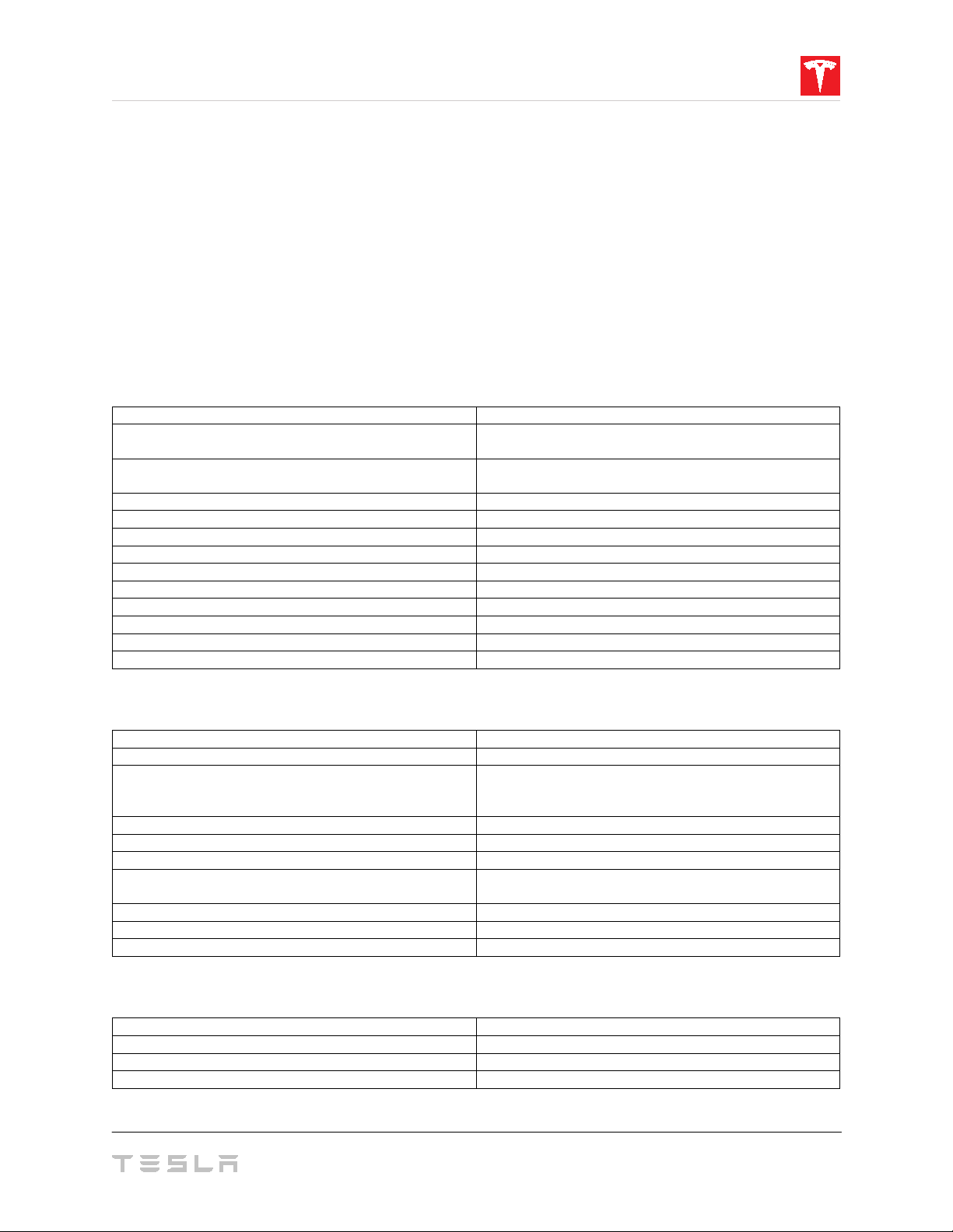
1. Registering Powerwall
Energy1
13.5 kWh
AC Voltage (Nominal)
208 V, 220 V, 230V,
100/200 V, 120/240 V
AC Voltage (Nominal) and
Maximum Continuous Current
120 V, 208 V, 240 V: 24 A
100 V, 200 V, 220 V, 230 V: 25 A
Frequency (Nominal)
50/60 Hz
Real Power, continuous
5 kW (charge and discharge)
Real Power, peak (10 s)
7 kW (discharge only)
Apparent Power, continuous
5.8 kVA (charge and discharge)
Apparent Power, peak (10 s)
7.2 kVA (discharge only)
Power Factor Range
-1 to 1
Overvoltage Category
Category III
Max Supply Fault Current
10 kA
Max Output Fault Current
32 A rms
Round Trip Efficiency (Beginning of Life)1
> 90%
Operating Temperature2
-20°C to 50°C (-4°F to 122°F)
Operating Humidity (RH)
Up to 100%, condensing
Storage Conditions (up to 12 months)
-20°C to 30°C (-4°F to 86°F)
Maximum Altitude
3000 m (9843 ft)
Noise Level @ 1 m
< 40 dBA at 30°C (86°F)
Enclosure Type
NEMA 3R
Ingress Rating
IP67 (battery and power electronics)
Wet Location Rating
Yes
Pollution Degree Rating
PD3
Seismic Rating
AC156, IEEE 693-2005 (high)
Height
1150 mm (45.3 in)
Width
755 mm (29.7 in)
Depth
155 mm (6.1 in)
Weight
125 kg (276 lbs)
Tesla Powerwall comes with a warranty whose term depends on the connection of Powerwall
to the Internet.
To secure the full 10-year warranty for Powerwall, it must be reliably connected to the Internet
to allow remote firmware upgrades from Tesla. If an Internet connection is not established or is
interrupted for an extended period, and Tesla is unable to contact the owner, the warranty
may be limited to 4 years. To ensure that the owner can receive the full 10-year warranty,
register the Powerwall by visiting www.tesla.com/support/powerwall.
For more information, refer to the Powerwall Warranty for your region at www.tesla.com.
2. Specifications
Powerwall Electrical Specifications
1
Values provided for 25°C (77°F), 3.3 kW charge/discharge power.
Powerwall Environmental Specifications
Up to 95% RH, non-condensing
State of Energy (SoE): 25% initial
IP56 (wiring)
2
Performance may be de-rated in extreme ambient temperatures.
Powerwall Mechanical Specifications
5
Page 8

Disconnect Current
200 A
Overcurrent Protection Breaker3
100-200 A
Overvoltage Category
Category III
AC Meter
Revenue grade
Operating Temperature
-20°C to 50°C (-4°F to 122°F)
Operating Humidity (RH)
Up to 100%, condensing
Maximum Altitude
3000 m (9843 ft)
Enclosure Type
NEMA 3R
Ingress Rating
IP44
Pollution Degree Rating
PD3
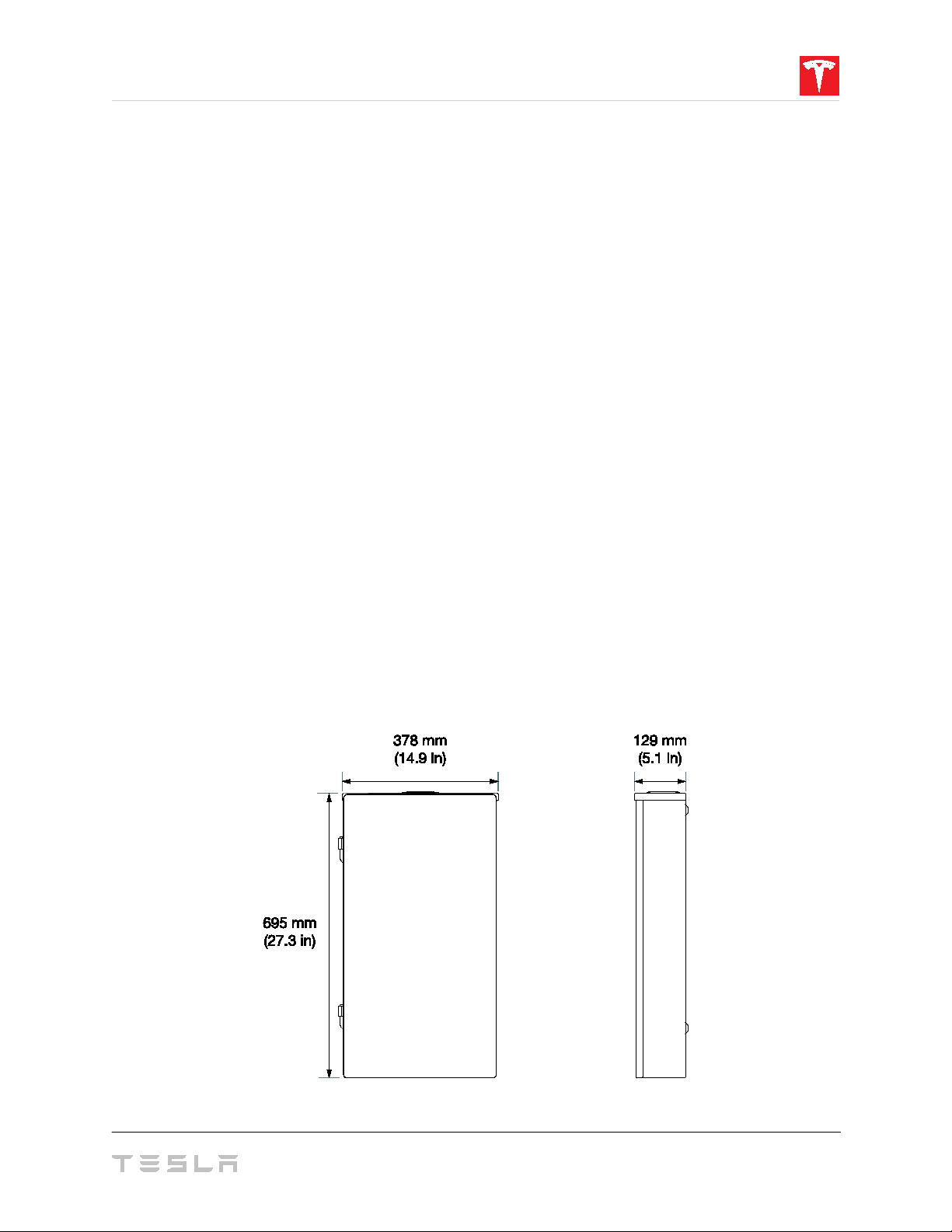
Height
691 mm (27.2 in)
Width
378 mm (14.9 in)
Depth
129 mm (5.1 in)
Weight
16 kg (36 lbs)
Backup Gateway Electrical Specifications
3
Optional
Backup Gateway Environmental Specifications
Backup Gateway Mechanical Specifications
6 Powerwall Installation Manual
Page 9
3. Site Requirements
Powerwall Physical Requirements
Powerwall can be mounted on a floor or wall. When floor-mounted, it must also be anchored
to an adjacent wall. In both types of installation, the wall must be capable of supporting the full
weight of Powerwall and its mounting hardware. The wall must extend to all edges of the
system, allowing no access to the back of the unit once it is mounted.
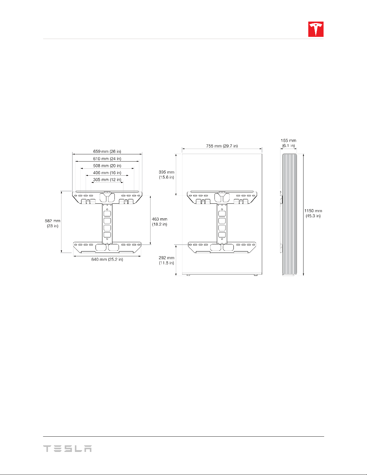
Powerwall includes a mounting bracket (Fig. 1) that supports the unit in both floor- and wallmount configurations, and includes shims to level the unit in floor-mount configurations. Do
not use other hardware to anchor Powerwall to the wall or floor.
Figure 1: Powerwall 2 Mounting Bracket Dimensions
Powerwall requires adequate clearance for installation, cabling, and airflow. Do not mount any
other objects within the clearance space (Fig. 2), except those explicitly required by the
installation (for example, conduit, a junction box, or an electrical disconnect, depending on
local installation codes). Do not install anything above Powerwall that limits access to the unit
or that might fall and damage the unit. Do not mount Powerwall horizontally or upside down.
NOTE: Powerwall has a pump and fan that enable Powerwall to maintain ideal battery
temperature. They produce a gentle hum during operation, comparable to a typical
refrigerator. The noise level depends on the ambient temperature and the power level of
operation. Consider these noise levels when choosing where to install Powerwall.
7
Page 10
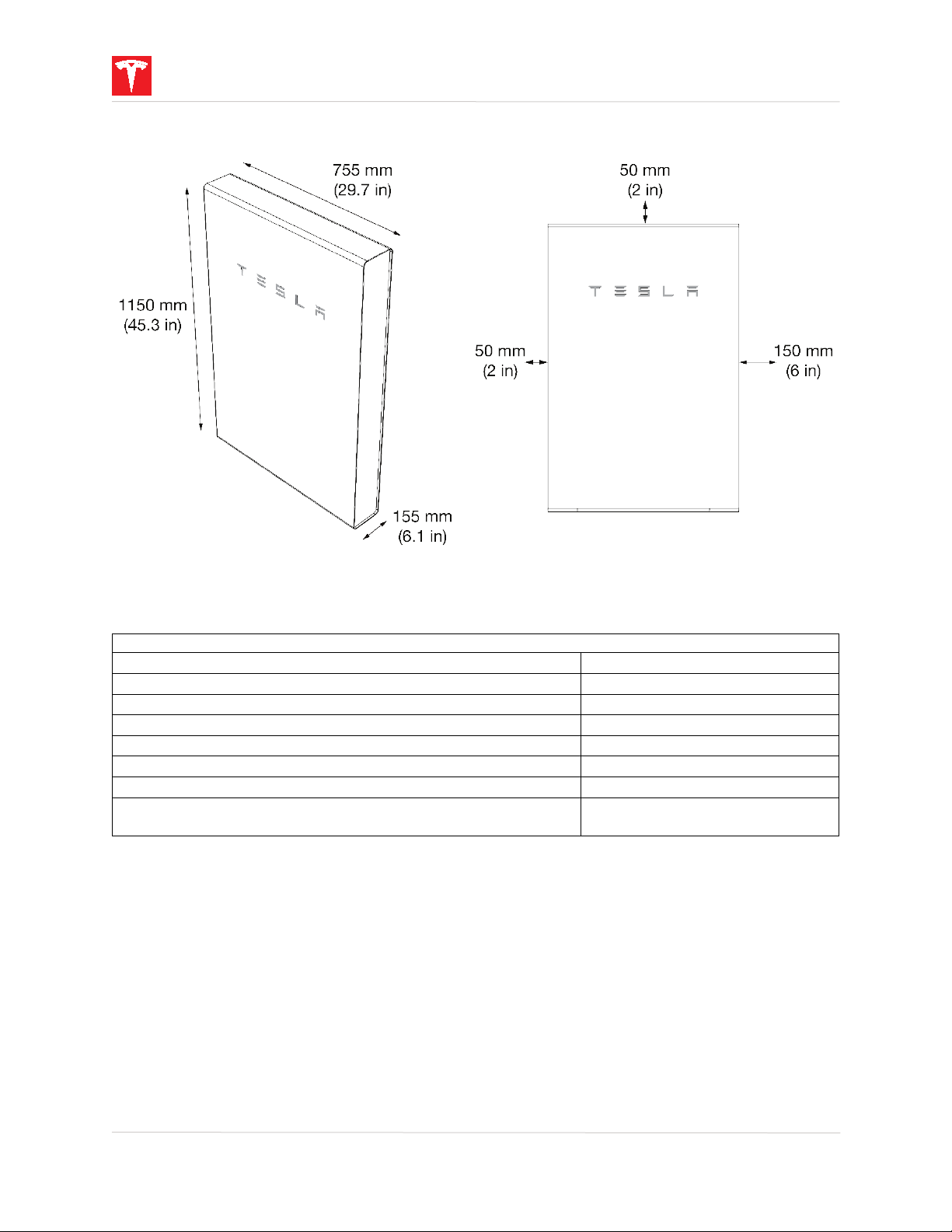
Powerwall Space Requirements
Minimum lateral wall space
960 mm (38 in)
Minimum clearance from left side (air intake)
50 mm (2 in)
Minimum clearance from right side (air exhaust)
150 mm (6 in)
Minimum clearance above single Powerwall
50 mm (2 in)
Minimum clearance above side-by-side Powerwalls
300 mm (12 in)
Minimum clearance between side-by-side Powerwalls
250 mm (10 in)
Maximum height above ground
1 m (3.3 ft) to bottom of unit
Maximum slope
+/ – 2° side-to-side
+/– 5° front-to-back
Powerwall Dimensions and Space Requirements
Figure 2: Powerwall 2 Dimensions and Space Requirements
Powerwall Temperature Requirements
Powerwall is capable of charging and discharging within the full ambient temperature range
listed in the Specifications section. At the high and low ends of the temperature range,
Powerwall may limit charge or discharge power based on battery cell temperature to improve
battery lifespan.
Installation in full sun raises the temperature inside the enclosure above ambient temperature.
This temperature rise is not a safety risk, but may impact battery performance. To optimize
performance, avoid installing Powerwall in locations that are exposed to the sun for extended
periods.
Do not install Powerwall in locations with sustained high or low temperatures. The average
ambient temperature over the system's life should be between 0°C and 30°C (32°F and 86°F).
8 Powerwall Installation Manual
Page 11
Powerwall Installation Requirements
Powerwall comes with a separate Backup Gateway and power meter to enable integration
with solar systems and the electrical grid. The Backup Gateway communicates with the
system by means of wireless and wired connections. Wiring and conduit (where required)
must be provided by the installer. Where conduit is required, the installation must comply with
local codes and UL514B requirements.
AC disconnect and interconnection requirements between the Powerwall system and the
electrical panel are subject to local codes. Ensure that the installation meets local disconnect
and interconnection requirements.
All U.S. and Canada electrical installations must be done in accordance with local codes and
the National Electric Code (NEC) ANSI/NFPA 70 or the Canadian Electrical Code CSA C22.1.
When Powerwall is installed in a dwelling unit, a smoke alarm should be installed in the same
room as the Powerwall, in accordance with local building and fire codes.
All installations must conform to the laws, regulations, codes, and standards applicable in the
jurisdiction of installation.
Backup Gateway Installation Requirements
The Backup Gateway should be wall-mounted and can be configured for cable entry at the
top, bottom, or sides of the enclosure. It requires adequate clearance for installation and
cabling or conduit. Wiring and conduit (where required) must be provided by the installer.
Where conduit is required, the installation must comply with local codes and UL514B
requirements.
The Backup Gateway should be mounted vertically, in the orientation shown below. Do not
mount the Backup Gateway enclosure horizontally or upside down.
All installations must conform to the laws, regulations, codes, and standards applicable in the
jurisdiction of installation.
Figure 3: Backup Gateway Dimensions
9
Page 12

4. Installation Instructions
Powerwall Box Contents
• Powerwall 2 AC unit
• Mounting bracket
• Accessory bag containing:
o (1) 3-pin AC power harness (600 V, 90 deg C)
o (4) wirenuts for AC power connections
o (1) 4-pin terminal block connector (black) for connection to Backup Gateway
o (1) 4-pin terminal block connector (green) for connection to additional Powerwalls
o (1) T20 Torx driver bit
o (1) 1-inch insulation bushing for conduit entry to Powerwall
o (2) shims for leveling floor-mounted units
o (1) Safety Instructions document
• On the outside of the box: printed Tesla
Backup Gateway Box Contents
• Backup Gateway Enclosure
• Neurio Meter Kit
• Powerwall 2 AC Owner’s Manual
Battery Emergency Response Guide
(ERG)
Required Tools
• Personal protective equipment (safety glasses, gloves, protective footwear)
• Drill and drill bit for drilling pilot holes in mounting surface
• Torque screwdriver with 1/4-inch bit holder (for the provided T20 Torx bit)
• Large (5 mm) flathead driver bit (for ground bar)
• Small (2 mm) flathead screwdriver (for wiring connector spring terminals)
• Torque wrench with 5/15-inch Allen bit (for Backup Gateway power connections)
• Wire strippers/cutters for 0.2
• Installation tools (level, stud sensor, tape measure, pencil, painter’s tape, flashlight)
• Lift equipment capable of lifting and supporting 125 kg (276 lbs)
• Ratcheting strap to secure Powerwall to lift equipment
WARNING: Powerwall is heavy. Wear appropriate personal protective equipment (such as gloves
and protective footwear) when handling the unit. Only a sufficient number of trained movers should lift
Powerwall. Use of lift equipment is recommended.
2
mm
to 120 mm2 (24 AWG to 250 kcmil) wires
Required Supplies
• Mounting bracket hardware (see “Step 3: Anchor the Powerwall Mounting Bracket”)
• Conduit fitting or cable gland (depending on local electrical requirements)
• Conduit or raceway (depending on local electrical requirements)
• Minimum 300 V rated 4-conductor shielded copper (Cu) cable (for communication connection
between Powerwall and the Backup Gateway)
• Minimum 600 V, 90 deg C rated copper (Cu) cable (for power connections to Powerwall and the
Backup Gateway)
• Conduit adapter (if necessary for cable entry into Powerwall wiring compartment)
• Siemens HS-style conduit hub (for entry into the top of the Backup Gateway enclosure)
10 Powerwall Installation Manual
Page 13

Step 1. Plan the Installation Site
Maximum
Cable Length
The installation location for Powerwall must accommodate placement of the Backup Gateway
and meet all conditions described above in “Site Requirements.” In addition, consider the
following points when choosing where to install Powerwall.
Wall mounting: Choose a wall capable of supporting the full weight of Powerwall, with one of
the following characteristics: wood studs at regular intervals, plywood sheeting of sufficient
thickness, solid concrete or masonry, or metal studs of sufficient gauge.
Floor mounting: Choose a level surface adjacent to a wall space that meets all the
requirements for wall mounting described above. Make sure the area is isolated from hazards
that may damage the unit, such as vehicle traffic or flooding.
Cable entry: Determine whether cables will be routed into Powerwall from the side or from the
back of the unit. With side cable entry, a conduit fitting or cable gland must be used to seal
the entry into the wiring compartment. With back cable entry, a wire cover should be used to
seal the entry into the wiring compartment.
NOTE: If you mount Powerwall on a wall with studs spaced 24 in (610 mm) apart, cable entry
from the back of Powerwall may be blocked.
Backup Gateway configuration: Determine whether cable entry into the Backup Gateway will
be from the top, bottom, or side. When cable entry is from the bottom half of the enclosure,
the back panel of the unit must be removed and rotated 180 degrees.
NOTE: For cable entry at the top of the Backup Gateway enclosure, an HS-style hub should be
used in order to maintain enclosure ingress protection.
Electrical service connection: The Backup Gateway is service-entrance rated, and can be
located between the service entry and the main electrical panel. If overcurrent protection is
required, a circuit breaker can be added to the Backup Gateway at the service entry. The
Backup Gateway can accommodate two different circuit breaker sizes: 100/125A, and
150/200A.
Cable gauge and length: Powerwall requires cable connections to the Backup Gateway,
electrical service panel(s), and an Internet router. Position Powerwall, the Backup Gateway,
and other electrical components to minimize cable lengths, based on local code requirements.
Cable Type Connection Cable Gauge
Power Powerwall to electrical panel 5-8 mm2 (10-8 AWG) 45 m (150 ft)
Power Backup Gateway to electrical panel 16–120 mm2 (6 AWG-250 kcmil) [Local Code]
2
Communication Powerwall to Backup Gateway
2 twisted pairs, 1.5 mm
Communication Backup Gateway to wireless router CAT5 45 m (150 ft)
(24-16 AWG)
- or -
CAT5
50 m (165 ft)
15 m (50 ft)
11
Page 14
Conduit or raceway: Calculate the amount and size of conduit or raceway needed for the
installation, based on fill limits and local code requirements. If you are using conduit, an
adapter may be required between the entry into the Powerwall wiring compartment and the
conduit.
Step 2. Transport and Unpack Powerwall
NOTE: Powerwall is heavy. Wear appropriate personal protective equipment (such as gloves
and protective footwear) when handling the unit. Only a sufficient number of trained movers
should lift Powerwall. Use of lift equipment is recommended. For more information, refer to
Powerwall 2 Transportation and Storage Guidelines
1. Keep Powerwall in its box until ready for installation. Store the box flat on its back (front
facing up) during transport. The box can be carried in any orientation to the job site.
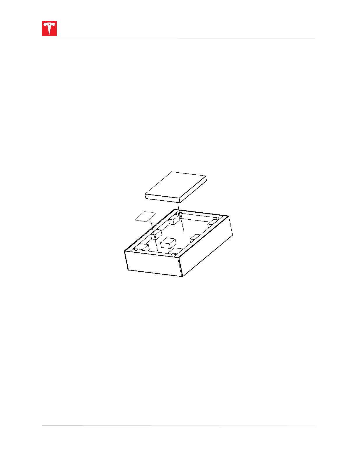
2. Open the box by cutting the packing straps, removing the lid, and setting it aside.
3. Remove the box containing the mounting bracket and the bag containing the accessories.
.
Figure 4: Removing the Mounting Bracket Box and Accessory Bag
4. Verify that the contents of the bracket box and accessory bag are complete and
undamaged (see “Powerwall Box Contents,” above).
5. Remove the top panel and set it aside.
12 Powerwall Installation Manual
Page 15
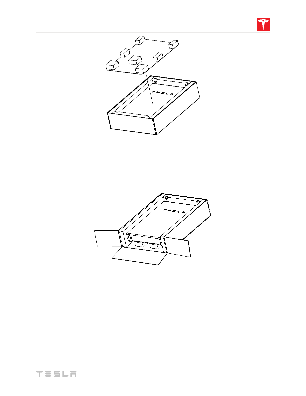
Figure 5: Removing the Top Panel
6. Find the bottom of Powerwall by identifying the feet at the base of the unit.
7. Remove the piece of foam next to the bottom of Powerwall.
8. Open the bottom edge of the box (nearest the bottom of Powerwall) by removing the
staples and folding the cardboard back.
Figure 6: Opening the Bottom of the Powerwall Box
9. Optional: Remove the foam blocks from the top panel and use the cardboard as protective
padding on the lift equipment.
10. Move the lift equipment into place next to the bottom of the Powerwall box.
11. Grasp the top of the Powerwall and carefully tilt it upright until it sits vertically in the box,
with the front of the unit facing the lift equipment.
13
Page 16

Figure 7: Removing Powerwall from Its Box
12. Position the Powerwall on the lift equipment, with the mounting cleats facing away from
the lift equipment.
13. Strap the Powerwall to the lift equipment with a ratcheting tie-down strap.
Step 3. Anchor the Powerwall Mounting Bracket
1. Before mounting the wall bracket, double-check that the mounting location will allow access
to the chosen cable entry port (side or back) during installation. If applicable, use a stud
sensor to locate and mark the centers of the studs in the wall.
2. Determine the appropriate type and number of fasteners for the mounting bracket location.
Be sure to take into account the thickness of the mounting bracket, washers, and wall material
when choosing fasteners. The following guidelines apply to both wall- and floor-mount
installations.
NOTE: The details below are minimum guidelines and are not guaranteed to be applicable.
Refer to local building codes to ensure the use of appropriate fasteners. Refer to
Anchorage Details
for complete mounting information.
Powerwall 2
14 Powerwall Installation Manual
Page 17

Wood Studs (spaced at 12, 16, 20 or 24 inches)
• If anchoring directly into wood studs, use at least
four (one in each corner) 1/4-inch
wood screws with washers, of sufficient length for at least 1.5 in (38 mm) embedment
into the studs.
Figure 8: Anchoring the Bracket to Wood Studs
• If anchoring to blocking between wood studs, use minimum 2 x 4 in blocks, end-nailed
into studs with two 16d (90 mm) nails or toe-nailed into studs with four 8d (60 mm)
nails. Use at least
four (one in each corner) 1/4-inch wood screws with washers, of
sufficient length for at least 1.5 in (38 mm) embedment into the blocking.
Figure 9: Anchoring the Bracket to Blocking between Wood Studs
15
Page 18

Plywood
• If anchoring to plywood wall material, the plywood must be minimum 1/2-inch thick.
Use at least
four (one in each corner) 1/4-inch wood screws with washers, of sufficient
length to penetrate at least 1/4 inch beyond the backside of the plywood.
Figure 10: Anchoring the Bracket to Plywood
Metal Studs (spaced at 12, 16, 20 or 24 inches)
• If anchoring directly to metal studs, studs must be minimum 18 gauge. Use at least
(one in each corner) #14 sheet metal screws with washers, of sufficient length to
penetrate at least 3 threads beyond the stud.
Figure 11: Anchoring the Bracket to Metal Studs
four
16 Powerwall Installation Manual
Page 19

• If anchoring to backing between metal studs, studs must be minimum 25 gauge, and
backing must be minimum 22 gauge. Use at least
eight (two in each corner) #14 sheet
metal screws with washers, of sufficient length to penetrate at least 3 threads beyond
the backing.
Figure 12: Anchoring the Bracket to Metal Backing
• If anchoring to backing between metal studs in an outdoor high wind area, studs must
be minimum 25 gauge, and backing must be minimum 22 gauge. Use at least
twelve
(three in each corner) #14 sheet metal screws with washers, of sufficient length to
penetrate at least 3 threads beyond the backing.
Figure 13: Anchoring the Bracket to Metal Backing – High Wind Area
17
Page 20

Concrete or Masonry
• Minimum strength must be 2500 PSI (concrete) or 1500 PSI (masonry).
• Use at least
four (one in each corner) 1/4-inch fasteners with washers, of sufficient
length for at least 1.5 in (38 mm) embedment into the material. Ensure that all fasteners
are at least 1.5 in (38 mm) away from the edges of masonry blocks or bricks.
Figure 14: Anchoring the Bracket to Concrete or Masonry
Channel Strut (Unistrut)
• Struts must be minimum 1-5/8 in x 1-5/8 in, 12 gauge.
• If mounting on wood studs, attach the strut to at least three studs, using at least one
1/4-inch wood screw with washer per stud, of sufficient length for at least 1.5 in (38
mm) embedment into the studs.
• If mounting on metal studs, attach the strut to at least three studs, using at least two
#14 sheet metal screws with washers per stud, of sufficient length to penetrate at least
3 threads beyond the studs.
• To attach the bracket to the struts, use at least
four (one in each corner) 1/4-inch
hexhead screws with washers and strut nuts.
Figure 15: Anchoring the Bracket to Channel Strut
18 Powerwall Installation Manual
Page 21

NOTE: Both floor and wall mount installations require the cleats on the back of Powerwall to
be fully engaged in the mounting bracket. Consider the floor contour when measuring for
floor-mounted installations.
3. Use the bracket as a guide to mark the location of pilot holes for the required fasteners. Use
a level tool to ensure that the bracket is level.
4. Drill the pilot holes for the fasteners.
5. Attach the bracket to the mounting surface with the required fasteners as described above.
6. Verify that the bracket is firmly attached to the wall.
7. (Back cable entry installation only) Drill a hole in the wall that corresponds to the location of
the back cable entry port on Powerwall. The diameter of the port and location of its center in
are shown below in relation to the Powerwall chassis (Fig 16) and in relation to the installed
mounting bracket (Fig 17).
Figure 16: Back Cable Entry Port Location (Viewed from Front of Powerwall)
19
Page 22

Figure 17: Back Cable Entry Port Location –DETAIL (Viewed from Front of Powerwall)
8. (Optional) Use painter’s tape to mark the location of the bracket flanges on the wall, the
location of the cleats on the front of the Powerwall, and the center lines of the bracket and
chassis to aid in aligning the unit.
20 Powerwall Installation Manual
Page 23

Step 4. Prepare Powerwall for Mounting
1. Switch off Powerwall by moving the switch on the right side of the unit to the OFF position.
WARNING: Switching off Powerwall disengages the Enable line but does not disconnect
AC voltage. High voltage may be present on the AC connection leads unless the Backup
Gateway, any associated circuit breakers, and the AC disconnect (if applicable) are switched
off.
Figure 18: Switching Powerwall Off
2. Remove the left side cover from Powerwall by carefully pulling out on the plastic straps near
the top and bottom of the cover, and detaching it from the clips along the length of the unit.
Figure 19: Removing the Left Side Cover
21
Page 24

3. (Side cable entry installations only) Remove the side cable entry door from the left side
cover by sliding it out of its slot.
Figure 20: Removing the Side Cable Entry Door
Back cable entry installations only) Remove the plug from the back cable entry port on
4. (
Powerwall and place it in the side cable entry port.
Figure 21: Moving the Back Cable Entry Plug to the Side Cable Entry Port
5. Record the serial number of the Powerwall in the back of the Owner’s Manual that came
with the Backup Gateway. The serial number can be found on a label on the left side of the
unit, and also on the lid of its packaging.
22 Powerwall Installation Manual
Page 25

Step 5. Mount Powerwall on the Bracket
1. Move the lift equipment close to the wall and remove the tie-down strap securing the
Powerwall to the lift equipment.
2. Adjust the height of the Powerwall so that its mounting cleats are just above the flanges on
the bracket. (If you marked the bracket and cleat locations, use those marks to gauge the
height.)
3. Begin to lower the Powerwall so that the top cleat engages the top flange on the bracket.
Ensure that the bottom cleat aligns with the bottom flange of the bracket.
4. With both cleats engaged, lower the Powerwall onto the bracket. When the cleats are
seated in the bracket, the locking mechanism at the center of the top flange should click into
place.
NOTE: To remove Powerwall from the mounting bracket, place a thin piece of sheet metal
between the Powerwall unit and the bracket to compress the locking mechanism, and lift the
Powerwall straight up.
Figure 22: Mounting Powerwall on the Bracket
23
Page 26

5. Make sure the unit is centered on the bracket. (If you marked the center lines of the chassis
and bracket, use those marks to align the centers.)
6. (Floor mount installations only) Use the provided shims to ensure that Powerwall is level.
The unit should be level within +/– 2 degrees side-to-side and within +/– 5 degrees front-toback.
Figure 23: Leveling Powerwall with a Shim
24 Powerwall Installation Manual
Page 27

Step 6. Prepare the Backup Gateway for Mounting
1. Remove the Backup Gateway from its packaging and verify that the contents are complete
and undamaged (see “Backup Gateway Box Contents,” above).
2. Record the serial number of the Backup Gateway in the back of the Owner’s Manual that
came with the system. The serial number can be found on a label on the inside of the
enclosure door, and also on the outside of its packaging.
3. Open the Backup Gateway enclosure and remove the enclosure door.
4. Remove the screw at the bottom of the dead front panel and remove it from the enclosure.
Figure 24: Removing the Dead Front Panel from the Enclosure
5. Determine whether cable entry to the Backup Gateway will be from the top, bottom, or side
of the enclosure. If cable entry will be from the top, skip to Step 7, “Install a Circuit Breaker in
the Backup Gateway.”
6. To configure the Backup Gateway for cable entry from the bottom or sides, do the
following:
• Remove the four fasteners holding the back panel assembly in place and remove it
from the enclosure.
• Rotate the back panel assembly 180 degrees and reinstall it in the enclosure.
25
Page 28

Figure 25: Rotating the Back Panel Assembly in the Enclosure
7. Determine if a circuit breaker is required for the installation:
• If no circuit breaker is required, remove and rotate the dead front panel insert (and its
insulation) 180 degrees, and reattach it to compensate for the inverted back panel.
Figure 26: Rotating the Dead Front Panel Insert
• If a circuit breaker is required, proceed to the next step, “Install a Circuit Breaker in the
Backup Gateway.”
26 Powerwall Installation Manual
Page 29

Step 7. Install a Circuit Breaker in the Backup Gateway
Siemens MBK 100A
100 A
EQ8681
Siemens MBK 125A
125 A
EQ8682
Siemens MBK 150A
150 A
EQ8693
Siemens MBK 200A
200 A
EQ8695
If the Backup Gateway is to be located between the electrical service entry and the main
electrical panel, a circuit breaker must be added to the service inlet of the Backup Gateway. If
no circuit breaker is required, skip to Step 8, “Mount the Backup Gateway.”
WARNING: If a circuit breaker is not added to the Backup Gateway, ensure that
appropriate overcurrent protection is provided for the installation.
CAUTION: To reduce the risk of fire, connect only to a circuit provided with 200 A
maximum branch-circuit overcurrent protection, in accordance with the National Electrical
Code, ANSI/NFPA 70.
The following circuit breaker models are supported:
Circuit Breaker Model Amperage Rating UL Type
1. Determine the level of overcurrent protection required, based on local code requirements.
2. Remove the service inlet terminal lugs from the Backup Gateway. (It may be necessary to
remove the meter current transformers to access the nuts holding the lugs in place.)
Figure 27: Removing the Inlet Service Terminal Lugs
3. Install the corresponding size circuit breaker at the service inlet terminals in the Backup
Gateway.
27
Page 30

4. Remove and rotate the dead front panel insert (and its insulation) so that the correct
punch-out will match the breaker location when the panel is replaced. For smaller (100 A and
125 A) circuit breakers, remove the small punch-out; for larger (150 A and 200 A) circuit
breakers, remove the large punch-out.
NOTE: The location of the breaker also depends on the orientation of the back panel
assembly.
Figure 28: Dead Front Panel Insert Orientations for Circuit Breakers
Step 8. Mount the Backup Gateway
1. Determine the mounting location. The Backup Gateway enclosure has 3 mounting holes
(shown below in red). If needed, two additional mounting points (shown below in grey) are
also available. To use these additional mounting points, the back panel must be removed and
the points drilled out.
Figure 29: Backup Gateway Mounting Hole Locations (Back View)
28 Powerwall Installation Manual
Page 31

2. Drill pilot holes in the mounting surface for the fasteners.
3. Attach the Backup Gateway enclosure to the mounting surface. Use a level tool to ensure
that the enclosure is level.
Figure 30: Mounting the Backup Gateway
29
Page 32

1
Communication OUT Connector (for daisy-chaining multiple Powerwalls)
2
Communication IN Connector (for single Powerwall or first Powerwall in a chain)
3
AC Connector
4
Ground Lug
Step 9. Connect Powerwall and the Backup Gateway
NOTE: When wiring Powerwall and the Backup Gateway, Class 1 wiring methods are to be
used for wiring connections to terminals of Class 2 circuits.
1. Using the provided Torx T20 bit, remove the cover from the wiring compartment on the left
side of Powerwall.
Figure 31: Removing the Wiring Compartment Cover
Depending on regional requirements, Powerwall wiring can be installed through conduit or
through a cable gland. Refer to local codes to determine wiring requirements.
Figure 32: Powerwall 2 AC Wiring Compartment Inlet and Connectors
30 Powerwall Installation Manual
Page 33

2. (Conduit installations only) Run conduit as needed and attach the conduit fitting to the inlet
of the wiring compartment. The wiring compartment inlet accepts a standard 1-inch conduit
fitting.
Figure 33: Powerwall 2 AC Side Cable Port Entry location
3. (Conduit installations only) If the conduit connector does not have an integrated bushing,
affix the provided insulation bushing to the conduit opening on the inside of the wiring
compartment.
NOTE: Ensure that all conduit joints and outlets have smooth edges so that wiring is not
damaged as it is run through the conduit.
31
Page 34

Communication Connector Wiring
Terminal
Connector Terminal Name
Recommended Wire Color
Wire Gauge
1
12V + (Logic +)
Brown
0.2–1.5 mm2 (24–16 AWG)
2
GND (Logic –)
White
0.2–1.5 mm2 (24–16 AWG)
3
CAN HI
Blue
0.2–1.5 mm2 (24–16 AWG)
4
CAN LO
Yellow
0.2–1.5 mm2 (24–16 AWG)
4. Run the 4-conductor communication cable, the high-voltage AC conductors and highvoltage grounding conductor through the conduit or cable gland and pull them into the
Powerwall wiring compartment.
5. Run the other end of the 4-conductor communication cable, the high-voltage AC
conductors and high-voltage grounding conductor into the Backup Gateway enclosure.
6. On the Backup Gateway side, strip the end of the high-voltage grounding conductor and
insert it in the ground bar in the Backup Gateway enclosure (Fig 35). The ground bar is
identified with the following symbol: . Tighten the screw in the ground bar to 5.5 Nm (50 lbin).
7. On the Powerwall side, strip the end of the high-voltage grounding conductor and insert it in
the Powerwall chassis ground lug (Fig 36). The ground lug is identified with the following
symbol: . Tighten the screw in the ground lug to 4.5 Nm (40 lb-in).
8. On each end of the 4-conductor communication cable, strip and insert the wires into the
provided 4-pin Phoenix connectors according to the following table and diagram (Fig. 34). On
the Powerwall side, use the black Phoenix connector.
Figure 34: Communication Connector Wiring
9. On the backup Gateway side, plug the 4-pin Phoenix connector into the 4-pin connector at
the bottom left of the enclosure.
32 Powerwall Installation Manual
Page 35

Figure 35: Backup Gateway Ground and Communication Connections
10. On the Powerwall side, plug the 4-pin Phoenix connector into the bottom 4-pin connector
(labeled “IN”) in the Powerwall wiring compartment.
Figure 36: Powerwall 2 AC Ground and Communication Connections
NOTE:
should be terminated at the Backup Gateway only.
Do not connect the cable shield to the Powerwall chassis ground lug
. The shield
33
Page 36

Backup Gateway AC Wiring
Service Connection
Backup Gateway Terminal
Wire Gauge
Line 1
S1
16–120 mm2 (6 AWG - 250 kcmil)
Line 2
S2
16–120 mm2 (6 AWG - 250 kcmil)
Neutral
N
16–120 mm2 (6 AWG - 250 kcmil)
Step 10: Make AC Power Connections
1. Determine whether the installation requires that neutral be bonded to ground in the Backup
Gateway. (In most cases, if the Backup Gateway is to be located between the electrical service
entry and the main electrical panel, neutral should be bonded to ground, otherwise, bonding
should be removed.)
The Backup Gateway ships with neutral bonded to ground. To remove bonding, disconnect
the green wire between the ground bar and the neutral terminals.
Figure 37: Backup Gateway Ground Bar (top left) Bonded to Neutral (bottom right)
2. Connect the electrical service from the service inlet or from the main panel (depending on
the backup configuration) to the Backup Gateway terminals according to the following table
and diagram (Fig 38). Strip the ends of the wires and insert them in the corresponding Backup
Gateway terminal lugs. Tighten the lugs to 30 Nm (22 lb-ft).
NOTE: For electrical service connections to the Backup Gateway, use 16-120 mm2 (6 AWG to
250 kcmil), 90 deg C minimum copper (Cu) wire.
34 Powerwall Installation Manual
Page 37

Figure 38: Backup Gateway Power Connector Labels (shown with breaker installed)
3. Connect Powerwall to the main or sub electrical panel of the installation (depending on the
backup configuration) according to the following tables, for your electrical service type.
NOTE: For AC power connections to Powerwall, use 5–8 mm2 (10-8 AWG) 90 deg C minimum
copper (Cu) wire.
35
Page 38

Main/Sub Panel Breaker Terminal
Powerwall Terminal
Wire Gauge
Line 1
L1
5–8 mm2 (10-8 AWG)
Neutral
L2
5–8 mm2 (10-8 AWG)
Main/Sub Panel Breaker Terminal
Powerwall Terminal
Wire Gauge
Line 1
L1
5–8 mm2 (10-8 AWG)
Neutral
N
5–8 mm2 (10-8 AWG)
Line 2
L2
5–8 mm2 (10-8 AWG)
Main/Sub Panel Breaker Terminal
Powerwall Terminal
Wire Gauge
Line 1
L1
5–8 mm2 (10-8 AWG)
Line 2
L2
5–8 mm2 (10-8 AWG)
100 V, 120 V, 200 V, 220 V, 230 V, 240 V Single-Phase Service
NOTE: For single-phase service, Neutral is not connected to the Powerwall N terminal. It is
instead connected to the Powerwall L2 terminal.
120/240 V Split-Phase Service
208 V Service
4. On the Powerwall side, strip the ends of the wires and attach them to the corresponding
leads on the 3-pin AC power harness using the provided wirenuts.
5. Plug the AC power harness into the AC connector in the Powerwall wiring compartment.
Ensure that the connector clicks into place.
NOTE: The Powerwall connection to the main electrical panel requires a 30 A circuit breaker
with a maximum short circuit current rating of 10 kA. This breaker serves as the disconnect for
the Powerwall, and must be wired in accordance with local wiring codes and regulations.
36 Powerwall Installation Manual
Figure 39: Powerwall 2 AC Power Harness Connection
Page 39

Step 11. Close the Wiring Compartments and Turn On the System
1. Arrange the communication and AC power wires inside the Powerwall wiring compartment.
2. Ensure that all conduit or cable gland junctions and cable entry points are secure and
properly sealed.
3. Replace the cover on the wiring compartment. Ensure that the cover seats properly on the
gasket so that the compartment is sealed. Tighten the fasteners using the provided Torx T20
bit. Torque to 1.5 Nm (13 lb-in).
4. Replace the left side cover on Powerwall by pushing the top into place and working toward
the bottom to reattach it to the clips along the length of the unit.
5. Replace the dead front panel in the Backup Gateway and remount its door.
6. Switch on the circuit breaker to the Backup Gateway.
7. Switch on Powerwall by moving the switch on the right side of the unit to the ON position.
When Powerwall establishes communication with the Backup Gateway, the LED on the right
side of Powerwall illuminates.
Figure 40: Switching Powerwall On
Step 12. Commission the Backup Gateway and Verify System Operation
After all components of the system have been turned on, do the following to begin the Backup
Gateway commissioning process:
1. Using any web-capable wireless device, establish communication with the Backup Gateway
over the local wireless network.
2. Connect to the Backup Gateway web interface: the username is your email address, and the
password is the Backup Gateway serial number.
3. Follow the on-screen steps to commission the system.
4. Apply any firmware updates to the Backup Gateway and Powerwall as required.
5. Verify that Powerwall is receiving commands from the Backup Gateway and is capable of
charging and discharging correctly in response to the corresponding commands.
37
Page 40

LED State
Indication
On (solid)
Powerwall enabled/Communication with Backup Gateway;
High voltage may be present on Powerwall AC connectors
On (flashing)
Powerwall enabled/No communication with Backup Gateway;
High voltage may be present on Powerwall AC connectors
On (pulsing)
Powerwall enabled and charging or discharging
Rate of pulsing proportional to power flow
Off
Powerwall not enabled or switched off
Step 13. Finish Installation and Register the System
1. After installation is complete, remove the protective film from Powerwall.
2. Remove the plastic straps from the left and right side covers by cutting them and carefully
pulling them through the slots in the covers.
3. If you have not already done so, register the system by visiting
www.tesla.com/support/powerwall.
4. Leave the Powerwall Owner’s Manual with the owner of the newly installed system.
Troubleshooting
If Powerwall is not working correctly, perform the following steps:
• Check the status of the LED on the right side of Powerwall.
The LED indicates status as follows:
• If it is not possible to communicate with the Backup Gateway through the My Tesla
app, ensure that the home Internet connection is working.
• Ensure that Powerwall is correctly connected to the Backup Gateway, based on the
wiring diagrams above and site design information.
WARNING: Before opening the Powerwall wiring compartment, make sure to
switch off the AC breakers for Powerwall and the Backup Gateway, switch off the AC
disconnect (if applicable), and switch off Powerwall.
WARNING: Switching off Powerwall disengages the Enable line but does not
disconnect AC voltage. High voltage may be present on the AC connection leads
unless the Backup Gateway, any associated circuit breakers, and the AC disconnect (if
applicable) are switched off.
• If a brownout or blackout is experienced during backup operation: reduce the loads
and check that the breakers have not opened.
• If Powerwall does not operate and the ambient temperature is high, increase ventilation
if needed.
38 Powerwall Installation Manual
Page 41

• If the Backup Gateway and Powerwall are both unresponsive:
1. Turn off Powerwall by setting its On/Off switch to the OFF position.
2. Turn off the AC breakers for the system (Backup Gateway and Powerwall).
3. Wait at least one minute.
4. Turn the AC breakers back on.
5. Turn on Powerwall.
Technical Support
Resources for Certified Installers, including service request forms and the latest versions of
installation manuals, are available at https://www.tesla.com/support/powerwall.
If further support is needed, contact the Tesla Service team at the support phone number for
your region. Support numbers for all regions are found at:
https://www.tesla.com/support/powerwall
This information is useful to have ready when contacting Tesla:
• Owner name
• Best point of contact for Tesla to return contact (name, phone number, email)
• Powerwall part number and serial number
• Brief description of the issue
Maintenance
Powerwall does not require pre-scheduled preventative maintenance. The only maintenance
required by an owner is to keep the unit free and clear of debris, especially around the air
intake and exhaust.
To clean Powerwall, use a soft, lint-free cloth. If needed, the cloth can be dampened with mild
soap and water only. Do not use cleaning solvents to clean Powerwall, or expose Powerwall to
flammable or harsh chemicals or vapors.
39
Page 42

Powerwall Wiring
Powerwall Terminal
Wire Color
Wire Gauge
1
12V + (Logic +)
Brown
0.2–1.5 mm2 (24–16 AWG)
2
GND
White
0.2–1.5 mm2 (24–16 AWG)
3
CN + (CAN HI)
Blue
0.2–1.5 mm2 (24–16 AWG)
4
CN – (CAN LO)
Yellow
0.2–1.5 mm2 (24–16 AWG)
5
L2 (Line 2)
Red
5–8 mm2 (10–8 AWG)
6
N (Neutral)
White
5–8 mm2 (10–8 AWG)
7
L1 (Line 1)
Black
5–8 mm2 (10–8 AWG)
8
Chassis Ground Lug
Green or Green/Yellow
5–8 mm2 (10–8 AWG)
Powerwall
Wiring Reference
40 Powerwall Installation Manual
Page 43

Backup Gateway
Backup Gateway Wiring
Backup Gateway Terminal
Wire Color
Wire Gauge
1
12V + (Logic +)
Brown
0.2–1.5 mm2 (24–16 AWG)
2
GND
White
0.2–1.5 mm2 (24–16 AWG)
3
CN + (CAN HI)
Blue
0.2–1.5 mm2 (24–16 AWG)
4
CN – (CAN LO)
Yellow
0.2–1.5 mm2 (24–16 AWG)
5
Ethernet
CAT5
6
Ground Bar
Green or Green/Yellow
2.5–70 mm2 (14 AWG–2/0)
7
Line 1 Source (S1)
Black
16–120 mm2 (6 AWG–250 kcmil)
8
Line 2 Source (S2)
Red
16–120 mm2 (6 AWG–250 kcmil)
9
Neutral (N)
White
16–120 mm2 (6 AWG–250 kcmil)
10
Line 1 Load x 2 (L1)
Black
16–120 mm2 (6 AWG–250 kcmil)
11
Line 2 Load x 2 (L2)
Red
16–120 mm2 (6 AWG–250 kcmil)
12
Neutral x 2 (N)
White
16–120 mm2 (6 AWG–250 kcmil)
41
Page 44

Voltage
Range*
Time
(sec)
Voltage
Range*
Time
(sec)
V ≥ 120
0.16
Powerwall Inverter Adjustable Settings
The Powerwall inverter has the following adjustable settings, which are determined when the
system is commissioned.
NOTE: Under abnormal voltage or frequency conditions or in response to a detected
unintentional island, the system will disconnect from the grid by opening its internal contactor.
NOTE: All values are for factory default 240 V @ 60 Hz.
Voltage Ride-Through
The Powerwall inverter has three voltage and time set points for low voltage ride-through,
configurable to the following ranges (measured as line to neutral for single-phase, and line-toline for split-phase):
Inverter LVRT Settings
Parameter
LVRT Point 3 0-400 V 108 V 0-60 100 ms or 1%, whichever is greater
LVRT Point 2 0-400 V 144 V 0-60 100 ms or 1%, whichever is greater
LVRT Point 1 0-400 V 192 V 0-60 100 ms or 1%, whichever is greater
LVRT Point 0 0-400 V 216 V 0-60 100 ms or 1%, whichever is greater
*Voltage accuracy 2% of nominal
Default Value*
Accuracy
The inverter has three voltage and time set points for high voltage ride-through, configurable
to the following ranges (measured as line to neutral for single-phase, and line to line for splitphase):
Inverter HVRT Settings
Parameter
HVRT Point 3 0-400 V 336 V 0-60 100 ms or 1%, whichever is greater
HVRT Point 2 0-400 V 288 V 0-60 100 ms or 1%, whichever is greater
HVRT Point 1 0-400 V 264 V 0-60 100 ms or 1%, whichever is greater
HVRT Point 0 0-400 V 254.4 V 0-60 100 ms or 1%, whichever is greater
*Voltage accuracy 2% of nominal
Default Value*
Accuracy
The above tables represent the maximum parameter values that the user can input. However,
240 VAC nominal systems are limited to a maximum HVRT of 120%.
The inverter ships with the pre-defined settings listed below.
Interconnection System Default Response to Abnormal Voltages
Voltage Range (% of base voltage) Clearing Time (s)
V < 45 0.16
45 ≤ V < 60 1
60 ≤ V < 88 2
110 < V < 120 1
42 Powerwall Installation Manual
Page 45

In addition to ride-through capability, the inverter is capable of adding or removing VARs
Default
Time
(sec)
UF2
< 59.5
2
OF1
> 60.5
2
OF2
> 62
0.16
during VRT events to help support voltage regulation during the fault event.
During a grid fault, the inverter maintains its output power set point unless it is operating in
current limit or the reactive current demand consumes the available output current capacity.
Frequency Ride-Through
The inverter has three under-frequency (UF) and three over-frequency (OF) trip points and
times. These parameters are configurable to the ranges listed below.
Inverter Frequency Trip Points
Trip Point Frequency Range*
UF Trip Point 3 35 Hz-70 Hz 3:55 0-600 100 ms or 1%, whichever is greater
UF Trip Point 2 35 Hz-70 Hz 2:57 0-600 100 ms or 1%, whichever is greater
UF Trip Point 1 35 Hz-70 Hz 1:59.5 0-600 100 ms or 1%, whichever is greater
UF Trip Point 0 35 Hz-70 Hz 0:59.5 0-600 100 ms or 1%, whichever is greater
OF Trip Point 0 35 Hz-70 Hz 0:60.5 0-600 100 ms or 1%, whichever is greater
OF Trip Point 1 35 Hz-70 Hz 1:60.5 0-600 100 ms or 1%, whichever is greater
OF Trip Point 2 35 Hz-70 Hz 2:62 0-600 100 ms or 1%, whichever is greater
OF Trip Point 3 35 Hz-70 Hz 3:65 0-600 100 ms or 1%, whichever is greater
*Frequency accuracy 0.2 Hz of nominal
Value
Accuracy
The FQRT settings are pre-programmed in the inverter to comply with IEEE 1547
requirements.
Inverter FQRT Default Settings
Function Frequency (Hz) Clearing Time (s)
UF1 < 57 0.16
43
Page 46

Powerwall Inverter Short Circuit Information
Grid-Tied Mode Inverter Short Circuit Information
Short Initial Peak Breaking
Max Current
(Amps RMS)
Duration
(ms)
Max Current
(Amps)
Duration
(ms)
Max Current
(Amps RMS)
Duration
(ms)
L1 – L2 110 16.7 248 8.9 58.2 16.7
L1 - GND 20.5 16.7 268 8.6 9.24 16.7
L2 - GND 22 16.7 264 7.2 6.82 16.7
Stand-Alone Inverter Short Circuit Information
Short
Max Current, Amps
(3 cycle RMS)
L1 – L2 51.3 248 8.9
L1 - Neutral 50.5 268 8.6
L2 - Neutral 45.6 264 7.2
Max Current, Amps
(Peak to Peak)
Peak Duration
(ms)
44 Powerwall Installation Manual
Page 47

Page 48

Tesla, Inc.
Palo Alto, CA 94304
Tesla Motors Netherlands B.V.
Tilburg, Netherlands
3500 Deer Creek Road
Rev 1.0 Mar 21, 2017
Atlasstraat 7–9, 5047 RG
 Loading...