

Page 1

POWERWALL INSTALLATION MANUAL
FOR POWERWALL 1067000-00-C WITH SMA AND SOLAREDGE INVERTERS
Page 2
For the latest Powerwall installation documents in all
supported languages, go to:
www.teslamotors.com/support/powerwall-installer
To secure the full 10-year product warranty for the owner, be
sure to register Powerwall online.
Warning: Read this entire document before installing or
using Powerwall. Failure to do so or to follow any of the
instructions or warnings in this document can result in
electrical shock, serious injury, or death, or can damage
Powerwall, potentially rendering it inoperable.
PRODUCT SPECIFICATIONS
All specifications and descriptions contained in this document are verified to be accurate at
the time of printing. However, because continuous improvement is a goal at Tesla, we reserve
the right to make product modifications at any time.
The images provided in this document are for demonstration purposes only. Depending on
product version and market region, details may appear slightly different.
ERRORS OR OMISSIONS
To communicate any inaccuracies or omissions in this manual, please send an email to:
energymanualfeedback@teslamotors.com.
ELECTRONIC DEVICE: DO NOT THROW AWAY
Proper disposal of batteries is required. Refer to your local codes for disposal
requirements.
MADE IN THE USA
©2016 TESLA MOTORS, INC. All rights reserved.
All information in this document is subject to copyright and other intellectual property rights of Tesla Motors, Inc.
and its licensors. This material may not be modified, reproduced or copied, in whole or in part, without the prior
written permission of Tesla Motors, Inc. and its licensors. Additional information is available upon request. The
following are trademarks or registered trademarks of Tesla Motors, Inc. in the United States and other countries:
TESLA TESLA MOTORS POWERWALL
All other trademarks contained in this document are the property of their respective owners and their use herein
does not imply sponsorship or endorsement of their products or services. The unauthorized use of any trademark
displayed in this document or on the product is strictly prohibited.
Page 3

Contents
Important Safety Instructions............................................................................. 2
SYMBOLS IN THIS DOCUMENT..................................................................................................................................... 2
GENERAL INFORMATION................................................................................................................................................ 2
ENVIRONMENTAL CONDITIONS...................................................................................................................................3
Specifications............................................................................................................ 4
ELECTRICAL SPECIFICATIONS.....................................................................................................................................4
ENVIRONMENTAL SPECIFICATIONS.......................................................................................................................... 4
MECHANICAL SPECIFICATIONS...................................................................................................................................4
Site Requirements....................................................................................................5
PHYSICAL REQUIREMENTS............................................................................................................................................5
TEMPERATURE REQUIREMENTS..................................................................................................................................5
INSTALLATION REQUIREMENTS.................................................................................................................................. 5
MINIMUM SPACE REQUIREMENTS...............................................................................................................................6
Step-by-Step Installation Instructions............................................................. 7
REQUIRED TOOLS.............................................................................................................................................................. 7
STEP 1 - REMOVE THE LID AND BOTTOM COVER................................................................................................ 8
STEP 2 - REMOVE THE SPLASH COVER....................................................................................................................9
STEP 3 - SET THE COMMUNICATION SWITCHES................................................................................................10
STEP 4 - SET THE ADDRESS SWITCHES...................................................................................................................11
STEP 5 - PREPARE THE WIRING..................................................................................................................................12
STEP 6 - CONNECT THE WIRING................................................................................................................................14
STEP 7 - ATTACH THE SPLASH COVER....................................................................................................................16
STEP 8 - REMOVE THE PALLET................................................................................................................................... 17
STEP 9 - DETERMINE THE MOUNTING LOCATION FOR POWERWALL.....................................................19
STEP 10 - INSTALL THE WALL MOUNT BRACKET...............................................................................................19
STEP 11 - MOUNT POWERWALL.................................................................................................................................20
STEP 12 - REMOVE THE PACKAGING.........................................................................................................................21
STEP 13 - FEED WIRES THROUGH THE CONDUIT PLATE OR CABLE GLAND....................................... 22
STEP 14 - CONNECT MULTIPLE POWERWALLS TOGETHER..........................................................................23
STEP 15 - CONNECT POWERWALL TO THE INVERTER................................................................................... 23
STEP 16 - ATTACH THE SIDE COVERS.....................................................................................................................24
STEP 17 - ATTACH THE BOTTOM COVER................................................................................................................25
STEP 18 - REPACK THE SHIPPING BOX....................................................................................................................25
Operation and Care.............................................................................................. 26
NORMAL OPERATION.................................................................................................................................................... 26
POWERWALL CARE........................................................................................................................................................26
TROUBLESHOOTING.......................................................................................................................................................26
What to Do in Case of an Emergency...........................................................27
Page 4
Important Safety Instructions
SAVE THESE IMPORTANT SAFETY INSTRUCTIONS. Powerwall installation and repair instructions
assume knowledge of high voltage electricity and should only be performed by Tesla Energy
Certified Installers. Tesla Motors assumes no liability for injury or property damage due to repairs
attempted by unqualified individuals or a failure to properly follow these instructions. These
warnings and cautions must be followed when using Powerwall.
SYMBOLS IN THIS DOCUMENT
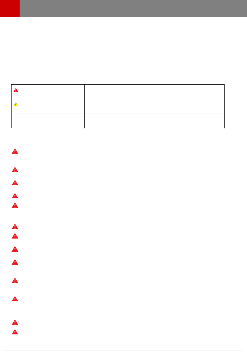
This manual uses the following symbols to highlight important information:
Warning:
Caution:
Note:
GENERAL INFORMATION
Warning: Read this entire document before installing or using Powerwall. Failure to do so or
to follow any of the instructions or warnings in this document can result in electrical shock,
serious injury, or death, or can damage Powerwall, potentially rendering it inoperable.
Warning: A battery can present a risk of electrical shock, fire, or explosion from vented gases.
Observe proper precautions.
Warning: Powerwall installation must be carried out only by Tesla Energy Certified Installers,
who have been trained in dealing with high voltage electricity.
Warning: Powerwall is heavy and challenging to lift.
Warning: Use Powerwall only with a Tesla-approved inverter. For a list of compatible inverters,
go to:
www.teslamotors.com/support/powerwall
Warning: Use Powerwall only as directed.
Warning: Do not use Powerwall if it is defective, appears cracked, broken, or otherwise
damaged, or fails to operate.
Warning: Before beginning the wiring portion of the installation, first power o the inverter
and then open the AC and DC disconnect switches (if applicable for the installation).
Warning: Do not attempt to open, disassemble, repair, tamper with, or modify Powerwall.
Powerwall is not user serviceable. Batteries in Powerwall are not replaceable. Contact the
Tesla Energy Authorized Reseller who sold the Powerwall for any repairs.
Warning: Do not connect Powerwall to alternating current carrying conductors. Powerwall
must be wired to either an inverter or a DC combiner panel that is then wired to an inverter.
No other wiring configuration may be used.
Warning: To protect Powerwall and its components from damage when transporting, handle
with care. Do not impact, pull, drag, or step on Powerwall. Do not subject Powerwall to any
strong force. To help prevent damage, leave Powerwall in its shipping packaging until it is
ready to be installed.
Warning: Do not insert foreign objects into any part of Powerwall.
Warning: Do not expose Powerwall or its components to direct flame.
WARNING indicates a hazardous situation which, if not
avoided, could result in injury or death.
CAUTION indicates a hazardous situation which, if not
avoided, could result in damage to the equipment.
NOTE indicates an important step or tip that leads to best
results, but is not safety or damage related.
2 Powerwall Installation Manual
Page 5
Important Safety Instructions
Warning: Do not install Powerwall near heating equipment.
Warning: Do not immerse Powerwall or its components in water or other fluids.
Caution: Do not use cleaning solvents to clean Powerwall, or expose Powerwall to flammable
or harsh chemicals or vapors.
Caution: Do not use fluids, parts, or accessories other than those specified in this manual,
including use of non-genuine Tesla parts or accessories, or parts or accessories not purchased
directly from Tesla or a Tesla-certified party.
Caution: Do not place Powerwall in a storage condition for more than one (1) month, or
permit the electrical feed on the Powerwall to be severed for more than one (1) month,
without placing Powerwall into a storage condition in accordance with Tesla’s storage
specifications.
Caution: Do not paint any part of Powerwall, including any internal or external components
such as the exterior shell or casing.
Caution: Do not connect Powerwall directly to photovoltaic (PV) solar wiring.
Caution: When installing Powerwall in a garage or near vehicles, keep it out of the driving
path. If possible, install the Powerwall on a side wall and/or above the height of vehicle
bumpers.
Caution: Powerwall has a pre-installed aesthetic front cover. To prevent damage, keep
Powerwall flat on its back until just before lifting Powerwall onto the wall mount bracket.
ENVIRONMENTAL CONDITIONS
Warning: Install Powerwall at a height that prevents damage from flooding.
Warning: Operating or storing Powerwall in temperatures outside its specified range might
cause damage to Powerwall.
Warning: Do not expose the Powerwall to ambient temperatures above 60°C (140°F) or
below -30°C (-22°F).
Caution: Ensure that no water sources are above or near Powerwall, including downspouts,
sprinklers, or faucets.
Caution: Ensure that snow does not accumulate on top of or around Powerwall.
Tesla Energy 3
Page 6
Specifications
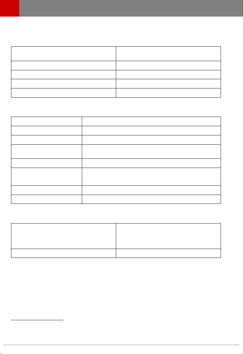
ELECTRICAL SPECIFICATIONS
Charge and Discharge Power, Peak and
Continuous
1
Energy
DC Voltage 350 V to 450 V
DC Current, Maximum and Continuous 9.5 A
Round Trip DC Eciency (Beginning of Life)
1
3.3 kW
6.4 kWh
92.5%
ENVIRONMENTAL SPECIFICATIONS
Operating Temperature
Humidity <95% non-condensing
Storage <=12 months State of Energy (SoE): 25% initial
Noise (at Full Thermal System
Performance)
Maximum Altitude 3000 m (9843 ft)
Ingress Rating IP35 and NEMA 3R (Powerwall)
Impact Rating IK09
Seismic Rating AC156 and IEEE 693-2005
2
<49 dBA front, and <55 dBA top, at a distance of 1m
-20 °C to 50 °C (-4 °F to 122 °F)
IP67 (battery Pod only)
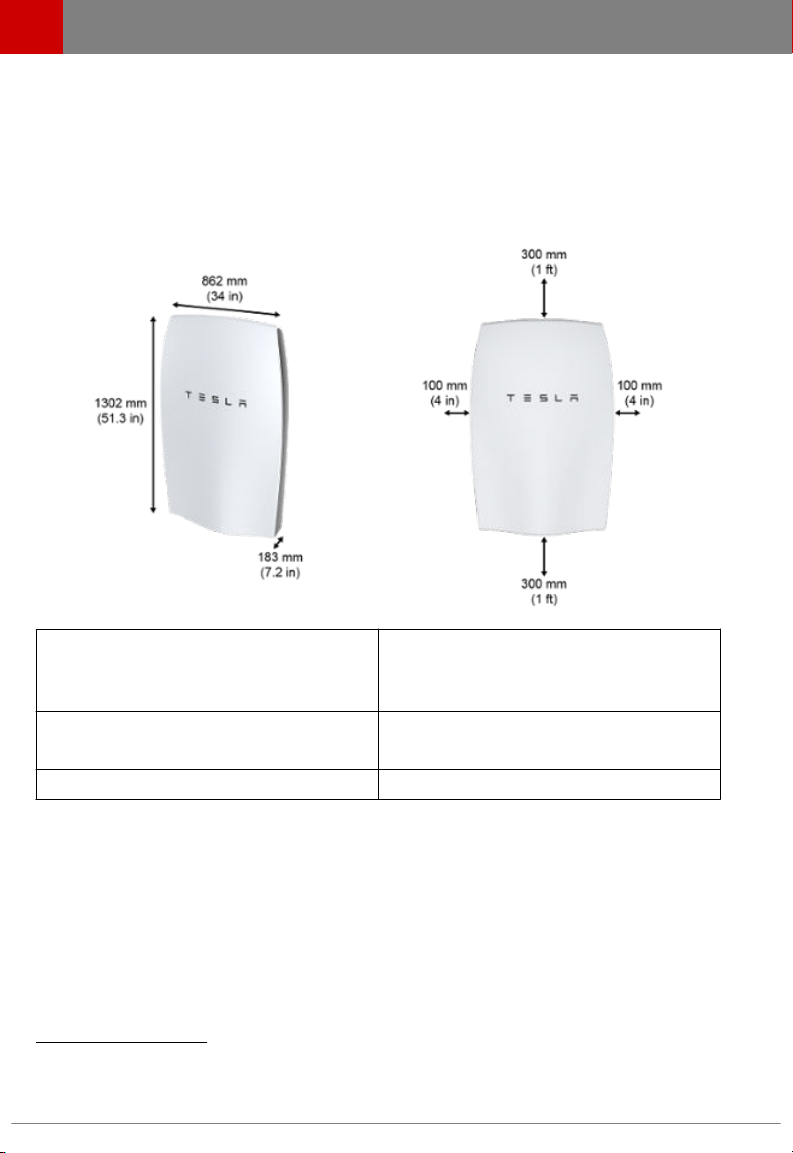
MECHANICAL SPECIFICATIONS
Length
Width
Depth
Weight 97 kg (214 lbs)
1302 mm (51.3 in)
862 mm (34 in)
183 mm (7.2 in)
1
Values provided for 25 °C, 2 kW charge/discharge power, 400 V to 450 V DC bus.
2
Performance might be de-rated in extreme ambient temperatures.
4 Powerwall Installation Manual
Page 7
Site Requirements
PHYSICAL REQUIREMENTS
Powerwall must be installed on an upright wall that can support 115 kg (254 lbs), the maximum
weight of Powerwall and its installation packaging. The wall must be flush and extend to all edges
of the system, allowing no access to the back of the unit once it is mounted. Do not mount
Powerwall horizontally or upside down. Do not mount Powerwall on a wall that is tilted backward
or forward more than 5 degrees.
Powerwall requires adequate clearance for installation, cabling, and airflow. Do not mount any
other objects within the clearance space illustrated below, except those explicitly required by the
installation (for example, conduit or DC disconnect depending on local installation codes). Do not
install anything between Powerwall and the ceiling.
Note: Powerwall has a pump and fan that produce a gentle hum during operation, comparable to
a typical refrigerator or dishwasher. This intermittent noise is normal and enables Powerwall to
maintain ideal battery temperature. The noise level depends on the ambient temperature and the
power level of operation. Choose the installation location of the Powerwall with due consideration
for the owner's sensitivity to noise level.
TEMPERATURE REQUIREMENTS
Powerwall is capable of charging and discharging within the full ambient temperature range listed
in the
Specifications section. At the high and low ends of the temperature range, Powerwall may
limit charge or discharge power based on battery cell temperature to improve battery lifespan.
Installation in full sun raises the temperature inside the enclosure above ambient temperature. This
temperature rise is not a safety risk, but can impact the performance of the batteries. Installation
in full sun is not recommended to optimize the use of Powerwall.
Do not install Powerwall in a room with sustained elevated temperatures, such as a boiler room.
The average ambient temperature over the system's life should be 30°C (86 °F) or less.
INSTALLATION REQUIREMENTS
Powerwall must be installed with a compatible inverter. Wiring and conduit (where necessary)
must be provided by the installer.
DC disconnect requirements between Powerwall and the inverter are subject to local codes.
Ensure that the installation meets local DC disconnect requirements. Check the inverter
installation manual to understand site connections and overcurrent protection.
Tesla Energy 5
Page 8
Site Requirements
All U.S. and Canada electrical installations must be done in accordance with local codes and the
National Electric Code (NEC) ANSI/NFPA 70 or the Canadian Electrical Code CSA C22.1.
All installations must conform to the laws, regulations, codes, and standards applicable in the
jurisdiction of installation.
MINIMUM SPACE REQUIREMENTS
Total ceiling height
Clearance above
Clearance below
Lateral wall space
Clearance from each side
Depth of workspace
3
Depth requirement is typically determined by working clearances required in the local
installation code.
6 Powerwall Installation Manual
3
2000 mm (6.5 ft )
300 mm (1 ft)
300 mm (1 ft)
1070 mm (42 in)
100 mm (4 in)
762 mm (30 in)
Page 9

Step-by-Step Installation Instructions
Warning: Powerwall must be installed by a Tesla Energy Certified Installer.
STEP 1 - REMOVE THE LID AND BOTTOM COVER
STEP 2 - REMOVE THE SPLASH COVER
STEP 3 - SET THE COMMUNICATION SWITCHES
STEP 4 - SET THE ADDRESS SWITCHES
STEP 5 - PREPARE THE WIRING
STEP 6 - CONNECT THE WIRING
STEP 7 - ATTACH THE SPLASH COVER
STEP 8 - REMOVE THE PALLET
STEP 9 - DETERMINE THE MOUNTING LOCATION FOR POWERWALL
STEP 10 - INSTALL THE WALL MOUNT BRACKET
STEP 11 - MOUNT POWERWALL
STEP 12 - REMOVE THE PACKAGING
STEP 13 - FEED WIRES THROUGH THE CONDUIT PLATE OR CABLE GLAND
STEP 14 - CONNECT MULTIPLE POWERWALLS TOGETHER
STEP 15 - CONNECT POWERWALL TO THE INVERTER
STEP 16 - ATTACH THE SIDE COVERS
STEP 17 - ATTACH THE BOTTOM COVER
STEP 18 - REPACK THE SHIPPING BOX
REQUIRED TOOLS
• Wall mount bracket fasteners
Note: The details below are only guidance and are not guaranteed to be applicable. Consult
local building codes and a structural engineer to ensure the use of appropriate fasteners.
• Minimum of 6 fasteners, stainless steel, diameter 10 mm (3/8 in)
• Fastener head clearance for all positions but two bottom outer holes: 18 mm (11/16 in)
• Fastener head clearance for bottom two holes at 600 mm (24 in) spacing: 8 mm (5/16 in)
• Washers between fastener heads and wall mount bracket are recommended
• Drill and a drill bit suitable for drilling pilot holes in the desired mounting surface
• Socket wrench
• 10 mm socket adapter (for covers and wall mount bracket side tabs)
• 17 mm socket adapter (for wood block bolts)
• Large
• Optional: small flathead screwdriver (for wiring terminal tabs)
• T20 Torx (for splash cover and screws fastening box to wood blocks)
• T30 Torx (for packaging L-bracket and conduit/gland plate)
• Torque wrench
• Stud
• Level tool
• Painter's tape and/or pencil
• Wire stripper and wiring (as described in Step 5)
• Conduit
• Lift tool or adequate personnel trained and capable of lifting 115 kg (254 lb) from ground level
flathead screwdriver (for ground lug)
finder (for wood installations)
fitting or cable gland (as appropriate)
to approximately chest height
Warning: Powerwall is heavy and challenging to lift. Lift equipment is recommended.
To prevent injury, wear work boots (preferably steel-toed), long pants, and gloves.
Tesla Energy 7
Page 10

Step-by-Step Installation Instructions
STEP 1 - REMOVE THE LID AND BOTTOM COVER
For easiest installation, pre-install wiring and set all switches while Powerwall is still on its pallet,
as described below.
1. Lay the box flat on the ground with the pallet side down.
2. Use a T20 Torx to remove 8 screws from each box side. Do not remove the screws near the
corners of the box.
3. Lift the box lid and set it aside.
4. Verify that the box contains the following items:
• Powerwall
• Wall mount bracket on the pallet under the unit (wall mounting fasteners are not
included)
• Two side covers
• Two M6, 10 mm external hex bolts for the wall mount bracket side tabs (plus one spare
bolt for side tabs or bottom cover)
• Spare M4, T20 bolt (if needed for splash cover)
If any parts are damaged or missing, contact the Tesla Energy Authorized Reseller or Tesla
Energy
Certified Installer. If any damage is detected, address high voltage and other safety
risks immediately. Do not continue the installation procedure.
5. Use a 10 mm hex socket to remove a 10 mm external hex M6 screw on each side of the bottom
cover.
6. Carefully slide
7. Set the bottom cover and the 2 screws aside for reassembly after the wiring is complete.
o the bottom cover, ensuring that nothing is caught or bent.
8 Powerwall Installation Manual
Page 11

Step-by-Step Installation Instructions
STEP 2 - REMOVE THE SPLASH COVER
Warning: Before beginning the wiring portion of the installation, verify that the inverter is
powered o.
Note: When the splash cover is removed, an Enable circuit disables the internal electronics of
Powerwall. Refer to the illustration in Step 5 for the location of the Enable buttons.
Warning: Ensure the Enable buttons are not pressed by any wiring.
Warning: The Enable buttons only disable power from Powerwall. They do not disable power
from the inverter.
1. Turn
2. Turn o the inverter.
3. Open the DC disconnect switch (if applicable for the installation).
4. Use a multimeter to verify that the wires from the inverter to Powerwall are not live.
5. Use a T20 Torx driver to remove the two splash cover screws.
6. Carefully remove the splash cover. Ensure that nothing is caught or bent. Set the screws and
7. Before fitting any wires, practice removing and re-fitting the splash cover. Keep the whole
o power to the relevant area at the circuit breaker panel.
cover aside for reassembly after the wiring is complete.
Warning: Use a multimeter to ensure no voltage is present on the terminals of the
Powerwall circuit board.
cover square to the unit as it is aligned with the mounting holes. Do not push in one side
before the other.
Tesla Energy 9
Page 12

Step-by-Step Installation Instructions
STEP 3 - SET THE COMMUNICATION SWITCHES
Communication switches are located on the lower right side of the board.
1. Refer to the inverter manual to determine:
• Whether to use CAN or Modbus communication
• Whether bias is required (if the system is using Modbus)
2. Set the CAN-Modbus switch:
Inverter Protocol Switch Position
SMA CAN Left
SolarEdge Modbus (RS485) Right
3. Set the termination switch based on whether the installation is one unit or multiple units, and
whether the system requires Modbus bias, per the table below.
Inverter and Unit Position
SMA Termination, NO Modbus bias Top
SolarEdge, multi-unit other than the
last
SolarEdge, single or last unit Termination WITH Modbus bias Bottom
10 Powerwall Installation Manual
Termination Switch Position
No termination Middle
Page 13

Step-by-Step Installation Instructions
STEP 4 - SET THE ADDRESS SWITCHES
The DIP switch block has three white pins numbered “1”, “2”, and “3” from top to bottom with a
value of ‘1’ to the left and ‘0’ to the right. Use these switches to set the Powerwall address.
Set the switches according to each Powerwall's position, per the table below. Set a single
Powerwall using Powerwall 0 settings.
Note: Always check with the inverter partner for inverter abilities and instructions before
connecting multiple Powerwalls.
Address Switches Powerwall 0 Powerwall 1
Switch 1 Right Left
Switch 2 Right Right
Switch 3 Right Right
These switch settings create the addresses below for each unit.
Protocol
Modbus 24 25
CAN 80 81
Tesla Energy 11
Powerwall 0 Address Powerwall 1 Address
Page 14

Step-by-Step Installation Instructions
STEP 5 - PREPARE THE WIRING
Refer to local building and electrical codes when selecting appropriate wire gauge and length. Cut
the ends of the wires to have clean, even ends. Strip the ends of the wires enough to make solid
contact in the connector, while ensuring that no bare wire extends beyond the connector edge.
To ensure that installation is as simple as possible, select flexible wires with the smallest overall
approved diameter. The wiring compartment is relatively small and the use of small diameter wires
significantly speeds and simplifies the installation process.
A single 12 V power connection is required to power the logic. The Logic 12 V might be called
"Logic," "Always On," "Communication," or similar.
Caution: Do not splice wiring inside Powerwall.
Caution: Do not add extra wiring to the left of the conduit or gland entry. Additional wiring
may interfere with water ingress and high voltage shielding to the pump.
Note: Use shielded twisted pair communication wire and ground the shielding at one end. This
reduces the possibility of noise on the communication cable. Do not ground the shield at both
ends, which would create a ground loop.
Note: The 450 VDC cable is run in close proximity to the low voltage and communication cabling.
Therefore, ensure that all cables to Powerwall are:
• Wet or oil rated
• At least 600 V insulation class
If low voltage and communication wires do not already meet these requirements, 600V insulation
class heat shrink can be added around the bundle during installation.
12 Powerwall Installation Manual
Page 15

Step-by-Step Installation Instructions
Wire Type Port Label Wire Gauge Strip Length
1 Ground/earth 2.5-6 mm2 (14-10
AWG), 60 °C
8 to 12 mm
2 DC power +
DC power -
3 Enable line ENABLE 0.2-1 mm2 (24-18
4 Logic power
Logic return
5 Negative communication
Positive communication
6 Enable buttons (disable power when splash cover is o)
7 Output connector for multiple units (J6)
8 Primary connector (J7)
9 Communication switches
10 Address switches
Note: Powerwall 1067000-00-C does not require separate wiring for thermal power.
Tesla Energy 13
+ tab
- tab
LOGIC+
LOGIC-
COM HI
COM LO
2.5-6 mm2 (14-10
AWG), 60 °C
AWG), 60 °C
0.2-1 mm2 (24-18
AWG), 60 °C
0.2-1 mm2 (24-18
AWG), 60 °C
12 to 16 mm
7 to 9 mm
7 to 9 mm
7 to 9 mm
Page 16

Step-by-Step Installation Instructions
STEP 6 - CONNECT THE WIRING
Refer to the numbers on the previous wiring table and image. The plastic cover over the board has
raised printing on it that names each terminal.
1. Loosen the chassis ground screw terminal (1) with a flathead screwdriver.
2. Insert the ground/earth wire beneath the lug screw from the left side. Torque according to the
wire size:
• 2.5-5 mm2 (14-12 AWG): 4.0 Nm (35 lbf-in)
• 6-8 mm2 (10-8 AWG): 4.5 Nm (40 lbf-in)
3. Pull both high voltage locking tabs on the spring terminal (2) away from the board to open
them.
Note: New tabs can be dicult to close. Close and open each tab once without wires before
installation.
4. Route the positive (+) and negative (-) DC power wires behind the red and black internal DC
wires, and fully insert them into the spring terminal tabs. The left slot is Positive and the right
slot is Negative.
5. Close the locking tabs by pushing them up, so that the tab is flush with the connector. Close
tabs one at a time. Lightly tug on each of the HV wires to ensure it is secure. If any wire must
be removed, pull the locking tab open, then pull out the wire.
14 Powerwall Installation Manual
Page 17

Step-by-Step Installation Instructions
Warning: Verify that both High Voltage tabs are locked completely shut over the wires
(the image shows the correct position). The tabs have an intermediate position that shuts
halfway, which is NOT electrically safe.
6. Route all data wires behind the red and black internal DC wires and in front of the field-
installed DC power wires, toward the J7 connector. Insert each J7 wire (3, 4, 5) into its port as
described in the wiring table above. If any J7 wire must be removed, gently push down on the
appropriate button with a small screwdriver, then pull the wire out.
7. Lightly tug on every field-installed wire separately, to ensure it is seated properly.
8. Verify that the polarities of all power and communication cables are correct.
All wires are now connected, leaving the communication connector (J6) on the left unused. If
installing multiple Powerwalls, communication wires can be daisy-chained as described in Step 14.
Tesla Energy 15
Page 18

Step-by-Step Installation Instructions
STEP 7 - ATTACH THE SPLASH COVER
1. Route all wires toward the top left of the circuit board to keep them away from the Enable
buttons. When the splash cover is removed, the Enable buttons disable power to the unit for
service.
Warning: Misrouted wiring that keeps the buttons pressed in when the cover is o can
create a risk of electric shock. Ensure that the Enable buttons are not pressed by any
2. Route all field-installed wires into the channel to the left of the splash cover mounting hole.
3. Align the splash cover with the circuit board.
4. Ensure that all wires route out of the splash cover through its side opening, and that wires are
5. Ensure that the Enable buttons are pressed when the cover is attached. Listen for the click of
6. Use a T20 Torx driver to attach the splash cover with two M4 screws. Torque to 3 Nm (27 in-
7. Use the included
wiring.
not pinched or kinked.
the buttons being pressed.
lbs).
field wires to the existing hole in the metal bracket. If the fir tree zip tie is already installed
around the internal factory wiring, use a second zip tie to secure the
internal wiring harness in the same location.
Caution: To ensure that wires do not interfere with
cover, both factory wires and field wires must follow the route shown in images and be
fastened in place with zip ties. Improper cover installation can nullify the ingress rating for
Powerwall.
“fir tree” zip tie (in the exterior shipping pouch with the manual) to secure all
field wiring to the
fitting the splash cover or bottom
16 Powerwall Installation Manual
Page 19

Step-by-Step Installation Instructions
STEP 8 - REMOVE THE PALLET
Caution: Reinstall the front cover of the box for structural stability while lifting.
Note: Two people are needed for this procedure.
1. Place the box lid carefully back over Powerwall and move it sideways until the inside of the
box lid touches the top edge of Powerwall. This leaves room for the bottom of the box to flex
without damaging Powerwall's bottom cover.
2. Align the lower edge of the box between the upper and lower wood blocks on the sides of the
Powerwall.
3. Use a T20 Torx to securely reinstall 2 screws into each of the 4 upper blocks attached to the
sides of the Powerwall (8 screws total). Now the Powerwall is secured to the sides of the box
with the top blocks, and the bottom blocks remain with the pallet.
4. Tuck all wiring into the box lid to avoid pinching or pulling the wires.
5. With one hand on the front cover and one hand under the pallet towards the top corner, both
installers carefully tilt the box up onto its bottom end so that the Powerwall is standing right
side up. Ensure the box is in a stable location, such as against a wall, where it will not be
bumped or tip over.
Caution: Never leave a Powerwall unattended while it is in a standing position.
Tesla Energy 17
Page 20

Step-by-Step Installation Instructions
6. Remove the pallet. The mounting cleat on the back of Powerwall should now be visible, and
extend past the edge of the box for easy installation.
7. Remove the wall mount bracket from the inside face of the pallet.
18 Powerwall Installation Manual
Page 21

Step-by-Step Installation Instructions
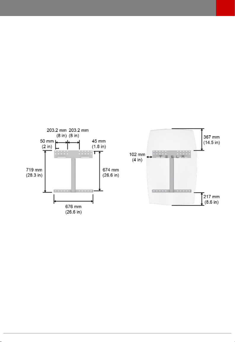
STEP 9 - DETERMINE THE MOUNTING LOCATION FOR POWERWALL
1. Using the wall mount bracket as a guide, measure the proposed location for Powerwall. The
bracket must be bolted into studs or a load-bearing wall, and allow clearance on all sides as
shown in Site Requirements.
2. If mounting into wood, use a stud finder to locate and mark the center of the wooden studs. It
is important to install each fastener as close to the middle of each stud as possible.
3. Position the thicker part of the bracket at the top, so that the
Use the bracket as a guide to mark the location of the holes on the wall. Space the holes 200,
300, 400, 500, or 600 mm (8, 12, 16, 20, or 24 in) apart.
Note: Use a level tool to ensure that the bracket is level.
STEP 10 - INSTALL THE WALL MOUNT BRACKET
1. Drill the pilot holes to attach the wall mount bracket to the wall.
2. Install at least four washers and fasteners into the top part of the bracket and two washers
and fasteners into the bottom of the bracket. There must be at least one fastener in each of
the six mounting hole rows. Install the fasteners in the order shown in the numbered image.
flat side is flush with the wall.
3. Verify that the bracket is firmly attached to the wall.
4. For easier alignment while lifting, use tape or a pencil to mark:
• The wall at the height of the bracket lip, on the outside edges of the intended mount
point
• The Powerwall box sides, at the level of the mounting cleat
• The centerlines of both the box and the bracket
Tesla Energy 19
Page 22

Step-by-Step Installation Instructions
STEP 11 - MOUNT POWERWALL
1. With Powerwall still in its box, keeping it as level as possible, lift it so that the mounting cleat
is just above the lip on the wall mount bracket. Use the tape or pencil marks on the wall as
visual guides.
2. Lower Powerwall so that the cleat on the back of Powerwall fits securely over the lip on the
bracket.
3. Ensure that Powerwall is centered on the bracket. When properly centered, Powerwall sits
between the two protruding tabs on the bottom part of the bracket.
20 Powerwall Installation Manual
Page 23

Step-by-Step Installation Instructions
STEP 12 - REMOVE THE PACKAGING
Note: Two people are needed for this procedure.
1. First person: Hold the box in place from the bottom edge, to prevent the box from slipping
and damaging Powerwall's front cover.
2. Second person: Use a T20 Torx to remove the 8 screws holding the box to the wooden blocks.
3. Being careful not to bump the box into the sides or edges of Powerwall's front cover, remove
the box and carefully set it aside.
Note: Leave the protective sticker on the Powerwall front cover until installation is complete.
4. Use a 17 mm socket to remove the 4 bolts that hold the wooden spacer blocks against the
sides of Powerwall. Remove all 4 wooden blocks.
5. Use a T30 Torx driver to remove the screws from the metal L-brackets and discard.
6. Use a 10 mm socket tool and the 2 provided M6 external hex bolts to secure Powerwall to the
lower tabs of the wall mount bracket. Torque to 7 Nm (62 in-lbs).
Tesla Energy 21
Page 24

Step-by-Step Installation Instructions
STEP 13 - FEED WIRES THROUGH THE CONDUIT PLATE OR CABLE GLAND
Depending on regional requirements, Powerwall can be installed either through conduit or
through a cable gland. Follow local codes to determine which is appropriate.
The conduit plate hole has a 28.2 mm (1.11 in) diameter. It supports ¾” trade fittings, and PG-21 and
M25 glands. The conduit plate has passed water ingress testing with individual cables squeezed
together in a single gland. All fittings other than the conduit plate itself are provided by the
installer.
The access point on Powerwall is centered on the bottom of the device.
1. Use a T30 Torx driver to remove the conduit plate.
2. For conduit configurations, feed the wires through the conduit and conduit opening. Make
sure that wires are not frayed.
3. For cable gland
the gland. Make sure that wires are not frayed.
4. Tighten the gland or conduit opening to the housing plate.
5. Reattach the conduit plate to Powerwall and torque to 7 Nm (62 in-lbs).
22 Powerwall Installation Manual
configurations, push out the protective coverings and feed the wires through
Page 25

Step-by-Step Installation Instructions
STEP 14 - CONNECT MULTIPLE POWERWALLS TOGETHER
If the site is installing multiple Powerwalls, follow these instructions for wiring the units. If not, skip
to the next step.
Caution: Do not splice wiring inside Powerwall.
Note: Ensure that the multi-Powerwall installation meets local requirements for DC disconnects
and correctly rated overcurrent protection.
Note: Always check with the inverter partner for inverter abilities and instructions before
connecting multiple Powerwalls.
1. Remove the splash cover as described above.
2. Verify that the communication and address switch settings for each Powerwall in the chain are
accurate as described in the above steps.
3. Connect the wiring coming from the inverter (communications +/-, enable line, and 12V Logic
+/- wires) to the J7 connector as the primary connector.
4. Connect the output communications, enable, and 12V logic wiring going toward the next
Powerwall to the J6 connector (see previous circuit board image). Powerwall allows daisy
chaining of low voltage and communication cables.
5. Run DC power wiring independently to each Powerwall. Fuse each Powerwall individually.
6. Reinstall the splash cover.
STEP 15 - CONNECT POWERWALL TO THE INVERTER
Run the wires between Powerwall and the inverter as described in the inverter manual. Follow
local electrical installation codes for wire installation.
Note: Ensure that the installation meets local requirements for DC disconnects and correctly rated
overcurrent protection.
Tesla Energy 23
Page 26

Step-by-Step Installation Instructions
STEP 16 - ATTACH THE SIDE COVERS
Caution: Failure to install the side covers using the proper steps might result in permanent
damage to the covers.
1. Remove the side covers and the bag of enclosed fasteners from the shipping box.
2. Position the first side cover to the side of Powerwall that matches its curve.
3. Angle the back edge (side closest to the wall) in toward Powerwall.
4. Insert the top edge of the cover, then push in to fasten the top spring clip.
5. Fasten the bottom spring clip second, for easiest
6. Fasten the middle spring clip. Verify that the entire length of the side cover is tucked
completely under the edge of the front cover.
7. Repeat the installation steps on the opposite side for the other side cover.
fit.
24 Powerwall Installation Manual
Page 27

Step-by-Step Installation Instructions
STEP 17 - ATTACH THE BOTTOM COVER
1. Line up the bottom cover with the bottom of Powerwall, between the side covers.
2. Tuck the back edge of the bottom cover (closest to the wall) under the metal edge of the
Powerwall body.
3. Route the wires to run from the conduit plate or gland back (toward the wall) below the
ground/earth lug, then forward again to match the internal wiring harness path under the
splash cover into the circuit board. Verify that the wires are not pinched or kinked by the
internal edge of the bottom cover.
4. Close the bottom cover carefully over the wiring. Verify that the edge of the bottom cover is
tucked completely under the lip of the front cover.
5. Use a 10 mm hex socket to attach the bottom cover with an M6 screw on each side. Torque to
3 Nm (27 in-lbs).
6. Once installation is complete, gently peel the protective sticker from Powerwall's front cover.
STEP 18 - REPACK THE SHIPPING BOX
All Powerwall packing material is recyclable. To facilitate this process, place the packing materials
into the shipping box in reverse order and return the shipping box to the Tesla Energy Authorized
Reseller, or recycle onsite as appropriate.
Tesla Energy 25
Page 28

Operation and Care
NORMAL OPERATION
During normal operation, Powerwall is completely controlled by the inverter. If Powerwall and the
inverter are installed correctly, the inverter can turn on Powerwall, begin communications, then
begin to process power commands. See the inverter manual for further configuration instructions.
Warning: Do not operate Powerwall unless all covers are in place.
Warning: Do not disconnect anything from or add anything to Powerwall.
Caution: Do not try to communicate with Powerwall using third party tools or diagnostics
between Powerwall and the inverter.
Caution: Do not lean on, stack anything on top of, or hang anything from Powerwall or the
conduit.
POWERWALL CARE
Keep the top edge of Powerwall clear of leaves and other debris if installed outside, to maintain
optimal
airflow.
To clean Powerwall, use a soft, lint-free cloth. The cloth can be dampened with only water if
needed.
Caution: Do not use cleaning solvents to clean Powerwall.
TROUBLESHOOTING
If Powerwall is not working correctly, perform the following steps. Powerwall is not user
serviceable and must be repaired by a Tesla Energy Certified Installer who has been trained by
Tesla.
• Check the screen or portal of the inverter to look for fault codes and descriptions.
• If Powerwall refuses to operate: check the temperature in the room and increase ventilation if
needed.
• If the inverter and Powerwall are both unresponsive:
1. Switch
2. Switch o the AC and DC breaker(s) (if applicable) for the inverter.
3. Wait for at least one minute.
4. Turn AC and DC breakers back on (if applicable).
5. Turn the inverter back on.
• If a brownout or blackout is experienced during backup: reduce the loads and check that the
breakers have not opened.
• If it is not possible to communicate with the inverter through its portal: ensure that the home
Internet connection is working.
• Follow the troubleshooting steps outlined in the inverter manual for both Powerwall and the
overall system.
If the issue persists, contact the Tesla Energy Authorized Reseller who originally sold the
Powerwall.
o the inverter (if it has a switch).
26 Powerwall Installation Manual
Page 29

What to Do in Case of an Emergency
In the event of any threat to health or safety, always begin with these two steps before addressing
the other suggestions below:
1. Immediately contact the fire department or other relevant emergency response team.
2. Notify all people who might be aected and ensure that they are able to evacuate the area.
Warning: Only perform the suggested actions below if it is safe to do so.
• In case of a fire:
• Switch o the inverter (if it has a switch), then the AC breaker to the inverter.
• If a disconnect exists, switch
• Acceptable fire extinguisher types are water, CO2, and ABC. Avoid type D (flammable
metal) extinguishers.
• In case of flooding:
• Stay out of the water if any part of the battery, inverter, or wiring is submerged.
• Switch
• If a disconnect exists, switch o the DC disconnect on the inverter.
• If possible, protect the system by finding and stopping the source of the water, and
• Let the area dry completely before use.
• If there is an unusual smell or smoke:
• Switch
• If a disconnect exists, switch
• Ensure nothing is in contact with Powerwall.
• Ventilate the room.
• Contact the Tesla Energy Authorized Reseller who sold the Powerwall.
• If Powerwall is leaking coolant:
• Switch o the inverter (if it has a switch), then the AC breaker to the inverter.
• If a disconnect exists, switch
• Ventilate the area.
• Contact the Tesla Energy Authorized Reseller who sold the Powerwall.
When cleaning up spilled coolant:
• Wear safety goggles, rubber gloves, pants, a long sleeved shirt, and fully closed shoes.
• Avoid further coolant spill by putting a bucket under the leak. Powerwall holds up to 1.6 L
• Pour cat litter, sawdust, or another absorbent material on the spill immediately. Allow the
• Use paper towels to collect the material that was used and discard the soiled paper
• Clean up anything that remains using soap and warm water.
• If Powerwall is making unusual noises:
• Switch
• If a disconnect exists, switch
• Ensure that nothing is in the vent on top of Powerwall or in the fan.
• If nothing was found, contact the Tesla Energy Authorized Reseller who sold the
o the inverter (if it has a switch), then the AC breaker to the inverter.
pumping water away.
o the inverter (if it has a switch), then the AC breaker to the inverter.
Warning: According to the U.S. Environmental Protection Agency, coolant can be
absorbed through the skin and cause damage to internal organs. Ensure that it does not
touch or enter any part of the body including, but not limited to, skin, eyes, and mouth.
(1.69 qt) of coolant.
material to absorb as much of the coolant as possible.
towels in a sealed plastic bag. Place the sealed plastic bag into the garbage.
o the inverter (if it has a switch), then the AC breaker to the inverter.
Powerwall.
o the DC disconnect on the inverter.
o the DC disconnect on the inverter.
o the DC disconnect on the inverter.
o the DC disconnect on the inverter.
Tesla Energy 27
Page 30

3500 Deer Creek Road
Palo Alto, CA 94304
Rev. 1.02 May 16, 2016
 Loading...