

Page 1
Gen 3 Wall Connector Manual
Type 2 Handle, Three Phase
Page 2

Important Safety Information........................... 2
Product Specifications.........................................5
Wall Connector Label...........................................6
Power Supply Options.........................................7
Circuit Breaker Rating / Maximum Output.....
.....................................................................................10
Using Wall Connector......................................... 12
Features................................................................... 13
Connectivity............................................................................13
Hosted Access Point............................................................13
Local Network........................................................................13
Residual Current Device (RCD).......................................14
Ground Monitor Interrupter.............................................. 14
Power Outages...................................................................... 15
Firmware Updates................................................................ 15
Thermal Monitoring..............................................................15
Wall Connector External Components.........16
Wall Connector Internal Components..........17
In the Box................................................................ 18
Tools.......................................................................... 19
Installation Considerations..............................20
Installation Steps................................................. 23
STEPS 1, 2, 3: Preparing and Mounting the Wirebox...
.................................................................................................... 23
STEP 4: Sizing and Routing Conductor Wires..........25
STEP 5: Stripping and Securing Wires in Wirebox
Terminals................................................................................. 26
STEP 6: Securing Main Unit to Wirebox......................28
Commissioning Procedure...............................29
Wall Connector LEDs..........................................31
Light Codes.............................................................................31
Error Codes............................................................................32
Warranty Information........................................ 33
Limits of Liability.................................................34
Dispute Resolution..............................................35
UK Earthing Application Note........................3
8
Page 3
IMPORTANT SAFETY INFORMATION
Read all instructions before using this product. Save these instructions. Wall Connector features built-in RCD
Type A + DC 6mA.
This manual contains important instructions for the Tesla Gen 3 Wall Connector that shall be followed during
installation, operation, and maintenance. Please review all warnings and cautions before installing and using
the Wall Connector.
WARNING: When using electric products, basic precautions should always be followed, including the
following.
INSTRUCTIONS RELATING TO RISK OF FIRE OR ELECTRIC SHOCK
WARNING: Do not install or use the Wall Connector near flammable, explosive, harsh, or combustible
materials, chemicals, or vapors.
WARNING: Turn o power at the circuit breaker before installing or cleaning the Wall Connector.
WARNINGS
WARNING: This device should be supervised when used around children.
WARNING: The Wall Connector must be earthed through a permanent wiring system or an
equipment-earthing conductor.
WARNING: Use the Wall Connector only within the specified operating parameters.
WARNING: Never spray water or any other liquid directly at the wall mounted control box. Never
spray any liquid onto the charge handle or submerge the charge handle in liquid. Store the charge
handle in the dock to prevent unnecessary exposure to contamination or moisture.
WARNING: Do not use the Wall Connector if it is defective, appears cracked, frayed, broken, or
otherwise damaged, or fails to operate.
WARNING: Do not use the Wall Connector if the flexible power cord or cable is frayed, broken, or
otherwise damaged, or fails to operate.
WARNING: Do not attempt to disassemble, repair, tamper with, or modify the Wall Connector. The
Wall Connector is not user serviceable. Contact Tesla for any repairs or modification.
WARNING: When transporting the Wall Connector, handle with care. Do not subject it to strong force
or impact or pull, twist, tangle, drag, or step on the Wall Connector, to prevent damage to it or any
components.
WARNING: Do not touch the Wall Connector’s end terminals with fingers or sharp metallic objects,
such as wire, tools, or needles.
2Gen 3 Wall Connector Manual
Page 4

IMPORTANT SAFETY INFORMATION
WARNING: Do not insert fingers or foreign objects into any part of the Wall Connector.
WARNING: Do not forcefully fold or apply pressure to any part of the Wall Connector or damage it
with sharp objects.
WARNING: Use of the Wall Connector may aect or impair the operation of any medical or
implantable electronic devices, such as an implantable cardiac pacemaker or an implantable
cardioverter defibrillator. Check with your electronic device manufacturer concerning the eects that
charging may have on such electronic devices before using the Wall Connector.
3Gen 3 Wall Connector Manual
Page 5
IMPORTANT SAFETY INFORMATION
CAUTIONS
CAUTION: Do not use private power generators as a power source for charging.
CAUTION: Incorrect installation and testing of the Wall Connector could potentially damage the
vehicle's battery, components, and/or the Wall Connector itself. Any resulting damage is excluded
from the New Vehicle Limited Warranty and the Charging Equipment Limited Warranty.
CAUTION: Do not operate the Wall Connector in temperatures outside its operating range of -30˚ C
to 50˚ C (-22˚ F to 122˚ F).
CAUTION: Wall Connector should only be installed by personnel who are trained and qualified to
work on electrical systems.
CAUTION: Ensure that Wall Connector is within storage temperature when moving, transporting, or
storing.
4Gen 3 Wall Connector Manual
Page 6

PRODUCT SPECIFICATIONS
This manual applies to Wall Connectors identified by part number 1529455-**-*.
Voltage and Wiring
1-phase 230 V L-N
3-phase 230 V L-L
3-phase 400 V L-L
Current Output Range Maximum 32 A (adjustable by installer)
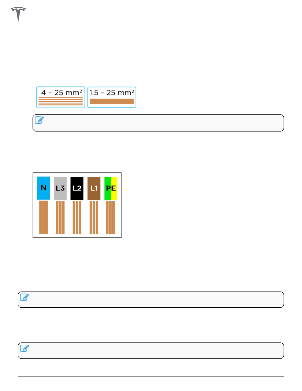
Terminal Blocks
Stranded: 4-25 mm2, copper only
Solid: 1.5-20 mm2, copper only
Supported Earthing Scheme TN/TT/IT
Frequency 50/60 Hz
Cable Length 7.3 m (24 ft) or 2.6 m (8.5 ft)
Wall Connector Dimensions
Height: 345 mm (13.6 in)
Width: 155 mm (6.1 in)
Depth: 110 mm (4.3 in)
Wire Box Bracket Dimensions
Height: 250 mm (9.8 in)
Width: 120 mm (4.7 in)
Depth: 50 mm (2.0 in)
Weight (including wirebox) 6.8 kg (15 lb)
Operating Temperature -30˚C to 50˚C (-22˚F to 122˚F)
Storage Temperature -40˚C to 85˚C (-40˚F to 185˚F)
Enclosure Rating IP 55
Ventilation Not required
Means of Disconnect External branch circuit breaker
Residual Current Detection Integrated (Type A + DC 6 mA)
Wi-Fi 2.4 GHz, 802.11b/g/n
Certifications CE, IEC 61851-1 CB
5Gen 3 Wall Connector Manual
Page 7
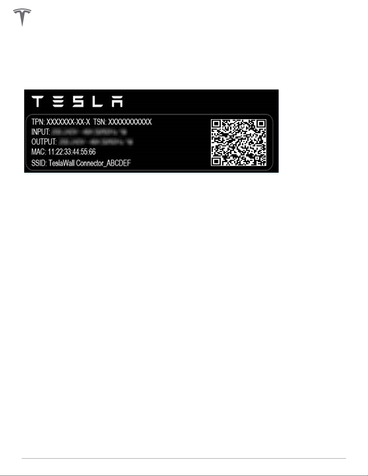
WALL CONNECTOR LABEL
Each Wall Connector has a label on the exterior side with information that is unique to the product,
including:
• TPN: Tesla Part Number
• TSN: Tesla Serial Number
• Input: Max input power
• Output: Max output power
• MAC: Unique MAC address assigned to the Wall Connector
• SSID: Unique Wi-Fi access point assigned to the Wall Connector
6Gen 3 Wall Connector Manual
Page 8
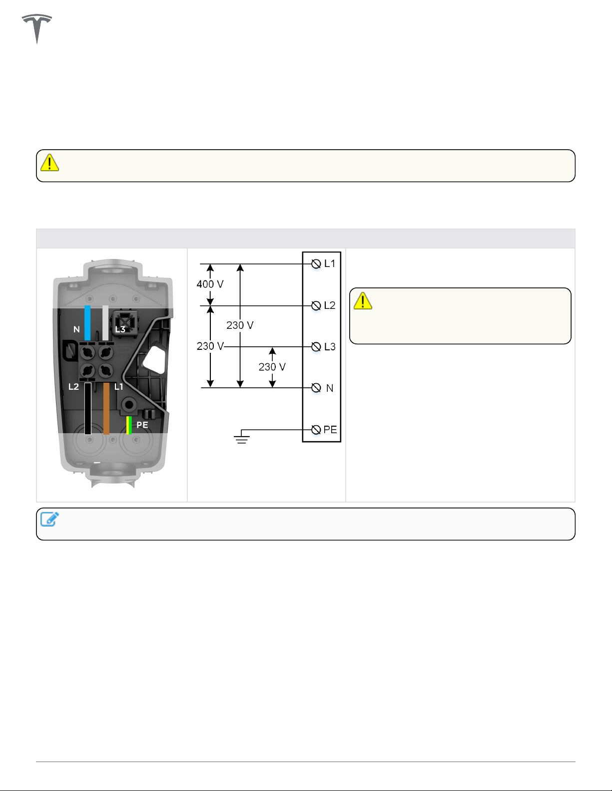
POWER SUPPLY OPTIONS
For basic operation, Wall Connector requires an electrical connection to Line 1, Neutral, and Protective Earth
(PE) terminals. Connection to Line 2 and Line 3 terminals is supported for some grid types.
CAUTION: Wall Connector supports 230 V L-N (+/- 10%). Mis-wiring the neutral terminal with >264V
to PE can damage Wall connector
Wall Connector can operate on a three-phase power supply or a single-phase power supply.
Table 1. Most Common Installation Option
Wiring Configuration Option for Five Wires: Line 1, Line 2, Line 3, Neutral, PE
Grid type options:
• 400 V 3-phase wye
CAUTION: Double check N
connection is 230 V L to N at
terminals of wirebox before
energizing.
NOTE: Blue is used as the IEC standard for neutral. Some markets may use other colors to symbolize
neutral and line conductors.
7Gen 3 Wall Connector Manual
Page 9
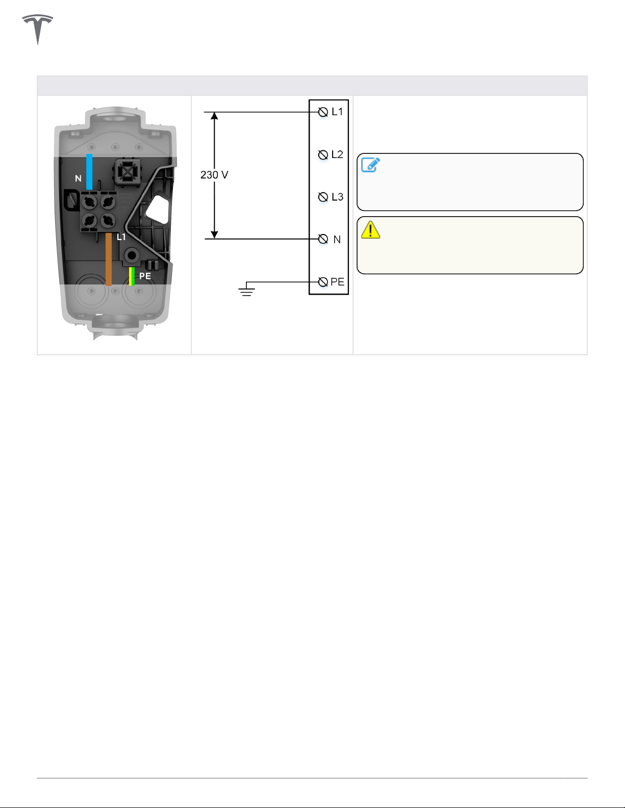
POWER SUPPLY OPTIONS
Table 2. 2nd Most Common Installation Option
Wiring Configuration Option for Three Wires: Line 1, Neutral, PE
Grid type options:
• 230 V Line to Neutral
• 230 V Line to Line
NOTE: For 230V Line to Line
connections, without a Neutral,
connect one Line from the grid to the
Neutral terminal of the wirebox
CAUTION: Double check N
connection is 230 V L to N at
terminals of wirebox before
energizing.
8Gen 3 Wall Connector Manual
Page 10
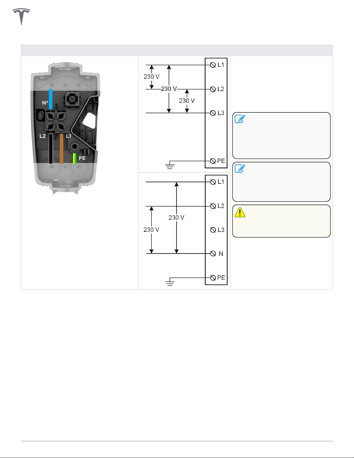
POWER SUPPLY OPTIONS
Table 3. Least Common, but Supported Installation Option
Wiring Configuration Option for Four Wires: Line 1, Line 2, Neutral, PE
Grid type options:
• Delta 230 V Line to Line
• Open wye with 230 V Line
to Neutral
• Split phase 230 V Line to
Neutral
NOTE: In the case of a
Delta grid connection, land
one of the line conductors
from the grid in the neutral
terminal of Wall Connector
wirebox.
NOTE: The conductor with
lowest voltage to
Protective Earth (PE)
should be connected to
the Neutral terminal.
*When connecting to a 230 V delta no
neutral grid, land one of the line
connections in the neutral terminal of
the wirebox.
CAUTION: Double check N
connection is 230 V L to N
at terminals of wirebox
before energizing.
9Gen 3 Wall Connector Manual
Page 11
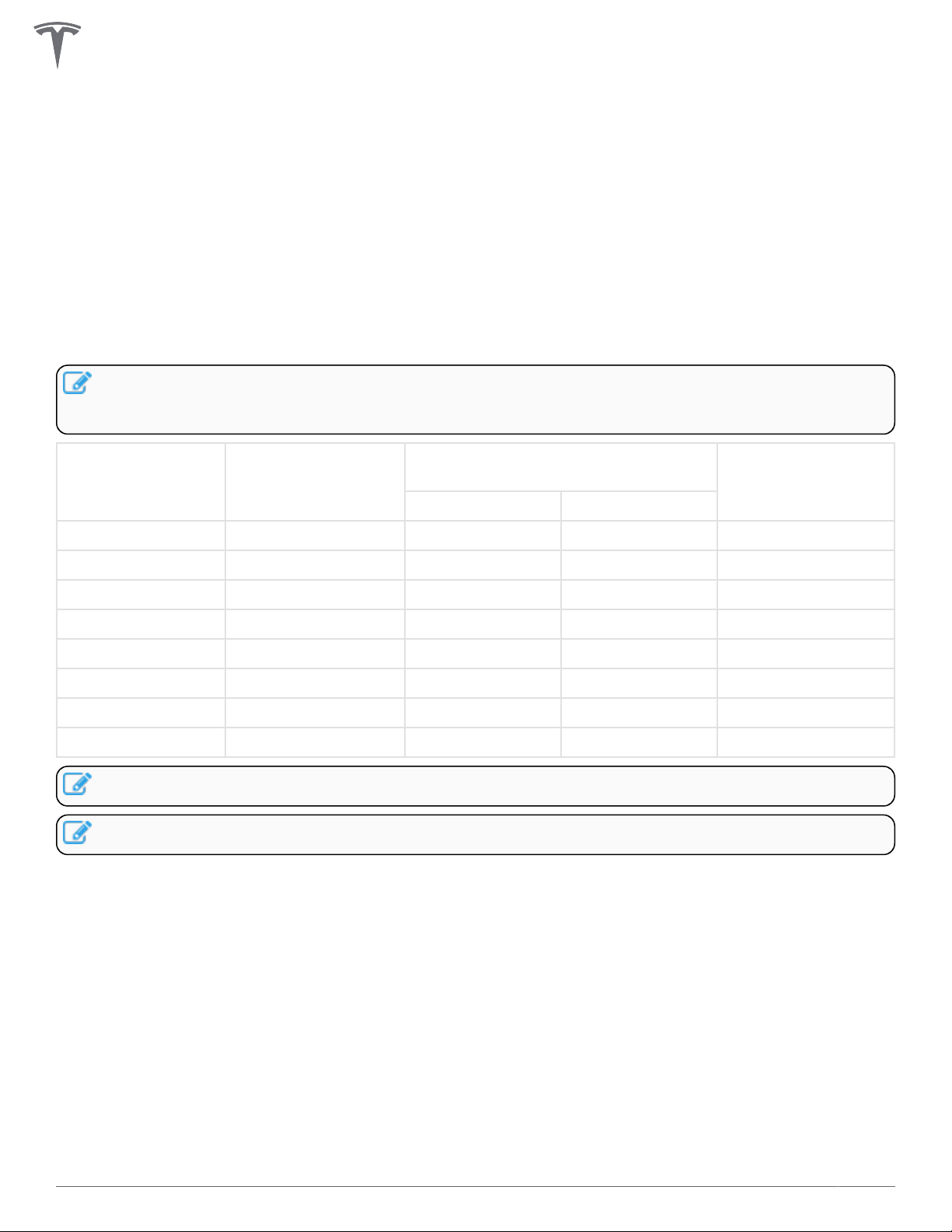
CIRCUIT BREAKER RATING / MAXIMUM OUTPUT
Power Output
For the best charge rate, install a circuit breaker to match the grid type and desired current output. Wall
Connector features built-in RCD Type A + DC 6mA.
Maximum current output (amps) can be programmed by the installer as part of the commissioning process.
Any amperage between 6 A and 32 A can be selected. Estimate power output for various grid connections
below:
NOTE: Some Tesla vehicles may draw less current than the max output of Wall Connector. Actual
charging rate depends on Wall Connector output and onboard charger in the vehicle. See Tesla
website for vehicle specifications.
Maximum current
output (A)
32 7.4 8.5 11 22.1
25 5.8 6.6 10 17.3
20 4.6 5.3 8 13.8
16 3.7 4.2 6.4 11
13 3 3.5 5.2 9
10 2.3 2.7 4 6.9
8 1.8 2.1 3.2 5.5
6 1.4 1.6 2.4 4.1
NOTE: Refer to local regulations regarding any disconnect requirements.
NOTE: See Commissioning Procedure on page 29 for details on how to set maximum amperage.
230 V Single-phase
power output (kW)
230 V Three-phase delta power
output (kW)
Model S/X Model 3/Y
400 V Three-phase
power output (kW)
10Gen 3 Wall Connector Manual
Page 12
CIRCUIT BREAKER RATING / MAXIMUM OUTPUT
Branch Circuit Conductors and Earth Wire
• Refer to local electrical code to select correct conductors and earth wire size that are suitable for the
chosen circuit breaker.
• Wall Connector wirebox terminals can accept stranded wire sized between 4 mm2 to 25 mm2, or solid
wire 1.5 mm2 to 25 mm2. Installer is responsible for selecting a wire size that will be compliant with
local code, possibly taking into account amperage, distance and other site conditions.
NOTE: If using stranded wiring smaller than 4 mm2, use a correctly sized ferrule so it can be
securely terminated.
• For sites with multiple Wall Connectors, each Wall Connector must have its own branch circuit and
dedicated circuit breaker.
• For outdoor installations, use watertight fittings when securing feeder wires to the wirebox.
• For this installation guide, IEC standard colors are used for L1, L2, L3, Neutral, and PE. Some regions
may use other standardized colors.
Earth Connections
Wall Connector must have an earth path back to the main equipment earthing point on site. Without a
proper earth connection, the Wall Connector will not charge a vehicle during an earth assurance test.
Equipment-earth conductor must be run with the circuit conductors and connected to the equipment-earth
terminal in the wirebox. Install a earth wire sized according to local electrical code.
NOTE: To support TT and IT grids, earth assurance can be disabled as part of the commissioning
process. Earth assurance must always be enabled for TN grids.
Additional requirements apply to UK properties fed from a TN-C-S supply. In most scenarios, these
properties will require an external device which provides PEN fault detection and isolation in accordance
with BS 7671. It is the responsibility of the installer to ensure that the requirements of BS7671 are met please refer to Tesla's application note at the end of this manual that discusses this topic in more detail.
NOTE: The use of an dedicated earth rod for the EVSE will not generally be a practical solution to
meet the BS 7671 requirements
11Gen 3 Wall Connector Manual
Page 13
USING WALL CONNECTOR
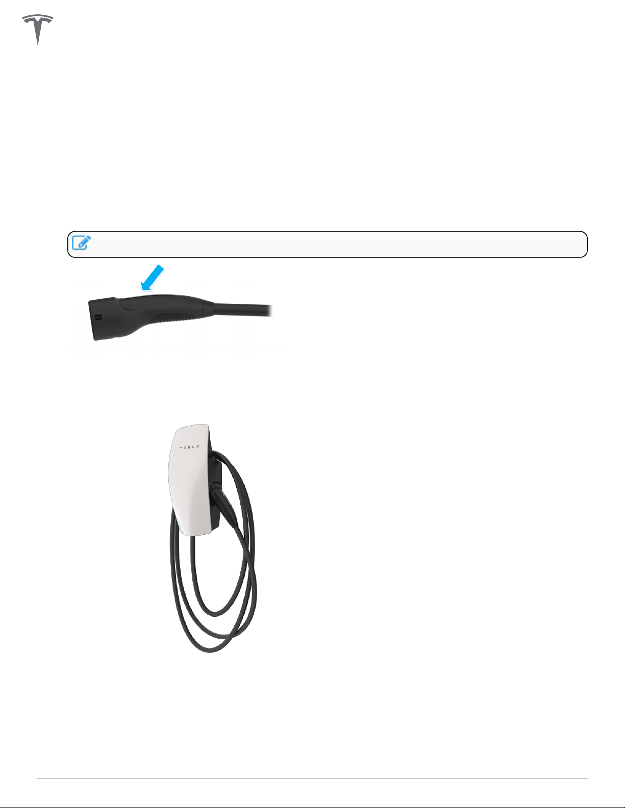
1. Open the vehicle charge port by pressing the button on the charge handle, pressing on the charge
port door, using the mobile app, using the vehicle touchscreen, or by pressing and holding the trunk
button on the keyfob.
2. Insert the charge handle into the vehicle charge port.
3. Check the vehicle controls to verify charging.
4. To remove the charge handle from the vehicle, press and hold the button on the handle to unlock the
charge port.
NOTE: The vehicle must be unlocked for the charge handle to be removable.
5. Remove the charge handle from the vehicle charge port.
6. Wrap the charge cable counter-clockwise around the Wall Connector and insert the charge handle into
the holster.
12Gen 3 Wall Connector Manual
Page 14
FEATURES
Connectivity
Wall Connector is equipped with Wi-Fi to communicate with local site routers, vehicles, mobile devices,
other Wall Connectors, and other Tesla products.
Hosted Access Point
Wall Connector hosts a WPA2 password-secured, 2.4 GHz, 802.11 Wi-Fi access point network to facilitate
commissioning and connecting to other devices.
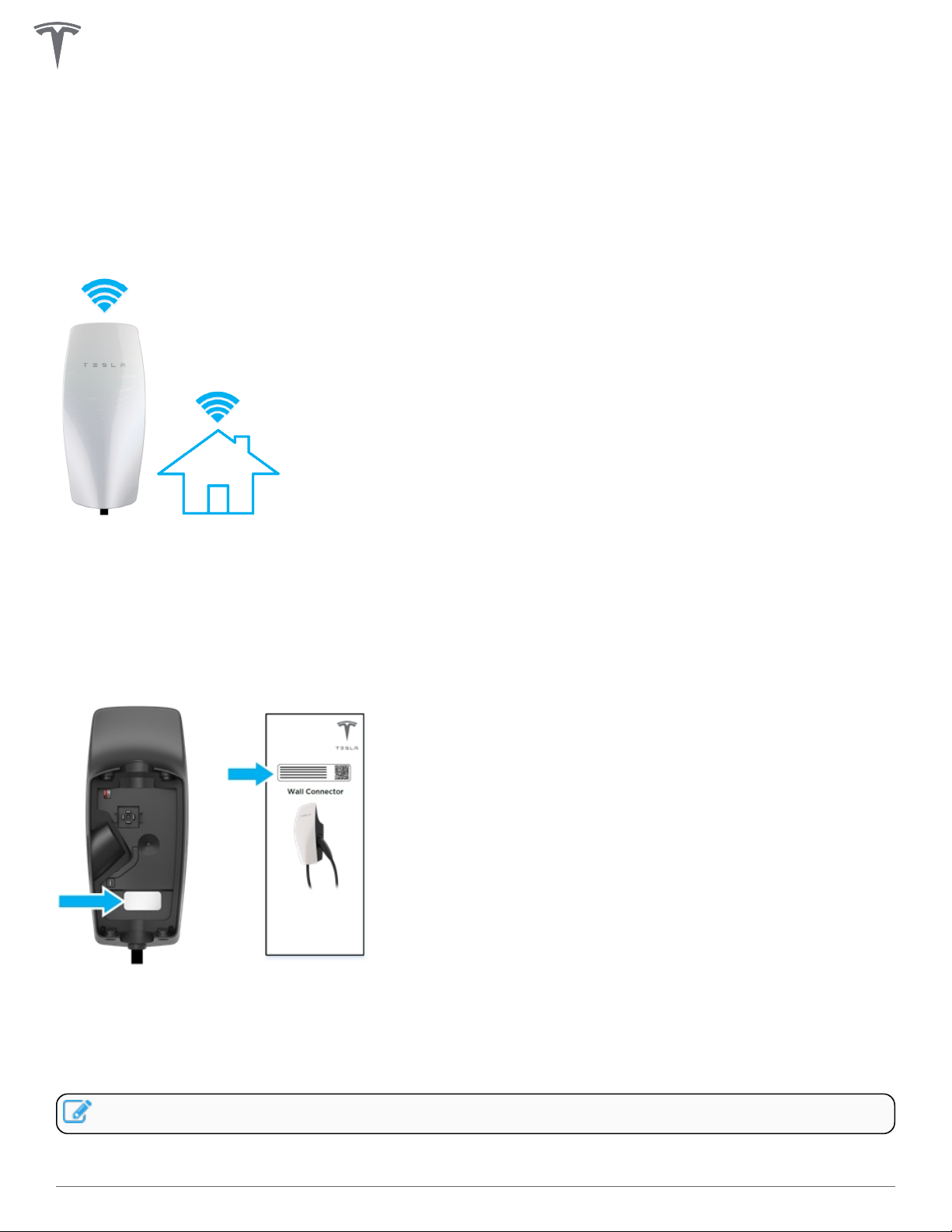
A unique SSID Wi-Fi network name and WPA2 password for connecting to the Wall Connector are printed
on a label at the rear of the main unit, as well as on the front cover of the Quickstart Guide included in the
box.
Local Network
Connecting Wall Connector to a local Wi-Fi network enables it to receive over-the-air firmware updates,
remote diagnostics access, and usage data tracking capability. A Wi-Fi connection is required for sites that
utilize authentication, billing, and other property management features.
NOTE: Some features will be added over time.
Wall Connector only supports WPA2/3-secured, 2.4 GHz, 802.11 infrastructure mode networks.
13Gen 3 Wall Connector Manual
Page 15

FEATURES
NOTE: Hidden networks are supported.
NOTE: WPA enterprise will be supported in a future firmware update.
NOTE: Property management features will be enabled via future firmware updates.
Residual Current Device (RCD)
Wall Connector features built-in RCD Type A + DC 6mA. The benefit of this protection is that RCD Type B
are not required when installing Gen 3 Wall Connectors, consult local regulations on the type of breaker
required.
AC earth fault interruption automatically detects an AC current mismatch between power delivery
conductors that would indicate that current is flowing through the earth conductor. AC fault protection will
trip at 20 mA.
DC earth fault interruption automatically detects DC leakage through earth. DC fault protection will trip at 6
mA.
User interaction such as pressing the cable button or unplugging from vehicle is required to clear this fault. If
fault continues, consult with an electrician to review power supply.
Ground Monitor Interrupter
The ground monitor interrupter allows the installer to select dierent early monitor options. Wall Connector
continuously checks for the presence of a safe earth connection and automatically recovers from faults.
Earth assurance operates by injecting a small amount of current into the earth conductor in order to
measure the impedance between line and earth. If high impedance is detected, the Wall Connector will lock
out charging and display a error code of two (2) red blinks. See Error Codes on page 32 for a full list of
error codes.
For earth assurance to operate on TN grids, one leg of the distribution transformer must be earth-bonded
(Neutral). Earth bond should only occur at one location in a site's electrical system.
Wall Connector earth assurance may be adjusted in countries with TT or IT grid configurations.
The Earth Monitor Interrupter feature monitors the Wall Connector earth connection. Select the correct
option based on the installation's earthing system and earth impedance.
Depending on country, three options are available:
• Enable: Earth connection will be monitored and a high detected earth resistance will disable the Wall
Connector. This is the preferred setting to provide protection, and should be selected where earth
connection is expected to be strong (as in the case on TN networks and most TT networks), and
where required by regulation.
• Disabled: Earth connection will not be monitored. This should be selected where the earth connection
is not made (as is the case for IT networks), or where the current induced by this check would be
problematic (as is the case on some TT networks with sensitive residual-current devices).
NOTE: Earth Monitoring is always enabled for installations in North America.
Temporary problems such as earth faults or utility power surges are resolved automatically.
14Gen 3 Wall Connector Manual
Page 16

FEATURES
Power Outages
If there is a power outage while Wall Connector is charging a vehicle, charging will automatically resume
within 1 to 3 minutes after power restoration. The Wall Connector will display a solid blue light on the
faceplate to indicate that it is communicating with the vehicle and waiting to resume charging. Alternatively,
pressing the button on the charge handle after power restoration will cause Wall Connector to resume
charging immediately.
Firmware Updates
Firmware updates will be automatically applied to the Wall Connector to improve the user experience and
introduce new features. Connect Wall Connector to Wi-Fi for access to the most recent firmware update. See
Commissioning Procedure on page 29.
Thermal Monitoring
Wall Connector actively monitors temperatures in multiple locations while charging to ensure stability of the
charge session. Temperature sensors are located at the relays, microcontroller, charge handle, and rear of the
main unit to monitor the temperature of the terminals in the wirebox.
In warmer conditions, Wall Connector may reduce current and charge speed to protect itself. When this
happens, the light bar on the faceplate will continue to display the “streaming green” and a blink code of
three red flashes to indicate that charging has been reduced due to high temperatures. If heat continues to
rise, Wall Connector will stop charging and display a blink code of three red flashes.
NOTE: See Error Codes on page 32 for full list of error codes.
For optimal performance, install Wall Connectors in areas where ambient temperature will remain below
50˚C (122˚F). In rare circumstances, Wall Connector may begin reducing amperage at 35˚C (95˚F) ambient
temperatures. Adjustments to amperage are automatic and do not require user input; Wall Connector will
return to starting current when temperatures are reduced.
15Gen 3 Wall Connector Manual
Page 17

WALL CONNECTOR EXTERNAL COMPONENTS
"Wall Connector" refers to the product as a whole.
1. Faceplate
2. Light bar (vertical)
3. Main unit
4. Charge handle button
5. Charge handle
16Gen 3 Wall Connector Manual
Page 18

WALL CONNECTOR INTERNAL COMPONENTS
1. Contact blades
2. Temperature sensor
3. Conductor terminals
4. Zip tie anchor
5. Sliding contacts
6. Wirebox drainage opening (enables protection)
7. Neutral
8. Line 1
9. Line 2
10. Line 3
11. Earth
17Gen 3 Wall Connector Manual
Page 19

IN THE BOX
Hex Bit (4 mm)
Main Unit
Wirebox
Wall Connector-to-
Zip tie (x1)
NOTE: The hex bit, zip tie, and fasteners are located in a plastic bag inside the wirebox, which comes
attached to the main unit of the Wall Connector.
NOTE: Wall plugs are not included. If installing in concrete or other like materials, use 6 mm wall
plugs.
Wirebox Fastener (x4)
Wirebox Mounting Template
Wirebox-to-Wall Fastener
(x2)
4.0 x 50 mm (PZ2)
(#8 x 2 in)
Quickstart Guide (contains
sticker with SSID network
name and unique password)
18Gen 3 Wall Connector Manual
Page 20

Required Tools
NOTE: Drill bit sizes assume wood mounting surfaces. If installing on concrete or other masonry,
consult with an electrician for optimal pilot hole sizes.
TOOLS
Stud Finder
Torque Driver (5.6 Nm, 50 lbf . in)
Wire Stripper
Level
(If installing on wood walls)
Multimeter
Drill Bit, 5 mm (3/16 in)
(If installing on wood
walls)
Smartphone (with Wi-Fi) Power Drill
Drill Bit, 2.5 mm (3/32 in)
(If installing on wood walls)
Tape Measure
Bit Driver
Optional Tools
Step Bit, 29 mm (1-1/8 in) Step Bit, 35 mm (1-3/8 in)
Computer (with Wi-Fi)
19Gen 3 Wall Connector Manual
Page 21

INSTALLATION CONSIDERATIONS
Wall Connector may be installed on any flat, vertical surface capable of supporting its weight (e.g. wall,
pedestal, etc.). Wall Connector (wirebox, faceplate, and long cable) weighs 6.8 kg (15 lb).
Choosing Location
Install Wall Connector in a location that allows the charge cable to reach the vehicle charge port without
putting strain on the cable.
• Dark gray: Recommended installation area for Wall Connectors with 7.3 m (24 ft) cable
• Light gray: Recommended installation area for Wall Connectors with 2.6 m (8.5 ft) cable
Install Wall Connector in a location with ample clearance on all sides to allow the charge cable to loop
around the unit and the charge handle to comfortably land in the side dock.
NOTE: If constrained by space, a cable organizer can be installed near the Wall Connector.
20Gen 3 Wall Connector Manual
Page 22

INSTALLATION CONSIDERATIONS
Choosing Height
• Maximum height (indoor and outdoor): 1.52 m (60 in)
• Recommended height: ~1.15 m (~45 in)
• Minimum outdoor height: 0.6 m (24 in)
• Minimum indoor height: 0.45 m (18 in)
Maximizing Wi-Fi Signal Reception
Wall Connectors should be connected to a local Wi-Fi network for optimal functionality. For maximum signal
reception, avoid installing Wall Connector on opposite sides of concrete, masonry, metal studs, and other
physical obstructions that could impede Wi-Fi signal reception.
NOTE: If a mobile device is able to connect to local Wi-Fi at a given location, it is a good indication
that Wall Connector will also be able to connect.
21Gen 3 Wall Connector Manual
Page 23

INSTALLATION CONSIDERATIONS
Wire Entry Options
Wall Connector's wirebox has multiple wire entry options. Choose one entry path and follow installation
instructions based on chosen entry path.
1. Top entry location
2. Rear entry locations (left or right)
3. Bottom entry location
22Gen 3 Wall Connector Manual
Page 24

INSTALLATION STEPS
STEPS 1, 2, 3: Preparing and Mounting the Wirebox
This procedure has 4 dierent variations depending on the chosen wire entry option, but the general order
of steps will be the same for all wire entry options:
1. Drill 5 mm holes into the wirebox*. If wiring for rear entry, use step bit.
2. Use cardboard template to plan or drill pilot holes into mounting surface*. A 2.5 mm pilot hole is
recommended for most surfaces.
NOTE: Drill larger pilot holes that can accommodate 6 mm wall plugs if installing on concrete,
masonry, or similar materials.
NOTE: Installer can adjust pilot hole size based on mounting surface
NOTE: Use a level to ensure that the template is completely level.
3. Attach wirebox to mounting surface using included fasteners, which include an integrated sealing
washer. The fastener head is compatible with both #2 Phillips or #2 square head bit. Attach conduit/
fittings and bring in conductor wires*.
NOTE: It is the responsibility of the installer to select appropriate conduit/fitting materials for
the installation.
*Exact locations depend on the wire entry option
Table 4. For Top Wire Entry
For Top Entry 1 2 3
23Gen 3 Wall Connector Manual
Page 25

INSTALLATION STEPS
Table 5. For Bottom Wire Entry
For Bottom Entry 1 2 3
Table 6. For Rear Left Wire Entry
For Rear Left Entry 1 2 3
Table 7. For Rear Right Wire Entry
For Rear Right Entry 1 2 3
CAUTION: Wall Connector is IP 55 rated and does not need caulking. Refrain from using any bonding,
sealant, or adhesives as part of the Wall Connector installation. The provided screws have sealant
washers which provide adequate sealing.
Installer is responsible for providing appropriate glands, fittings, and conduit to secure incoming
power supply to Wall Connector wirebox. Top and bottom entry are 28 mm in diameter when sealing
plug is removed. If needed, bottom entry can be expanded using a step bit. Do not expand top entry.
24Gen 3 Wall Connector Manual
Page 26

INSTALLATION STEPS
STEP 4: Sizing and Routing Conductor Wires
Pull excess wire first, then cut to length. Use a wire stripper to cut each conductor wire appropriately based
on entry point and position. Attach the conduit/fittings and route each conductor wire into the wirebox so it
lands in the correct terminal.
NOTE: Insulation wire colors may vary based on market.
For Top Wire Entry
Wire lengths/proportions shown are not to scale.
For Bottom (1), Rear Left (2), or Rear Right (3) Wire Entry
Wire lengths/proportions shown are not to scale.
25Gen 3 Wall Connector Manual
Page 27

INSTALLATION STEPS
STEP 5: Stripping and Securing Wires in Wirebox Terminals
1. Use a wire stripper to strip the ends of each wire to ~12 mm.
2. Insert each stripped wire into the correct terminal.
NOTE: If using stranded wiring smaller than 4 mm2, use a correctly sized ferrule so it can be
securely terminated.
3. Use the included bit to torque each terminal to 5.6 Nm (50 lbf.in). Use zip ties to secure wires to
service loop on the left side of the wirebox.
26Gen 3 Wall Connector Manual
Page 28

INSTALLATION STEPS
4. Use scissors to cut excess plastic o zip tie after securing in place. Ensure no wiring or other
obstruction crosses over the terminal block screws before proceeding to the next step.
NOTE: Rear of Wall Connector has a sensor to monitor the terminal block, any obstruction from
wiring or zip tie can interfere with Wall Connector operation.
27Gen 3 Wall Connector Manual
Page 29

INSTALLATION STEPS
STEP 6: Securing Main Unit to Wirebox
1. Attach the main unit to the wirebox.
2. Secure the main unit to the wirebox with the 4 included fasteners using the included bit. Use a bit
driver to hand-tighten the fasteners.
28Gen 3 Wall Connector Manual
Page 30

COMMISSIONING PROCEDURE
The commissioning process for Wall Connector enables easy configuration of circuit breaker size, Wi-Fi
connectivity, and power sharing options. Wall Connectors must be commissioned before first use.
1. Turn on Wall Connector's corresponding circuit breaker to energize the unit.
2. Use a Wi-Fi-enabled device such as a smart phone to connect to the SSID Wi-Fi signal broadcasted by
the Wall Connector. Joining the Wall Connector network can be done by scanning the sticker QR code
on the Quickstart Guide cover page, or by manually selecting the network and typing in the WPA2
password (found on the sticker on the Quickstart Guide cover page).
NOTE: SSID will broadcast for 15 minutes.
NOTE: If you are unable to connect to the Wall Connector SSID, turn o the cellular data
function on your mobile device and try again.
NOTE: If the Wall Connector has not been commissioned, a solid yellow light will display on the
front of the main unit to indicate that it is ready to be commissioned.
3. Scan the QR code below with the device that is connected to the Wall Connector to access the web
browser commissioning interface. Alternatively, manually type the URL address (http://192.168.92.1)
into the web browser.
4. Follow the onscreen commissioning steps on the web browser.
29Gen 3 Wall Connector Manual
Page 31

COMMISSIONING PROCEDURE
NOTE: To have the Wall Connector broadcast the SSID again, hold the button on the charge
handle for 5 seconds or turn the circuit breaker o, then on again.
30Gen 3 Wall Connector Manual
Page 32

WALL CONNECTOR LEDS
Light Codes
Startup
Once energized at the circuit breaker, every LED (seven total) on the faceplate will illuminate for one second.
Other
After startup,
waiting for
commissioning
Solid yellow (green
+ red)
NOTE: If a red dot is displayed, connect to Wall Connector Commissioning or see next table for all
error codes.
Standby, waiting to
plug in
Top green solid
Charging in
progress
Every green
streaming
SSID broadcasting,
ready to
commission
Green pulsing Blue solid
Waiting to charge,
communicating
with vehicle
31Gen 3 Wall Connector Manual
Page 33

WALL CONNECTOR LEDS
Error Codes
All red blink codes pause for one second, and then repeat.
Light Bar What It Means Details
No Lights Power supply issue,
charging disabled
Solid yellow Wall Connector is ready
to be commissioned
Solid red Internal error, charging
disabled
Earth fault circuit
One (1) red
blink
Two (2) red
blinks
Three (3) red
blinks
interruption due to
unsafe current path,
charging disabled
Earth assurance fault,
high earth resistance
detected, charging
disabled
High temperature
detected; charging
limited or disabled
Verify that the power supply is turned on. If the issue persists,
have an electrician remove the Wall Connector from the wirebox
and confirm that voltage is present at the terminal block using a
multimeter. Record measurements at terminals of wirebox.
See Commissioning Procedure on page 29 to commission the
Wall Connector.
Turn the circuit breaker o, wait 5 seconds, and turn it back on. If
solid red light remains, document part number and serial number,
then contact Tesla Energy.
Inspect the handle, cable, Wall Connector, and vehicle charge
port for damage or signs of water ingress. Contact Tesla Energy if
power supply has been checked and confirmed as okay by an
electrician.
Verify that the Wall Connector is properly connected to earth.
The earth connection must be bonded in the upstream power
supply for proper operation. Check all physical connections,
including the wirebox terminals, electrical panel(s), and junction
boxes. If connected to a transformer, contact the transformer's
manufacturer for direction on how to bond the earth connection.
If charging on a IT or TT grid, check ground monitor settings.
Verify that Wall Connector is connected to Wi-Fi and updated
with the latest available firmware for optimal temperature
sensing functionality. Check the faceplate and cable handle for
excessive warmth. Have an electrician remove the Wall Connector
from the wirebox and verify that the conductors used are sized
correctly and that the terminal block is torqued to specification.
Four (4) red
blinks
Five (5) red
blinks
Six (6) red
blinks
Seven (7)
red blinks
Internet connection lost,
online features disabled
Power-sharing
communication issue,
charging reduced
Overvoltage or poor grid
quality detected,
charging disabled
Vehicle overcurrent
detected
Check for objects that could interfere with the area's Wi-Fi signal
strength. Confirm that the local Wi-Fi router is operational. If the
Wi-Fi password was changed recently, follow the commissioning
process on your mobile device to update the Wi-Fi settings.
Check for objects that could interfere with the area's Wi-Fi signal
strength. Follow the commissioning process on your mobile
device to re-link the Wall Connectors for power-sharing.
Connect to Wall Connector with commissioning process to view
live voltage info. If the issue persists, have an electrician remove
the Wall Connector from the wirebox and confirm that voltage
readings are as expected at the terminal block using a
multimeter. Record voltage readings at terminals.
Reduce the vehicle's charge current setting. If the issue persists
and the attached vehicle is manufactured by Tesla, record the
vehicle's VIN and approximate time of the fault and contact Tesla.
If the vehicle is not manufactured by Tesla, contact the vehicle's
manufacturer.
32Gen 3 Wall Connector Manual
Page 34

WARRANTY INFORMATION
Subject to the exclusions and limitations described below, the Charging Equipment Limited Warranty covers
the refund, repair or replacement necessary to remedy any manufacturing defects in a Tesla manufactured
and supplied Wall Connector that occur under normal personal use for a period of 48 months, or a period of
12 months for normal commercial use*, and a Tesla manufactured and supplied Mobile Connector or charging
adapter that occur under normal use for a period of 12 months, starting from the date of invoice to the
customer for any charging equipment. Any Tesla manufactured and supplied connector or adapter included
in the initial purchase and delivery of a Tesla vehicle by Tesla is covered under the Basic Vehicle Limited
Warranty section of the New Vehicle Limited Warranty for 4 years or 50,000 miles (80,000 km), whichever
comes first, subject to the terms and conditions of the New Vehicle Limited Warranty.
*For warranty claims specific to Wall Connectors, “commercial use” means Wall Connectors used for
purposes other than charging at a residential single family home for daily personal use, which includes, but is
not limited to, charging at hotels, oces, parking lots and complexes (including apartment, condominiums
and other multi-family or unit dwellings), and retail and other locations that allow (including by being listed
online or publicly) for pay-for-use charging, or are located where users other than the owner could
reasonably obtain access to the Wall Connector.
This Charging Equipment Limited Warranty does not cover any damage or malfunction directly or indirectly
caused by, due to, or resulting from, normal wear or deterioration, abuse, misuse, negligence, accident, lack
of or improper installation, use, maintenance, storage or transport, including, but not limited to, any of the
following:
Failure to follow the instructions, operation, maintenance and warnings published in the documentation
supplied with your Tesla connector or adapter;
External factors, including but not limited to, objects striking the Tesla connector or adapter, faulty or
damaged electrical wiring or connections, external electrical faults, junction boxes, circuit breakers,
receptacles or power outlets, the environment or an act of God, including, but not limited to, fire,
earthquake, water, lightning and other environmental conditions;
General appearance or damage to paint, including chips, scratches, dents and cracks;
Failure to contact Tesla upon discovery of a defect covered by this Charging Equipment Limited Warranty;
Any repair, alteration or modification to the Tesla connector or adapter or any part, or the installation or use
of any parts or accessories, made by a person or facility not authorized or certified to do so; and
Lack of or improper installation, repair or maintenance, including use of non-genuine Tesla accessories or
parts.
Although Tesla does not require you to perform all maintenance, service or repairs at a Tesla Service Center
or Tesla authorized repair facility, this Charging Equipment Limited Warranty may be voided, or coverage
may be excluded, due to lack of or improper maintenance, service or repairs. Tesla Service Centers and Tesla
authorized repair facilities have special training, expertise, tools and supplies with respect to Tesla
connectors and adapters and, in certain cases, may employ the only persons, or be the only facilities
authorized or certified to work on Tesla connectors and adapters. Tesla strongly recommends that you have
all maintenance, service and repairs done at a Tesla Service Center or Tesla authorized repair facility in order
to avoid voiding, or having coverage excluded under, this Charging Equipment Limited Warranty.
33Gen 3 Wall Connector Manual
Page 35

LIMITS OF LIABILITY
This Charging Equipment Limited Warranty is the only express warranty made in connection with your Tesla
connector or adapter. Implied and express warranties and conditions arising under applicable local laws,
federal statute or otherwise, in law or in equity, if any, including, but not limited to, implied warranties and
conditions of merchantability or merchantable quality, fitness for a particular purpose, durability, or those
arising by a course of dealing or usage of trade, or any warranties against latent or hidden defects, are
disclaimed to the fullest extent allowable by your local law, or limited in duration to the term of this Charging
Equipment Limited Warranty. To the fullest extent allowable by your local law, the performance of necessary
repairs and/or replacement of new, reconditioned, or remanufactured parts by Tesla for the covered defects
is the exclusive remedy under this Charging Equipment Limited Warranty or any implied warranties. To the
maximum extent permissible under your local law, liability is limited to the reasonable price for repair or
replacement of the applicable Tesla connector or adapter, not to exceed the manufacturer’s suggested retail
price. Replacement may be made with parts of like kind and quality, including non-original manufacturer’s
parts, or reconditioned or remanufactured parts, as necessary. This Charging Equipment Limited Warranty
covers only parts and factory labor necessary to repair but does not include any on-site labor costs related
to un-installing, reinstalling or removing the repaired or replacement charging equipment. Parts repaired or
replaced, including replacement of a Tesla connector or adapter, under this Charging Equipment Limited
Warranty are covered only until the applicable warranty period of this Charging Equipment Limited
Warranty ends, or as otherwise provided by applicable law. Under no circumstances will the original
warranty period be extended as a result of your Tesla connector or adapter being repaired or replaced.
Tesla shall not be liable for any defects under this Charging Equipment Limited Warranty that exceed the fair
market value of the applicable Tesla connector or adapter at the time immediately preceding the discovery
of the defect. In addition, the sum of all benefits payable under this Charging Equipment Limited Warranty
shall not exceed the price you paid for the applicable Tesla connector or adapter.
Tesla does not authorize any person or entity to create for it any other obligations or liability in connection
with this Charging Equipment Limited Warranty. Subject to local laws and regulations, the decision of
whether to repair or replace a part or to use a new, reconditioned or remanufactured part will be made by
Tesla, in its sole discretion. Tesla may occasionally oer to pay some or all of the cost of certain repairs that
are not covered by this Charging Equipment Limited Warranty, either for specific models or on an ad hoc,
case-by-case basis. Tesla reserves the right to do the above at any time without incurring any obligation to
make a similar payment to other Tesla charging equipment owners.
To the maximum extent permissible under local law, Tesla hereby disclaims any and all indirect, incidental,
special and consequential damages arising out of, or relating to, the Tesla connector or adapter, including,
but not limited to, transportation to and from a Tesla Authorized Service Center, loss of the Tesla connector
or adapter, loss of vehicle value, loss of time, loss of income, loss of use, loss of personal or commercial
property, inconvenience or aggravation, emotional distress or harm, commercial loss (including but not
limited to lost profits or earnings), towing charges, bus fares, vehicle rental, service call charges, gasoline
expenses, lodging expenses, damage to tow vehicle, and incidental charges such as telephone calls, facsimile
transmissions, and mailing expenses.
The above limitations and exclusions shall apply whether your claim is in contract, tort (including negligence
and gross negligence), breach of warranty or condition, misrepresentation (whether negligent or otherwise),
or otherwise at law or in equity, even if Tesla is advised of the possibility of such damages or such damages
are reasonably foreseeable.
Nothing in this Charging Equipment Limited Warranty shall exclude, or in any way limit, Tesla’s liability for
death or personal injury solely and directly caused by Tesla’s negligence, or that of its employees, agents or
sub-contractors (as applicable), fraud or fraudulent misrepresentation, or any other liability to the extent the
same is proven in a court of competent jurisdiction in a final nonappealable judgment and may not be
excluded or limited as a matter of local law.
34Gen 3 Wall Connector Manual
Page 36

DISPUTE RESOLUTION
Tesla requires that you first provide written notification of any manufacturing defect within a reasonable
time, and within the applicable coverage period specified in this Charging Equipment Limited Warranty, and
allow Tesla an opportunity to make any needed repairs before submitting a dispute to our dispute
settlement program (described below). Please send written notification on dispute resolution to the
following address:
Vehicles registered in the UK:
Tesla Motors Ltd
Company number: 04384008
197 Horton Road, West Drayton
England, UB7 8JD
Please include the following information:
• Tesla Part Number and Serial Number
• Your name and contact information
• Name and location of the Tesla Store and/or Tesla Service Center nearest to you
• Description of the defect
• History of the attempts you have made with Tesla to resolve the concern, or of any repairs or services
that were not performed by Tesla
• In the event any disputes, dierences, or controversies arise between you and Tesla related to this
Charging Equipment Limited Warranty, Tesla will explore all possibilities for an amicable settlement
35Gen 3 Wall Connector Manual
Page 37

Revision 1.0
Page 38

Overview.......................................................................................................................................................................... 1
Background...................................................................................................................................................................... 2
Applicable Codes and Standards ..................................................................................................................................... 2
Five Options in BS7671.................................................................................................................................................... 3
Option (i) ................................ ................................................................................................ ...................................... 3
Option (ii) ..................................................................................................................................................................... 3
Option (iii) ..................................................................................................................................................................... 4
Option (iv)..................................................................................................................................................................... 4
Option (v) ..................................................................................................................................................................... 4
BS IEC EN 61851-1:2019 clause 8.4 ................................................................................................................................ 5
PEN disconnection devices .............................................................................................................................................. 5
Alternative Options ........................................................................................................................................................... 6
Electrical Separation – Install an Isolating Transformer ................................................................................................ . 6
TT Earthing System – Convert Only the Charger Circuit to TT....................................................................................... 6
TT Earthing System – Convert Entire Site to TT ............................................................................................................ 7
Page 39

•
O
O
•
•
Page 40

Page 41

NOTE:
NOTE:
Page 42

Page 43

Figure 3: Charging equipment separated from the TN-C-S (PME) supply earth by an isolating transformer
•
•
•
Page 44

Figure 4: Charger converted to TT
•
•
•
•
•
 Loading...