

Page 1
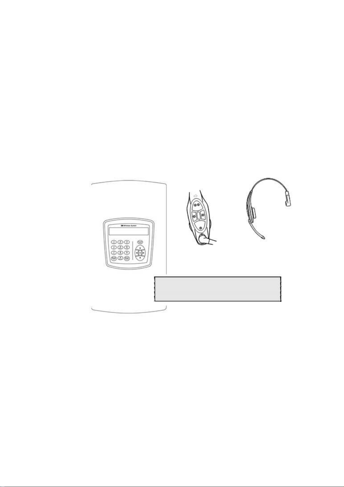
3M™ Wireless Communication System, Model XT-1
Operating Instructions
Rev 1.0
© 3M 2007 November
01>Drivethru Volume< 04 Registration
02>Monitor Volume< 05 Noise Reduction
03>Night Volume< 06 Set Time & Date
:SYSTEM MENU
Page 2

Table of Contents
Table of Contents
OVERVIEW ............................................................................................................................................ . 7
Safety Information ............................................................................................................................... 7
Safety Rules .................................................................................................................................... 7
Intended Use ................................................................................................................................... 7
Signal Words ................................................................................................................................... 7
Product Safety Labels ................................................................................................................... . 7
System Warnings ........................................................................................................................... 8
Other Conventions .............................................................................................................................. 8
Important Notes and Notes............................................................................................................. 8
FCC Information................................................................................................................................... 8
CONFIGURATION .................................................................................................................................. 9
Enter Configuration Mode.................................................................................................................... 9
Navigating the Base Station Display .................................................................................................. 9
Interpreting Display Information ..................................................................................................... 9
Buttons........................................................................................................................................... 10
Connecting to the Ethernet Port ....................................................................................................... 11
Network Setup .............................................................................................................................. 11
Logging into the Base Station with a Computer .......................................................................... 11
Change Basic Volume Settings......................................................................................................... 12
Inbound Microphone Volume ....................................................................................................... 12
Outbound Talk Volume ................................................................................................................ 12
Vehicle Alert Volume .................................................................................................................... 12
Outbound Greeter Message Volume........................................................................................... 13
Change the Monitor Volume ............................................................................................................. 13
Inbound Listen .............................................................................................................................. 13
Outbound Talk .............................................................................................................................. 13
Vehicle Present ............................................................................................................................. 14
Vehicle Approach ......................................................................................................................... 14
Page Messages ............................................................................................................................ 14
Greeter Messages ........................................................................................................................ 14
Change the Night Volume ................................................................................................................ 15
Registering Headsets ........................................................................................................................ 15
Add Headsets ............................................................................................................................... 15
Remove Headsets ........................................................................................................................ 16
List All Headsets ........................................................................................................................... 16
Resetting Inactive Days ................................................................................................................ 16
Checking Headset Software Revision ......................................................................................... 16
Change Noise Reduction Level ........................................................................................................ 16
Inbound Microphone Noise Reduction Level............................................................................... 16
Acoustic Echo Canceller............................................................................................................... 17
Set System Date and Time... ............................................................................................................ 17
Change Global Settings .................................................................................................................... 17
Text and Audio Prompts Language ............................................................................................. 17
Drive Thru Audio Duplex Mode .................................................................................................... 18
Page Channel Heard by Order Taker.......................................................................................... 18
Number of Base Stations at this Site............................................................................................ 18
Store is Now Closed Prompt ........................................................................................................ 19
Pull Ahead Prompt......................................................................................................................... 19
Customer Order Point Prompt Language ................................................................................... 19
Order Point TALK with No Vehicle .............................................................................................. 19
Order Takers in Cross Lane Mode .............................................................................................. 19
3M™ Wireless Communication System, Model XT-1: Operating Instructions Rev 1.0 © 3M 2007 November
Page 3 of 48
Page 3

Table of Contents
Detector Type ................................................................................................................................ 20
Order Taking Modes Setup ............................................................................................................... 20
Change Site Scheduling..................................................................................................................... 20
Regular Site Schedule .................................................................................................................. 21
Holiday/Exception Schedule ......................................................................................................... 21
Change Site Information ................................................................................................................... 21
Change Self Monitoring ..................................................................................................................... 21
Change Passcodes ........................................................................................................................... 22
User Passcodes ............................................................................................................................ 22
Installer Setup .................................................................................................................................... 22
Load Installation Settings .............................................................................................................. 22
Save Installation Settings ............................................................................................................. 23
Factory Setup (Restore Factory Defaults)......................................................................................... 23
Create and Load Templates ............................................................................................................. 23
Reboot System................................................................................................................................... 23
Check the Revision Levels ................................................................................................................ 23
Activate the Backup Intercom ........................................................................................................... 24
OPERATION ... ...................................................................................................................................... 25
Headsets ............................................................................................................................................ 25
Overview ... .................................................................................................................................... 25
Component Identification and Description ................................................................................................ 25
Fitting the Headset ........................................................................................................................ 26
Replace the Battery ...................................................................................................................... 26
Out of Range ................................................................................................................................. 27
Cleaning......................................................................................................................................... 27
Base Station Setup ............................................................................................................................ 28
Navigating in the Base Station in Run Mode ............................................................................................ 28
Change Order Taking Mode ......................................................................................................... 28
Explanation of Order Taking Modes ......................................................................................................... 29
Listen: Auto, Manual, and Always On .................................................................................................. 29
Talk: Manual Latching, Push to Talk, Automatic ................................................................................. 29
Automatic Standby: On and Off ........................................................................................................... 30
Vehicle Detector: Presence or Ignored ................................................................................................ 30
Order Point: Used or Not Used ............................................................................................................ 30
Which Order Taking Mode to Select ........................................................................................................ 30
Change Lane Mode ...................................................................................................................... 30
Split Lane ................................................................................................................................................... 31
Cross Lane ................................................................................................................................................ 31
Change Volume Mode .................................................................................................................. 31
MAINTENANCE .................................................................................................................................... 33
Headset ............................................................................................................................................. . 33
Replacing the Ear and Headband Pads ...................................................................................... 33
Battery Charger.................................................................................................................................. 33
Location ......................................................................................................................................... 33
Cleaning the Contacts .................................................................................................................. 33
Batteries.............................................................................................................................................. 34
Care, Handling and Storage ......................................................................................................... 34
Low Battery Message ................................................................................................................... 34
Charging Batteries ........................................................................................................................ 34
Disposing of Batteries.................................................................................................................... 34
Making Sure Batteries are Ready for Use ................................................................................... 35
Important Information about XT-1 Rechargeable Batteries.......................................................... 35
3M™ Wireless Communication System, Model XT-1: Operating Instructions Rev 1.0 © 3M 2007 November
Page 4 of 48
Page 4

Table of Contents
TROUBLESHOOTING ......................................................................................................................... 37
General Troubleshooting .................................................................................................................. 37
Battery and Battery Charger Troubleshooting ................................................................................. 38
APPENDIX: BASE STATION SPECIFICATIONS .............................................................................. 39
Physical ............................................................................................................................................. 39
Electrical ............................................................................................................................................ 39
Functional........................................................................................................................................... 39
APPENDIX: GREETER MODULE ....................................................................................................... 41
Greeter Setup .................................................................................................................................... 41
Enter the Greeter Configuration Menu ........................................................................................ 41
Play Greeter Message .................................................................................................................. 41
Select Specific Greeter Messages .............................................................................................. 41
Change Playback Mode ............................................................................................................... 41
Change Playback Delay Time ..................................................................................................... 42
Set Greeter Playback through Headsets ..................................................................................... 42
Set Playback through Monitor ...................................................................................................... 42
Turn on Tone to Headsets During Greeter Playback ................................................................. 43
Turn on Restaurant Closed Playback Message ......................................................................... 43
Turn on External Detector Playback Message ........................................................................... 43
APPENDIX: FCC and Safety Statement ... .......................................................................................... 44
Greeter Setup .................................................................................................................................... 41
Enter the Greeter Configuration Menu ........................................................................................ 41
Play Greeter Message .................................................................................................................. 41
Select Specific Greeter Messages .............................................................................................. 41
Change Playback Mode ............................................................................................................... 41
Change Playback Delay Time ..................................................................................................... 42
Set Greeter Playback through Headsets ..................................................................................... 42
Set Playback through Monitor ...................................................................................................... 42
Turn on Tone to Headsets During Greeter Playback ................................................................. 43
Turn on Restaurant Closed Playback Message ......................................................................... 43
Turn on External Detector Playback Message ........................................................................... 43
INDEX .................................................................................................................................................... 45
3M™ Wireless Communication System, Model XT-1: Operating Instructions Rev 1.0 © 3M 2007 November
Page 5 of 48
Page 5

Table of Contents
3M™ Wireless Communication System, Model XT-1: Operating Instructions Rev 1.0 © 3M 2007 November
Page 6 of 48
Page 6
Safety Information
Safety Rules
Intended Use
Overview
Overview
Read, understand, and follow all safety information contained in these
instructions prior to installation & operation of the 3M Headset Intercom
System, Model XT-1. Failure to follow all instructions listed could result in
electrical shock, fire and/or other personal injury. Retain these instructions for
future reference.
The 3M Headset Intercom System Model XT-1 is intended for use to provide 2way radio-frequency audio communication in quick service drive-through
restaurants and convenience stores.
The system must be installed as specified in the Model XT-1 Installation
Instructions and operated as specified in Model XT-1 Operating Instructions in
quick service drive-through restaurants and convenience stores. It has not been
evaluated for other uses or locations.
Signal Words
WARNING:
CAUTION:
CAUTION:
Explanation of Signal Word Consequences
Indicates a potentially hazardous situation, which, if
not avoided, could result in death or serious injury
and/or property damage.
Indicates a potentially hazardous situation, which, if not
avoided, may result in minor or moderate injury and/or
property damage.
Indicates a potentially hazardous situation, which, if not
avoided, may result in property damage.
Product Safety Labels
Explanation of Product Safety Labels
Attention: Read accompanying documentation
3M™ Wireless Communication System, Model XT-1: Operating Instructions Rev 1.0 © 3M 2007 November
Warning: Risk of Electric Shock
Page 7 of 48
Page 7
Overview
System Warnings
To reduce the risks associated with hazardous voltage:
•
Disconnect power to the receptacle before installing or removing the
Base Station Power Supply. When removing receptacle cover screw,
cover may fall across plug pins or receptacle may become displaced. Use
only with duplex receptacle having center screw. Secure unit in place by
receptacle cover screw.
•
If power supply is supplied with a grounding pin, connect directly to a
To reduce the risks associated fire & property damage:
grounding receptacle - 3 prong.
•
Do not open, crush, expose to heat above 200 °F or incinerate the
battery.
•
Always replace batteries, battery chargers and power supplies with
3M approved units acceptable for use in this system to avoid system
function & safety concerns.
WARNING
CAUTION
To reduce the risks associated with environmental contamination due to battery
pack & to lead in the solder:
•
Dispose of batteries, power supplies, battery charger and base
station in accordance with federal, state & local requirements. If
preferred, return these components to 3M Service Center for
disposal.
Other Conventions
Important Notes and Notes
Important Note:
It is strongly recommended that you pay attention to information inside of an
“Important Note:” box.
Note:
You may find information inside of a “Note:” box helpful.
FCC Information
Note:
This equipment has been tested and found to comply with the limits for a
Class A digital device, pursuant to part 15 of the FCC Rules. These limits are
designed to provide reasonable protection against harmful interference when
the equipment is operated in a commercial environment. This equipment
generates, uses, and can radiate radio frequency energy and, if not installed
and used in accordance with the instruction manual, may cause harmful
interference to radio communications. Operation of this equipment in a
residential area is likely to cause harmful interference in which case the user
will be required to correct the interference at his own expense.
3M™ Wireless Communication System, Model XT-1: Operating Instructions Rev 1.0 © 3M 2007 November
Page 8 of 48
Page 8

Configuration
Configuration
Enter Configuration Mode
Configuration mode is a passcode-protected area that contains most of the
configuration options for the base station system. Using the access provided for
users it is possible to set up all of the functionality of the system.
To enter the configuration mode:
1. From the Run mode menu, press and hold
2. While continuing to hold
3. Release
(e.g.,
Mode
. The display will show the user name and ID number
User1 ID = 1
, enter your user passcode.
Mode
)
Notes:
The default user password is 1234.
There are two levels of passcode: installers and users. Using a user’s
passcode permits you into the entire system menu.
Navigating the Base Station Display
Once you are in the configuration mode, you can use the buttons on the base
station display to update all configuration parameters.
Interpreting Display Information
Depending upon what you are doing, or what you can do, text on the display
screen is handled according to the following conventions:
Static or Informational
<Editable, not selected>
>Editable, Selected<
Editable, in Edit Mode
[Variable, not Editable]
{ information }
3M™ Wireless Communication System, Model XT-1: Operating Instructions Rev 1.0 © 3M 2007 November
Editable items that are currently
Mode
.
Static, informational, or noneditable text has no markings on
it.
Editable items that are not
currently-selected appear inside
of outwardly-pointing pointers.
Editable items that are currentlyselected appear inside if
inwardly-pointing pointers.
being edited have arrows
pointing inwardly.
Variable items that cannot be
edited appear inside of square
brackets. In some cases the item
is editable, but only from a
different location in the menu.
An on-screen explanation of a
key point or reminder appears
within curved brackets.
Page 9 of 48
Page 9

Configuration
Buttons
Following is a brief description of the buttons on the display and their functions.
Directional arrow
(
⌃
) buttons
Number/letter (0 - 9)
buttons
Mode (Exit)
button
Enter (Select)
buttons (both
buttons perform the exact
same functions)
You can use these buttons to scroll around
when navigating the menus. When you are
editing information, the up and right arrows
scroll “up” (increment) and the down and left
arrows scroll “down” (decrement) list of
values.
You can use these buttons to specify exact
numbers or letters in fields that permit them.
Each time you press button, the result
changes to the next available number or
letter. For instance, pressing the 7 button
three times creates a letter “t” (7-s-t). See
Service
button below for creating upper-case
letters.
In run mode, you must press and hold
Mode
while entering your passcode to enter user or
installation service.
In user and installation service modes, use
the
Mode
button to exit from a current field
that you are editing without saving any
changes or to go upward (backward) in the
configuration menus.
Use the
Enter
button to execute the current
selection:
Pressing
Enter
on a menu opens the menu
and shows you its submenu items.
Pressing
Enter
on an editable field switches you
to edit mode so you can change the value in the
field using the arrows and
number/letter buttons where applicable.
Pressing
Enter
while in edit mode saves the
changes you have made and exits edit mode.
3M™ Wireless Communication System, Model XT-1: Operating Instructions Rev 1.0 © 3M 2007 November
Page 10 of 48
Page 10

Service (Shift)
button Use the
letters or to initiate a service call to 3M or as a
confirmation in some items.
Pressing and holding the
editing a field that permits alphabet letter
entry (e.g., store address) shifts the letter to
upper case.
In run mode, press and hold the
button, then enter your passcode to initiate an
internet request for help from 3M. A 3M
representative will call your store telephone
number shortly after you initiate the request.
Your base station must be connected to the
internet for this function to work. If you
press the
passcode, the base station will go to a
Service screen used for installation and
troubleshooting.
Service
button to access upper-case
Service
Service
button and do not enter a
Configuration
button while
Service
The directional arrows can be used for scrolling from one menu item to another or
to scroll through available choices when editing fields.
Connecting to the Ethernet Port
All of the procedures in this chapter assume that you are using the display to
configure your base station(s). However it is also possible to configure the base
station using a desktop or laptop computer. To do so, use the display to set the
DSP configuration (see below), then connect the computer and the base station
using a patch cable (to a router) or a crossover cable (directly to a computer).
Network Setup
To configure the network:
• Enter the configuration mode (see above).
• Select
• Change the values for,
address, subnet mask, default gateway
Address Suffix
supply the values if you do not know them.
Logging into the Base Station with a Computer
Once the base station is connected to (and correctly configured with) your Local
Area Network, you can log into it from any other computer on the network and
operate the station as you would from the local interface. You must know the IP
Address of the base station and you must have password for one of the user
accounts in the base station
16 Network Setup
web server enabled, email enabled, IP
. Your network administrator should be able to
.
, and
Your E-Mail
To find out the base station’s IP address:
1. Enter the configuration mode (see above).
2. Select
16 Network Setup
3. Look at the series of numbers and decimals after
.
IP Address
.
(e.g., 133.75.123.27).
3M™ Wireless Communication System, Model XT-1: Operating Instructions Rev 1.0 © 3M 2007 November
Page 11 of 48
Page 11

Configuration
To find out your user password:
1. Enter the configuration mode (see page 9).
2. Select
3. Look at the passcode following your user number (e.g., “User 5.”)
To log into the base station:
• Using a web browser, type in the IP address of the base station in the
browser’s Address bar, then press
• Type in your user name and password. Do NOT type the space
between User and the user number (e.g., type “User5” instead of
“User 5”).
Notes:
The default user name is “User1”; the password is 1234.
Change Basic Volume Settings
Note:
All volume settings should be adjusted during normal or peak business hours.
Adjusting them during slow times will likely produce volume settings that are
too low.
Note:
Inbound and outbound are always defined from the perspective of the headset.
Inbound Microphone Volume
Changing the inbound microphone volume affects the sound volume coming
from the customer order point microphone.
To turn up or down the inbound microphone:
1. Enter the configuration mode, see page 9.
2. Select a new value for
Volume
Outbound Talk Volume
Changing the outbound talk volume affects the volume of the speaker at the
customer order point.
Note:
To avoid feedback, set the outbound talk volume as low as possible.
To change the outbound talk volume:
13 Change Passcodes
01 Drivethru Volume
>
Change User Passcodes
Enter
.
. The range is 0 (silent) to 20 (maximum).
>
Inbound Mic
.
1. Enter the configuration mode, see page 9.
2. Select a new value for
Volume
. The range is 0 (silent) to 20 (maximum).
01 Drivethru Volume
>
Outbound Talk
Vehicle Alert Volume
Changing the vehicle alert volume affects the volume of the vehicle alert signal
on the headsets.
3M™ Wireless Communication System, Model XT-1: Operating Instructions Rev 1.0 © 3M 2007 November
Page 12 of 48
Page 12

To change the vehicle alert volume:
1. Enter the configuration mode, see page 9.
2. Select a new value for
Volume
Outbound Greeter Message Volume
Changing the outbound greeter message volume affects the sound volume of the
custom greeting messages and the system internal greetings (“Store Closed” and
“Please Pull Ahead”).
To turn up or down the greeter message volume:
1. Enter the configuration mode, see page 9.
2. Select a new value for
Volume
Change the Monitor Volume
The monitor is an additional speaker that can be used to monitor drive thru
communication without a headset, typically in the kitchen. If the monitor has a
volume control built into it, you can use it to control the overall volume level of the
speaker. To be more specific about which elements you want to control, follow the
instructions in the following sections.
01 Drivethru Volume
. The range is 0 (silent) to 20 (maximum).
01 Drivethru Volume
. The range is 0 (silent) to 20 (maximum).
Configuration
>
Vehicle Alert
>
Greeter Message
Inbound Listen
Changing the inbound listen volume affects how loudly the monitor plays the
inbound (customer order point) communication. You can also disable the
monitor playing inbound sounds.
To change the inbound listen monitoring settings:
1. Enter the configuration mode, see page 9.
2. Select
02 Monitor Volume
.
3. To enable or disable the monitor playing the inbound sounds, change
the value for
4. To change the volume level, select a new value for
Volume
Inbound Listen: Enable
to ON or
. The range is 0 (silent) to 20 (maximum).
OFF
.
Inbound Listen:
Outbound Talk
Changing the outbound talk volume affects how loudly the monitor plays the
outbound (order taker) communication. You can also disable the monitor
playing outbound talk.
Note:
To avoid feedback and echo, set the outbound talk volume as low as possible.
To change the outbound talk monitoring settings:
1. Enter the configuration mode, see page 9.
2. Select
02 Monitor Volume
.
3. To enable or disable the monitor playing the outbound talk, change the
value for
4. To change the volume level, select a new value for
Volume
Outbound Talk: Enable
to ON or
OFF
. The range is 0 (silent) to 20 (maximum).
.
Outbound Talk:
3M™ Wireless Communication System, Model XT-1: Operating Instructions Rev 1.0 © 3M 2007 November
Page 13 of 48
Page 13

Configuration
Vehicle Present
Changing the vehicle present volume affects how loudly the monitor plays the
vehicle present tone. You can also disable the monitor playing the vehicle
present tone.
To change the vehicle present monitoring settings:
1. Enter the configuration mode, see page 9.
2. Select
3. To enable or disable the monitor playing the vehicle present tone,
change the value for
4. To change the volume level, select a new value for
Present: Volume
Vehicle Approach
Some sites are equipped with a vehicle approach detector, which alerts you
when a vehicle enters the parking lot or drive through approach lane. If your
site is equipped with the detector, you can change the volume at which the tone
is played on the monitor. Also, if you do not wish to hear the tone, you can
disable it.
02 Monitor Volume
Vehicle Present: Enable
. The range is 0 (silent) to 20 (maximum).
.
to ON or
Vehicle
OFF
.
To change the vehicle approach monitoring settings:
1. Enter the configuration mode, see page 9. 2.
Select 02 Monitor Volume
.
3. To enable or disable the monitor from playing the vehicle approach
tone, change the value for
OFF
.
4. To change the volume level, select a new value for
Approach: Volume
Vehicle Approach: Enable
to ON or
Vehicle
. The range is 0 (silent) to 20 (maximum).
Page Messages
Paging is headset-to-headset communications. Changing the page message
volume affects how loudly the monitor plays internal paging messages. You can
also disable the monitor playing internal paging messages.
Note:
To avoid feedback and echo, set the volume as low as possible.
To change the page message volume monitoring settings:
1. Enter the user service mode, see page 9. 2.
Select 02 Monitor Volume
.
3. To enable or disable the monitor playing internal paging messages,
change the value for
4. To change the volume level, select a new value for
Volume
. The range is 0 (silent) to 20 (maximum).
PAGE Messages: Enable
to ON or
OFF
.
PAGE Messages:
Greeter Messages
Changing the greeter message volume affects how loudly the monitor plays the
greeter messages. You can also disable the monitor playing the greeter
messages.
To change the greeter message volume monitoring settings:
1. Enter the configuration mode, see page 9.
3M™ Wireless Communication System, Model XT-1: Operating Instructions Rev 1.0 © 3M 2007 November
Page 14 of 48
Page 14

2. Select
3. To enable or disable the monitor playing greeter messages, change the
value for
4. To change the volume level, select a new value for
Change the Night Volume
You can assign a standard reduction in the volume level of the customer order point
speaker for night hours when lower volume is typically required. With the night
volume set, the system automatically adjusts the volume during night
hours, then back to normal during the day.
To change the night volume setting:
1. Enter the configuration mode, see page 9.
2. Select a new value for
Notes:
Night Volume is never higher than Day Volume.
Night volume reduction is a subtracted value, not the resulting level;
therefore, if it is the same as the day volume level, the speaker will turn off at
night.
02 Monitor Volume
Greeter Messages: Enable
Messages: Volume
Volume At Night By
. The range is 0 (silent) to 20 (maximum).
level.
Configuration
.
to ON or
03 Night Volume
. The range is 0 to the current day volume
OFF
.
Greeter
>
Reduce DriveThru
You cannot change the day outbound talk volume on this screen, only the
reduction amount identified above.
Registering Headsets
Each headset must be registered to a base station before it can be used. Once
registered, it should not need to be registered again unless it is intentionally
removed.
Add Headsets
Each headset has a unique identification number. The number is imprinted on the
headset and broadcast to the base station whenever it is turned on.
Notes:
One headset should not be registered to more than one base station at any
given site, whether or not the bases are interconnected. Remove the headset
from the existing base station before adding it to a different one.
To register a headset:
1. Enter the base station configuration mode, see page 9.
2. Select
3. Power on the headset when prompted.
4. Wait up to two minutes for
5. Repeat step 3 for additional headsets.
6. Press
04 Registration
Registered!}
when finished.
Mode
>
1 Add New Headsets
{Headset xxxxxxx Has Been
to appear at the bottom of the display.
.
3M™ Wireless Communication System, Model XT-1: Operating Instructions Rev 1.0 © 3M 2007 November
Page 15 of 48
Page 15

Configuration
Remove Headsets
Perform the following steps to un-register a lost, destroyed, or otherwise
removed headset from the system, including a headset that is sent back to 3M
for repair. The headset would have to be registered again at a later date.
1. Enter the base station configuration mode, see page 9.
2. Select
3. Scroll to the number of the headset you want to un-register.
4. Press
Enter
Note:
If you do not know or have access to the number of the headset to be
unregistered, identify the headsets that you want to remain in service and
unregister any that remain on the list.
List All Headsets
To see a list of the registered headsets:
1. Enter the base station configuration mode, see page 9.
2. Select
Resetting Inactive Days
For any headset, you can manually reset its number of inactive days to zero (see
“Change Self Monitoring” on page 21 for information about the inactive days
timer.
04 Registration
.
04 Registration
>
2 Remove Headsets
>
3 List All Headsets
.
.
To reset the inactive days:
1. Enter the base station configuration mode, see page 9.
2. Navigate to
08 Headset Setup
>
Currently Editing Headset
.
3. Press or if necessary to scroll to the headset ID number for the
headset you want to reset.
4. Select
<CLEAR>
.
Checking Headset Software Revision
To check the software revision number for a headset:
1. Enter the base station configuration mode, see page 9.
2. Navigate to
08 Headset Setup
>
Currently Editing Headset
.
3. Press or if necessary to scroll through the headsets. The software
version appears next to the headset ID number.
Change Noise Reduction Level
There are several ways to improve the sound quality at the headset using the
following settings.
Inbound Microphone Noise Reduction Level
The inbound microphone noise reduction level setting reduces background noise to
make it easier to hear speech at the customer order point.
Perform the following steps to increase or decrease the noise reduction level.
1. Enter the base station configuration mode, see page 9.
3M™ Wireless Communication System, Model XT-1: Operating Instructions Rev 1.0 © 3M 2007 November
Page 16 of 48
Page 16

2. Make a new selection for
Acoustic Echo Canceller
Perform the following procedure if there is a delayed repetition (echo) of the
outbound sound:
1. Enter the base station configuration mode, see page 9.
2. Make a new selection for
Set System Date and Time
Perform the following procedure to set the system time and date.
1. Enter the base station configuration mode, see page 9.
2. Change the date and time values for
field to the next and type new values over the existing data in the
formats shown in parentheses:
Configuration
05 Noise Reduction
Noise Reduction Level
Max
. You may need to experiment for a setting that works best for your
. Options are
Off, Min, Low, Med, Hi
ambient noise environment.
05 Noise Reduction > Acoustic Echo
Chancellor
. Options are
Min, Low, Med
, and
experiment for a setting that works best for your ambient noise
environment and staff.
06 Set Time & Date
Time
and
Date
fields as required. Use the arrows to scroll from one
•
= Hours (01 to 24, e.g., 6:00 pm is 18)
HH
•
MM
= Minutes (01 to 60)
•
= Seconds (01 to 60)
SS
•
= Month (Jan, Feb, Mar, Apr, May, Jun, Jul, Aug, Sep, Oct,
MMM
Nov, or Dec)
•
DD
= day (01 to 31)
•
Year
= Last two digits of the year (00 to 99, 20 is fixed and
cannot be changed)
>
Inbound Mic
Max
. You may need to
in the
, and
Change Global Settings
Global settings are an assortment of options that you must choose based upon the
basic configuration of your system.
Text and Audio Prompts Language
You can choose between English, Spanish, and French language for all text and
audio prompts, which is essentially all of the factory prerecorded information
coming from the base station and all of the printed text on the display.
Note:
Changing the text and audio prompt language will also change the language of the
headset messages.
Perform the following procedure to change the text and audio prompts:
1. Enter the base station configuration mode, see page 9.
2. Change the value for
Prompts Language
3M™ Wireless Communication System, Model XT-1: Operating Instructions Rev 1.0 © 3M 2007 November
07 Global Settings
to
English, Español
>
Text & Audio
., or
Francais
.
Page 17 of 48
Page 17

Configuration
Drive Thru Audio Duplex Mode
The system can function using half duplex or full duplex modes. Choosing
between the two modes is based upon the desired operation.
Note:
In half duplex installations, all latching order taking modes and hands free
mode are disabled.
Perform the following procedure to change the drive through audio mode:
1. Enter the base station configuration mode, see page 9.
2. Change the value for
Duplex Mode
• In
to
Full
half-duplex
systems, when the order taker is speaking, it is
impossible to hear any speech coming from the customer order
point.
• In
full-duplex
systems, the order taker can speak and hear speech
coming from the customer order point at the same time.
Page Channel Heard by Order Taker
You can enable or disable the order taker from being able to hear any paging
while speaking to a customer over the customer order point. This may prevent
interference with the order taking process.
07 Global Settings
or
Half
.
>
DriveThru Audio
Perform the following procedure to enable or disable the order taker hearing
pages while talking:
1. Enter the base station configuration mode, see page 9.
2.
Select 07 Global Settings
.
3. To enable or disable the monitor playing the outbound talk, change the
value for
PAGE Channel Heard by Order Taker:
to NO or
YES
.
Number of Base Stations at this Site
When there are two base stations used together (tandem, dual, or side-by-side
drive thrus) they must be configured to work together.
Perform the following procedure to enable the two stations to work together:
1. On the base first station:
• Enter the base station configuration mode, see page 9.
• Change the value for
BaseStations at This Site
• Press
to implement the change.
Enter
• On the first base station, stations, change the value for
Global Settings > Lane Number of This Base
Station
to 1.
07 Global Settings
to 2.
>
Number of
07
2. On the second base station:
• Enter the base station configuration mode, see page 9.
• Change the value for
BaseStations at This Site
• Press
Enter
to implement the change.
• On the second base station, stations, change the value for
Global Settings > Lane Number of This Base
Station
to 2.
07 Global Settings
to 2.
>
Number of
07
3M™ Wireless Communication System, Model XT-1: Operating Instructions Rev 1.0 © 3M 2007 November
Page 18 of 48
Page 18

Store is Now Closed Prompt
Perform the following procedure to enable or disable the automatic store closed
prompt to let customers know in your absence that the store is closed:
1. Enter the base station configuration mode, see page 9.
2. Change the value for
Closed” Prompt?
07 Global Settings
to
Yes
Pull Ahead Prompt
Perform the following procedure to enable or disable the automatic pull ahead
prompt to let customers know to pull ahead when they are at an out-of-service
customer order point in a tandem drive thru:
1. Enter the base station user service mode, see page 9.
2. Change the value for
Prompt (Tandem Only)?
07 Global Settings
Customer Order Point Prompt Language
Perform the following procedure to select the language(s) of the store closed and
pull ahead prompts. The prompts can be spoken in English, Spanish, French, or
repeated in multiple languages:
or No.
to
Yes
or No.
Configuration
>
”Store is Now
>
”Pull Ahead”
1. Enter the base station configuration mode, see page 9.
2. Change the value for
Prompts in English?
3. Press
Enter
to implement the change or press
change and leave the option at its previous setting.
4. Change the value for
Prompts in Spanish?
5. Press
Enter
to implement the change or press
change and leave the option at its previous setting.
6. Change the value for
Prompts in French?
Order Point TALK with No Vehicle
Perform the following procedure to permit or prevent the order taker to talk to
the order point when no vehicle is detected.
1. Enter the base station user service mode, see page 9.
2. Change the value for
With No Vehicle?
Order Takers in Cross Lane Mode
In systems with two customer order points, in
whether you would like to be able to permit communication between the two
split systems.
Perform the following procedure to enable or disable talk (T1/T2) buttons to be
able to speak on the lane to which it is not assigned.
07 Global Settings
to
Yes
or No.
07 Global Settings
to
Yes
or No.
07 Global Settings
to
Yes
or No.
07 Global Settings
to
Yes
or No.
Split Lane
>
Order Point
Mode
to abandon the
>
Order Point
Mode
to abandon the
>
Order Point
>
Order Point TALK
mode, you can specify
1. Enter the base station configuration mode, see page 9.
2. Change the value for
CROSS Lane Mode?
07 Global Settings
to
YES
or NO.
>
Order Takers in
Perform the following procedure to enable or disable paging to be heard by
operators on both lanes.
1. Enter the base station configuration mode, see page 9.
3M™ Wireless Communication System, Model XT-1: Operating Instructions Rev 1.0 © 3M 2007 November
Page 19 of 48
Page 19

Configuration
2. Change the value for
Cross Lanes?
Detector Type
Because there are two basic types of vehicle detector, pulse and presence, you
must specify which type you have in the base station.
1. Enter the base station configuration mode, see page 9.
2. Change the value for
Detector#1
Note:
Vechicle detector#1 is always the order point.
3. For presence type detectors, specify a value for
#X Minimum (Seconds)
customer’s wait time, but decrease false detections that could be caused by
cars driving over the detector without stopping.
Notes:
When the pulse setting is used, each call must be ended by pressing the page
button on the headset.
If you are using a vehicle detector board, the presence or pulse setting should
match the dip switch setting on the board.
If the vehicle detector is set to delay (via its own dip switches) and you set a
delay in the base station, the delays are additive: you could end up with a longer
than expected total delay.
Order Taking Modes Setup
Perform the following procedure to enable or disable some of the seven different
order taking modes from appearing on the Run Menu:
1. Enter the base station configuration mode, see page 9.
2. Navigate to
09 O.T. Modes Setup
3. Change the value for each of the following options to
•
Manual Listen/Push To Talk
•
Manual Listen/Manual Latching Talk
•
Auto Listen/Push To Talk
•
Auto Listen/Manual Latching Talk
• Hands Free
• Outside
• Always On (Bypass Vehicle Detector)
(Press or ⌃ to scroll up and down the list)
Note:
Order taking modes are described in the Operation section, see page 29.
Change Site Scheduling
The site schedule is the calendar of store open and closing times.
3M™ Wireless Communication System, Model XT-1: Operating Instructions Rev 1.0 © 3M 2007 November
Page 20 of 48
07 Global Settings
to
or NO.
YES
07 Global Settings > Vehicle
to
Presence
or
Pulse
.
. Setting a higher number will increase the
.
>
PAGE Messages Can
Vehicle Detector
Yes
or No:
Page 20

Note:
All timekeeping is done using a 24 hour clock (e.g., 6:00 p.m. appears as
18:00).
Regular Site Schedule
The regular site schedule is the opening and closing times for each day of the
week and the times assigned as “Day” and “Night,” which determine when the
day and night volume settings change.
Perform the following procedure to set the regular site schedule:
1. Enter the base station configuration mode, see page 9.
2. Navigate to
3. Change the value for each day of the week and each of the four defined
fields (
Open, Day, Night
(Press , ⌃, , and to scroll up and down the list).
Holiday/Exception Schedule
The holiday/exception schedule can be used to identify up to 12 days in the year on
which the store schedule is different than it would have been otherwise. The
holiday/exception schedule should be updated at least once a year to ensure it
conforms to the current year’s calendar.
10 Site Scheduling
, and
Close
>
Regular Site Schedule
).
Configuration
.
Perform the following procedure to set the holiday/exception schedule:
1. Enter the base station configuration mode, see page 9.
2. Navigate to
3. For each day that needs a non-typical schedule, enter the three-letter
month and two digit date under Date, then change the open and close
times on the line to the right of the date.
Change Site Information
Site information is useful for warranty registration and to support service calls.
This information is most useful when the system has an internet connection. Tech
Services can use it to identify and contact the store when it receives a service
request. All information is entered free-format using the numeric
keypad. To type upper case letters, use the Shift key.
Perform the following procedure to change the site information:
1. Enter the base station configuration mode, see page 9.
2. Navigate to
3. For each field that needs to be modified, enter the appropriate data.
(Press , ⌃, , and to scroll through the fields.)
Change Self Monitoring
Self-monitoring is a function available for all systems where the base station is
continuously connected to a store Ethernet connection. The base station keeps
track of all of the headsets in the system, looking for periods of extended nonuse
that may indicate a headset problem that needs attention.
Schedule
10 Site Scheduling
.
.>
Holiday/Exception
(Press , ⌃, , and to scroll through the fields.)
11 Site Information
.
Perform the following procedure to enable and configure self monitoring:
1. Enter the configuration mode, see page 9.
2. Select
12 Self Monitoring
.
3M™ Wireless Communication System, Model XT-1: Operating Instructions Rev 1.0 © 3M 2007 November
Page 21 of 48
Page 21

Configuration
Change Passcodes
User Passcodes
3. To enable or disable self monitoring, change the value for
Monitoring Enabled?
to
Yes
or No.
Self
4. If self monitoring is enabled:
• Select a value for
Number of Inactive Days Allowed
.
The range is 7 to 255. The number represents how many days of
inactivity must pass for any given headset before the system
interprets the absence as a problem and forwards the
information to 3M.
• Select a value for
are
Never, Every Day, Every Week
Resend Error Reports
, or
. Your choices
Every Month
.
This is the frequency that the base station will attempt to
resend the error message until the error condition is corrected.
User and installer passcodes can be individualized for better security control
against unauthorized changes. The system has a default user and a default
installer passcode pre-installed. Check your documentation for those passcodes.
If you enter a user passcode, you have full access to the Change User Passcodes
menu. You can change or delete any passcode.
Perform the following procedure to set up and/or change user passcodes:
1. Enter the configuration mode, see page 9.
2. Select
13 Change Passcodes
>
Change User Passcodes
.
3. Identify the user number you want to change, then press , ⌃, , and
as necessary to scroll to the desired passcode.
4. Enter a new four-digit passcode in place of the old passcode.
5. Press
to implement the change or press
Enter
to abandon the
Mode
change and leave the passcode at its previous setting.
Installer Setup
Installer setup is a special group of setup options typically only used by the
installer or in case of complete system restoration or backup.
Load Installation Settings
Installation settings are a complete set of configuration data that the installer can
save after the initial installation configuration is completed. It is essentially a
backup save point in case configuration settings are inadvertently changed in ways
that are not easy to identify or correct.
To load the installation settings:
Important Note:
By performing this procedure you will be erasing the current configuration and
reloading the configuration that was last saved, likely when the system was
first installed.
1. Enter the configuration mode, see page 9.
2. Select
3. Change the value for
3M™ Wireless Communication System, Model XT-1: Operating Instructions Rev 1.0 © 3M 2007 November
Page 22 of 48
14 Installer Setup
Load Installation Settings
.
to
Yes
.
Page 22

Save Installation Settings
Note:
This function is only available to installers.
Perform the following procedure to save the current configuration into
permanent memory over the existing installation settings.
Important Note:
By performing this procedure you will be erasing the existing saved
installation settings, making it impossible to revert to the settings that were
saved after installation.
1. Enter the configuration mode, see page 9.
2. Select
14 Installer Setup
3. Change the value for
Factory Setup (Restore Factory Defaults)
Perform the following procedure to restore all of the configuration settings to the
factory default settings. This procedure should be performed only if the current
configuration and the saved installation settings are unusable.
Important Note:
By performing this procedure you will reset the system to the initial
configuration, making it impossible to revert to the settings that were saved
after installation.
1. Enter the configuration mode, see page 9.
2. Select
3. Change the value of
15 Factory Setup
.
Save Installation Settings
to
.
Restore All Factory Settings
Configuration
Yes
.
to
Yes
.
Create and Load Templates
You can save an entire base station configuration as a file on a PC and use the file
as a template for other base stations. You must be using a PC to use
templates.
Reboot System
Perform the following procedure to cleanly power down, then power up without
unplugging the system:
1. Enter the configuration mode, see page 9.
2. Select
3. Change the value of
4. Press
16 Reboot System
Power Cycle Complete System
.
Service
.
to
Yes
.
Check the Revision Levels
Perform the following procedure to view the revision levels and serial numbers of
your base station:
1. Enter the configuration mode, see page 9.
2. Select
3M™ Wireless Communication System, Model XT-1: Operating Instructions Rev 1.0 © 3M 2007 November
17 Revision Levels
.
Page 23 of 48
Page 23

Configuration
Activate the Backup Intercom
Many systems include a wired backup intercom system that can be used if the
main wireless system cannot be used. If your system has a backup intercom
system, perform the following steps to activate it:
• Remove the base station cover.
• Press and latch the two switches named “BACKUP INTERCOM.”
3M™ Wireless Communication System, Model XT-1: Operating Instructions Rev 1.0 © 3M 2007 November
Page 24 of 48
Page 24
Headsets
Operation
Operation
Overview
This chapter provides instructions for using headsets with an XT-1 Intercom
System after the system has been installed, configured, and powered on.
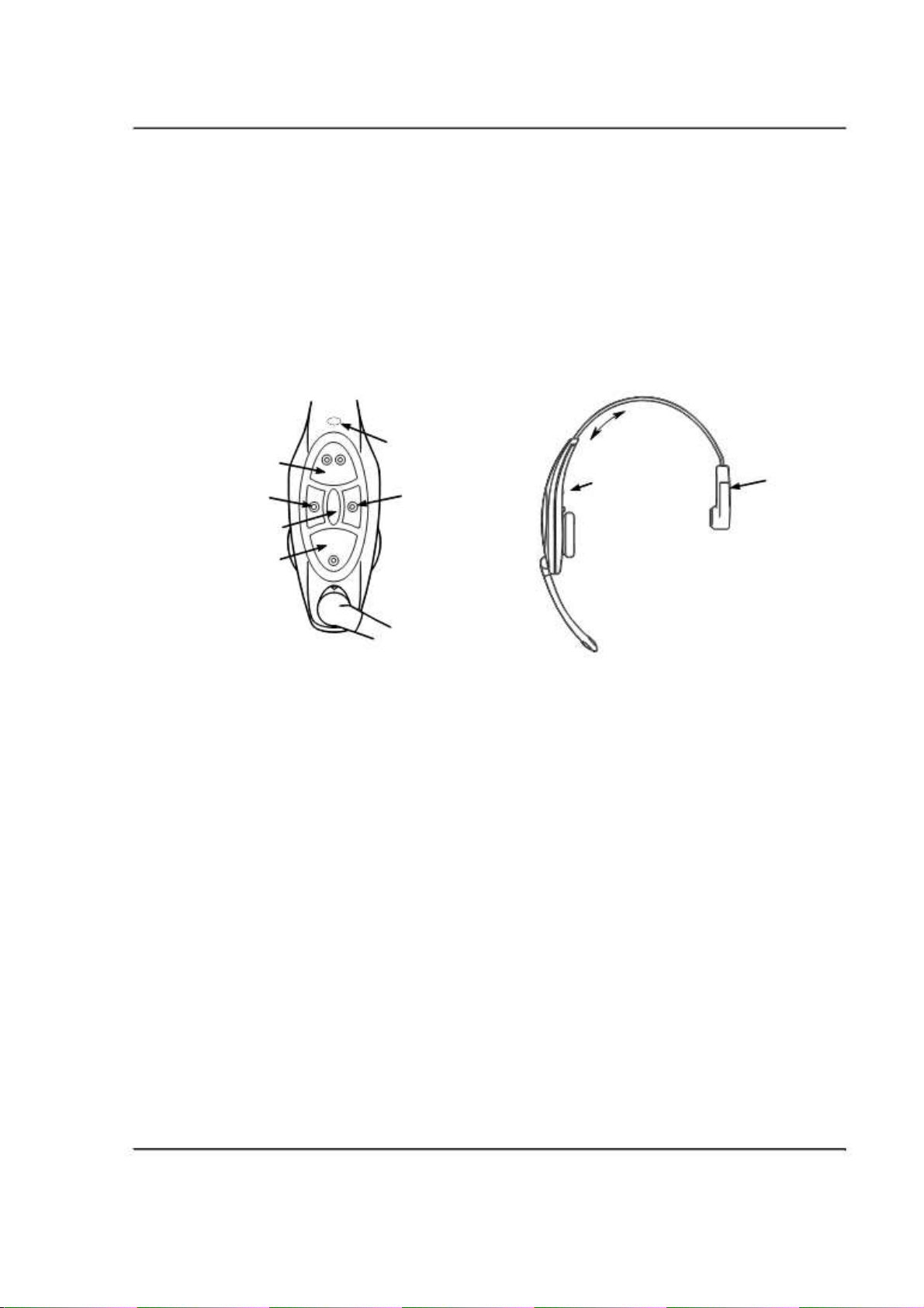
Component Identification and Description
Indicator LED
Volume Down Volume up
T2
Page
T1
•
Adjustment Slide
•
Indicator LED
: Push or pull to adjust for a comfortable fit.
: Indicates operating status of the headset.
Adjustment
Slide
On/Off Battery
Release
• Off (no light) indicates power is off. It will turn off
automatically if it fails to register within two minutes or if the
battery dies.
• Momentary amber flash indicates power was just turned on.
• Steadily flashing green indicates it is trying to register with the
base station.
• Momentary red flash indicates it has successfully registered with
a base station (“Lane 1” or “Lane 2” will also be heard in the
earpiece).
• Solid green indicates it is registered and is in standby mode.
• Solid red indicates it is the active order taker and will transmit
any sound it picks up to the order point.
• Steadily flashing red indicates it is the active order taker but the
microphone is muted.
•
T1 and T2
(Talk:buttons): Connect you to the order point.
• When there are two order points, T1 connects to order point 1
and T2 connects to order point 2.
• When there is only one order point, T1 and T2 both connect to
the order point.
• If you are in Manual Latching or Hands Free modes, the talk
button establishes you as the order taker; and while you are the
order taker, the talk button is an order point mute button (each
tap turns mute on or off to the order point).
3M™ Wireless Communication System, Model XT-1: Operating Instructions Rev 1.0 © 3M 2007 November
Page 25 of 48
Page 25
Operation
•
On/Off
•
Volume
volume.
•
Page
depending upon the configuration), but never to the order point. If the
order taker taps the page button, he or she is no longer the order taker.
The next person to press a talk button becomes the order taker. There
is an option in Global settings to allow the order taker to hear or not to
hear page messages.
•
Battery Release
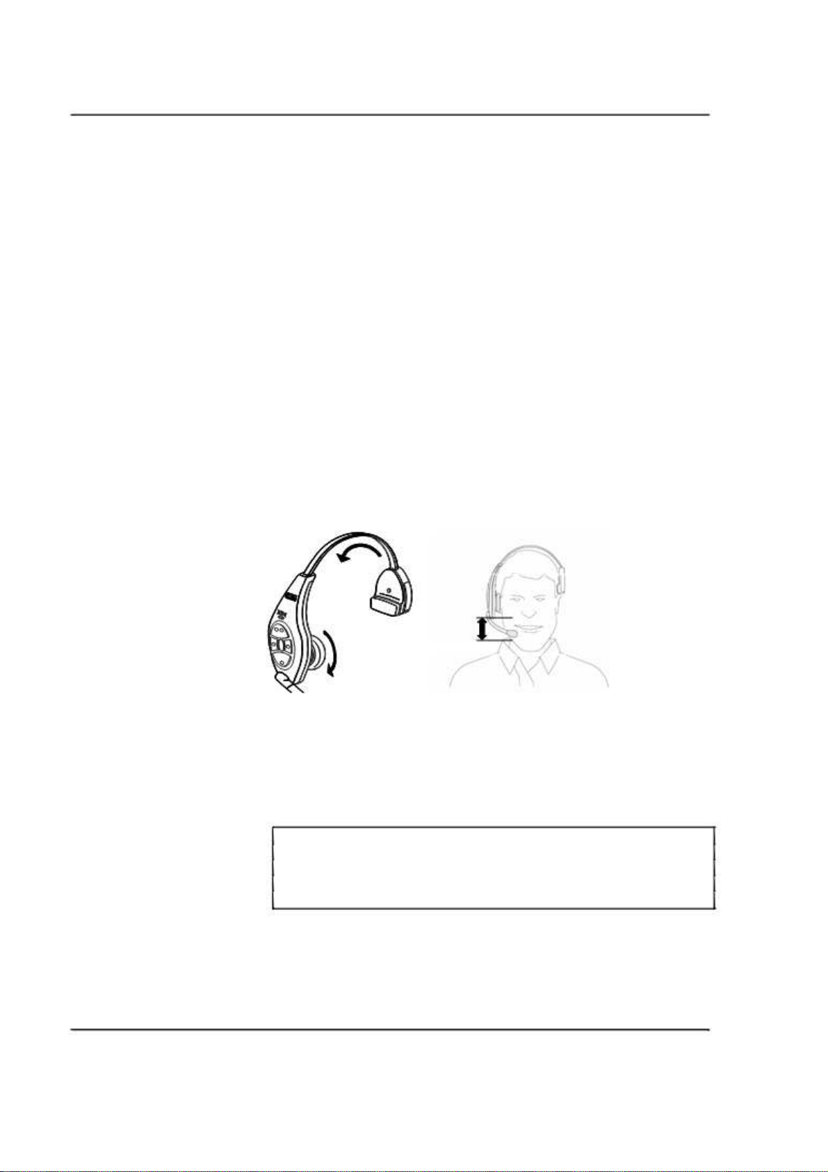
Fitting the Headset
Make the following adjustments to the headset to make it comfortable, less
likely to fall off, and easy for you to hear and speak clearly:
1. Rotate the ear cup and ear pad so that the indicator on the ear cup is
aligned to the back of your head.
2. Adjust the size of the headband until the ear pad rests against one ear
and the battery side pad rests just above the other ear.
3. Rotate the microphone boom up or down so its tip is in line with the
corner of your mouth. Do not bend the boom.
: Turns the headset on and off. Hold for 3 seconds to turn off.
: The up button increases volume, the down button decreases
: Allows you to talk to all headsets on the same lane (or both lanes
: Slide up to remove the battery.
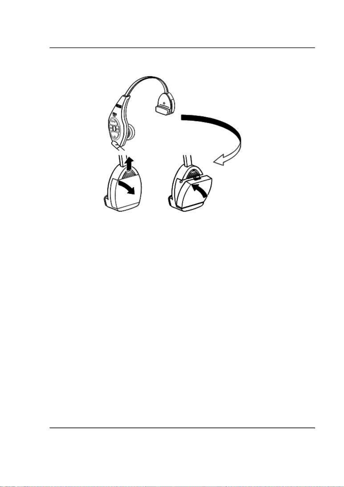
Replace the Battery
It is important to have fully charged batteries in the headset. When a battery is
low, the system plays a “change battery now” message in the headset every 15
seconds.
Note:
When installing a battery, make sure it is fully charged. It is important to
remember that an
week. If a battery has not been used for several weeks, make sure to charge it
prior to use.
1. Slide and hold the battery release.
2. Remove the discharged battery from the battery housing.
3. Insert a
battery release. Make sure the battery is fully inserted (battery release
clicks).
3M™ Wireless Communication System, Model XT-1: Operating Instructions Rev 1.0 © 3M 2007 November
Page 26 of 48
unused
fully charged battery
XT-1 battery loses five percent of its charge per
in the housing with the notch facing the
Page 26
Operation
Out of Range
In addition to “Change Battery Now” you may also hear a message for “Out of
Range.” If you hear this in your headset, you need to move closer to the Base
Station. You will know you are in range when you hear the message “Lane 1”
or “Lane 2.”
Cleaning
For good health and hygiene, you should clean the headsets regularly. Here are
some guidelines:
• Check the headsets every day. If they are dirty, clean them. Even if
they don’t look dirty, every headset should be cleaned on a regular
schedule.
• Before cleaning, remove the soft foam ear pad and microphone
windscreen. If used.
• Use a soft cloth and mild cleaning solution to wipe the surfaces clean.
We recommend using a 3M™ 504/7065 Cleaning Wipe or a 3M™
High Performance Cloth lightly dampened with 3M™ Food Service
Degreaser, 7L, (70-0708-3996-7).
• Remove stubborn particles from switches and clear plugged speaker
holes with a soft toothbrush.
• Gently clear plugged holes in the microphone tip with a wooden
toothpick.
• Do NOT soak the headset or immerse it in water; you might damage
the electronics.
• Do NOT bend the battery contact or microphone boom.
3M™ Wireless Communication System, Model XT-1: Operating Instructions Rev 1.0 © 3M 2007 November
Page 27 of 48
Page 27
Operation
Base Station Setup
Most of the base station configuration is performed during installation by the
installer or by a manager. The setup options listed in this section are only those
that can be performed without entering the passcode-protected areas of the base
station.
The following procedures are all performed at the base station using the base
station keypad. The base station must be turned on (plugged in) and in Run
Mode without a security passcode entered.
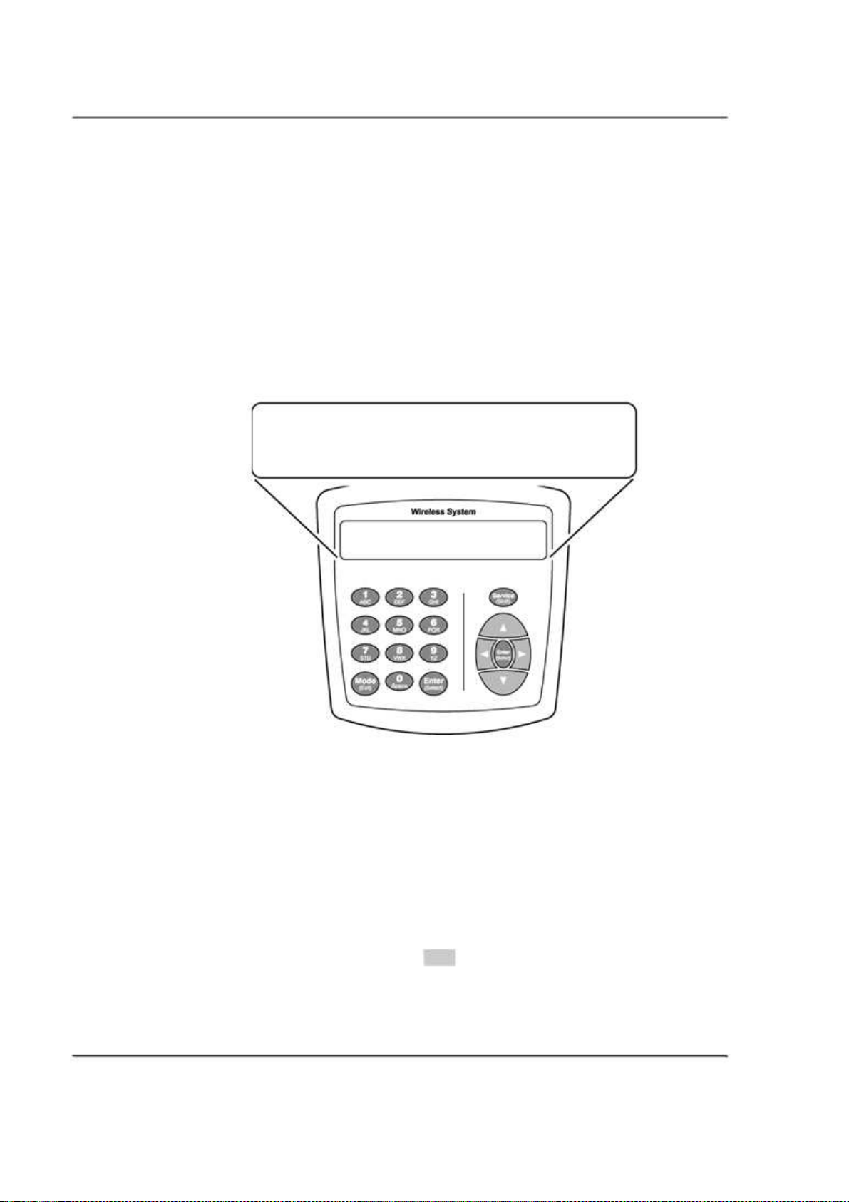
The following diagram shows how the display on the base station looks in Run
Mode.
13:25 WED,NOV/16/2005 | MODE< ML/PTT >
NOISE REDUCTION [LOW] | LANE 2 <SPLIT>
GREETER PLAYING MSG 1 | VOLUME < DAY >
Navigating in the Base Station in Run Mode
To navigate the base station in Run mode you only need to use
Enter, Mode
, and
the directional arrow buttons: up , down ⌃, left , and right . The
remaining buttons function only in manager or installer configuration modes.
Change Order Taking Mode
There are seven order taking modes, which offer different combinations of
speaking, listening, automatic standby, vehicle detector, and order point modes.
Perform the following procedure to switch to a different order taker mode:
1. Press ⌃ until the
2. Press
Enter
.
Mode
selection is highlighted.
3M™ Wireless Communication System, Model XT-1: Operating Instructions Rev 1.0 © 3M 2007 November
Page 28 of 48
Page 28
Operation
3. Press ⌃, , , or to select a new order taker mode. Your choices
are
ML/PTT, ML/MLT, AL/PTT, AL/MLT, Hands Free, Outside
Always On
Order Taking Mode to Select” below.
Note:
Your system may be configured with fewer order taking mode options than
the number described in this section. You must enter User configuration
(passcode required) to enable or disable individual order taking modes.
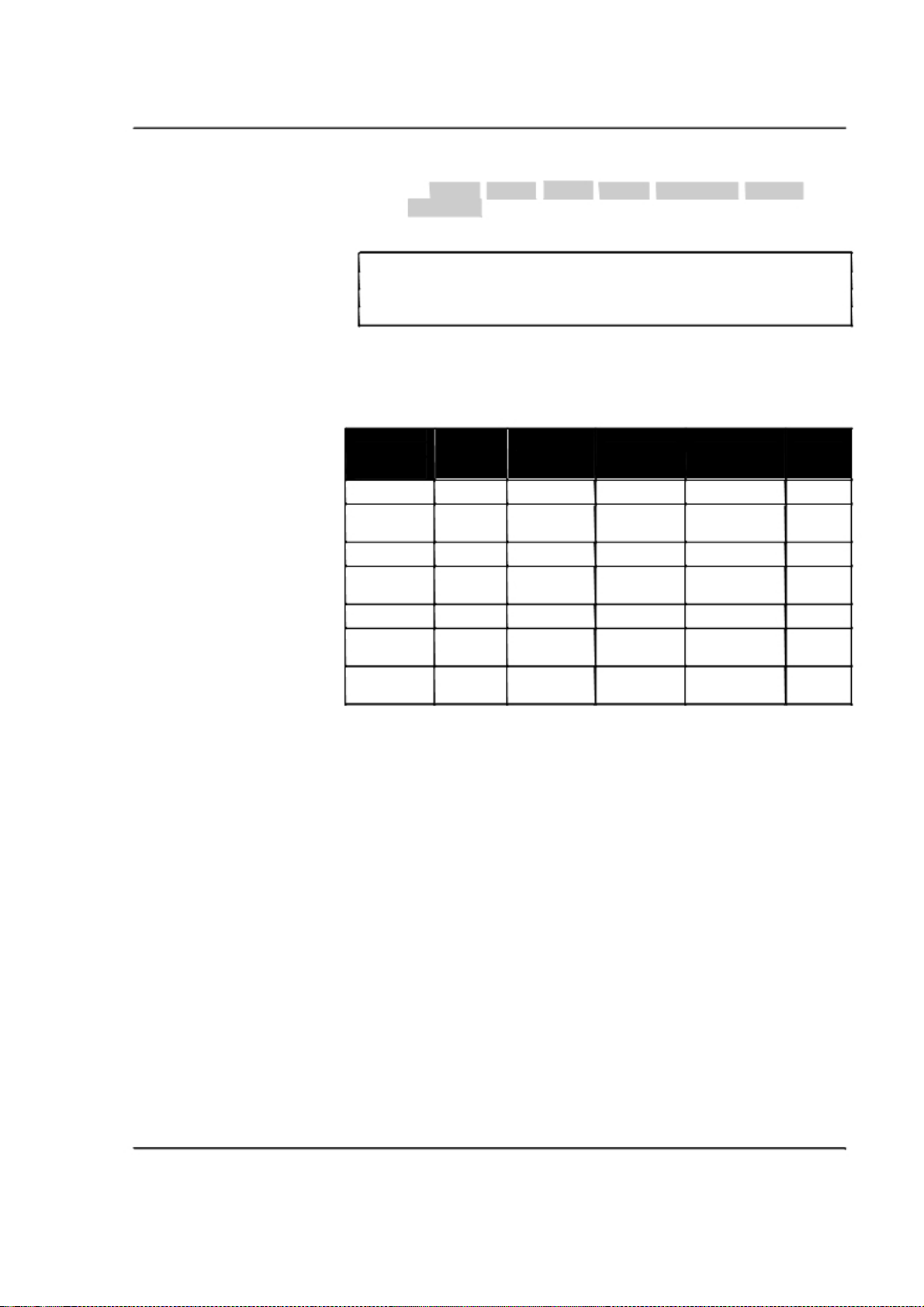
Explanation of Order Taking Modes
The following table shows how each order taking mode affects components and
settings in the system. The paragraphs that follow the table explain the meaning of
information in the table.
Order Listen Talk Vehicle Automatic Order
Taking Detector Standby Point
Mode
ML/PTT Manual Push to Talk Presence On Used
ML/MLT Manual Manual Presence On Used
AL/PTT Automatic Push to Talk Presence On Used
AL/MLT Automatic Manual Presence On Used
Hands Free Automatic Automatic Presence On Used
Outside Manual Manual Ignored Off Not
Always On Always on Manual Ignored Off Used
Listen: Auto, Manual, and Always On
In
Manual Listen
the order point microphone (to hear the customer order). The order point
microphone will remain on until the vehicle leaves.
In
Automatic Listen
whenever a vehicle is detected. The order point microphone will remain on until the
vehicle leaves.
. See “Explanation of Order Taking Modes,” and “Which
Latching
Latching
Latching Used
Latching
(ML), the operator must press the talk lane button to turn on
(AL), the order point microphone turns on and stays on
, and
In
Always On
be heard regardless of whether a vehicle is detected at the order point.
On
is a special failure mode that is useful if the vehicle detector cannot be used.
, the order point speaker is always on so the customer can always
Always
Talk: Manual Latching, Push to Talk, Automatic
In
Manual Latching Talk
(MLT), the operator must press and release the talk lane
button to “latch” or lock the headset microphone in the on position. The operator
can continue to speak hands free until the talk button is pressed and released again.
When
Automatic Standby
is on (see below), the microphone will also be turned off
when the vehicle is no longer detected.
In
Push to Talk
(PTT), the operator must press and hold the talk button while
speaking into the headset microphone. Releasing the button turns off the
microphone.
3M™ Wireless Communication System, Model XT-1: Operating Instructions Rev 1.0 © 3M 2007 November
Page 29 of 48
Page 29

Operation
In
Hands Free
detector detects a vehicle. Because
when
Hands Free
, the headset microphone is on whenever the order point vehicle
Automatic Standby
(see below) is also on
is On, the microphone is turned off when the vehicle is no
longer detected.
Automatic Standby: On and Off
When Automatic Standby is on, the order taker’s microphone and the order
point microphone turn off when the vehicle is no longer detected.
Vehicle Detector: Presence or Ignored
When the vehicle detector is on (in presence mode), a car entering the order
point is sensed and the ordering system reacts according to the order taking
mode. When the vehicle detector is off (ignored), Automatic Listen, Automatic
Talk, and Automatic Standby are unavailable. Only
Outside
or
Always On
order
taking modes are recommended when the vehicle detector cannot be used.
Order Point: Used or Not Used
When the order point is used, customers can order using any of the typical order
taking modes, with the exception of the Outside mode (see below for
explanation).
Which Order Taking Mode to Select
Each order taking mode is designed for a specific purpose so you do not need to
manually select the modes for the individual components and potentially end up
with a non-working configuration.
ML/PTT, ML/MLT, AL/PTT, AL/MLT
, and
Hands free
should be selected for
typical ordering configurations where all of the drive thru employees are inside
of the building and all of the equipment is working properly. The choices
between them tend to vary according to the number of people available, how
many duties they must perform simultaneously, and possibly employee
preferences.
If you plan to have the order taker standing outside with a headset,
Outside
mode is the best choice. The order point speaker, microphone, and vehicle
detector are disabled. This allows hands free communication to staff inside the
store for order entry and/or special requests.
If the vehicle detector is not functioning properly,
Always On
mode is the best
choice. The microphone at the order point is on continuously, regardless of the
status of the vehicle detector. Typically, when a vehicle detector fails, it reports
the presence of a vehicle continuously, which functions as (bookmark).
Change Lane Mode
Perform the following procedure to select the lane mode that is appropriate for
your current situation. Descriptions for the two modes follow the procedure.
4. Press ⌃ until the
Lane X
selection is highlighted (where X is the lane
number, 1 or 2).
5. Press
6. Press ⌃ or to select between the two possible lane modes:
and
7. Press
.
Enter
SPLIT
.
Enter
to implement the change or press
Mode
to abandon the
CROSS
change and leave the previous lane mode in effect.
3M™ Wireless Communication System, Model XT-1: Operating Instructions Rev 1.0 © 3M 2007 November
Page 30 of 48
Page 30

Split Lane
Split Lane
mode is the preferred mode for heavy volume because it essentially
separates the communications between the two base stations.
• Operators will only hear a signal from the order point last used: single
repeating beep from order point 1 or a double repeating beep from
order point 2.
• The headset buttons T1 and T2 communicate only with order point 1
and order point 2, respectively.
• For paging, pressing the page button on a lane 1 headset is only heard
by other lane 1 headsets. Likewise pressing the page button on a lane 2
headset is only heard by other lane 2 headset.
Notes:
A headset becomes a “lane 1” or “lane 2” headset by momentarily pressing
and releasing the T1 or T2 button.
You can configure the base stations to permit paging to be heard by both
lanes. Refer to configuration section of the manager’s guide.
Cross Lane
Cross Lane
mode is the preferred mode for lighter volume or whenever one
order taker needs to answer both order points: essentially, the two order points
cross over.
Operation
• Operators will hear signals from both order points: single repeating
beep from order point 1 or a double repeating beep beep from order
point 2.
• The headset buttons T1 and T2 communicate only with order point 1
and order point 2, respectively.
• For paging, pressing the page button is heard by all headsets.
Change Volume Mode
If you have night volume reduction in use on your system, the volume change
happens automatically at the set “Day” and “Night” times. However, you can
change the volume mode manually without changing the day or night time
setting.
Perform the following procedure to change between night and day or day and
night volume:
1. Press ⌃ until the
2. Press
Enter
3. Use the arrows to select between
4. Press
Enter
Volume
selection is highlighted.
.
DAY
and
to implement the change or press
NIGHT
Mode
.
to abandon the
change and leave the previous setting in effect.
3M™ Wireless Communication System, Model XT-1: Operating Instructions Rev 1.0 © 3M 2007 November
Page 31 of 48
Page 31

Operation
3M™ Wireless Communication System, Model XT-1: Operating Instructions Rev 1.0 © 3M 2007 November
Page 32 of 48
Page 32
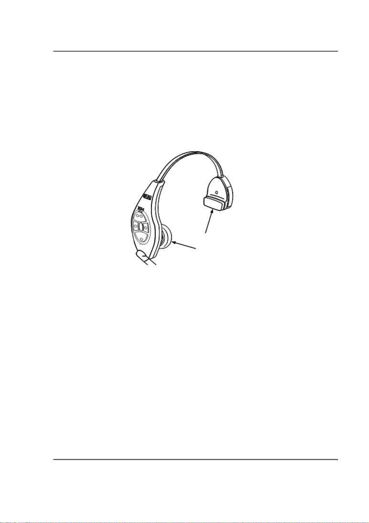
Headset
Maintenance
Maintenance
Replacing the Ear and Headband Pads
To replace the ear pad, remove the worn/damaged ear pad from the ear cup and
replace it with a new pad.
Headband Pad
Ear Pad
To replace the headband pad, remove the worn/damaged pad by peeling it from the
back of the battery housing. Remove protective backing from new pad and press it
into place on the back of the battery housing.
Battery Charger
Location
The battery charger should be placed on a flat surface such as a desktop or table in a
clean, dry environment.
Cleaning the Contacts
If the indicators fail to light during charger operation, clean the contacts using a
water-moistened cotton swab.
3M™ Wireless Communication System, Model XT-1: Operating Instructions Rev 1.0 © 3M 2007 November
Page 33 of 48
Page 33
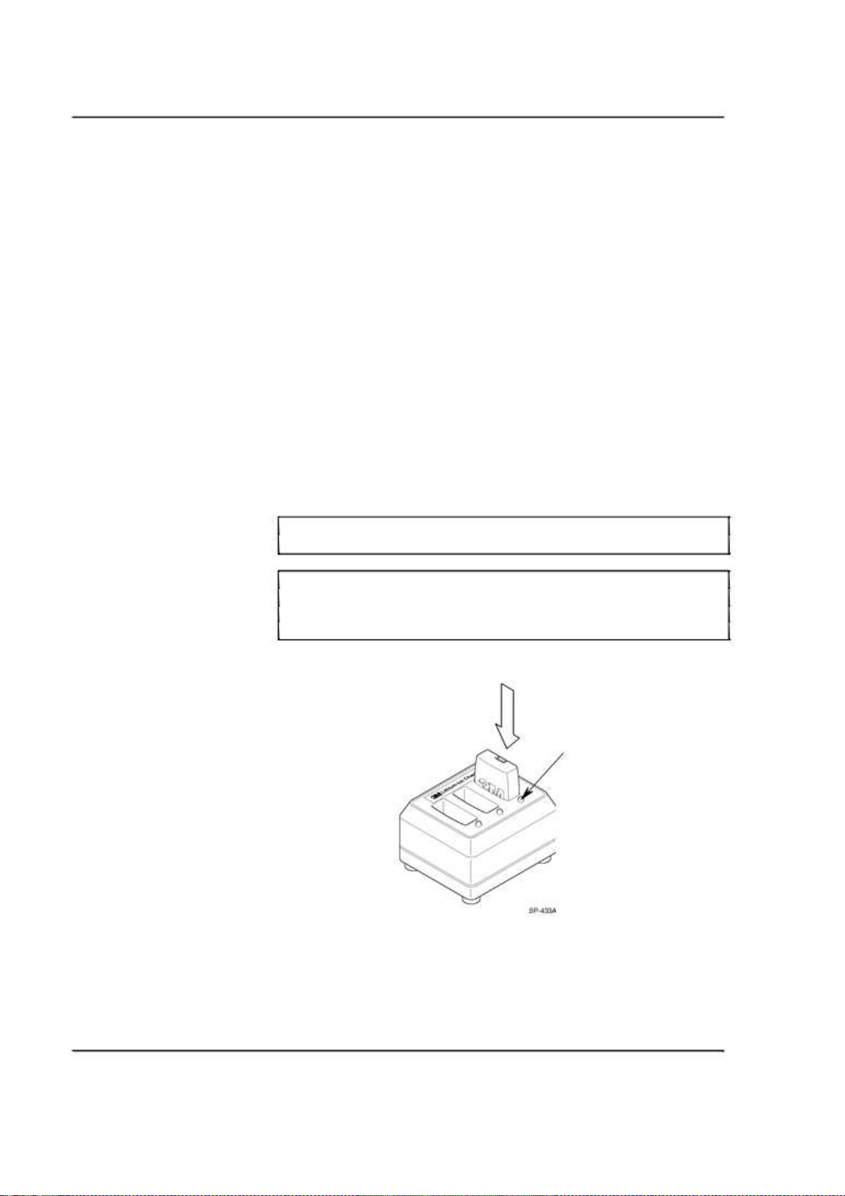
Maintenance
Batteries
Care, Handling and Storage
• Avoid dropping batteries.
• Do not carry batteries in your pockets or leave them in hot, damp or
dirty places.
• Clean the battery contacts periodically using a water-moistened swab.
• Be careful not to short the battery contacts together.
• Do not set the batteries contact-side down on a bare metal countertop.
Low Battery Message
When the battery voltage is too low, the headset sounds a “change battery now”
message at fifteen-second intervals to alert the operator to install a fully charged
battery. The “change battery now” message continues for two minutes after
which the headset turns off automatically to prevent damage to the batteries.
Charging Batteries
To charge a battery, insert the battery in one of the charging slots.
• The indicator lights RED to indicate the battery is charging.
• The indicator lights GREEN to indicate the battery is charged.
Note:
Discharged
batteries
Note:
When the GREEN
charged. An additional 1/2 hour of charging is required to achieve maximum
charge.
Disposing of Batteries
To help protect the environment and conform to regulations, XT-1 rechargeable
batteries must be returned to 3M at the end of their useful life. Contact your 3M
representative for additional instructions.
3M™ Wireless Communication System, Model XT-1: Operating Instructions Rev 1.0 © 3M 2007 November
Page 34 of 48
require 3 ½ hours to charge.
indicator
lights, the battery is approximately 80%
Charging
Status
Indicator
Page 34
Making Sure Batteries are Ready for Use
Follow these tips to make sure batteries are always ready for use:
• Have an extra battery for each headset. This helps ensure that a fully
charged battery is always available.
• Recharge a low battery as soon as it is removed from the headset.
When a battery is low, repeat messages are heard in the headset for 2
minutes, and then the headset shuts off.
• Keep the battery and charger contacts clean. Use a cotton swab and
approved cleaner in accordance with manufacturer’s instructions to
clean the contact surfaces.
• Remember that a battery recharge takes approximately 3 ½ hours.
• Avoid removing and reinserting batteries while they are charging
(charging status indicator is RED).
• Remember that batteries discharge fastest during Talk and Page
operation. Avoid unnecessary communications.
• Always use the On/Off switch to power off the headset before
removing the battery.
Important Information about XT-1 Rechargeable Batteries
Keep the following information in mind as you operate the system and as you
establish operating procedures:
Maintenance
• Each XT-1 battery contains an internal protective device to prevent
unsafe discharge rates. But, as with any battery, avoid shorting across
the battery contacts with metal items. Never carry a battery in a pocket
or place it in a drawer where it can accidentally be shorted by keys,
coins etc.
• Have adequate charging capacity for the number of headsets in your
system. One 3-slot battery charger will handle up to three headsets.
Use of more than three headsets requires a 6-slot battery charger.
• Batteries perform best at moderate temperatures. Extremes of heat and
cold reduce their performance.
• An unused XT-1 battery loses five percent of its charge per week.
Batteries that have not been used for several weeks should be recharged
before use.
The four-character date code stamped on each 3M battery (wwyy) refers to the
week and the year the battery was manufactured. Batteries are generally usable
for two years beyond that date. Batteries used more often will need replacement
sooner.
Do not open, crush, expose to heat above 200 °F or incinerate the battery.
3M™ Wireless Communication System, Model XT-1: Operating Instructions Rev 1.0 © 3M 2007 November
WARNING
Page 35 of 48
Page 35

Maintenance
3M™ Wireless Communication System, Model XT-1: Operating Instructions Rev 1.0 © 3M 2007 November
Page 36 of 48
Page 36
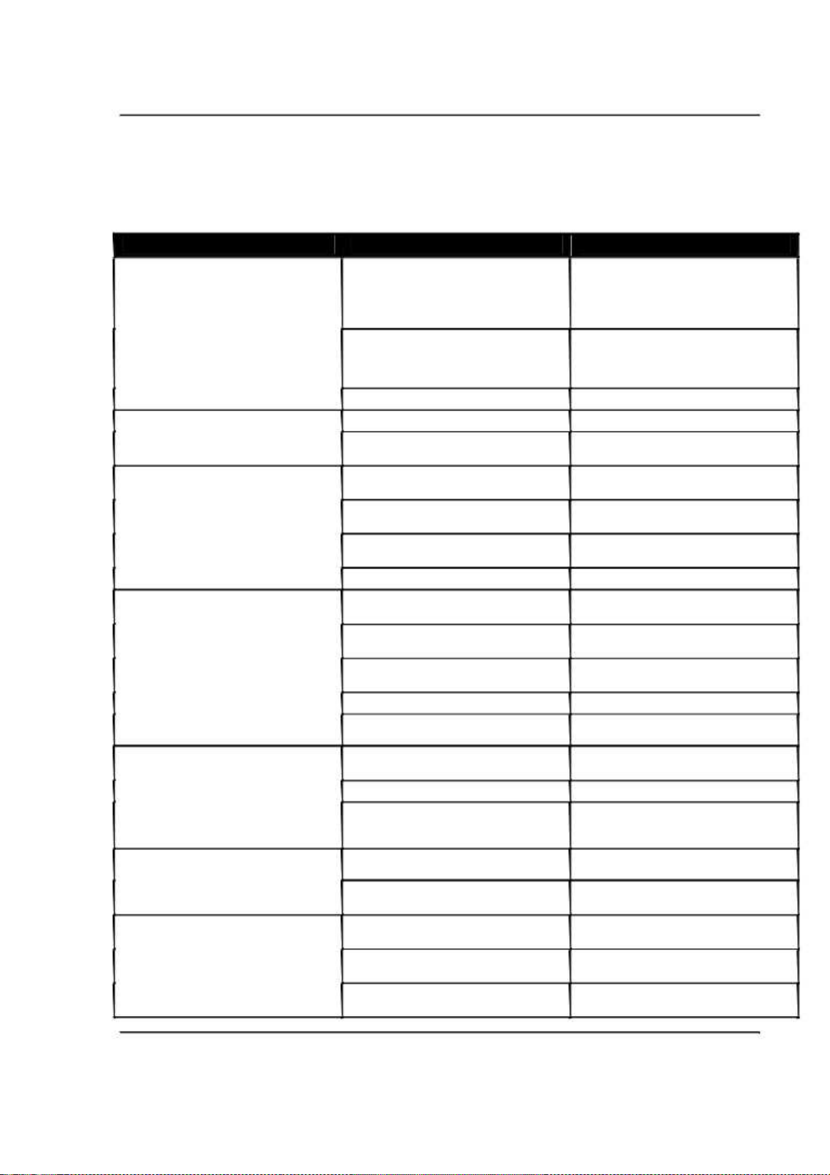
Troubleshooting
General Troubleshooting
Problem Possible Cause Solution
Troubleshooting
No communications. All headsets have The base station has no power.
green LED is flashing.
A single headset has green LED flashing Headset is not registered to base station. Register the headset.
No vehicle alert tone in all headsets. No power to the external vehicle detector.
All headsets will not go into Standby This is normal when a pulse (air switch) Press the Page switch to silence the menu
(silence) when the vehicle leaves the menu type of vehicle detector is used.
sign.
Audio on all headsets cuts out or is The Backup Intercom is on (the switch is Disengage the Backup Intercom switch on
interrupted. engaged). the base station.
Inbound audio cuts out (but outbound audio The AEC level is too high.
is okay)
No Talk or listen from the menu sign when The backup switch on the base station is
using the backup wired intercom. The XT-1 not in the correct position.
system works OK.
Headsets are not registered to Base
Station.
The Base Station is defective.
Defective headset. If the other headsets register OK, the single
Vehicle detector is “locked up.”
The base station alert tone volume is set
too low.
System is in Always On order taking mode.
There is a large metal object near the loop
in the driveway (if a loop is used).
The Loop detector is “locked up.”
Defective vehicle detector.
System is in Always On order taking mode.
Loose or frayed wiring. Call for authorized service.
Poor location of Base Station antennae Relocate the Base Station, or antennae.
(behind large metal objects, too far from
work area, etc.).
The headset is too close to loud ambient
noise.
No power to the backup intercom.
The volume controls are set too low on the
backup intercom.
Make sure the power transformer is
plugged into the wall outlet and into the base
station power receptacle. If the LCD display
does not come on, check for power at the
wall outlet.
Register headsets
Call for authorized service.
headset needs repair.
Plug the vehicle detector into power outlet
or replace the detector fuse.
Remove power to vehicle detector for a few
seconds to reset the detector.
Adjust alert tone volume.
Change the talking mode.
microphone.
Remove the object.
Unplug the loop detector from the AC outlet
and plug it back in to reset the detector.
Call for authorized service.
Change the talking mode.
Reduce the AEC level.
Move the headset away from sources of
loud ambient noise.
Turn the backup switch ON.
Turn the backup intercom on or plug in its
power transformer.
Turn the volume controls up.
3M™ Wireless Communication System, Model XT-1: Operating Instructions Rev 1.0 © 3M 2007 November
Page 37 of 48
Page 37
Troubleshooting
Problem Possible Cause Solution
No Talk or Page to other headsets from a Worn or defective Talk or Page switch. Call for authorized service.
single headset, or Talk or Page buttons
require excessive pressure to operate.
Low Talk volume on a single headset. The holes in front of the microphone are Call for authorized service.
Louder Talk volume or feedback from a Volume setting on headset is too high. Power off and power on headset to reset
single headset. volume level.
The “hands free” function does not work. The system is operating in half duplex Hands Free is disabled in half duplex mode.
No vehicle alert tone in headset. Backup switch not completely pressed (i.e., Press the other button into the correct
Defective backup intercom or wiring. Call for authorized service.
Defective headset.
plugged with dirt or grease.
Operator is not positioning the microphone Adjust/reposition the headset
correctly. microphone(s).
Defective headset. Call for authorized service.
Volume setting on headset is too low. Power off and power on headset to reset
volume level.
The holes in back of the microphone are Call for authorized service.
plugged with dirt or grease.
mode.
Hands free order taking mode not selected. Select hands free order taking mode in the
base station.
one of the other two buttons is pressed). location.
Battery and Battery Charger Troubleshooting
Problem Possible Cause Solution
No lights come on when a battery is Dirty contacts on battery or charger. Clean contacts on battery and charger.
inserted into charger.
Short battery life. Worn out batteries. Replace battery.
The green light on the charger never comes Defective battery. Replace the battery.
on.
3M™ Wireless Communication System, Model XT-1: Operating Instructions Rev 1.0 © 3M 2007 November
Page 38 of 48
No power to charger. Make sure power transformer is plugged
into charger and a “live” outlet.
Defective battery. Try a known good battery.
Defective charger. Call for authorized service.
Wrong type of power transformer used for Make sure power transformer is marked
charger. “Secondary Voltage 14 VAC.”
Page 38
Appendix: Base Station Specifications
Appendix: Base Station Specifications
Physical
Parameter Specification or Requirement
Dimensions (l x w x d) 20 in. x 11½ in. x 2 in.
(51 cm x 29 cm x 5 cm)
Electrical
Parameter Specification or Requirement
Input Power 120 VAC, 50/60 Hz, 15A
Radio Frequency 2.4 GHz ISM
Speaker outputs 5W
Standard 3-prong outlet required
(station includes AC adapter)
Functional
Parameter
Maximum number of order points
per base station
Maximum number of headsets
per base station
Maximum number of vehicle
detectors per base station
Maximum number of greeter
modules per base station
Maximum number of timer vehicle
detector modules per base station
Specification or Requirement
1
more than 15
3
1
3
3M™ Wireless Communication System, Model XT-1: Operating Instructions Rev 1.0 © 3M 2007 November
Page 39 of 48
Page 39

Appendix: Base Station Specifications
3M™ Wireless Communication System, Model XT-1: Operating Instructions Rev 1.0 © 3M 2007 November
Page 40 of 48
Page 40

Appendix: Greeter Module
Greeter Setup
Enter the Greeter Configuration Menu
Play Greeter Message
Select Specific Greeter Messages
Appendix: Greeter Module
The greeter module is an accessory that stores prerecorded messages and plays
them back when vehicles arrive.
You can record a series of messages then select or combine them to convey
standard messages and reduce time and errors.
All of the greeter settings are located in a top-level “Greeter Setup”
configuration menu.
Perform the following procedure to enter the greeter configuration menu:
1. Enter the base station configuration mode, see page 9.
2. Press and release
Perform the following procedure to listen to the current greeter messages:
1. Enter the greeter configuration menu, see above.
2. Select
3. Press
You can store up to four different greeter messages, then select one or more of them
to be played at any given time. Perform the following procedure to enable specific
greeter messages:
1. Enter the greeter configuration menu, see above.
2. Select
3. Change the value of the desired message (1-4) to ON or
4. Return to step 3 if you want to change additional messages.
1 Play Greeter Messages
plays on the headsets.
Service
to stop playing when finished.
1 Play Greeter Messages
Mode
until the
Greeter Setup
. The currently-selected message
.
menu appears.
OFF
.
Change Playback Mode
Perform the following procedure to change the greeter playback mode.
1. Enter the greeter configuration menu, see above.
2. Select
3. Change the value of the playback setting. Your choices are:
3M™ Wireless Communication System, Model XT-1: Operating Instructions Rev 1.0 © 3M 2007 November
1 Play Greeter Messages
•
ALTERNATING
pulls up to the customer order point. Multiple messages must be
selected.
•
PLAY ONCE
that pulls up to the customer order point.
•
REPEATEDLY
the order taker starts to speak.
—A different message plays for each vehicle that
—All messages selected play once for every vehicle
—All messages selected play continuously until
>
Playback
.
Page 41 of 48
Page 41

Appendix: Greeter Module
Perform the following procedure to record (store) a new greeter message:
Notes:
If you store a new greeter message in an occupied slot, the old greeter
message will be permanently erased.
Each recorded message can be no more than 15 seconds long.
1. Put on a working headset with the power on.
2. At the base station, enter the greeter configuration menu, see page 41.
3. Select
4. Scroll to
2 Record Greeter Messages
where “x” represents the greeting number you want to record.
Record
5. Press and hold the Page button on the headset.
6. Press and hold
want to record.
7. When finished, release
8. To hear the new greeting played back, scroll to
Service
.
Note:
Instead of recording a live greeting from a headset, you can use a message that
was prerecorded and saved on a media recording/playback device, such as a
CD or MP3 player or on the hard drive on a computer. Connect the device to
the AUX AUDIO IN jack on the bottom of the base station, and use the
device’s controls to start and stop the playback by using the base station’s
Service button.
Change Playback Delay Time
Playback delay time is the number of seconds between when the vehicle detector
detects a vehicle and when the greeter begins to playback the message.
>
Record Message >X<
.
Service
on the base station and speak the message you
, then release the page button.
Service
Playback
and press
Perform the following procedure to change the playback delay time:
1. Enter the greeter configuration menu, see page 41.
2. Navigate to
>XX< Seconds
3 Greeter Setup >Playback After Delay Of
where “xx” represents the current number of seconds.
3. Change the number of seconds to a new value. The range is 0 to 15
seconds.
Set Greeter Playback through Headsets
You have the choice of allowing the greeting to be played through the headset in
addition to being played to the customer at the order point.
Perform the following procedure to enable or disable playback through headsets:
1. Enter the greeter configuration menu, see page 41.
2. Change the value for
Headsets?
to
3 Greeter Setup
YES
or NO. Selecting YES means the greeting will play
>
Playback To The
on the headsets as well as the order point. Selecting NO means it will
only be heard at the order point (and the monitor if selected below).
Set Playback through Monitor
You have the choice of allowing the greeting to be played through the
monitoring speaker in addition to being played to the customer at the ordering
point.
3M™ Wireless Communication System, Model XT-1: Operating Instructions Rev 1.0 © 3M 2007 November
Page 42 of 48
Page 42

Perform the following procedure to enable or disable playback through the
monitor:
1. Enter the greeter configuration menu, see page 41.
2. Change the value for
Monitor?
to
3 Greeter Setup
YES
or NO. Selecting
on the monitor as well as the order point. Selecting NO means it will
only be heard at the order point (and the headsets if selected above).
Turn on Tone to Headsets During Greeter Playback
If the greeting is not playing over the headsets, a continuous tone can be played
while the customer is hearing the greeting. This permits the order taker to know
when the greeting is playing and when it has stopped.
To enable or disable the tone during greeter playback:
1. Enter the greeter configuration menu, see page 41.
2. Change the value for
During Playback?
3 Greeter Setup
to
YES
or NO. Selecting YES means the tone will
play on the headsets. Selecting NO means it will not play on the
headsets.
Appendix: Greeter Module
>
Playback To The
YES
means the greeting will play
>
Tone To Headsets
Turn on Restaurant Closed Playback Message
You can assign a standard message to be played to customers during hours when the
restaurant is closed. The clock and store hours must be set correctly, and the actual
message must be recorded, then it can be set to activate automatically whenever the
restaurant is closed.
To turn on the restaurant closed playback message:
Notes:
Make sure that the clock setting and store hours are correct before enabling the
restaurant closed message playback.
1. Enter the greeter configuration menu, see page 41.
2. Change the value for
Playback Message
3 Greeter Setup
to
1, 2, 3, 4
>
Restaurant Closed
, or
OFF
. Selecting 1, 2, 3, or
4
means the corresponding message will play when the store is closed.
Selecting
OFF
means a message will never be played.
Note:
When you have a restaurant closed playback message, “CLS” will appear in the
numbered slot (1, 2, 3, or 4) for the number you select.
Turn on External Detector Playback Message
If an external detector is used and connected to the EXT_MSG trigger pin on the
base station circuit board, you can assign a message to be played back whenever the
external detector is activated.
To turn on the external detector playback message:
1. Enter the greeter configuration menu, see page 41.
2. Change the value for
Message
to
1, 2, 3, 4
3 Greeter Setup
, or
OFF
. Selecting 1, 2, 3, or 4 means the
>
External Playback
corresponding message will play when the external detector is
activated. Selecting
OFF
means a message will never be played.
3M™ Wireless Communication System, Model XT-1: Operating Instructions Rev 1.0 © 3M 2007 November
Page 43 of 48
Page 43

Appendix: Greeter Module
3M™ Wireless Communication System, Model XT-1: Operating Instructions Rev 1.0 © 3M 2007 November
Page 44 of 48
Page 44

Index
Index
Acoustic echo ...
Acoustic echo cancelling ...
Adding headsets ...
Adjustment Slide ...
AL (automatic latching) ...
Alert tone, none ...
Alternating, greeter ...
Always On (mode) ...
Audio mode ...
Automatic standby modes ...
backup intercom ...
Base station setup ...
Battery ...
general information ...
low ...
short life...
Battery Release ...
Boot ...
Caution definition ...
Change Battery Now
Heard on headset ...
Charge battery ...
Charger
no lights or not working ...
Charger, battery ...
CLS...
Configuration...
Contacts, battery ...
Create templates ...
Cross lane mode ...
Crossing, lane ...
cut out (headset) ...
Date ...
Dead battery ...
Delay time, greeting ...
Dimensions ...
Display
buttons ...
navigating ...
3M™ Wireless Communication System, Model XT-1: Operating Instructions Rev 1.0 © 3M 2007 November
.. 17 Disposal, battery.................................................34
... 17 Ear cup .................................................................26
. 15 Ear pad .................................................................33
... 25 Echo .....................................................................17
. 29 Enter (Select) button ...........................................10
.. 37 Ethernet port... ....................................................11
... 41 Factory settings ... ................................................23
... 29 FCC information ...................................................8
.. 18 Feedback ..............................................................38
. 29 Fitting (headset) ... ...............................................26
. 24 Full duplex
.. 28 definition ... ......................................................18
. 26 Global settings....................................................17
. 35 Green light, charger......................................34, 38
... 34 Greeter
. 38 setup ..................................................................41
... 26 tone ...........................................................................43
.. 23 Greeter messages................................................14
. 7 Half duplex
definition ..........................................................18
.. 27 Hands free
. 34 not working ... ..................................................38
Headband pad ........................................................33
... 38 Headset
.. 33 auditory messages ...........................................27
... 43 cleaning ... ........................................................27
... 11 cuts out ..............................................................37
. 33 goes into standby ..............................................37
. 23 registering.......................................................15
. 31 Headsets ...............................................................25
.. 19 Holiday scheduling ............................................21
. 37 Inbound listen ........................................................13
.. 17 Inbound microphone
. 38 noise reduction level .......................................16
. 42 volume............................................................12
... 39 Indicator LED ... ..................................................25
Input Power ..........................................................39
... 10 Installation settings.......................................22, 23
... 9 Intended use ... .......................................................7
Lane 1 or Lane 2
heard on headset ..............................................27
Lane crossing .......................................................19
Lane mode ... ...........................................................30
Language
prompts... ........................................................17
Page 45 of 48
Page 45

Listen modes........................................................ 29 PTT (Push to talk) ................ .. See Talking modes
Listing headsets ... ............................................... 16 Pull ahead prompt ............................................. . 19
Load templates .................................................... 23 Reboot ............................................................... . 23
Low battery.......................................................... 34 Registering headsets ... ...................................... . 15
Maintenance ... .................................................... 33 Regular site schedule.......................................... 21
ML (manual latching) ......................................... 29 Removing headsets.......................................... ... 16
Mode Repeatedly, greeter... ....................................... ... 41
audio ............................................................... 18 Restaurant closed message ................................ 43
cross lane ... ..................................................... 31 Revision levels ................................................... 23
lane .................................................................. 30 Rotate ear cup... ................................................ .. 26
order taking............................................. .. 20, 28 Run mode ........................................................... 28
run.................................................................... 28 Safety rules ......................................................... .. 7
service ............................................................... 9 Schedule ............................................................ . 21
split lane .......................................................... 31 Select greeter messsage ................................... .. 41
talking ............................................................. 29 Self monitoring............................................. 16, 21
volume ............................................................ 31 Service (Shift) button ......................................... 11
Mode (Exit) button ... .......................................... 10 Site information... ............................................... 21
Monitor volume .................................................. 13 Site scheduling ................................................ ... 20
Night volume ...................................................... 15 Specifications ..................................................... 39
No alert tone ... .................................................... 37 Split lane mode... ............................................. ... 31
No communication ............................................. 37 Storage, battery ... ............................................. .. 34
Noise reduction.................................................... 16 Store closed prompt............................................ 19
Noise reduction level .......................................... 16 System date and time ....................................... .. 17
On/Off (headsets) ... ............................................ 26 T1 and T2 ......................................................... .. 25
Once each, greeter ... ........................................... 41 Talk
Operation ............................................................ 25 modes ............................................................ . 29
Order point modes .............................................. 29 Talk Buttons ...................................................... . 25
Order taking mode ........................................ 20, 28 Talking modes ................................................... . 29
Out of Range ....................................................... 27 Templates ......................................................... .. 23
Outbound greeter message volume..................... 13 Time ... ............................................................... . 17
Outbound talk ..................................................... 13 Transducer Mode ............................................... 20
volume ............................................................ 12 Troubleshooting ................................................ . 37
Outside (mode) ................................................... 29 Two base systems... .......................................... .. 18
Page (headset)...................................................... 26 User passcode ... ................................................. 22
Page channel ....................................................... 18 Vehicle
Page messages .................................................... 14 alert volume................................................... . 12
Paging approach ...................................................... ... 14
definition ......................................................... 14 detector modes ............................................. .. 29
Paging problem.................................................... 38 present ......................................................... ... 14
Passcodes ............................................................ 22 Volume ............................................................... 12
Play greeter message ... ....................................... 41 headset ... ........................................................ 26
Playback mode, changing ... ............................... 41 inbound microphone.................................... ... 12
Product Overview ................................................. 7 mode ............................................................ ... 31
Prompt monitor ......................................................... .. 13
language........................................................... 19 night ... ............................................................ 15
pull ahead ........................................................ 19 outbound greeter message ............................. 13
store closed ..................................................... 19 outbound talk... ............................................. .. 12
vehicle alert ................................................... . 12
Warning definition ........................................... .. 7
3M™ Wireless Communication System, Model XT-1: Operating Instructions Rev 1.0 © 3M 2007 November
Page 46 of 48
Page 46

Index
3M™ Wireless Communication System, Model XT-1: Operating Instructions Rev 1.0 © 3M 2007 November
Page 47 of 48
Page 47

Building and Commercial Services Division
Food Services Business
3M Center
St. Paul, MN 55144-1000
Printed in U.S.A.
© 3M 2007 November
78-6911-4939-3 Rev 1.0
Page 48

FCC & SAFETY STATEMENT
FCC STATEMENT
This device complies with part 15 of the FCC Rules. Operation is subject to the following two conditions :
(1) this device may not cause harmful interference,
(2) this device must accept any interference received, including interference that may cause undesired operation.
3M™ Wireless Communication System, Model XT-1: Operating Instructions Rev 1.0 © 3M 2007 November
Page I
Page 49

FCC & SAFETY STATEMENT
SAFETY STATEMENT
BASE STATION
ATTENTION
The product have to be powered by an external power of 12V with a classification level 3, which are
defined by references : UL listed, (E183744), SCEPTRE, model: PS-1266APL6A, input: 100-240Vac,
47-63Hz, 1.3A; output: 12Vdc, 6.6A max.
The product should not be used on a computer room as per the standard ANSI/NFPA 75.
Attention
The is a risk of explosion if the battery is replaced by an invalidated battery.
Use only the validated battery
Recycle the battery as per instructions
HEAD SET
ATTENTION
Use only the validated battery with the reference below :
ICP 633048A1 By LG Chem
Recycle the battery as per instructions.
3M™ Wireless Communication System, Model XT-1: Operating Instructions Rev 1.0 © 3M 2007 November
Page II
 Loading...