

Page 1

Operations Manual
DOPSM2064X012
October 2019
TESCOM™ ER5000 Series
User Manual
Do not attempt to select, install, use or maintain
this product until you have read and fully
understood the Safety, Installation & Operations
Precautions section of this manual.
WARNING
If your application is rated as a Hazardous Location,
you MUST use model ER5050. Models ER5000,
ER5020, ER5040, ER5100 and ER5110 are not
intended for or rated for use in Hazardous Locations.
Page 2

Safety, InStallatIon &
BACK
o
www.emerson.com/tescom
peratIonS precautIonS
2
Page 3

ER5000 — 3Safety, Installation & Operations Precautions
BACK
TESCOM™ ELECTRONIC CONTROLLERS
WARNING
DO NOT ATTEMPT TO SELECT, INSTALL, USE OR MAINTAIN THIS
CONTROLLER OR ACCESSORY UNTIL YOU HAVE READ AND FULLY
UNDERSTOOD THESE INSTRUCTIONS.
BE SURE THIS INFORMATION REACHES THE OPERATOR AND STAYS WITH THE
PRODUCT AFTER INSTALLATION.
DO NOT PERMIT UNTRAINED PERSONS TO INSTALL, USE OR MAINTAIN THIS
CONTROLLER OR ACCESSORY.
IMPROPER SELECTION, IMPROPER INSTALLATION, IMPROPER MAINTENANCE,
MISUSE OR ABUSE OF THIS CONTROLLER OR RELATED ACCESSORIES CAN CAUSE
DEATH, SERIOUS INJURY AND/OR PROPERTY DAMAGE.
OXYGEN SERVICE REQUIRE S SPECIAL EXPERTISE AND KNOW LEDGE OF SYSTEM
DESIGN AND MATERIAL COMPATIBILITY IN ORDER TO MINIMIZE THE POTENTIAL
FOR DEATH, SERIOUS INJURY AND/OR PROP ERTY DAMAGE.
Possible consequences include but are not limited to:
• High velocity uid (gas or liquid) discharge
Electrocution
•
• Parts ejected at high speed
• Contact with uids that may be hot, cold, toxic or otherwise injurious
• Explosion or burning of the uid
• Lines/hoses whipping dangerously
• Damage or destruction to other components or equipment in the system
CAUTION
SAFETY PRECAUTIONS
1. Read and underst and the user’s manual before operating the contro ller.
2. Inspe ct the control ler and accessor ies before each use.
3. Operate the un it only under specied environment al conditions .
4. Follow instructions in the manuals for proper wiring.
5. Never co nnect the cont roller or accessorie s to a supply source having a voltag e
greater t han the maximum rated vo ltage of this controll er or accessor y.
6. Nev er connect the c ontroller or a ccessories to a su pply source hav ing a pressure
greater t han the maximum rat ed pressure of this co ntroller or acces sory.
7. Never use anything bu t clean dry inert gases or air into the
electropneumatic controller.
8. Star t up sequence for e lectropne umatic control lers is:
a. Fe edback loop mus t be installed a nd operationa l.
b. Elec trical power should be applie d and system set point reduced to
its low est pressure ou tput before turning on the pneumatic supply to
the controller.
9. Refer to produc t label (modica tion specic) for maximum inlet p ressures. If
this rated pressure cannot be found, cont act your local TESCO M representa tive
for the ra ted pressure pr ior to installation an d use. Verify the designed pressu re
rating of all equi pment (e.g., supply lines, t tings, connec tions, lter s, valves,
gauges, etc.) in your s ystem. All must b e capable of handling the supply a nd
operating pressure.
www.emerson.com/tescom
Page 4

ER5000 — 4Safety, Installation & Operations Precautions
BACK
10. Cl early establ ish ow direct ion of the uid before installat ion of controll ers,
regulators, valves and accessories. It is the responsibility of the user to install
the equipment in the correct direction.
11. Remove pressure from the system before tighteni ng ttings, ga uges
or components.
12. Ne ver turn controller, regulator or v alve body. Instead, hold the contr oller body
and turn tti ng nut.
13. If a controller, regul ator or valve leaks or mal functions, t ake it out of
service immediately.
14. Do n ot modify equ ipment or add at tachments not approved by
the manufacturer.
15. Apply pr essure to the sys tem gradually, avoiding a sudden surge of uid o r
pressure shock to the equipment in the sy stem.
16. Reg ulators are not shut-of f valves. Inst all a pressure relief de vice downstream
of the regulator to prote ct the process equipm ent from operating pressure
increas es. Shut off the supply p ressure when the regulator is not in use.
17. Periodic inspection and scheduled maintenance of your equipment is required
for continued safe operation.
18. Th e frequency of ser vicing is the responsibilit y of the user based o n the
applic ation. Never allow problems or l ack of maintenance to go unre ported.
19. Read and follow precautions on compressed gas cylinder labels.
20. It is impor tant that you analyze a ll aspects of your applicati on and review
all available informat ion concerning the pro duct or syste m. Obtain, read
and understand the Ma terial Safet y Data Sheet (MSDS) for each uid used in
your system.
21. Never use materials for controllers, regulators, valves or accessories that are
not compa tible with the uids being used.
22. Users must test under normal operating conditions to determine suitability of
materials in an application.
23. Vent u ids to a safe environment and in an area away from employees. B e sure
that vent ing and disposal m ethods are in acco rdance with Fed eral, State and
Local requirement s. Locate and construc t vent lines to prevent condensat ion
or gas accumulati on. Make sure the ven t outlet is not obstruc ted by rain, snow,
ice, vegetation, insects, birds, etc. Do not interconnect vent lines; use separate
lines if m ore than one vent is n eeded.
24. Do not lo cate controll ers, regulators, val ves or accessories using amma ble
uids near open ames or any other source of igni tion. Use of Hazardous Location
contro llers may be ne cessary to be i n accordance wit h local elec tric codes.
25. So me uids, when burning, do not ex hibit a visible ame. Use extre me caution
when inspect ing and/or servicing systems using ammable uids to avoi d
death or serious injur y to employees. P rovide a device to warn em ployees of
these dangerous conditions.
26. Many gases can cause suffo cation. Make cer tain the area is well vent ilated.
Provide a device to warn e mployees of lack of Oxygen.
27. Ne ver use oil or grease on these contro llers, regul ators, valves or access ories.
Oil and gr ease are easily ign ited and may combi ne violently w ith some uids
under pressure.
28. Have emergency e quipment in the area if toxic or ammable uids are used.
29. Up stream lters are recommended for us e with all uids.
30. Do n ot bleed system by loos ening ttings.
31. Pr event icing of the e quipment by removing e xcess moisture f rom the gas.
32. Always us e proper thread lubricants a nd sealants on tapere d pipe threads.
www.emerson.com/tescom
Page 5

ER5000 — 5Safety, Installation & Operations Precautions
BACK
INSTALLATION
Inspec t the controll er and accessories for physical d amage and contam ination.
Do not connect the contr oller or accessory if you dete ct oil, grease or damaged
part s. If the controller or accessory is damaged, co ntact your lo cal TESCOM™
representative to have the controller cleaned or repaired.
WARNING
Make sure t hat the compone nts and materia ls used in the fluid hand ling
system a re compatible w ith the fluid an d have the proper pr essure rating .
Make sure t hat the compone nts used in the electronic system are
compatible with and have the proper voltage rating.
REPAIR SERVICE
If a controller leaks or malfunctions, take i t out of servic e immediately. You must
have inst ructions before doing any mai ntenance. Do not make a ny repairs you do
not understa nd. Have qualie d personnel make repair s. Return any equipment
in need of s ervice to your equipment supp lier for evaluat ion and prompt se rvice.
Equipment is restored to the ori ginal factor y performance spe cications, i f
repair able. There are at fee rep air charges for eac h standard mod el. The original
equipment warranty applies after a complete overhaul.
WARNING
SAFE COMPONENT SELECTION
1. Consid er the total sys tem design when selec ting a component to ensure s afe,
trouble-free performance.
2. The use r is responsible for assur ing all safety and warning requirem ents of the
application are met through his/her own analysis and testing.
3. TESCOM may sugg est material for us e with spe cic media upon request.
Suggestions are based on technical compatibility resources through
associations and manufacturers. TESCOM does NOT guarantee materials to be
compatible with speci c media — THIS IS THE RE SPONSIBILITY OF THE USER!
4. Component function, adequate ratings, proper installation, operation and
maintenance are the responsibilities of the system user.
5. The user is responsible to be in accordance with all the necess ary mechanical
and electrical codes required for installation and operation of the system. These
requirements include but are not limited to all Hazardous Location controllers.
6. The use r is responsible for the select ion of the proper model number of t he
controller that would meet the application’s possible hazardous environment
or conditions.
WARNING
Do not mod ify equipme nt or add attachments not approved by
the manufacturer.
www.emerson.com/tescom
Page 6

ER5000 — 6Safety, Installation & Operations Precautions
BACK
TESCOM™ REGULATORS
WARNING
DO NOT ATTEMPT TO SELECT, INSTALL, USE OR MAINTAIN THIS
REGUL ATOR, VALVE OR ACCESS ORY UNTIL YOU HAVE RE AD AND FULLY
UNDERSTAND THESE INSTRUCTIONS.
BE SURE THIS INFORMATION REACHES THE OPERATOR AND STAYS WITH THE
PRODUCT AFTER INSTALLATION.
DO NOT PERMIT UNTRAINED PERSONS TO INSTALL, USE OR MAINTAIN THIS
REGULATOR, VALVE OR ACCESSORY.
IMPROPER SELECTION, IMPROPER INSTALLATION, IMPROPER MAINTENANCE,
MISUSE OR ABUSE OF REGULATORS, VALVES OR RELATED ACCESSORIES CAN CAUSE
DEATH, SERIOUS INJURY AND/OR PROPERTY DAMAGE.
OXYGEN SE RVICE REQUIR ES SPECIAL EX PERTISE AND K NOWLEDGE OF SY STEM
DESIGN AND MATERIAL COMPATIBILITY IN ORDER TO MINIMIZE THE POTENTIAL
FOR DEATH, SERIOUS INJURY AND/OR PROPERTY DAMAGE.
Possible consequences include but are not limited to:
• High velocity uid (gas or liquid) discharge
• Parts ejected at high speed
• Contact with uids that may be hot, cold, toxic or otherwise injurious
• Explosion or burning of the uid
• Lines/hoses whipping dangerously
• Damage or destruction to other components or equipment in the system.
www.emerson.com/tescom
CAUTION
SAFETY PRECAUTIONS
1. Inspe ct the regulat or, valve and a ccessories before each use.
2. Never co nnect regulators , valves or access ories to a supply s ource having a
pressure great er than the maximum rate d pressure of the r egulator, valve
or accessory.
3. Refer to produc t label (model specic) for ma ximum inlet pressure s. If this
rated pr essure cannot b e found, contac t your local TE SCOM represent ative for
the rate d pressure pri or to installation and us e. Verif y the designed pr essure
rating of all equi pment (e.g., supply lines, t tings, connec tions, lter s, valves,
gauges, etc.) in your s ystem. All must b e capable of handling the supply a nd
operating pressure.
4. Clear ly establish ow direction of the ui d before installatio n of regulators,
valves and accessories. It is the r esponsibilit y of the user to ins tall the
equipment in the correct direction.
5. Remove pressur e from the syst em before tightening t tings, gauges
or components.
6. Never t urn regulator o r valve body. Instead hold r egulator or val ve body and
turn t ting nut.
7. If a regulator or valve leaks or malfunctions, take it out of ser vice immediately.
8. Do not mo dify equipm ent or add atta chments not app roved by
the manufacturer.
9. Appl y pressure to the s ystem gradual ly, avoidin g a sudden surge of uid or
pressure shock to the equipment in the sy stem.
Page 7

ER5000 — 7Safety, Installation & Operations Precautions
BACK
10. Reg ulators are not shut-of f devices. Ins tall a pressure relief d evice downstream
of the regulator to prote ct the process equipm ent from overpr essure
conditions. Shut off t he supply pressure whe n the regulator is not in use.
11. Periodic inspection and scheduled maintenance of your equipment is required
for continued safe operation.
12. Th e frequency of ser vicing is the responsibilit y of the user based o n
the application.
13. Ne ver allow problems or lack of mainte nance to go unrepo rted.
14. Read and follow precautions on compressed gas cylinder labels.
15. It is impor tant that you analyze a ll aspects of your applicati on and review
all available informat ion concerning the pro duct or syste m. Obtain, read
and understand the Ma terial Safet y Data Sheet (MSDS) for each uid used in
your system.
16. Ne ver use materials for regu lators, valve s or accessories that are n ot
compatible wi th the uids being used.
17. User s must test component s for material compatibi lity with the system
operat ing conditions prior to use in the syste m.
18. Vent u ids to a safe environment and in an area away from employees. B e sure
that vent ing and disposal m ethods are in acco rdance with Fed eral, State and
Local requirement s. Locate and construc t vent lines to prevent condensat ion
or gas accumulati on. Make sure the ven t outlet is not obstruc ted by rain, snow,
ice, vegetation, insects, birds, etc. Do not interconnect vent lines; use separate
lines if m ore than one vent is n eeded.
19. Do not locate re gulators, valves or accessor ies controlling ammable uid s near
open am es or any other sour ce of ignition. Use of Hazar dous Location contro llers
may be necessar y to be in accordan ce with local el ectric
codes.
20. So me uids when bur ning do not exhibit a visi ble ame. Use extreme c aution
when inspect ing and/or servicing systems using ammable uids to avoi d
death or serious injur y to employees. P rovide a device to warn em ployees of
these dangerous conditions.
21. Many gases can cause suffo cation. Make cer tain the area is well vent ilated.
Provide a device to warn e mployees of lack of Oxygen.
22. Ne ver use oil or grease on these regula tors, valves o r accessories. Oil and gr ease
are easil y ignited and may co mbine violent ly with some uids under pressu re.
23. Have emergency e quipment in the area if toxic or ammable uids are used.
24. Up stream lters are recommended for us e with all uids.
25. Do n ot bleed system by loos ening ttings.
26. Pr event icing of the e quipment by removing e xcess moisture f rom the gas.
27. Always us e proper thread lubricants a nd sealants on tapere d pipe threads.
www.emerson.com/tescom
Page 8

ER5000 — 8Safety, Installation & Operations Precautions
BACK
INSTALLATION
WARNING
Investigate and apply the most recent standards for Hazardous Locations for
your area set by ANS I, ISO and OSHA, as well as all elec trical codes a nd fire and
safet y standards, t o determine if you r application w ill require a Hazardo us
Location model.
CAUTION
Do not open packaging until ready for installation or in a clean environment. Product
is clean ed in accordan ce with CGA 4.1 and AST M G93, Verificat ion Type 1, Test 1 and
Test 2. With p eriodic veri fication of c leaning pro cess to MIL-STD-1330D.
WARNING
Make sure t hat the compone nts and materia ls used in the fluid hand ling
system a re compatible w ith the fluid an d have the proper pr essure rating .
Failure to d o so can result in death, se rious injury and/or propert y damage.
Inspect the regulator, valve and accessories for physical damage and contamination.
Do not con nect the regu lator, valve or acces sory if you de tect oil, grea se or damaged
part s. If the regul ator, valve or access ory is damage d, contact yo ur local TESCO M™
representative to have the regulator cleaned or repaired.
REPAIR SERVICE
If a regulator or valve lea ks or malfunc tions, take it ou t of service immediat ely.
You must have instruc tions before doing any mainten ance. Do not make any
repair s you do not under stand. Have qual ied personnel make repairs. Retur n any
equipm ent in need of ser vice to your equipment su pplier for evaluation and prom pt
serv ice. Equipment is r estored to the origina l factory perfo rmance specicatio ns,
if repai rable. There are at fee repair cha rges for each standard mo del. The original
equipment warranty applies after a complete overhaul.
CAUTION
PROPER COMPONENT SELECTION
1. Consid er the total sys tem design when selec ting a component for use in
a system.
2. The use r is responsible for assur ing all safety and warning requirem ents of the
application are met through his/her own analysis and testing.
3. TESCO M may suggest material for use with speci c media upon request.
Suggestions are based on technical compatibility resources through
associations and manuf acturers. TESCOM does NOT guarante e materials to be
compatible wi th specic media -- THIS IS THE RE SPONSIBILITY OF T HE USER!
4. Component function, adequate ratings, proper installation, operation and
maintenance are the responsibilities of the system user.
WARNING
Do not mod ify equipme nt or add attachments not approved by the
manufacturer. Failure to do s o can result in death, ser ious injury and/or
property damage.
www.emerson.com/tescom
Page 9

table of contentS
BACK
www.emerson.com/tescom
9
Page 10

ER5000 — 10Table of Contents
BACK
Table of Contents
Safety, Installation & Operations
Precautions 2
TESCOM™ ELECTRONIC CONTROLLERS . . . . . 3
TESCOM REGULATORS . . . . . . . . . . . . . 6
Table of Contents 9
Table of Contents . . . . . . . . . . . . . . . 10
Conventions of This Manual . . . . . . . . . . 13
Navigating This Manual . . . . . . . . . . . . 13
Features and Specifications 14
ER5000 Series Part Numbering System . . . . 15
ER5000 Standard Features . . . . . . . . . . 15
ER5000 Dimensions – Side Views . . . . . . . 16
ER5000 Dimensions – Top and Bottom View . . 17
ER5050 Hazardous Location Model . . . . . . 18
Dimensions – Side Views . . . . . . . . . . . 18
ER5050 Hazardous Location Model . . . . . . 19
Dimensions – Top and Bottom View . . . . . . 19
ER5000 Specifications . . . . . . . . . . . . 20
Hazardous Location Model (ER5050)
Specifications . . . . . . . . . . . . . . . . 22
Accessories . . . . . . . . . . . . . . . . . . 24
What’s New 25
New Features . . . . . . . . . . . . . . . . . 26
Replacing an ER3000 with an ER5000 . . . . . 27
How It Works 29
The ER5000: How It Works . . . . . . . . . . 30
Understanding PID Controllers . . . . . . . . 31
PID Controllers: Three Components
Are Better Than One 32
A Typical PID Control System 33
Tuning a PID Controller 35
Rules of Thumb for PID Tuning 35
The ER5000: Typical Application
(Non-Hazardous Location) . . . . . . . . . . 39
Controlling System Pressure 39
A Note Concerning Non-Venting
Regulators in Closed Loop Applications 41
Monitoring System Control Limits 42
The ER5000: Control Modes . . . . . . . . . . 43
Internal Feedback Mode 43
External Feedback Mode 43
Cascade Mode 43
Glossary of Terms 44
Terms Relating to PID Controllers
and Controller Tuning . . . . . . . . . . . . 45
Terms Relating to Regulators . . . . . . . . . 52
Getting Started 57
Before You Begin . . . . . . . . . . . . . . . 58
ER5000 Quick Reference: Jumpers,
Terminal Blocks and Wires and LEDs . . . . . 59
Verify your shipment . . . . . . . . . . . . . 60
Additional items not included: 61
Tools you will need for the installation: 61
Additional items and tool you will need for
an installation in a Hazardous Location: 61
Verify the configuration of your application . . . . 62
Verify that all operational requirements
have been met . . . . . . . . . . . . . . . . 63
Verify that all safety requirements
have been met . . . . . . . . . . . . . . . . 63
Mount the ER5000 on the regulator . . . . . 64
Connect and verify the power supply . . . . . 65
Verify the Jumper J6 configuration . . . . . . 68
Connect the USB cable
Install the ERTune
Connect pressure to the system . . . . . . . . 73
Start up and tune the system . . . . . . . . . 75
(not supplied with ER5050) 71
™
program . . . . . . . . . 72
Installation Variations 76
Before You Begin . . . . . . . . . . . . . . . 77
ER5000 Installation Variations —
Wiring Diagrams . . . . . . . . . . . . . . . 78
Terminal Blocks and Wires . . . . . . . . . . 79
www.emerson.com/tescom
Page 11

ER5000 — 11Table of Contents
BACK
Voltage/Current Select Jumpers . . . . . . . 80
LED Indicators . . . . . . . . . . . . . . . . 81
Power Supply Wiring — All Applications . . . 82
Setpoint Wiring Variations . . . . . . . . . . 83
Analog Setpoint Source — Potentiometer 83
Analog Setpoint Source — Current/Voltage 84
Analog Setpoint Source —
Passive PC or PLC D/A Card 85
Analog Setpoint Source —
Active PC or PLC D/A Card 86
Prole with External Control/Digital Inputs 87
Digital Setpoint Source — RS485 Connection,
RS232 to RS485 Converter
(TESCOM™ Model #85061) 89
Digital Setpoint Source — RS485 Connection,
USB to RS485 Converter
(TESCOM Model #82948) 90
Digital Setpoint Source — RS485 Network,
RS232 to RS485 Converter
(TESCOM Model #85061) 91
Digital Setpoint Source — RS485 Network,
USB to RS485 Converter
(TESCOM Model #82948) 93
Feedback Wiring Variations . . . . . . . . . . 95
Two Wire Transducer 95
Three Wire Transducer 96
Four Wire Transducer 97
4–20 mA External Feedback, Floating Input,
Feedback Signal Monitored by PC or PLC A/D Card 98
4–20 mA External Feedback, Ground
Referenced Input, Feedback Signal Monitored
by PC or PLC A/D Card 99
Two Wire Transducer, PC or PLC A/D Card
Used to Monitor Voltage Produced by the
4–20 mA External Feedback 100
Three Wire Transducer, PC or PLC A/D Card
Used to Monitor Voltage Produced by the
4–20 mA External Feedback 101
Four
Wire Transducer, PC or PLC A/D Card Used
to Monitor Voltage Produced by the 4–20 mA
External Feedback 102
Switch Feedback Control to a Second
Feedback Source 103
Wiring Variations for
Additional Functions . . . . . . . . . . . . . 104
Monitoring Additional Analog Inputs 104
Monitoring the ER5000’s Internal Sensor
Using the Analog Output, 4–20 mA Wiring 105
Monitoring the ER5000’s Internal Sensor
Using the Analog Output, 0–10V Wiring 106
Digital Outputs 107
Suspend Mode 109
Installing a Hazardous Location
Model (ER5050) . . . . . . . . . . . . . . . 110
The ERTune™ Pro gra m 111
ER5000 Software
Development Support 196
ER5000 Communication Requirements . . . . 197
ER5000 Software Development Support . . .197
Windows Programming Examples . . . . . .198
Accessing the Windows DLL File . . . . . . .199
The TESCOM Protocol . . . . . . . . . . . . . 200
Troubleshooting 202
Installation . . . . . . . . . . . . . . . . . . 203
Operation . . . . . . . . . . . . . . . . . .206
RS485 Communication . . . . . . . . . . . . 216
Using Profiles to Control the ER5000 . . . . . 217
Internal Variables 221
Table of ER5000 Internal Variables . . . . . .222
ER5000 Internal Variables . . . . . . . . . . 225
ER5000 Setpoint and Feedback Variables 225
ER5000 Conguration Variables 226
ER5000 Inner Loop Tuning Var iables 227
ER5000 Outer Loop Tuning Variables 228
ER5000 Analog Input Variables 229
ER5000 Pressure Prole Variables 230
www.emerson.com/tescom
Page 12

ER5000 — 12Table of Contents
BACK
ER5000 Single “Puff” Solenoid
Control Variable 231
ER5000 Pulse Mode Variables 231
ER5000 Analog and Digital Output Variables 232
ER5000 Pulse Width Modulation (PWM)
Control Variables 233
ER5000 Gain/Offset Variables 234
ER5000 Control Limit Variables 235
Control Limits for Specied Signals 235
Certifications and Warranty 236
Certifications . . . . . . . . . . . . . . . . . 237
Hazardous Locations Special Requirements
and Certifications for the ER5050 . . . . . . . 238
LIMITED WARRANTY . . . . . . . . . . . . . 240
Appendix A: Setting up the
ERTune
™
Program on
Windows 8 PCs 241
Installing the .NET Framework 3.5 . . . . . .242
Installing the ER5000 Device Driver . . . . . . 244
www.emerson.com/tescom
Page 13

ER5000 — 13Table of Contents
NOTENOTE
IMPORTANT!IMPORTANT!
BACK
Conventions of This Manual
refer to
page 41
Click the Add
Variable button
CAUTION
WARNING
Text formatted as gray and italic denotes a clickable cross
reference. Clicking this text moves you to the referenced page
in the manual. After reading the referenced material, you can
return to your original page by clicking the BACK button at the
bottom of the page.
Cross references link to gures, tables and section headings.
Also, words which are described in the Glossary are cross
referenced to their Glossary description the rst time they
appear in the body text.
Text formatted as gray and narrow denotes a part of the
user interface, either of the Windows operating system or
the ERTune™ program. This includes menu items, buttons,
windows, screens, commands and onscreen instructions.
Paragraphs highlighted by the NOTE icon contain information
that should be given particular attention.
Paragraphs highlighted by the IMPORTANT! icon contain
information that references specic requirements of your
operating system.
Paragraphs highlighted by the CAUTION icon contain
information that must be followed to maintain a safe and
successful operating environment.
Paragraphs highlighted by the WARNING icon contain
information about practices or circumstances that can lead to
personal injury or death, property damage or economic loss.
Navigating This Manual
Clicking any item in the Table of Contents moves you to that page
in the manual.
You can also open the Bookmarks panel at any time to access an
interactive set of links based on the Table of Contents.
Clicking the PREVIOUS button moves you to the previous
consecutive page in the manual.
Clicking the NEXT button moves you to the next consecutive page
in the manual.
BACK
Clicking the BACK button moves you to the previously viewed page
in the manual. This button returns you to your original page after
you click a cross reference.
Microsoft®, Windows®, Windows XP®, Windows Vista®, Windows 7®,
Windows 8® and Windows® Explorer® are registered trademarks of
Microsoft Corporation in the United States and other countries.
www.emerson.com/tescom
Page 14

featureS and
BACK
pecIfIcatIonS
S
www.emerson.com/tescom
14
Page 15

ER5000 Series — 15Features and Specications
IMPORTANT!IMPORTANT!
BACK
ER5000 Series Part Numbering System
As Figure 1 indicates, several base styles are available, including a
compact OEM model for tight spaces where the NEMA 4 enclosure
isn’t needed. Please consult with your TESCOM™ representative
for special modications or requirements.
ER5 XX X X X – X
Base Style
00 Standard NEMA 4X
02 Integrated Double Piston*
04 OEM Style (No Cover)*
05 Hazardous Location Enclosure**
10 Integrated with 44-4000*
11 Integrated with 44-5200*
Internal Sensor Configuration
0 0–100 psig, 0.1% Accuracy
* Contac t the factory for dimensions and sp ecications of these ER5000 Series mo dels.
** Click this link to view all Hazardous Location certications for ER5050 model.
Figure 1: Breakdown of the ER5000 Part Number
Feature s
S Standard Features
F Enhanced Features
Cv Configuration
1 Standard Valves, Cv = 0.01
Analog Signal Type
I 4–20 mA / 1–5V DC
V 0–10V DC
ER5000 Standard Features
• USB and RS485 communications
• USB cable with integrated strain relief***
• 1/8" NPTF Inlet and Exhaust Ports
• 1/2" SAE controlled Outlet Port
• Adaptor tting 1/2" SAE x 1/8" NPTF
• Maximum inlet pressure = 120 psig / 8.2 bar***
• 0–100 psig / 0–6.9 bar internal sensor
™
• ERTune
Windows 8
with previous Windows operating systems, the ERTune™ program uses
the .NET Framework 3.5, which is not installed by default in Windows
8. If you are using Windows 8, you will need to download and install
.NET Framework 3.5 before installing the ERTune™ program. You may
also need to disable Driver Signature Enforcement to install the ER5000
driver. We have provided step-by-step instruc tions for both these tasks
in Appendix A: Setting up the ERTune™ Program on Windows 8 PCs.
*** These fea tures do not apply to ER5 050 Hazardous Lo cation mode l.
program for Windows XP, VISTA, Windows 7 and
Windows 8 users: In order to maintain compatibility
www.emerson.com/tescom
Page 16

ER5000 Series — 16Features and Specications
BACK
ER5000
Dimensions – Side Views
3.90
[99.0]
.98
[24.9]
1/2-14 NPTF
Conduit
Connection for
USB Wiring
.54
[13.77]
Gauge Port
1/8–27 NPTF
.63
[16.0]
[13.77]
Contact the factor y for dimensions an d specicatio ns
of model s ER5020, ER5040, ER5100 and ER 5110.
Refer to th e ER5000 Series Part Numbering System.
All dimensions are called out in
inches [millimeters]
1/2-14 NPTF
Conduit
Connection for
Internal Wiring
.54
Inlet Port
1/8–27 NPTF
Atmospheric
Reference for
Internal Sensor
.75
[19.0]
.93
[23.7]
.93
[23.7]
.75
[19.0]
4x
Exhaust Port
1/8–27 NPTF
Not Used
.87
[22.1]
Mounting
Holes
#10-32 UNF
.50 FULL THREAD
[M5 X 0.8
12.7 FULL THREAD]
(4 Places)
Not Used
.20
[5.1]
www.emerson.com/tescom
Page 17

ER5000 Series — 17Features and Specications
BACK
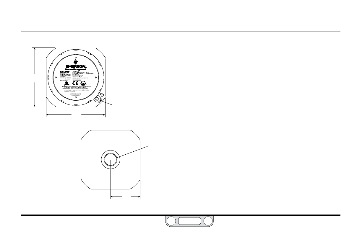
ER5000
Dimensions – Top and Bottom View
3.72
[94.5]
ER5000 Series
Electropneumatic Controller
3.72
[94.5]
Bottom View
Top View
Contact the factor y for dimensions an d specicatio ns
of model s ER5020, ER5040, ER5100 and ER 5110.
Refer to th e ER5000 Series Part Numbering System.
All dimensions are called out in
inches [millimeters]
Outlet Port
1/2 SAE (3/4-16 UNF)
1.86
[47.2]
www.emerson.com/tescom
Page 18

ER5000 Series — 18Features and Specications
BACK
DO NOT REMOVE
4.09
[103.8]
1/8" NPTF Plug
Not Used
.98
[24.9]
1/2-14 NPTF
Conduit
Connection for
USB Wiring
ER5050 Hazardous Location Model
Contact the factor y for dimensions an d specicatio ns
of model s ER5020, ER5040, ER5100 and ER 5110.
Refer to th e ER5000 Series Part Numbering System.
Gauge Port
1/8–27 NPTF
.43
[11.0]
.54 [13.77] .54 [13.77]
Dimensions – Side Views
External Ground
Atmospheric Reference
for Internal Sensor
CAUTION
Removal of ANY of the 1/8" NPTF
plugs called out on this page, other
than the Gauge Port plug, will
invalidate the Hazardous Location
certification for the ER5050.
1/2-14 NPTF
Conduit
Connection for
Internal Wiring
All dimensions are called out in
inches [millimeters]
Inlet Port
1/8–27 NPTF
.75
[19.0]
.93
[23.7]
.75 [19.0] (4x)
.93
[23.7]
Exhaust Port
1/8–27 NPTF
.83
1/8" NPTF Plug – Not Used
DO NOT REMOVE
[22.0]
Mounting
#10-32 UNF
.50 FULL THREAD
[M5 X 0.8
12.7 FULL THREAD]
(4 Places)
1/8" NPTF Plug
Not Used
DO NOT REMOVE
Holes
.20
[5.1]
www.emerson.com/tescom
Page 19
ER5000 Series — 19Features and Specications
BACK
ER5050 Hazardous Location Model
Dimensions – Top and Bottom View
3.72
[94.5]
3.72
[94.5]
Bottom View
Top View
Cover Lock Screw
1.86
[47.2]
Contact the factor y for dimensions an d specicatio ns
of model s ER5020, ER5040, ER5100 and ER 5110.
Refer to th e ER5000 Series Part Numbering System.
All dimensions are called out in
inches [millimeters]
Outlet Port
1/2 SAE (3/4-16 UNF)
www.emerson.com/tescom
Page 20

ER5000 Series — 20Features and Specications
NOTENOTE
BACK
ER 5000 Specifications
Contact the factor y for dimensions and specications of models ER5020, ER5040, ER5100 and ER5110. Refer to the ER5000 Series Part Numbering System.
Enclosure
Type 4X, IP66. If the two 1/2-14 NPTF ports are unused, properly
seal with a plug.
CE Approved Wiring Instructions
Use shielded, twisted pair cable.
Weight
3.1 lbs / 1.4 kg
Media
Supply pressure must be clean, dry inert gas or instrument grade
air that meets the requirements of ISA Standard 7.0.01. Use of an
in-line lter that meets the requirements of ISA standard 7.0.01
and is less than 40 microns and as small as 10 microns, is highly
recommended to prevent damage to the solenoid valves. Moisture
should be kept to a minimum.
Ports
Conduit: 1/2" NPTF
Pneumatic: 1/8" NPTF — Inlet, Exhaust and Gauge Ports
1/2" SAE — Controlled Outlet Port
www.emerson.com/tescom
Power Requirement
Voltage: 24V DC (22V DC to 28V DC)
Current: 340 mA max, 180 mA nominal
Environment
Temperature: -30°C to 75°C (dry Nitrogen supply gas)
Pressure: 28" to 32
Humidity: To 100% R.H. (non-condensing) @ 0°C to 75°C.
Inlet Pressure
Minimum: Outlet pressure + 1 psig
Maximum: 120 psig / 8.2 bar
Typical: 110 psig / 7.5 bar
Sensor Update Rate
25ms (rate of sensor reading and processing task)
USB Communication Interface
USB: 2.0
Maximum cable length: 15 ft / 4.5 m
Connector: Mini-B
5°C to 75°C (shop air)
" Hg / 71 mm to 762 mm Hg
Response time is affected by input pressure.
Page 21

ER5000 Series — 21Features and Specications
NOTENOTE
NOTENOTE
BACK
ER 5000 Specifications (cont.)
RS485 Communication Interface
Networking: Up to 32 controllers on one network
Maximum cable length: 4000 ft / 1219 m
Baud rate: 9600
Flow Rate
Cv: 0.01
The ow rate can be increased using a booster regulator.
Accuracy
Room temp: 0.1% of span maximum
Response Time
Rise Time: 257ms — 10 psig to 90 psig / 0.7 bar to 6.2 bar
Fall Time: 552ms — 90 psig to 10 psig / 6.2 bar to 0.7 bar
Step response into dead-end system (1 cubic inch volume).
External Analog Input Impedance
4–20 mA: 250Ω
1–5V: 220KΩ — single input pin to ground
0–10V: 100K Ω
www.emerson.com/tescom
1.7MΩ — differential input
Digital Inputs
Voltage Range/Input Impedance:
4–20 mA: 250Ω
1–5V: 220KΩ — single input pin to ground
1.7MΩ — differential input
0–10V: 100K Ω
Digital Outputs
Current: 50 mA continuous, 100 mA instantaneous
Voltage: 5V to 28V
Type: Open collector, grounded emitter
Analog Output
4–20 mA: Better than 0.5% accuracy;
loads from 50Ω to 1000Ω
0–10V DC: Better than 0.5% accuracy;
loads no less than 5000Ω
Page 22

ER5000 Series — 22Features and Specications
NOTENOTE
BACK
Hazardous Location Model (ER5050) Specifications
Certifications
Refer to Hazardous Locations Special Requirements and Certication
for the ER5050 for a complete list of hazardous location certications.
Enclosure
Type 4X/IP66. If the two 1/2-14 NPTF ports are unused, properly
seal with a metal plug.
CE Approved Wiring Instructions
Use shielded, twisted pair cable. Use rigid metal conduit to
enclose the wiring entering the ER5050 when required per local
electrical code.
Weight
2.6 lbs / 1.2 kg
Media
Supply pressure must be clean, dry inert gas or instrument grade
air that meets the requirements of ISA Standard 7.0.01. Use of
an in-line lter that meets the requirements of ISA standard
7.0.01 and is less than 40 microns and as small as 10 microns, is
highly recommended to prevent damage to the solenoid valves.
Moisture should be kept to a minimum.
www.emerson.com/tescom
Ports
Conduit: 1/2" NPTF
Pneumatic: 1/8" NPTF — Inlet, Exhaust and Gauge Ports
Power Requirement
Voltage: 24V DC (22V DC to 28V DC)
Current: 340 mA max, 180 mA nominal
Environment
Temperature: -20°C to 60°C (dry Nitrogen supply gas)
Pressure: 28" to 32
Humidity: To 100% R.H. (non-condensing) @ 0°C to 60°C.
Inlet Pressure
Minimum: Outlet pressure + 1 psig
Maximum: 110 psig / 7.5 bar
Typical: 110 psig / 7.5 bar
Sensor Update Rate
25ms (rate of sensor reading and processing task)
1/2" SAE — Controlled Outlet Port
5°C to 60°C (shop air)
" Hg / 71 mm to 762 mm Hg
Response time is affected by input pressure.
Page 23

ER5000 Series — 23Features and Specications
NOTENOTE
NOTENOTE
NOTENOTE
BACK
Hazardous Location Model (ER5050) Specifications (cont.)
USB Communication Interface
USB: 2.0
Maximum cable length: 15 ft / 4.5 m
Connector: Mini-B
Due to var ying hazardous location wiring requirements, a USB
cable is not included with the ER5050.
RS485 Communication Interface
Networking: Up to 32 controllers on one network
Maximum cable length: 4000 ft / 1219 m
Baud rate: 9600
Flow Rate
Cv: 0.01
The ow rate can be increased using a booster regulator.
Accuracy
Room temp: 0.1% of span maximum
Response Time
Rise Time: 257ms — 10 psig to 90 psig / 0.7 bar to 6.2 bar
Fall Time: 552ms — 90 psig to 10 psig / 6.2 bar to 0.7 bar
Step response into dead-end system (1 cubic inch volume).
www.emerson.com/tescom
External Analog Input Impedance
4–20 mA: 250Ω
1–5V: 220KΩ — single input pin to ground
1.7MΩ — differential input
0–10V: 100K Ω
Digital Inputs
Voltage Range/Input Impedance:
4–20 mA: 250Ω
1–5V: 220KΩ — single input pin to ground
1.7MΩ — differential input
0–10V: 100K Ω
Digital Outputs
Current: 50 mA continuous, 100 mA instantaneous
Voltage: 5V to 28V
Type: Open collector, grounded emitter
Analog Output
4–20 mA: Better than 0.5% accuracy;
loads from 50Ω to 1000Ω
0–10V DC: Better than 0.5% accuracy;
loads no less than 5000Ω
Page 24

ER5000 Series — 24Features and Specications
BACK
Accessories
Part # Description
80129 1/8" NPTF male tube connector
82575-25
82575-50
82919
82948
85061
85121
ERSA04539 20-wire, shielded, twisted pair cable assembly — 24" / 61 cm Included with “F” model ER5000s
85138-X 12-wire, shielded, twisted pair cable assembly — 5, 10, 20, 50 and 100 ft / 1.5, 3, 6, 15 and 30 m options
ERSA04539-X 20-wire, shielded, twisted pair cable assembly — 5, 10 and 20 ft / 1.5, 3 and 6 m options
85145 Filter kit
ERAA03458-02 Adaptor tting 1/2" SAE x 1/8" NPTF — mates ER5000 to most TESCOM™ air actuated regulators Included with all standard ER5000s
ERAA03458-04 1/2" SAE X 1/4" NPTF
ERAA03409 USB Cable with Mini-B connector Included with all standard ER5000s NOT for use with ER5050s
ERAA05146 MTA Connector Replacement Kit
250 mA / 24V DC power supply — input voltage 120V AC, 60 Hz
500 mA / 24V DC power supply — input voltage 120V AC, 60 Hz
Potentiometer with digital display
USB to RS485 converter
RS232 to RS485 converter
12-wire, shielded, twisted pair cable assembly — 24" / 61 cm Included with all standard ER5000s
www.emerson.com/tescom
Page 25

What’S neW
BACK
www.emerson.com/tescom
25
Page 26

ER5000 — 26What’s New
BACK
New Features
• Built-in USB connectivity
• Improved resolution for data acquisition with 16-bit A/D
converter
• For “F” model ER5000s, single 20-wire cable replaces separate
12-wire and 8-wire cables
• Suspend Control, a new operational mode available on
“F” models, gives you the ability to lock output at a stable
pressure over an extended period of time for operations, such
as sensor calibration, where system stability is critical.
• The
ERTune™
advantage of the Windows graphic user interface, with a
single, unied operating environment and quick, tab-based
access to all functions. Other enhancements include:
> Setup Wizard and COM Port Search speed up installation.
> The Tuning Tab now features highly responsive sliders,
with optimal ranges for all congurable parameters clearly
displayed in the interface.
> Data acquisition can now be triggered automatically
by system events such as digital input detection or a
monitored variable reaching a target value.
program has been upgraded to take full
> Proles can now include up to 100 command segments. Loop
counts are now displayed in real time.
> For “F” model ER5000s, Proles can now include these new
commands:
Soak, which waits until feedback indicates a new setpoint
has been reached before initiating a Dwell.
If and Goto, which allow you to create complex branching
command sequences that respond to real-time operating
conditions and inputs.
> The Diagnostic Tools Tab now gives you one-click access to
tuning and troubleshooting recommendations.
> The Automated Solenoid Leak Test gives you a quick,
intuitive and accurate assessment of the controller’s
solenoid valves.
> Regulator Diaphragm Protection is a new feature that gives
an added layer of protection for applications where rapidly
changing ow demands put undue stress on the sensing
element of diaphragm sensed regulators, particularly those
with metal diaphragms.
www.emerson.com/tescom
Page 27

ER5000 — 27What’s New
BACK
Replacing an ER3000 with an ER5000
IMPORTANT!IMPORTANT!
WARNING
Safety standards are subject to continual revision. Investigate and apply
the most recent standards for Hazardous Locations for your area set by
ANSI, ISO and OSHA, as well as all electrical codes and fire and safety
standards, before replacing a controller in a hazardous location.
Click this link to view all Hazardous Location certifications and
specifications.
Wiring for the Standard Model ER5000
The wiring for the 12-pin MTA connector is the same for the
ER5000SI-1 as it was for the ER3000SI-1. An MTA connector
replacement kit is available to allow use of the existing installation
cable with the new ER5000.
Reference current Hazardous Location
standards when replacing a Hazardous Location
ER3000 with an ER5050.
Wiring for the “F” Model ER5000
For “F” model ER5000s, the 12-pin MTA connector and 8-pin
auxiliary MTA connector, which were previously fed by separate
cables, are now fed by a single 20-wire cable. All wires feeding the
8-pin connector are color striped to distinguish them visually from
the solid color wires feeding the 12-pin connector. Refer to
Figure 18 to see all wire colors and pin terminations.
The function of the green/white wire (J4 Pin 5), which was
previously the Analog Signal Ground, has changed: it now
activates the Suspend Control function, which closes both valves
and locks the controller at the current pressure. If your current
application makes use of this wire, refer to the Installation
Variations section for recommended wiring congurations.
For standard model ER5000s, there are two wires which act
as signal/board grounds: the black wire (J3 Pin 10) and the tan
wire (J3 Pin 12).
For “F” model ER5000s, the black/white wire (J4 Pin 6) also acts as
signal/board ground.
www.emerson.com/tescom
Page 28

ER5000 — 28What’s New
NOTENOTE
BACK
Using the ER5000 with ER3000 software
If you wish to continue using the Windows Tune or other software
that controlled your ER3000, you must install Jumper J9 to put
the ER5000 into ER3000 Mode (refer to Figure 19). The ER5000
uses a 16-bit A/D converter to translate analog input signals into
the digital language the microprocessor understands, while
the ER3000 uses a 12-bit converter. In order for the ER5000 to
correctly interpret the signals generated by a program written for
the ER3000, it must use a 12-bit scale.
Installing the ER3000 Mode Jumper will also turn off the new
Suspend Control feature, as well as the new Prole commands.
UI3000 or UI4000
The ER5000 is NOT compatible with either the UI3000 or
the UI4000.
www.emerson.com/tescom
Page 29

hoW It
BACK
W
www.emerson.com/tescom
orkS
29
Page 30

ER5000 — 30How It Works
BACK
The ER5000: How It Works
The ER5000 (Electronic Regulator 5000) is a microprocessor-based
PID (Proportional, Integral, Derivative) controller that brings precise
algorithmic pressure control to a wide range of applications.
It can be used as a standalone unit to control the pressure of clean,
dry inert gases from 0–100 psig / 0–6.9 bar or be connected to any
pneumatically actuated regulator or valve. Used with TESCOM™
regulators, the ER5000 provides distributed pressure control of
gases and liquids from vacuum to 30,000 psig / 2068 bar, with a Cv
of up to 12.
The ER5000 can be controlled from any PC via a direct USB or
RS485 connection. The ER5000 also accepts analog setpoint
signals from 4–20 mA, 1–5V or 0–10V analog sources, such as
from a PC or PLC D/A card. The ER5000 can be wired to allow for
multiple input/output congurations and daisychaining of up to 32
controllers within the same RS485 network.
The ER5000 senses pressure using either its internal sensor or an
external transducer (4–20 mA, 1–5V or 0–10V) placed within the
actual process line. You can operate the ER5000 in one of three
control modes:
• Internal Feedback, which uses only the internal sensor
• External Feedback, which uses only the external source;
• Cascade, which uses both internal and external sources in a
“loop within a loop” conguration.
During setup, you can download PID settings that have been
programmed by TESCOM to meet the needs of most commercial
applications. The included ERTune™ program provides an intuitive
interface to customize the performance parameters of the ER5000
by directly tuning the Proportional, Integral and Derivative values.
Using the ERTune™ program, you can create Proles, which guide
the ER5000 through command sequences that may include
multiple setpoint changes, precisely timed digital inputs and
outputs and modication of response characteristics and other
internal variables based on real-time operational conditions.
The ER5000 installs in just minutes, yet provides the precision,
dependability and exibility to meet the needs of the most
demanding user.
;
www.emerson.com/tescom
Page 31

ER5000 — 31How It Works
BACK
Understanding PID Controllers
PID Controllers allow mechanical systems to operate at a high
level of precision and dependability with only occasional oversight
by human operators. They can control virtually any measurable
physical property within the system, including pressure, ow,
temperature, position, speed, force, consistency, torque
and acceleration.
PID controllers operate in a continuous loop of monitoring and
response. The ER5000 performs one loop every 25 ms (milliseconds).
At the start of each loop, the controller reads the input from a sensor
within the system to nd the current level of a measured property
such as system pressure (the Feedback) and compares it to a preset
target value (the Setpoint).
If the two values match, a Zero Error is generated and no action is
taken. If the two values do not match, a positive or negative Error is
generated and the controller activates to correct the error.
When the error is the result of an unintended change in the
operating environment, the controller works to return the system
to its previous level. When the error is the result of a scheduled
change in the setpoint, the controller works to raise or lower the
system to the new target level.
In either case, the controller continues to act until setpoint and
feedback are equal. The controller then generates a zero error and
returns to its monitoring function. At this point, the system is said
to be in a Stable State.
The response of the PID controller, from error generation to
stable state, is shaped by a complex algorithm that incorporates
three independent but interrelated values (also referred to
as Ter ms).
• The Proportional (P) term is a function of the value of the
error generated during the current loop. With each loop,
the P value changes in direct proportion to the amount of
error. Proportional is largest when the error is rst detected
and grows progressively smaller as the controller brings the
system closer to setpoint.
• The Integral (I) term is a function of the combined values
of all errors generated while the system is in operation. The
I value continues to increase as long as the system is in error
and will only decrease when an error is recorded in the opposite
www.emerson.com/tescom
Page 32

ER5000 — 32How It Works
BACK
direction. Signicantly, Integral retains its value after the error
has been corrected. This is known as Integral Windup.
• The
Derivative
change. The D value decreases, then begins to dampen the other
values, as the controller brings the system closer to setpoint.
(D) term is a function of the current rate of
PID Controllers: Three Components Are Better Than One
Why three independent values? Consider this scenario:
• You are behind the wheel of a car that needs to turn through a
curve in the road.
• As the car enters the turn, you simply steer to match the
curve. At this point, you are a Proportional controller.
• As the car continues through the turn, however, peripheral
force pushes it outward. Matching the curve (Proportional
only) is no longer sufcient. You now nd it necessary to
oversteer (add Integral) to stay in the curve. Then a gust of
wind hits the side of the car; now you need to oversteer more
to compensate for both the wind and the peripheral force
(accumulated Integral).
• As the car passes the midpoint of the curve, the peripheral
force decreases and the wind dies down. Now the oversteer
(Proportional and accumulated Integral) threatens to put
the car into a skid. You respond by understeering (adding
Derivative) through the rest of the curve until you are back on
straight road.
• As you drive on, you remember the wind that hit at the most
inopportune moment, so you keep a close hand on the wheel
in case there is another gust (Integral windup).
Like the driver who knows when to follow the road, when to
oversteer and when to understeer, controllers that can combine
the effects of Proportional, Integral and Derivative have the
exibility to respond effectively to the widest range of application
requirements and environmental conditions.
Now consider the same curve with three different drivers.
• The rst driver spots a police car in the next lane. This driver’s
primary goal will be to stay squarely within the lane through
the whole length of the turn. This controller carefully balances
Proportional, Integral and Derivative.
www.emerson.com/tescom
Page 33

ER5000 — 33How It Works
BACK
• The second driver notices that there is a full cup of hot coffee
in the cup holder. This driver will take the curve as widely
and as slowly, as possible, because this driver’s primary goal
is to make sure the hot liquid does not spill. This controller
has lowered the Proportional and Integral and increased the
Derivative, to make the response as stable as possible, at the
expense of some speed and precision.
• The third driver is participating in a road race. This driver will
take the curve as tight and fast as possible, pushing the limits
right up to the point of spinning the car out of control. This
controller has maxed out the Proportional and Integral to get
the fastest response possible, then set Derivative just enough
to reestablish control at the end.
Three controllers, three different goals, three different responses
to the same change. By raising and lowering the relative amounts
of Proportional, Integral and Derivative (a process called Tuning
the controller) you can set up your ER5000 to meet the specic
response characteristics and work within the specic limitations,
of any system.
A Typical PID Control System
Figure 2 shows a simplied diagram of a typical PID
control system.
In this drawing, the dashed line represents the controller. The
setpoint (r) is sent from the internal board or an external source.
The feedback (y) is sent from internal or external sensors that
monitor the current state of the system. The controller reads
both values and subtracts the feedback signal from the setpoint.
Setpoint = r
Controller
Error = e
+-
Figure 2: Simplified PID Control System
Output
Feedback = y
System
Under
Control
www.emerson.com/tescom
Page 34

ER5000 — 34How It Works
BACK
If setpoint and feedback match, the controller generates a zero
error and does not activate.
If setpoint and feedback do not match, the controller generates
an error value (e), activates and sends an output to the system
to correct the error. For example, in the ER5000 the output is
directed to Solenoid Valves within the controller.
A positive error is generated when feedback is lower than setpoint.
The ER5000 responds to positive error by activating to increase
system pressure.
A negative error is generated when feedback is higher than
setpoint. The ER5000 responds to negative error by activating to
decrease system pressure.
The controller determines how much output to send by
summing two values:
• The Proportional term, which is the product of the generated
error and the constant Kp (the Proportional Constant).
• The Integral term, which is the product of the integral of all
accumulated errors and the constant Ki (the Integral Constant).
Control systems based on just the Proportional term or just
the Proportional and Integral terms, are known as a P and PI
congurations. The ER5000 can operate in a P or PI conguration
if this is appropriate for the application. The PID conguration,
which includes the Derivative term, offers the greatest level of
precision and exibility.
The Derivative term is often used to attenuate the feedback before
it is compared to setpoint. It is shown this way in Figure 2. The
Derivative of the feedback is multiplied by the constant Kd (the
Derivative Constant) and the resulting value is summed with
the feedback.
Because the Derivative is a function of the rate of change, its
primary function is to act as a damper and suppress oscillations as
the system approaches setpoint.
www.emerson.com/tescom
Page 35

ER5000 — 35How It Works
BACK
Tuning a PID Controller
Tuning a controller is the process of selecting the optimal
Kp, Ki and Kd settings to yield the best response. The “best”
response depends on what is most important for the application
and usually entails a compromise between speed of response
and stability.
Your ER5000 is pre-tuned at the factory and a default PID setting
congured by TESCOM™ to match your TESCOM regulator can
be downloaded to the controller during setup. For many users,
the default tuning will provide effective system control right
out of the box. Others will nd that the specic requirements
of their application or operating environment call for some
additional manual tuning, using the ERTune
optimal performance.
The mathematics of PID algorithms are complex and beyond the
scope of this manual. Understanding the response characteristics of
your system will inevitably involve trial and error.
Nonetheless, PID tuning can also be understood in basic functional
terms. There are predictable effects, both positive and negative,
to watch for as settings are increased or decreased. If necessar y,
™
program, to achieve
default settings can be restored with the click of a button (see To
reset the ER5000 to its default PID settings).
Using a few rules of thumb and the real-time visual feedback
™
provided by the ERTune
program, all operators, regardless of
experience, can achieve positive results through manual tuning of
their controllers.
Rules of Thumb for PID Tuning
• The Proportional setting controls the overall response curve
of the controller. It is set rst. Integral and Derivative are
added to ne tune the response.
• The Integral setting accelerates the response, particularly
as the system approaches setpoint and the Proportional
decreases. It is primarily used to minimize a condition known
as Steady State Error or Offset, where the system settles into
a stable state without reaching the targeted setpoint. The
Integral also remains “charged up” with Integral windup after
an error has been corrected.
• The Derivative setting dampens the response and is used to
prevent the system from overcorrecting. Generally set next
after Proportional.
www.emerson.com/tescom
Page 36
ER5000 — 36How It Works
BACK
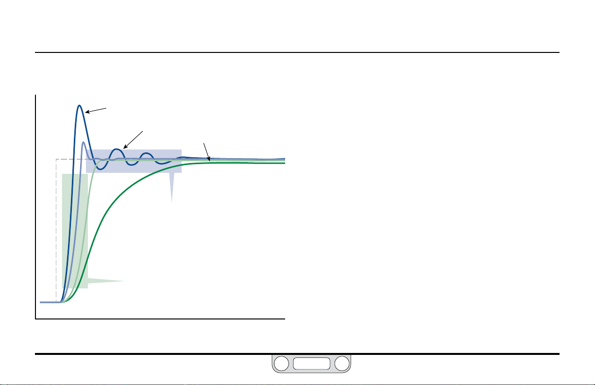
Figure 3 shows four typical response curves to a step
(instantaneous) change in setpoint.
A
Overshoot
Ringing
B
P
R
E
S
S
U
R
E
Figure 3: Typical Response Curves to Programmed Setpoint Change
C
D
Settling Time
Rise Time (10%–90%)
TIME
Offset
The controller in Curve A responds with a Rise Time that is short
and sharp. It also overcorrects (Overshoots) the error and oscillates
around the new setpoint, a condition known as Ringing. There is a
prolonged Settling Time before the system reaches its new stable
state. The overall response is quick but unstable.
The controller in Curve D has a long, gradual rise time and ends
up in Steady State Error, settling into a stable state that is slightly
below the new setpoint.
Curve A demonstrates the unwanted effects of a fast, but also
unstable, response. Tuning this controller will entail lowering the
Proportional setting and perhaps the Integral setting as well.
Alternatively, increasing the Derivative will help to stabilize the
response. Curve D demonstrates the unwanted effects of a
stable, but overly slow, response. Tuning this controller will entail
increasing Proportional. Integral also should be increased to
eliminate the offset. Derivative should be checked to see if it is
overdamping the response.
The controllers in Curves B and C have been tuned to achieve a
balance between speed and stability. Curve B allows a small amount
of overshoot and ringing in exchange for the fastest rise time
possible, with a settling time that is short and stable. Curve C is
www.emerson.com/tescom
Page 37

ER5000 — 37How It Works
BACK
“critically damped,” with just enough Derivative added to eliminate
overshoot completely. Both tunings have no offset. Curve B
would be an optimal tuning for an application which can tolerate
overshoot, Curve C for one which cannot.
To restate the rules of thumb for each component:
Proportional (P):
• Higher settings result in shorter rise times and faster response.
• Higher settings also make the response less stable, with
overshoot and ringing. Overshoot may tax the physical
limitations of the system.
• Lower settings result in slower response.
Integral (I):
• Higher settings accelerate the response.
• Higher settings also increase instability.
• Lower settings result in a less responsive controller.
• Because Integral windup continues to push the response even
after the system has reached stable state, higher Integral
settings can eliminate offset.
• Windup can delay the controller’s response to new errors, as
accumulated errors must “spool out” before new errors can
begin “charging up” Integral. The ER5000 features exclusive
Integral Limits to control positive and negative windup, allowing
you to use higher Integral settings.
• The Integral of small errors can, over time, accumulate to the
point of causing unwanted activation of the controller. The
ER5000 features an exclusive lter called Integral Deadband
to mitigate this effect.
Derivative (D):
• Higher settings correct overshoot and ringing.
• Higher settings also decrease settling time and increase
system stability.
• Higher settings may overdamp the system, causing a slow
rise time.
• Paradoxically, higher Derivative settings can make some
systems unstable by increasing sensitivity to transient
changes (noise) in the operating environment. This sensitivity
can decrease the operational lifespan of the ER5000’s
solenoid valves due to frequent activation.
www.emerson.com/tescom
Page 38
ER5000 — 38How It Works
BACK
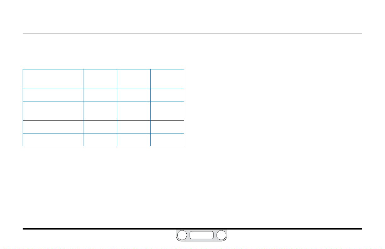
Table 1 gives a summary of the rules of thumb for Proportional,
Integral and Derivative.
Table 1: Effect of P, I and D Increases on Response Curve of Controller
Increased
P Value
Rise Time Faster Faster Slower
Instability
(Overshoot/Ringing)
Settling Time Varies Longer Shorter
Offset Less Eliminate Varies
* Exces s D Value can, h owever, result in mor e instabilit y rather than less. Refer to
the restatem ent of the rules of thumb for D erivative on p age 37.
More More Less*
Increased
I Value
Increased
D Value
The ERTune™ program gives you a rich visual environment and
precise, intuitive controls for tuning the ER5000. Refer to The
Tuning Tab: Controls and Functions for Tuning the ER5000
for a detailed explanation of the program’s capabilities and
features, as well as tips and techniques to achieve optimal
system performance.
Every system has unique characteristics, every operational
environment presents unique challenges and every application
has unique requirements. Optimal tuning will invariably involve
both trial and error and compromise. Fast rise time usually comes
at the expense of increased instability. Minimizing overshoot may
result in response lag or offset. Eliminating offset may introduce
unwanted windup. It is important to know your priorities and
understand the trade-offs.
www.emerson.com/tescom
Page 39

ER5000 — 39Typical Application
BACK
The ER5000: Typical Application
WARNING
(Non-Hazardous Location)
Investigate and apply the most recent standards for Hazardous Locations
for your area set by ANSI, ISO and OSHA, as well as all electrical codes and
fire and safety standards, to determine if your application will require
a Hazardous Location model. If your application requires a Hazardous
Location model (ER5050), refer to
Installing a Hazardous Location
Model (ER5050) on p age 110.
Controlling System Pressure
In a typical application, the Outlet Port of the ER5000 connects
to the top of a Dome Loaded or Air Actuated pressure reducing
Regulator, usually through the included 1/2" SAE x 1/8" NPTF
adaptor. This is shown in Figure 4.
Supply Pressure of up to 120 psig / 8.2 bar, with 110 psig / 7.5 bar
being typical, is provided to the ER5000 by an external source.
The ER5000 increases Pilot Pressure to the air actuator of the
regulator by opening the Pulse Width Modulation (PWM) solenoid
valve at the Inlet Port and reduces pilot pressure by opening the
PWM solenoid valve at the Exhaust Port. Normally, the exhaust
vents to atmosphere.
The controller, congured in External Feedback mode, senses
System Pressure through input from a transducer mounted
downstream in the Process Line.
USB
Connection
ER5000 Supply
Pressure
110 psig / 7.5 bar
Adaptor
Regulator
Inlet Pressure
Figure 4: Typical ER5000 Application
Controller, with adaptor, is mounted to an air actuated regulator. Feedback is from the external
transducer. Setpoint is from a Prole downloaded from the PC through the USB connection.
External
Transducer
Outlet Pressure
To Process
PC
www.emerson.com/tescom
Page 40

ER5000 — 40Typical Application
BACK
Every 25 milliseconds, the controller reads the feedback and
compares it to the setpoint, which it receives from an external
source or from a Prole in its onboard memory.
than setpoint, the ER5000 activates the inlet valve, allowing Pilot
Pressure to ow into the actuator of the regulator. This causes the
main valve of the regulator to open up, resulting in an increase in
downstream System Pressure. The ER5000 will continue to send
pilot pressure into the air actuator of the regulator until feedback
and setpoint are equal. At that point, the inlet valve closes,
stabilizing the system at that pressure.
If feedback is higher than setpoint, the ER5000 activates the
exhaust valve, releasing pilot pressure from the regulator. The
decrease in pilot pressure causes the main valve of the regulator
to close up and also causes the regulator vent to open, exhausting
excess system pressure (if your application uses a non-venting
regulator, refer to page 41). The result is a decrease in
downstream system pressure. The ER5000 will continue to exhaust
pilot pressure until the feedback signal is equal to the setpoint.
At that point, the exhaust valve closes, stabilizing the system at
that pressure.
If feedback is lower
Supply
Pressure
110 psig /
7.5 bar
Air Actuator
Regulator
Inlet
Pressure
ER5000
Inlet Port
Vent Valve
Inlet
Valve
Pilot
Pressure To
Air Actuator
Pilot
Pressure From
Air Actuator
Captured Vent
Exhaust
Valve
ER5000 Outlet Port
and Adaptor
Main Valve
exhausts excess pressure
ER5000
Exhaust Port
Pressure Vents
to Atmosphere
Regulator
Outlet
Pressure
USB Connection
Setpoint
Source can be either a digital
signal provided over USB or
RS485, an analog signal or a
Prole stored in onboard memory.
Feedback
For optimal system
performance, an accuracy of
0.1% or better is required. A
less accurate transducer can
be used, but doing so will
degrade the accuracy of the
overall system.
Figure 5: Internal Operation of the ER5000 Controller
PC
www.emerson.com/tescom
Page 41

ER5000 — 41Typical Application
BACK
A Note Concerning Non-Venting Regulators in Closed Loop Applications
Non-venting regulators, which do not feature a regulator vent to
exhaust excess system pressure, pose a particular challenge in
closed loop applications when the downstream ow is blocked.
When downstream ow stops suddenly, for example when a
downstream valve is closed, feedback rises rapidly. The regulator
responds by closing its main valve. However, due to Lock-up in the
regulator, a small amount of excess pressure escapes through the
main valve before it achieves a completely tight seal.
In venting regulators, this excess downstream pressure is
exhausted by the regulator vent, allowing the system to return
to stable state. In non-venting regulators, this excess pressure is
trapped in the downstream pipe.
The PID controller senses the rise in feedback and activates to
lower system pressure. But the regulator cannot respond, since it
cannot vent. Because the excess system pressure is trapped, the
error will not change. The controller could continue to respond
until the pilot pressure is completely vented through the exhaust
valve. This can create two different undesirable conditions:
• If the regulator is a metal diaphragm sensed regulator, the
differential between the high downstream pressure beneath
the diaphragm and the low (or even zero) pilot pressure above
the diaphragm can critically stress the diaphragm.
• Regardless of regulator type, if the downstream ow suddenly
restarts, the PID controller’s response will be delayed,
because it will need to completely rell the regulator’s dome
or air actuator cavity.
When the Diaphragm Protection feature of the ER5000 is
activated, the controller responds to error only up to a set
percentage of the original pilot pressure, then stops. This allows
the controller and regulator to be reset quickly once system ow
has been restored and minimizes pressure differentials that can
effect regulator components.
The Regulator Diaphragm Protection feature is strongly
recommended for applications using metal diaphragm sensed
regulators. It provides a control benet for applications using non-
venting regulators. It is not required for applications using venting
regulators or piston sensed regulators.
Refer to The Diaphragm Protection Panel to learn more about
this feature.
www.emerson.com/tescom
Page 42

ER5000 — 42Typical Application
BACK
Monitoring System Control Limits
The ER5000 also can be congured to monitor the system and
respond if user-specied limits are exceeded. This function is
deactivated by default and can be activated using controls in the
ERTune™ program. Refer to The Control Limits Panel section for
more information.
This feature provides added security in the event of a system
failure such as broken transducer wiring, lack of supply pressure or
pipe ruptures.
CAUTION
The Control Limits feature provides an additional level of system
monitoring. Activation indicates a potential problem, but will not, by
itself, prevent problems from occurring. It should not be considered
to be a safet y mechanism, nor is it intended to be a safety feature or
pressure limiting device.
When an ER5000 congured to monitor Control Limits detects a signal
indicating that a limit has been exceeded, it activates its solenoid valves
to reach one of three Control Limit Conditions:
• Inlet Closed/Exhaust Closed
• Inlet Closed/Exhaust Open
• Inlet Open/Exhaust Closed.
The default Condition is Inlet Closed/Exhaust Open, which
ensures that a pressure reducing system will be vented if a limit is
exceeded. If your application uses a non-venting regulator, refer
to A Note Concerning Non-Venting Regulators in Closed Loop
Applications if you intend to use the ER5000 in this condition.
Minimum and maximum limits can be monitored for any or all of
these variables:
• Analog Setpoint
• Internal Sensor
• External Sensor
• Inner Error
• Outer Error.
www.emerson.com/tescom
Page 43

ER5000 — 43Control Modes
NOTENOTE
BACK
The ER5000: Control Modes
Internal Feedback Mode
Internal Feedback Mode uses the ER5000’s internal
sensor to monitor the pressure within the controller’s 0–100 psig /
0–6.9 bar internal pressure range. This mode is typically used
when the ER5000 is used as a standalone unit or when open-loop
control of a regulator is desired.
External Feedback Mode
External Feedback Mode uses a user-supplied external transducer
to monitor the system pressure. The transducer is installed in the
process line and provides direct feedback to the ER5000. This mode
is typically used when the ER5000 acts as the pilot regulator for a
regulator or valve.
An external transducer may also be installed in the ER5000’s
pressure line when the ER5000 is used as a standalone unit. This
may be preferable to Internal Feedback mode when:
• The application requires precise control within a small pressure
range. For example, the ER5000 will respond more efciently
to a 5% change in a 0–10 psig / 0–0.7 bar range than to a 0.5%
change in its full 0–100 psig / 0–6.9 bar range.
• There is a need to monitor downstream pressure. For example,
if the output passes through a length of pipe to a vessel and it is
expected that there will be pressure drops in the pipe, an external
sensor installed at the vessel will provide a more responsive
feedback signal than the controller’s internal sensor.
Cascade Mode
Cascade Mode implements one PID loop within another PID loop.
The inner loop uses the controller’s internal sensor and the outer
loop uses an external sensor. This mode of operation creates more
stability, but slows down the response of the system.
For proper operation in Cascade Mode, the following
recommended defaults for the Integral Limits of the external feedback
loop (also known as the outer loop) are downloaded into the controller
during setup: Maximum: 32767; Minimum: 0. These settings are optimal
for most applications.
Refer to The Cascade Tuning Tips and The Integral Limits
Controllers for more information on these settings.
www.emerson.com/tescom
Page 44

GloSSary
BACK
of termS
www.emerson.com/tescom
44
Page 45

ER5000 — 45Glossary of Terms
BACK
Terms Relating to PID Controllers and Controller Tuning
D/A Cards
Acronym for Digital To Analog Card. Used in PCs and PLCs to
generate analog signals.
Daisychain
Multiple ER5000s wired together in sequence that communicate
with a single, central PC on the same RS485 network. Each
controller within the chain must be given a unique Node Address,
which is done using the ERTune™ program.
Deadband
See Integral Deadband and Pulse Deadband.
Derivative
The component of a controller’s response that is based on the rate
of change within the system. Generally acts to dampen the effect of
Proportional and Integral and to increase system stability.
Error
The result that is generated when Feedback is subtracted from
Setpoint. A zero error results in no activation. A non-zero error
www.emerson.com/tescom
causes the ER5000 to activate until the error is corrected. A positive
error causes the ER5000 to increase system pressure and a negative
error causes the ER5000 to decrease system pressure.
Feedback
The input sent from an internal or external sensor that indicates
the current level of the process a PID controller manages. The
controller subtracts feedback from Setpoint, generating an Error
and any non-zero error activates the controller.
Hazardous Location
The Hazardous locations are areas where ammable liquids, gases
or vapors or combustible dusts exist in sufcient quantities to
produce an explosion or re. Specially designed equipment and
special installation techniques must be used in these applications,
because an electric current is present during normal operation
of the controller, so there is the potential to generate a spark. If
your application environment meets the standard for a Hazardous
Location, you MUST use model ER5050 and follow the installation
specications outlined on page 110 in order to provide a safe
operating environment.
Page 46

ER5000 — 46Glossary of Terms
BACK
Integral
The component of a controller’s response that is based on
accumulated error within the system. Continues to accumulate as
long as there is a non-zero Error and retains its value until errors
are generated in the opposite direction. Accelerates the effect of
Proportional. Often referred to as “reset,” because its continually
increasing value effectively “resets” the value of Setpoint within
the controller’s computations above or below its actual level.
This allows PID controllers to eliminate Offset. The retained
Integral value, also known as Integral Windup, must be carefully
controlled to prevent response lag.
Integral Deadband
Stop-band lter that deactivates Integral within a set percentage
range around Setpoint. Prevents small, transient errors from
accumulating to a level that activates the controller. Accessed
through The Tuning Tab in the ERTune™ program.
Integral Windup
Amount of accumulated value that is retained by Integral after error
has been corrected. Excess windup can cause the controller to lag in
response to new Errors. Proper Tuning prevents windup by setting
limits on accumulated value through the Integral Limits.
Integral Limits
Pair of lters which limit the amount of Integral Windup that can
accumulate during Error correction. Maximum limit is set for
positive errors (Setpoint minus Feedback is positive). Minimum
limit is set for negative errors (setpoint minus feedback is
negative). Accessed through The Tuning Tab in the ERTune™
program. Allow for high Integral settings without unwanted
effects. Generally set to the smallest value necessary to
eliminate Offset.
Node Address
Virtual address of the ER5000 within a network. Each controller
is assigned a default address of 250 at the factory. When multiple
ER5000s are in a Daisychain within the same RS485 network,
each controller must be assigned a unique address so that the PC
can locate and communicate independently with each controller.
The Node Address can be changed using The Congure Tab in the
ERTune™ program.
Noise
Short, transient changes to the system that are generally too
small to require activation of the PID Controller. A Derivative
setting that is too high may make the controller overly reactive
www.emerson.com/tescom
Page 47

ER5000 — 47Glossary of Terms
BACK
to noise, at the expense of system stability and cycle life of the
ER5000’s solenoid valves.
Offset
Also known as Steady State Error: a condition of Proportionalonly response where the system reaches a stable state that is
slightly above or below the targeted Setpoint. Two aspects of
Proportional contribute to this effect: the inevitable mechanical
lag between generation of Error and the physical response of the
valves to the controller output and the fact that a response that
is a direct multiple of error will always fall short of 100% error
correction. Proper Tuning generally aims to eliminate offset by
adding Integral.
Open Collector
A common type of output for integrated circuits, where the
emitter of the transistor is connected to ground and the collector
of the transistor is connected to the output. Instead of outputting
a signal of a specic voltage or current, the output acts as either
an open circuit or a connection to ground. Open collector circuits
are used in many systems, such as to interface devices that have
different operating voltage levels or to connect multiple open
collector devices to a single line.
Overshoot
Overcorrection due to a Proportional or Integral setting that is
too high. Must be carefully controlled to keep response within the
operational parameters of the system. Proper Tuning generally
aims to minimize overshoot.
PC
Acronym for Personal Computer.
PID Controller
An automated control device that monitors a property of a
mechanical system in a continual loop and uses an algorithm
incorporating a Proportional, Integral and Derivative component
to correct Error and maintain system stability.
Pilot Pressure
The pressure applied to the top of a Dome Loaded or Air Actuated
Regulator that controls the Control Pressure of that regulator.
The ER5000 is most commonly used to control pilot pressure to a
dome loaded or air actuated regulator.
PLC
Acronym for Programmable Logic Controller.
www.emerson.com/tescom
Page 48

ER5000 — 48Glossary of Terms
BACK
Pressure Reducing Regulator
Regulator that reduces high-pressure supplies of gas or liquid to a
safe or usable level for an application.
Process Line
Area within a system where the activity takes place that is
controlled by the PID controller, such as the pressure within a
pipeline or vessel. External sensors send Feedback from the process
line to the controller.
Profile
Command sequence, created using The Prole Builder Panel
in the ERTune™ program, which can be downloaded to the
control board of the ER5000. Guides the ER5000 through a
set of actions that may include multiple Setpoint changes,
modication of response characteristics and other internal
Variables based on real-time operational conditions and, in “F”
model controllers, precisely timed digital inputs and outputs.
Proles may also be saved to a PC for future use.
Proportional
The component of a controller’s response that is a direct function
of the Error generated by the current level of Feedback from
the system.
Pulse Deadband
Stop-band lter that deactivates Pulse Mode within a set
percentage range around Setpoint.
Pulse Mode
Refer to The Pulse Mode Panel for a complete description of
this feature.
Pulse Width Modulation (PWM)
Method of controlling a device such as a mechanical valve using
the control signal from a digital microprocessor (which can only
be ON or OFF) by varying the amount of time during a given cycle
when the ON signal is being sent.
The proportion of time that the signal is ON, from 0% to 100% of
the cycle, is known as the “duty cycle”. Because of mechanical lag
(the amount of time it takes for the valve to physically respond
to the instantaneous change in signal), the valve is constantly
“catching up” with the ON/OFF control signal in direct proportion
to the duty cycle. For example, a duty cycle of 75% results in a valve
that is approximately three-quarters open during that cycle.
The inlet and exhaust valves in the ER5000 are both PWM driven,
with a cycle time of 25 milliseconds.
www.emerson.com/tescom
Page 49

ER5000 — 49Glossary of Terms
BACK
Regulator
Mechanical valve that dynamically controls the pressure of liquid
or gas in a process line by opening or closing in response to
activation of an internal control element. Works to ensure that
the supplied pressure matches the demand of the system.
Ringing
Oscillation around a Setpoint, due to a Proportional or Integral
setting that is too high or a Derivative setting that is too low.
Proper Tuning generally aims to minimize ringing.
Rise Time
Time required for feedback to reach a new Setpoint or a certain
percentage of that setpoint, following a Step Change. TESCOM™
uses the ISA standard, which species rise time as the time it takes
to travel from 10% to 90% of the new setpoint. Proper Tuning aims
to minimize rise time without inducing Overshoot or Ringing.
Segment
One command line within a Prole.
Setpoint
The value that a PID Controller works to maintain within the system
it controls. The setpoint may remain at one level or change over
time, depending on the requirements of the system. A well tuned
controller will maintain a Stable State at setpoint and implement
setpoint changes quickly and accurately. The ER5000 requires a
setpoint signal in order to function. This signal can come from an
external source such as a PC or PLC or from a Prole.
Settling Time
Time required for a system to reach a stable state once it has
reached a new setpoint. Proper Tuning generally aims to minimize
Settling Time.
Solenoid Valve
An electromechanical valve controlled by electrical current
through a coil. The ER5000 valves are Pulse Width Modulation
(PWM) driven mechanical valves that open and close in
direct proportion to the output signal from the controller’s
microprocessor. Positive output activates the inlet valve,
increasing pressure and negative output activates the exhaust
valve, decreasing pressure.
www.emerson.com/tescom
Page 50

ER5000 — 50Glossary of Terms
BACK
Stable State
Any time that a PID Controller generates a zero Error for more
than one loop of monitoring and response. Proper Tuning aims to
nd a correct balance between stability and speed of response.
Steady State Error
See Offset.
Step Change
Change in Setpoint that occurs within a single loop of monitoring
and response for a PID controller.
Supply Pressure
Pressure applied to the inlet of the ER5000 from an external
source. Sent by the ER5000 as Pilot Pressure to pilot a Dome
Loaded or Air Actuated Regulator.
System Pressure
The pressure of the gas or liquid in a Process Line that is controlled
by the Regulator, which is controlled in turn by the Pilot Pressure
from the PID Controller. There are two components to system
pressure: the inlet pressure (upstream pressure), which is the
pressure level of the gas or liquid in the process line at the point
where it enters the regulator and the outlet pressure (downstream
pressure), which is the pressure level of the gas or liquid as it exits
the regulator. For a Pressure Reducing Regulator, the inlet pressure
must be higher than the outlet pressure.
Ter m
Used alternatively with value when referring to Proportional,
Integral and Derivative.
Transducer
Commonly used term for an external sensing device that provides
a feedback signal.
www.emerson.com/tescom
Page 51

ER5000 — 51Glossary of Terms
BACK
Tuning
The process of setting values for the Proportional, Integral
and Derivative constants within the PID Controller to achieve
optimal performance.
Variable
Any conguration setting for the ER5000, such as the
Proportional, Integral and Derivative constants, the setpoint
value, the Control Mode or the Node Address. Refer to the Internal
Variables section for a complete list. Variable values can be
included in data collection and certain variables can be tracked
using The Plot Screen of the ERTune™ program.
www.emerson.com/tescom
Page 52

ER5000 — 52Glossary of Terms
BACK
Terms Relating to Regulators
Accuracy
The acceptable level of pressure variation for a Regulator under
steady state conditions within its control range. All physical and
mechanical processes have some level of variation.
Air Actuated
Also known as Air Loaded: one type of loading element for a
pressure Regulator. Utilizes low pressure gas as the Loading
Element (Loading Force), typically 0–80 psig / 0–5.5 bar. This
is a form of ratio loading: the regulator uses low Pilot Pressure
to regulate a Control Pressure that may be much higher (see
Ratio Actuator). The most common type of regulator used with
the ER5000, as it is the only type that can be used for control
pressures greater than 100 psig / 6.9 bar.
Captured Venting
Feature incorporated in some venting Regulators which provides
an additional port that can be connected to piping in order to safely
dispose of excess liquid or gas expelled by the regulator’s vent valve.
The vent por t should never be plugged. Not all venting regulators
have this feature. Refer to Venting Regulator.
Control Element
One of the three basic elements of a Regulator. Acts to reduce high
Inlet Pressure to a lower working pressure (Outlet Pressure). The
control element is sometimes called the main valve, valve stem
or poppet.
Control Pressure
The component of System Pressure that is the result of the
regulating action of the Regulator. Can be either the Outlet Pressure
or the Inlet Pressure, depending on the type of regulator. For a
pressure reducing regulator, the control pressure is the Outlet
pressure. For a back pressure regulator, the control pressure is the
Inlet pressure.
www.emerson.com/tescom
Page 53

ER5000 — 53Glossary of Terms
BACK
Creep
An increase in the Outlet Pressure following Lock-up. Usually seen as
a slow, gradual pressure increase. Indicates a regulator leak and calls
for the immediate removal of the regulator for service.
C
v
The ow coefcient: equal to the number of U.S. Gallons of
water at 60°F / 16°C that will ow through a valve, regulator or
restriction in one minute when the pressure differential between
inlet and outlet is one pound per square inch (1 psi). When gas is
used instead of liquid, the equation is modied to account for the
use of a compressible uid. For a regulator, Cv is determined when
the regulator is wide open and not regulating. When determining
actual performance during regulating conditions, use ow curves.
Decaying Inlet Characteristic
Also known as Supply Pressure Effect. The effect on the set
pressure of a regulator as a result of an Inlet Pressure change;
usually an increase in Outlet Pressure due to a decrease in
inlet pressure.
In pressure reducing regulators, outlet pressure is set when force
from the load element, which opens the main valve, is matched
by inlet pressure moving through the valve. If inlet pressure
decreases, for example when a supply cylinder starts to empty
and the inlet pressure it supplies starts to decrease, this tips the
balance in favor of the load element and opens the valve wider.
This allows more ow, which results in a higher output pressure
and the seemingly paradoxical fact that a decrease in inlet
pressure results in an increase in outlet pressure.
Two-stage regulator design or the use of PID controllers, can
prevent this characteristic.
Diaphragm
One of several t ypes of Sensing Element. A diaphragm is sensitive
in reacting to pressure changes. Common diaphragm materials are
Buna-N, Viton, Ethylene Propylene, 316 Stainless Steel and Elgiloy.
Dome Loaded
One type of Loading Element. Pilot Pressure enters the dome at a
pressure equal to the Outlet Pressure desired. Generally requires
some additional pressure to activate: refer to Negative Bias. Can be
used with the ER5000 for low Control Pressure applications.
www.emerson.com/tescom
Page 54

ER5000 — 54Glossary of Terms
BACK
Droop
The Outlet Pressure change (offset) which occurs as ow rate
increases and which causes outlet pressure to stabilize at a rate
that is slightly offset from the expected Set Pressure under owing
conditions. Caused by variations in the response characteristics of
the mechanical components of regulators at different ow rates.
PID Controllers are often used to eliminate droop.
Flow Capacity (Cv)
Refer to Cv.
Flow Rate (Q)
The quantity of uid being passed through a Regulator or valve during
a specied time period. Units of measure include Standard Cubic Feet
per Minute (SCFM), Pounds per minute (lbs/min), Liters per Minute
(L/Mn), Gallons Per Minute (GPM), Grams per Second (g/sec) and
Kilograms per Hour (Kg/hr).
Loading Element (Loading Force)
One of the three basic elements of a Regulator. The external
force, such as the Pilot Pressure from a PID Controller or the
downward pressure of a knob-activated spring, that acts on the
Sensing Element and causes the Control Element to respond
by opening or closing the main valve. The three common types
of loading elements are Spring Loaded, Dome Loaded and Air
Actuated. The ER5000 can be used with either dome loaded or air
actuated regulators.
Lock-up
The Outlet Pressure rise above setpoint pressure as the ow is
decreased to zero.
Regulators respond to a sudden increase in downstream pressure
by closing the main valve. There is, however, a slight lag in
achieving a completely tight seal of the valve. This can be caused
by the mechanical response time of the valve or because some
extra pressure is required to force the seat into the sealing surface
enough to make the seal 100% tight. Good regulator design aims
to minimize lock-up.
In most applications, a PID Controller will automatically correct
the small pressure rise that is due to lock-up.
www.emerson.com/tescom
Page 55

ER5000 — 55Glossary of Terms
BACK
Pilot Regulator
Device that controls pressure to the actuation port of a dome
loaded or air actuated Regulator. In its simplest form, the ER5000
is a pilot regulator.
Negative Bias
For Dome Loaded Regulators, the amount of Loading Force
beyond the desired setpoint that is necessary to overcome the
physical resistance of the Sensing Element (such as a diaphragm
or piston o-ring) and initiate a dynamic response from the
regulator. For example, to initiate a 1 psig / 0.07 bar setpoint, it
may initially require 26 psig / 1.8 bar of Pilot Pressure to open the
regulator valve and allow ow. Once dynamic response has been
initiated, the dome loaded regulator tracks at a 1:1 relationship
between pilot pressure and Control Pressure, so an additional
25 psig / 1.7 bar of pilot pressure will result in a jump from 1 psig
to 26 psig / 0.07 bar to 1.8 bar in control pressure.
Please discuss with your TESCOM™ representative if you
are using a dome loaded regulator with the ER5000, as the
amount of negative bias varies among different dome loaded
regulator models.
Piston
One type of Sensing Element. Used for high pressure applications,
up to 30,000 psig / 2068 bar.
psia (absolute pressure)
A measure of pressure in pounds per square inch (psi) that is
referenced to zero absolute pressure.
psig (gauge pressure)
A measure of pressure in pounds per square inch (psi) that is
referenced to atmospheric pressure.
Ratio Actuator
Device that amplies the force generated by the Loading Element
(Loading Force) in air actuated Regulators. Allows a relatively
small Pilot Pressure to regulate a Control Pressure that is many
times greater. TESCOM air actuated regulators are available with
ratios from 2:1 to 375:1.
Repeatability
The ability of a Regulator to return to the same Set Pressure after
being subjected to various ow demands.
www.emerson.com/tescom
Page 56

ER5000 — 56Glossary of Terms
BACK
Sensing Element
One of three basic elements of a pressure Regulator. Senses the
changes in the control pressure (or process line) which allows
the regulator to react and attempt to return to the original set
pressure. Diaphragm and Piston are the two most commonly used
sensing elements.
Set Pressure
The desired operational control pressure for a Regulator, normally
stated at FIRST FLOW conditions.
Venting Regulator
A pressure reducing Regulator that can vent the Outlet Pressure
(downstream pressure) when the loading/actuation force is
decreased. A decrease in Pilot Pressure causes the regulator to vent.
www.emerson.com/tescom
Page 57
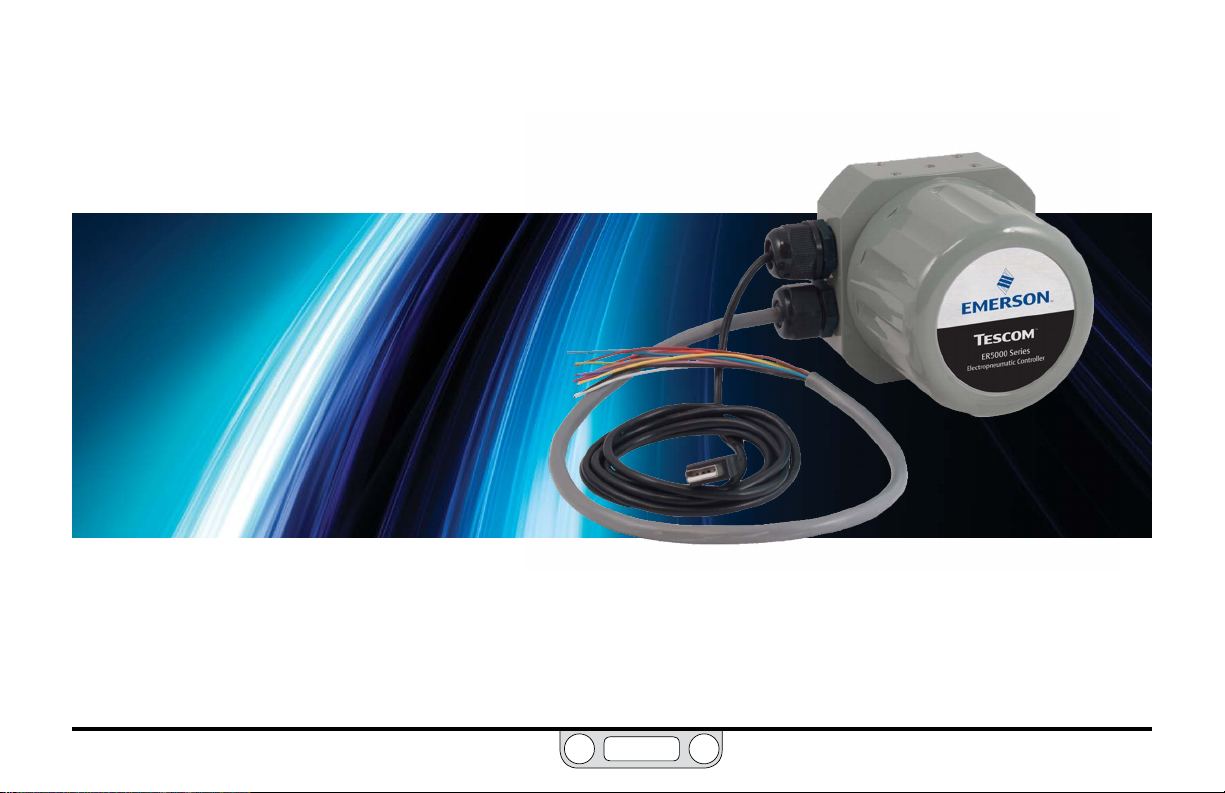
GettInG
BACK
tarted
S
www.emerson.com/tescom
57
Page 58

ER5000 — 58Getting Started
BACK
Before You Begin
WARNING
Investigate and apply the most recent standards for Hazardous Locations for your area set by ANSI, ISO and OSHA , as well as all electrical
codes and fire and safet y standards, to determine if your application will require a Hazardous Location model.
WARNING
Avoid personal injury or property damage from sudden release of pressure or bursting parts. Before proceeding with any
installation procedures:
• Always wear protective clothing, gloves and eyewear to prevent personal injury or property damage.
• Do not remove the ER5000 or any other component of the system while the system is pressurized.
• Disconnect any operating lines providing air pressure, electric power or a control signal to the ER5000 prior to installation
or maintenance.
• Use bypass valves or completely shut off the process to isolate the ER5000 and associated equipment from process pressure prior
to installation or maintenance. Relieve process pressure on both sides of the controller and associated equipment.
• Use lock-out procedures to be sure that the above measures stay in effect while you work on the equipment.
• Che ck with your proces s or safety engin eer for any additio nal measures that m ust be taken to prote ct against pro cess media dange rs.
Do not install, operate or maintain an ER5000 controller or any associated equipment, without reading and fully understanding the
installation guidelines and operating instructions for every component of your application. To avoid personal injury or property
damage, it is important to carefully read, understand and follow all contents of this manual, including all safety cautions and
warnings in the Safety, Installation & Operations Precautions section. If you have any questions about these instructions, contact
your TESCOM™ sales ofce before proceeding.
www.emerson.com/tescom
Page 59

ER5000 — 59Getting Started
BACK
ER5000 Quick Reference: Jumpers, Terminal Blocks and Wires and LEDs
Terminal Blocks and WiresJumpers: 4–20 mA / 1–5V Models
Jumper J6
External Feedback
ON = 4–20 mA
OFF = 1–5V
Jumper J5
Setpoint
ON = 4–20 mA
OFF = 1–5V
Jumper J1
Ground Filter
Bypass
ON = Signal ground
connected to power ground
OFF = Normal mode, no
connection (recommended)
Jumpers: 0–10V Models
Auxiliary Input #1
ON = 4–20 mA
Jumper J15
Auxiliary Input #2
ON = 4–20 mA
OFF = 1–5V
Jumper J9
ER3000 / ER5000
Mode Select
ON = ER3000
OFF = ER5000
Jumper J14
OFF = 1–5V
12-Pin MTA Connector
to J3 Terminal Block
Pin 1
Pin 2
Pin 3
Pin 4
Pin 5
Pin 6
Pin 7
Pin 8
Pin 9
Pin 10
Pin 11
Pin 12
8-Pin MTA Connector
to J4 Terminal Block
Pin 1
Pin 2
Pin 3
Pin 4
Pin 5
Pin 6
Pin 7
Pin 8
Standard
all models
Auxiliary
“F” models only
“F” Models feature a single 20-wire cable
J3 Pins Wire Color Function
1 brown +setpoint input
2 red -setpoint input
3 orange +feedback input
4 yellow -feedback input
5 green -RS485 network connection
6 blue +RS485 network connection
7 violet +24V DC power
8 gray 24V return (power ground)
9 white +5V output (5 mA max.)
10 black analog signal/board ground
*11 *pink analog signal output
12 tan analog signal/board ground
J4 Pins Wire Color Function
1 brown/white +aux input #1
2 red/black -aux input #1
3 orange/black +au x input #2
4 yellow/black -aux input #2
5 green/white suspend control
6 black/white digital output/board ground
7 blue/white digital output #1
8 gray/black digital output #2
Standard Models feature a single 12-wire cable
(active in Enhanced “F” models ONLY)
Jumper J1
Ground Filter
Bypass
ON = Signal ground
connected to power ground
OFF = Normal mode, no
connection (recommended)
www.emerson.com/tescom
Jumper J9
ER3000 / ER5000
Mode Select
ON = ER3000
OFF = ER5000
LEDs
LED3
Receiving Data
(amber)
blinks when ER5000
is receiving data in
via RS485
LED1
Power Indicator
(red)
should be on
continuously
LED2
Sending Data
(green)
blinks when ER5000
is sending data
out via RS485
LED4
“Heartbeat”
should blink on and off at
(red)
a steady rate
Page 60

ER5000 — 60Getting Started
BACK
1
Verify your shipment
CAUTION
If you are replacing an ER3000 in an existing application, be
sure that you have read Replacing an ER 3000 with an ER5000
before you begin.
WARNING
If you are replacing a Hazardous Location ER3000 in an existing
application, be sure that you have read Installing a Hazardous
Location
Model (ER5050) on page 110 before you begin.
Verify that all of these items are in the box you receive.
1. ER5000 or ER5050 Hazardous Location Electronic
Pressure Controller
2. 3mm hex wrench for cover lock screw (ER5050 model only)
3. 1/2" SAE x 1/8" NPTF adaptor
4. Wiring connectors, pre-installed with strain relief
a. 12-pin MTA connector with 12-wire
18" / 45.7 cm cable (standard ER5000 models)
b. 12-pin and 8-pin MTA connectors with single 20-wire
18" / 45.7 cm cable (“F” model ER5000s)
5. USB cable with integrated strain relief (ER5000 models only)
1
4a
5
4b
3
2
www.emerson.com/tescom
Figure 6: What’s In The Box
Page 61

ER5000 — 61Getting Started
IMPORTANT!IMPORTANT!
IMPORTANT!IMPORTANT!
BACK
Verify your shipment (cont.)
Additional items not included:
• 24V DC power supply*
• Setpoint signal source such as an analog output device*,
PC or PLC
• Dome loaded or air actuated pressure regulator*
• Transducer for external feedback*
• 1/8" NPTF tting for ER5000 Inlet Port
• Instrument grade air or Nitrogen supply —
> ER5000: 120 psig / 8.2 bar maximum
> ER5050: 110 psig / 7.5 bar maximum
• Computer for setup and tuning
• Wiring connectors such as a terminal strip or wiring nuts
NOTENOTE
Items with an asterisk (*) are available from TESCOM™.
Tools you will need for the installation:
• Adjustable wrench
• Teon tape
• Wire strippers
www.emerson.com/tescom
Additional items and tool you will need for an installation in a Hazardous Location:
• Conduit and connectors rated for your Hazardous Location
ER TuneTM software is compatible with the following
operating systems: Windows XP, Windows Vista, Windows 7 and
Windows 8.
Windows 8 users: In order to maintain compatibility
with previous Windows operating systems, the ERTune™ program uses
the .NET Framework 3.5, which is not installed by default in Windows 8.
If you are using Windows 8, you will need to download and install
.NET Framework 3.5 before installing the ERTune™ program. You may
also need to disable Driver Signature Enforcement to install the ER5000
driver. We have provided step-by-step instructions for both these tasks in
Appendix A: Set ting up the ERTune™ Program on Windows 8 PCs.
Page 62

ER5000 — 62Getting Started
BACK
GRAY
+ SUPPLY
YELLOW
TAN
ORANGE
2
Verify the configuration of your application
WARNING
Improper selection of controllers, regulators, valves or accessories
Power
Supply
+24V DC
GROUND
USB Connection
VIOLET
can cause death, serious injury and/or property damage.
WARNING
Installation in a hazardous location requires additional steps not
described in this section. Refer to Installing a Hazardous Location
Model (ER5050) on page 110 for more information.
PC
ER5000 Supply
Pressure
110 psig / 7.5 bar
This section assumes you will be installing the ER5000
in a typical configuration, which is shown in Figure 7 and
includes the following components and connections:
Adaptor
+ SUPPLY
+ OUTPUT
• ER5000SI-1
• Controller is mounted on top of an air actuated pressure
reducing regulator
• 1/2" SAE x 1/8" NPTF adaptor is used to connect
controller to regulator
• External Feedback control mode
• Feedback source is a two-wire 4–20 mA transducer
Regulator
Transducer
• Controller is connected to a PC which is running the
ERTune™ program, connected via USB using the Mini-B USB
port on the ER5000’s control board
Supply Pressure
To Process
For information on other applications and alternative wiring
congurations, refer to the Installation Variations section.
Figure 7: Typical Application Setup of the ER5000
www.emerson.com/tescom
Page 63

ER5000 — 63Getting Started
BACK
3
Verify that all operational requirements
have been met
• Supply pressure must be clean, dry inert gas or
instrument grade air that meets the requirements
of ISA Standard 7.0.01.
• Install lters upstream of the mechanical regulator,
as well as the ER5000, to prevent contamination
and excess moisture from entering either device.
• Check that all supply lines, ttings, connections,
lters, valves and gauges have adequate pressure
ratings for the operating conditions.
• Check that the mechanical regulator’s dome port
mates correctly with the 1/2" SAE x 1/8" NPTF
adaptor. Additional ttings may be required.
• Follow the appropriate industrial standards for the
intended function.
Verify that all safety requirements have been met
Read and be sure you understand, all warnings and cautions in
the Safety, Installation & Operations Precautions section.
WARNING
• Improper selection, im proper installation, improper maintenance,
misuse or abuse of this controller or related accessories can cause
property damage, serious injury or death.
• Supply pressure must be clean, dry inert gas or air that meets the
requirements of ISA Standard 7.0.01.
• Severe personal injury or property damage may occur from an
uncontrolled process if the instrument supply medium is not
clean, dry, oil free, nonflammable and noncorrosive. While use
and regular maintenance of a filter that removes particles larger
than 40 micrometers in diameter will suffice in most applications,
further filtration down to 10 micrometer particle size is
recommended. Moisture should be kept to a minimum.
WARNING
Installation in a hazardous location requires additional steps not
described in this section. Refer to Installing a Hazardous Location
Model (ER5050) on page 110 for more information.
www.emerson.com/tescom
Page 64

ER5000 — 64Getting Started
NOTENOTE
BACK
4
Mount the ER5000 on the regulator
Your application may require additional ttings.
WARNING
Installation in a hazardous location requires additional steps
not described in this section. Refer to Installing a Hazardous
Location
Model (ER5050) on page 110 for more information.
Figure 8: Mount the ER5000 on the Regulator
www.emerson.com/tescom
Page 65
ER5000 — 65Getting Started
BACK
5
Connect and verify the power supply
The ER5000 requires a 24V DC power supply, such as the
TESCOM™ 82575-25 or 82575-50 power supply unit.
WARNING
• Select wiring and/or cab le glands that are rated for the
environment of use. Failure to use properly rated wiring
and/or cable glands can result in personal injury or p roperty
damage.
• Wiring connections must be in accordance with local,
regional and national codes for any given area. Failure to
follow the local, regional and national codes could result
in personal injury or property damage.
• To avoid personal injury resulting from electrical shock,
Installation in a hazardous location requires additional steps
not described in this section. Refer to Installing a Hazardous
Location
Model (ER5050) on page 110 for more information.
never connect the controller or associated equipment
to a supply source having a voltage greater than the
maximum rated voltage of this controller or the
associated equipment. Make sure that the components
used in the electronic system are compatible with and
have the proper voltage rating.
WARNING
www.emerson.com/tescom
Page 66

ER5000 — 66Getting Started
BACK
Connect and verify the power supply (cont.)
1. Refer to Table 2 below and Figure 9 to verify correct wiring.
Table 2: Main Cable Wiring for Power Supply
J3 Pins Wire Color Function
1 brown +setpoint input
2 red -setpoint input
3 orange +feedback input
4 yellow -feedback input
5 green -RS485 network connection
6 blue +RS485 network connection
7 violet +24V DC power
8 gray 24V return (power ground)
9 white +5V output (5 mA max.)
10 black analog signal/board ground
*11 *pink analog signal output
12 tan analog signal/board ground
(active in Enhanced “F” models ONLY)
2. For standard model ER5000s, the 12-pin MTA connector comes pre-installed
to the J3 terminal block. For “F” model ER5000s, the standard 12-pin MTA
connector and auxiliary 8-pin MTA connector come pre-installed to the J3 and
J4 blocks.
3. Connect the violet wire (Pin 7) to the +24V DC wire from the power supply.
4. Connect the gray wire (Pin 8) to the ground wire from the power supply.
www.emerson.com/tescom
Standard
Installation
(continu ed next pag e)
Power
Supply
Supply Pressure
Controller
+24V DC
GROUND
Adaptor
Regulator
5. Plug in the power supply.
VIOLET
GRAY
To Process
(continued next page)
Page 67

ER5000 — 67Getting Started
NOTENOTE
BACK
Figure 9: Connect the ER5000 to the Power Supply
Connect and verify the power supply (cont.)
WARNING
DO NOT open cover when an explosive atmosphere is present.
Doing so can result in property damage, serious injury or death.
Refer to Installing a Hazardous Location
Model (ER5050) on page 110 for more information.
6. Unscrew and remove the cover of the ER5000 to view the
control board. Refer to Figure 10.
7. Check that the Power Indicator LED (LED1) is lit, which
indicates power is being supplied.
8. Check that the “Heartbeat” LED (LED4) blinks, which indicates
that the embedded controller software is running.
transmission when the ER5000 communicates using RS485.
These LEDs do not respond to data transmission when the ER5000
LED2 (green) and LED3 (amber) respond to data
LED1
Power Indicator
(red)
should be on
continuously
communicates using USB and may be on or off depending
on the specic conguration of your application. They do
not need to be checked during installation or operation
when USB is used.
LED4
“Heartbeat”
(red)
should blink
on and off at a
steady rate
www.emerson.com/tescom
Page 68
ER5000 — 68Getting Started
NOTENOTE
BACK
9. Unplug the power supply.
Figure 10: These LEDs Indicate That the ER5000 Has Been Successfully Connected to
Verify the Jumper J6 configuration
WARNING
6
www.emerson.com/tescom
The controller must be disconnected from the power
supply before any additional wiring or change to jumper
configuration is performed. Do not reconnect the power
supply until all additional wiring connections have been
made and are properly installed.
WARNING
DO NOT open cover when an explosive atmosphere is present.
Doing so can result in property damage, serious injury or death.
Refer to Installing a Hazardous Location
Model (ER5050) on page 110 for more information.
If you are replacing an ER3000 in an existing application
and wish to continue using your current software such as the
Windows Tune program, you will need to install Jumper J9. The
default conguration for Jumper J9 is NOT installed.
With the cover still removed, inspect Jumper J6. Refer to
Figure 11.
• For connection to a 4–20 mA transducer, the jumper should
be installed.
• For connection to a 1–5V transducer, the jumper should
the Power Supply
NOT be installed.
Page 69

ER5000 — 69Getting Started
BACK
Jumper J6
External Feedback
ON = 4–20 mA
OFF = 1–5V
Jumper shown
installed
for 4–20 mA
feedback source.
Jumper J9
ER3000 / ER5000
Mode Select
Congure to ON if you are
replacing an ER3000 and you
wish to continue using your
current software. Jumper is
OFF by default.
7
Figure 11: Inspect Configuration of J6 Jumper
Connect the transducer wiring to provide a
feedback signal
WARNING
The controller must be disconnected from the power supply before
any additional wiring or change to jumper configuration is
performed. Do not reconnect the power supply until all additional
Power
Supply
Supply Pressure
+24V DC
GROUND
Adaptor
Regulator
VIOLET
GRAY
+ SUPPLY
YELLOW
TAN
To Process
wiring connections have been made and are
ORANGE
Transducer
+ SUPPLY
+ OUTPUT
www.emerson.com/tescom
Page 70

ER5000 — 70Getting Started
NOTENOTE
BACK
WARNING
properly installed.
Installation in a hazardous location requires additional steps not
described in this section. Refer to Installing a Hazardous Location
Model (ER5050) on page 110 for more information.
1. Refer to Table 3 below to verify correct wiring.
Table 3: Main Cable Wiring for Power Supply
J3 Pins Wire Color Function
1 brown +setpoint input
2 red -setpoint input
3 orange +feedback input
4 yellow -feedback input
5 green -RS485 network connection
6 blue +RS485 network connection
7 violet +24V DC power
8 gray 24V return (power ground)
9 white +5V output (5 mA max.)
10 black analog signal/board ground
*11 *pink analog signal output
12 tan analog signal/board ground
(active in Enhanced “F” models ONLY)
Standard
Installation
(continu ed next pag e)
Figure 12: Connect the ER5000 to External Transducer
Connect the transducer wiring to provide a
feedback signal (cont.)
2. Connect the orange feedback input wire (Pin 3) to the
signal output of the transducer, which is Pin 2 or B on
TESCOM™ transducers.
3. Connect the positive wire from the 24V DC power supply
to the power input of the transducer, which is Pin 1 or A on
TESCOM transducers.
4. Connect the yellow feedback return wire (Pin 4) to the tan
analog ground wire (Pin 12).
This is necessary to complete the ground circuit for the
signal from the transducer.
For other applications and wiring congurations, refer to the
Installation Variations section.
www.emerson.com/tescom
Page 71
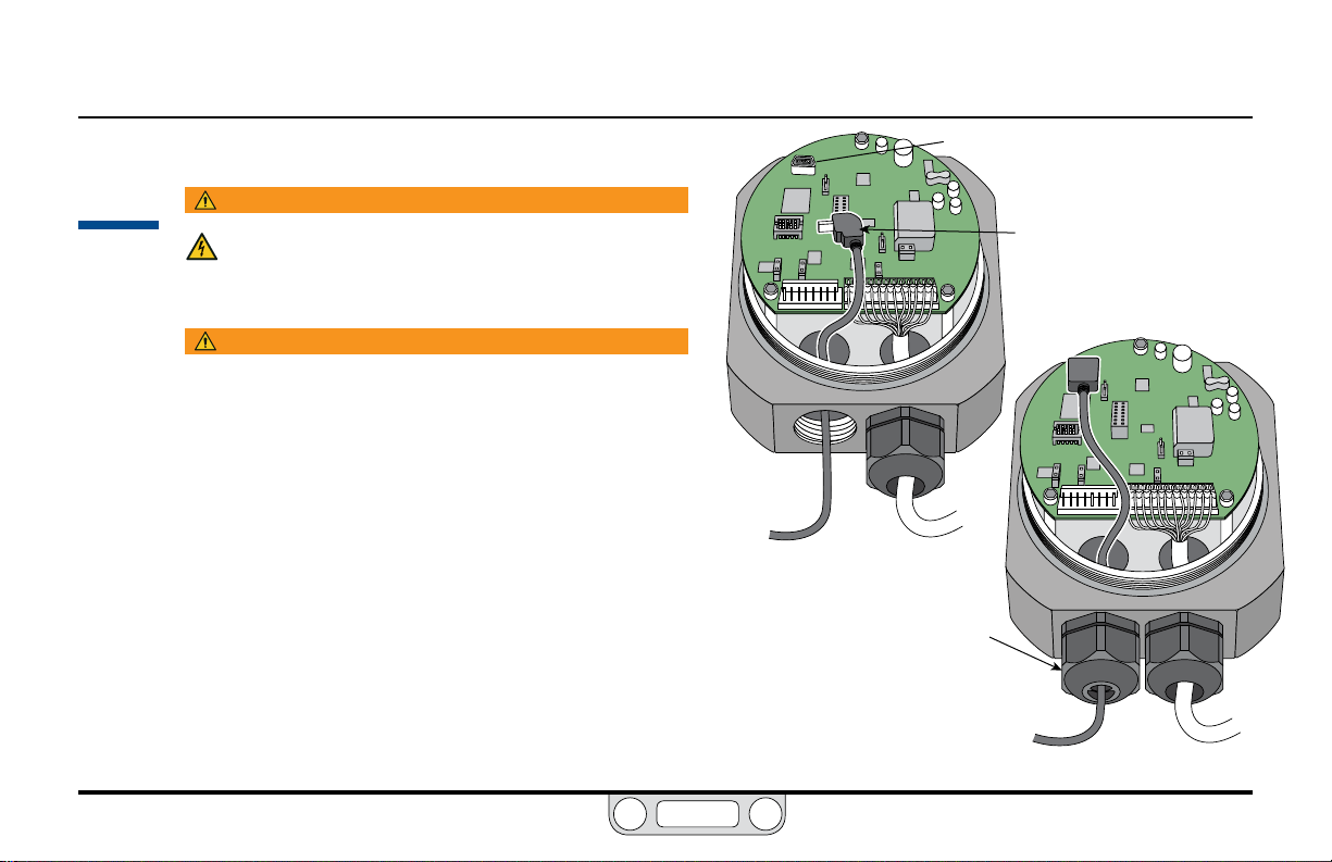
ER5000 — 71Getting Started
BACK
8
Connect the USB cable (not supplied with ER5050)
WARNING
The controller must be disconnected from the power
supply before any additional wiring or change to jumper
configuration is performed. Do not reconnect the power
supply until all additional wiring connections have been
made and are properly installed.
WARNING
Refer to Installing a Hazardous Location
Model (ER5050) on page 110 for more information on wiring in
a Hazardous Location application. Refer to page 89 through
page 93 for correct wiring variations using RS485.
The cable included with the ER5000 has a standard USB A
connector on one end and a 90° Mini-B connector on the other.
1. Slide the Mini-B connector into the left conduit port in the
base of the ER5000 as shown in Figure 13.
2. Thread the cable over the control board and plug it into
the Mini-B USB port.
3. Remove any excess slack in the cable and secure the
integrated strain relief into the conduit port.
4. Plug the cable’s USB A connector into the computer that
will run the ERTune™ program.
5. Screw the cover back onto the ER5000 until you have a
tight t and plug in the power supply.
Figure 13: Connect the USB Cable
Mini-B Port
Integrated USB
Strain Relief
90° Mini-B Connector
www.emerson.com/tescom
Page 72

ER5000 — 72Getting Started
IMPORTANT!IMPORTANT!
NOTENOTE
NOTENOTE
BACK
9
Install the ERTune™ program
If you are using Windows 8, be sure you
have read the note at the end of Step 1.
1. You will need to have the following information on
hand when you start the program for the rst time:
• The model number of your ER5000, which is
located on the label of the controller.
• The series number, part number and serial
number of the regulator you are using.
5. The ER5000 Setup Wizard screens are shown in Figure
14. Use the information from Step 1 to complete setup.
For most screens, the default values will be correct for
your application.
6. Tune the ER5000 according to the instructions in The
ERTune™ Program: Basic Features section.
4
5
6
• The range of your external feedback transducer.
2. Download the ER5000 Software and Manual le
which can be found at TESCOM.com under the
“Download ER5000 Software and Manual” link.
Once the le is downloaded, extract the zip le,
click on the .exe le, and the ER5000 User Support
Software and Manual menu will open.
3. In the menu, click Install ERTune. When installation
is complete, click Close.
The ERTune™ program is available in English,
German and Chinese versions. When installation begins,
the installer checks the default language settings for the
computer and if German or Chinese are detected, the
corresponding translated version is installed. Otherwise,
the English version is installed.
4. Locate the ERTune program listing in the Start
1
2
3
Figure 14: Setup Sequence for ERTune
If you see the
Communication Error window,
as shown in Figure 15, click
the Search Ports button. If the
program does not start, refer to
the Troubleshooting section.
Figure 15: The Comm Error
(Communication Error) Window
™
Software
menu and open it.
www.emerson.com/tescom
Page 73

ER5000 — 73Getting Started
BACK
10
Connect pressure to the system
WARNING
• Never connect the controller or any associated
• Supply pressure must be clean, dry inert gas or air that
• The ER5000 exhausts pilot pressure to the surrounding
Connect the inlet pressure source to the Inlet Port,
marked IN on the b ase of the ER5000. Refer to Figu re 16.
a. The Exhaust Port vents to atmosphere.
b. The output pressure is the regulated pressure that
equipment to a supply source having a pressure
greater than the maximum rated pressure of this
controller or the associated equipment.
meets the requirements of ISA Standard 7.0.01.
atmosphere. When installing this unit in a confined
area, the exhaust port should be remotely vented to
a safe location to prevent asphyxiation due to lack of
Oxygen in the surrounding atmosphere.
passes through the Outlet Port on the bottom of
the controller into the dome of the regulator. Refer
to Dimensions – Top and Bottom View.
(continu ed next pag e)
ER5000 Series
Electropneumatic Controller
Exhaust Port Vents
to Atmosphere
Inlet Pressure
Connected to
Inlet Port
Pressure Gauge
Attached to
Gauge Port
Figure 16: Pressure Connections
ER5000 Series
Electropneumatic Controller
www.emerson.com/tescom
Page 74

ER5000 — 74Getting Started
NOTENOTE
BACK
Connect pressure to the system (cont.)
c. Leave the Gauge Port plugged to prevent leakage or
attach a pressure gauge, as shown in Figure 16 on the
previous page.
For side-mounted applications, the Gauge Port
can be used as the outlet. Plug the Outlet Port at the
bottom of the controller for these applications.
www.emerson.com/tescom
Page 75

ER5000 — 75Getting Started
BACK
11
Start up and tune the system
WARNING
• Start up sequence for electropneumatic controllers is:
a. Feedback loop must be installed and operational.
b. Electrical power should be applied and system setpoint reduced to
its lowest pressure output before turning on the pneumatic supply to
the controller.
c. Apply pressure to the system gradually, avoiding a sudden surge of
fluid or pressure shock to the equipment in the system.
• To avoid personal injury and property damage, keep hands, tools and
other objects away when applying power to the controller.
• Changes to the instrument setup may cause changes in the output
pressure. Depending on the application, these changes may upset process
control, which may result in personal injury or property damage.
• Most controls in the ERTune™ program operate in real time and have
an immediate effect on system performance. Be aware of system
limitations before you change the settings of a control. Depending on
the application, these changes may upset the process control, which
may result in personal injury or property damage.
The ER5000 is now fully installed. Connect the regulator supply
pressure to the Inlet Port of the regulator.
The system performance can be checked and, if desired, optimized
further using the ERTune™ program.
Refer to The ERTune™ Program: Basic Features section for further details
and recommendations on tuning the pressure control system.
Power
Supply
PC
ER5000 Supply
Pressure
110 psig / 7.5 bar
Supply Pressure
Figure 17: The Completed ER5000 Installation
+24V DC
GROUND
USB Connection
Adaptor
Regulator
VIOLET
GRAY
+ SUPPLY
YELLOW
TAN
To Process
ORANGE
Transducer
+ SUPPLY
+ OUTPUT
www.emerson.com/tescom
Page 76

InStallatIon
BACK
arIatIonS
V
www.emerson.com/tescom
76
Page 77

ER5000 — 77Installation Variations
BACK
Before You Begin
WARNING
Investigate and apply the most recent standards for Hazardous Locations for your area set by ANSI, ISO and OSHA , as well as all electrical codes
and fire and safety standards, to determine if your application will require a Hazardous Location model. If your application requires a Hazardous
Location model (ER5050), refer to Installing a Hazardous Location
Model (ER5050) on page 110 before following the steps listed in this section.
WARNING
Avoid personal injury or property damage from sudden release of pressure or bursting parts. Before proceeding with any
installation procedures:
• Always wear protective clothing, gloves and eyewear to prevent personal injury or property damage.
• Do not remove the ER5000 or any other component of the system while the system is pressurized.
• Disconnect any operating lines providing air pressure, electric power or a control signal to the ER5000 prior to installation
or maintenance.
• Use bypass valves or completely shut off the process to isolate the ER5000 and associated equipment from process pressure prior
to installation or maintenance. Relieve process pressure on both sides of the controller and associated equipment.
• Use lock-out procedures to be sure that the above measures stay in effect while you work on the equipment.
• Che ck with your proces s or safety engin eer for any additio nal measures that m ust be taken to prote ct against pro cess media dange rs.
Do not install, operate or maintain an ER5000 controller or any associated equipment, without reading and fully understanding the
installation guidelines and operating instructions for every component of your application. To avoid personal injury or property
damage, it is important to carefully read, understand and follow all contents of this manual, including all safety cautions and
warnings in the Safety, Installation & Operations Precautions section. If you have any questions about these instructions, contact
your TESCOM™ sales ofce before proceeding.
www.emerson.com/tescom
Page 78

ER5000 — 78Installation Variations
NOTENOTE
NOTENOTE
NOTENOTE
BACK
ER5000 Installation Variations — Wiring Diagrams
The ER50 00 has a wide range of wiring options, allowing it to be congured for virtually any application requirement. If your application calls for a variation on the
standard installation, use the diagrams on the following pages to build a complete conguration. Note that in your actual application, multiple wires may terminate
at the same connec tion: for example, the violet wire (Pin 7), which is the (+) connection to the power source, may also connect directly to the transducer or other
external devices.
If your application requires a Hazardous Location model (ER5050), read Installing a Hazardous Location
Model (ER5050) on page 110 before following the steps listed below.
Step 1: Connect the ER 5000 to a
24V DC Power Supply
All wir ing congura tions begin by
connec ting the ER5 000 to a 24V DC
power su pply. The exte rnal power
supply i s necessar y for the contro ller to
opera te and is part of all applications.
Power Supply page82
This sec tion shows v ariations to t he
typ ical ER5000 c onguratio n described i n the
Gett ing Starte d section.
The (+) and the (-) in the tab les and
gures o f this sectio n refer to the dif ferential
input s. Both must be co nnected fo r the system
to work p roperly.
Setpo int is set digit ally by writ ing to
variab le #37 (ID_SETPO INT), using the ER Tune
progr am or your own cod ing. Refer to the Inter nal
Variables and the ER5000 Soft ware Development
Support sections for more information.
Step 2: Connect the Setpoint and Feedback Source
Setpo int and feedb ack sources v ary with a pplicatio n. Use the link s below to mat ch the setpo int and
feedba ck sources for your app lication to spec ic wiring diagr ams and descripti ons in this sectio n.
Click a pa ge number to go t o that diagram ; click the BACK bu tton to ret urn to this pag e.
Setpoint Source
Prole None
Analo g (Potentiom eter) page83
Analo g (Current/Vo ltage) pa ge84
Analo g
(Passiv e PC or PLC D/A Card)
Analo g
(Acti ve PC or PLC D/A Card)
Prol e with Ext ernal Cont rol pag e87
(RS232 to RS 485 Conver ter)
Digital
(USB to RS 485 Convert er)
Digital
(RS232 to RS 485 Netwo rk)
Digital
(USB to RS 485 Networ k)
Digital
™
Digital (USB) USB cab le
page85
page86
page89
page90
page91
page93
Feedback Source
Internal None
Two Wire Transducer pa ge95
Three Wire Transducer page96
Four Wire Transducer page97
4–20 mA E xternal Fe edback, Fl oating Inpu t,
Feedba ck Signal Monito red by PC or PLC A/D Card
4–20 mA E xternal Fe edback, Gr ound
Referenced Input, Feedback Signal Monitored
by PC or PLC A /D Card
Two Wire Trans ducer, PC/PLC Use d to Monitor
Voltag e Through ER 5000 Inter nal Resistor
Three W ire Transduce r, PC/PLC Used to Mo nitor
Voltag e Through ER 5000 Inter nal Resistor
Four Wi re Transducer, PC/P LC Used to Monit or
Voltag e Through ER 5000 Inter nal Resistor
Switch F eedback Con trol to a Seco nd Feedback
Source
Step 3: If Ap plicable, Connect
Wiring for Additional Functions
Some ap plications c all for
monitoring and control connections
in addit ion to the sta ndard trio of
power, setpoint and feedback.
page98
page99
page100
page101
page102
page103
Monitoring Additional
Analo g Inputs
Monit oring the Int ernal
Senso r, 4–20 mA Wi ring
Monit oring the Int ernal
Senso r, 0–10V Wiring
Digital Outputs pa ge107
Suspend Mode page109
page104
page105
page106
www.emerson.com/tescom
Page 79

ER5000 — 79Installation Variations
BACK
Terminal Blocks and Wires
There are two terminal blocks on the control board of the
ER5000. The 12-pin J3 terminal block is active for all models of the
controller. The auxiliary 8-pin J4 terminal block is only active for
“F” model controllers.
All ER5000s feature a 12-pin MTA
connector to the J3 terminal block.
“F” model ER5000s also feature an
auxiliary 8-pin MTA connector to the J4
terminal block.
Previous versions of the “F” model
controller featured separate cables
for the standard and auxiliary
connectors. For “F” model ER5000s,
both connectors are fed by a single
20-wire cable.
Figure 18: Wires and Terminal Block Pins
12-Pin MTA Connector
to J3 Terminal Block
Pin 1
Pin 2
Pin 3
Pin 4
Pin 5
Pin 6
Pin 7
Pin 8
Pin 9
Pin 10
Pin 11
Pin 12
8-Pin MTA Connector
to J4 Terminal Block
Pin 1
Pin 2
Pin 3
Pin 4
Pin 5
Pin 6
Pin 7
Pin 8
Wires are color coded for easy identication. Wires that feed the
J3 terminal block are solid colors and wires that feed the J4 block
are color striped, as shown in Figure 18.
Standard
all models
Auxiliary
“F” models only
“F” Models feature a single 20-wire cable
Standard Models feature a single 12-wire cable
J3 Pins Wire Color Function
1 brown +setpoint input
2 red -setpoint input
3 orange +feedback input
4 yellow -feedback input
5 green -RS485 network connection
6 blue +RS485 net work connection
7 violet +24V DC power
8 gray 24V return (power ground)
9 white +5V output (5 mA max.)
10 black analog signal/board ground
*11 *pink analog signal output
12 tan analog signal/board ground
J4 Pins Wire Color Function
1 brown/white +aux input #1
2 red/black -aux input #1
3 orange/black +aux input #2
4 yellow/black -aux input #2
5 green/white suspend control
6 black/white digital output/board ground
7 blue/white digital output #1
8 gray/black digital output #2
(active in Enhanced “F” models ONLY)
www.emerson.com/tescom
Page 80
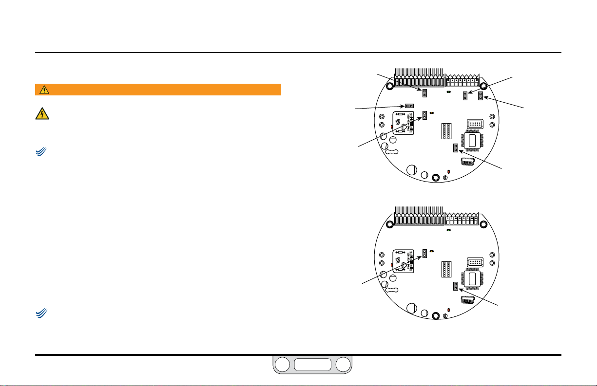
ER5000 — 80Installation Variations
NOTENOTE
NOTENOTE
BACK
Voltage/Current Select Jumpers
WARNING
The controller must be disconnected from the power supply before
any additional wiring or change to jumper configuration is
performed. Do not reconnect the power supply until all additional
wiring connections have been made and are properly installed.
If you are replacing an ER3000 in an existing application and
wish to continue using your current software such as the Windows Tune
program, you will need to install Jumper J9. The default conguration
for Jumper J9 is NOT installed.
Figure 19 shows the voltage/current select jumpers on
the ER5000.
Jumpers J5, J6, J14 and J15 are used to select between 4–20 mA
and 1–5V sources for setpoint, external feedback, auxiliary
input #1 and auxiliary input #2 respectively. For these jumpers,
having the jumper installed (ON) congures the controller
for 4–20 mA input and having the jumper not installed (OFF)
congures the controller for 1–5V input.
0–10V models of the ER5000 do not have these jumpers.
(continu ed next pag e)
Jumper J6
External Feedback
ON = 4–20 mA
OFF = 1–5V
Jumper J5
Setpoint
ON = 4–20 mA
OFF = 1–5V
Jumper J1
Ground Filter
Bypass
ON = Signal ground
connected to power
ground
OFF = Normal mode,
no connection
(recommended)
Jumper J1
Ground Filter
Bypass
ON = Signal ground
connected to power ground
OFF = Normal mode, no
connection (recommended)
4–20 mA / 1–5V Models
0–10V Models
Figure 19: Jumpers
Jumper J14
Auxiliary Input #1
ON = 4–20 mA
OFF = 1–5V
Jumper J15
Auxiliary Input #2
ON = 4–20 mA
OFF = 1–5V
Jumper J9
ER3000 / ER5000
Mode Select
ON = ER3000
OFF = ER5000
Jumper J9
ER3000 / ER5000
Mode Select
ON = ER3000
OFF = ER5000
www.emerson.com/tescom
Page 81

ER5000 — 81Installation Variations
NOTENOTE
BACK
The recommended conguration for the Ground Filter
Bypass jumper (J1) is not installed (OFF). Installing this jumper
connects signal ground directly to the power supply ground.
This conguration is rarely used and should only be considered
when there is an extreme level of operational noise. Refer to the
Troubleshooting section before installing this jumper.
LED Indicators
Figure 20 shows the position of the four LED indicators on the
circuit board of the ER5000. The LED indicators give you a quick
visual reference to evaluate the status of the controller.
During installation, use LED1 (red) and LED4 (red) to verify that
you have correctly wired the ER5000 to its power supply.
If you are communicating via RS485, for example as part of a
daisychain on a network, LED2 (green) and LED3 (amber) verify
that the ER5000 is sending and receiving data.
Refer to page 89 through page 93 for correct wiring to
connect the ER5000 to an RS485 converter.
NOTENOTE
LED2 and LED3 respond to data transmission when the
ER5000 communicates using RS485. These LEDs do not respond to dat a
transmission when the ER5000 communicates using USB and may be on or
off depending on the specic conguration of your application. They do not
need to be checked during installation or operation when USB is used.
The LEDs can help you troubleshoot controllers that are not
functioning properly. For further information, refer to the
Troubleshooting section.
LED3
Receiving Data
(amber)
blinks when ER5000
is receiving data in via
RS485
LED1
Power Indicator
(red)
should be on
continuously
should blink on and off at
Figure 20: LED Indicators
Sending Data
blinks when ER5000
is sending data
out via RS485
LED4
“Heartbeat”
(red)
a steady rate
LED2
(green)
www.emerson.com/tescom
Page 82
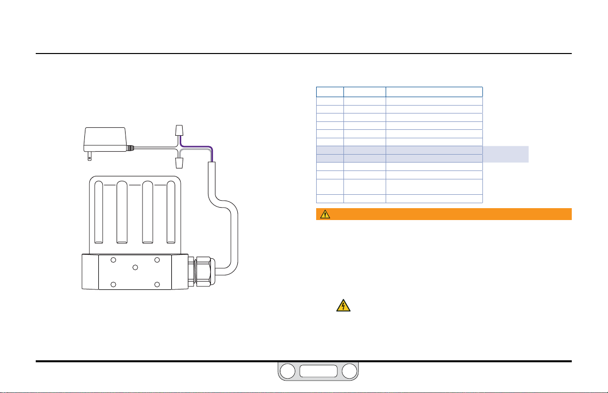
ER5000 — 82Installation Variations
BACK
Power Supply Wiring — All Applications
All ER5000s, regardless of conguration or application, must rst
be wired to a 24V DC power supply, as shown in Figure 21.
POWER
SUPPLY
Figure 21: Wiring to 24V DC Power Supply
+24V DC
GROUND
VIOLET
GRAY
Refer to Table 4 to verify correct wiring.
Table 4: Wiring to 24V DC Power Supply
J3 Pins Wire Color Function
1 brown +setpoint input
2 red -setpoint input
3 orange +feedback input
4 yellow -feedback input
5 green -RS485 network connection
6 blue +RS485 network connection
7 violet +24V DC power
8 gray 24V return (power ground)
9 white +5V output (5 mA max.)
10 black analog signal/board ground
*11 *pink analog signal output
12 tan analog signal/board ground
WARNING
• Select wiring and/or cab le glands that are rated for the environment
of use. Failure to use properly rated wiring and/or cable glands can
result in personal injury or proper ty damage.
• Wiring connections must be in accordance with local, regional
and national codes for any given area. Failure to follow the local,
regional and national codes could result in personal injury or
property damage.
• To avoid personal injury resulting from electrical shock, never
connect the controller or associated equipment to a supply
source having a voltage greater than the maximum rated
voltage of this controller or the associated equipment. Make
sure that the components used in the electronic system are
compatible with and have the proper voltage rating.
(active in Enhanced “F” models ONLY)
www.emerson.com/tescom
Page 83

ER5000 — 83Installation Variations
NOTENOTE
NOTENOTE
BACK
Setpoint Wiring Variations
Analog Setpoint Source — Potentiometer
Figure 22 shows correct wiring to provide a 0–5V signal to the
analog setpoint from a potentiometer.
WARNING
The controller must be disconnected from the power
supply before any additional wiring or change to
jumper configuration is performed. Do not reconnect
the power supply until all additional wiring connections
have been made and are properly installed.
1–5V ER5000s. Refer to The Control Limits Panel for more information on
this feature.
www.emerson.com/tescom
The 0–1V range can be programmed as a Control Limit for
WHITE
BLACK
BROWN
RED
TAN
Figure 22: Potentiometer Analog Setpoint
+5 +10
HIGH
WIPER
LOW
POWER SUPPLY
10V DC
10K
120V AC
Refer to Table 5 to verify correct wiring.
Table 5: Wiring for Potentiometer Analog Setpoint
J3 Pins Wire Color Function
1 brown +setpoint input
2 red -setpoint input
3 orange +feedback input
4 yellow -feedback input
5 green -RS485 network connection
6 blue +RS485 network connection
7 violet +24V DC power
8 gray 24V return (power ground)
9 white +5V ou tput (5 mA max.)
10 black analog signal/board ground
*11 *pink analog signal output
12 tan analog signal/board ground
The ER5000 cannot direc tly provide a 0–10V signal.
An external 10V supply must be used.
(active in Enhanced “F” models ONLY)
Page 84
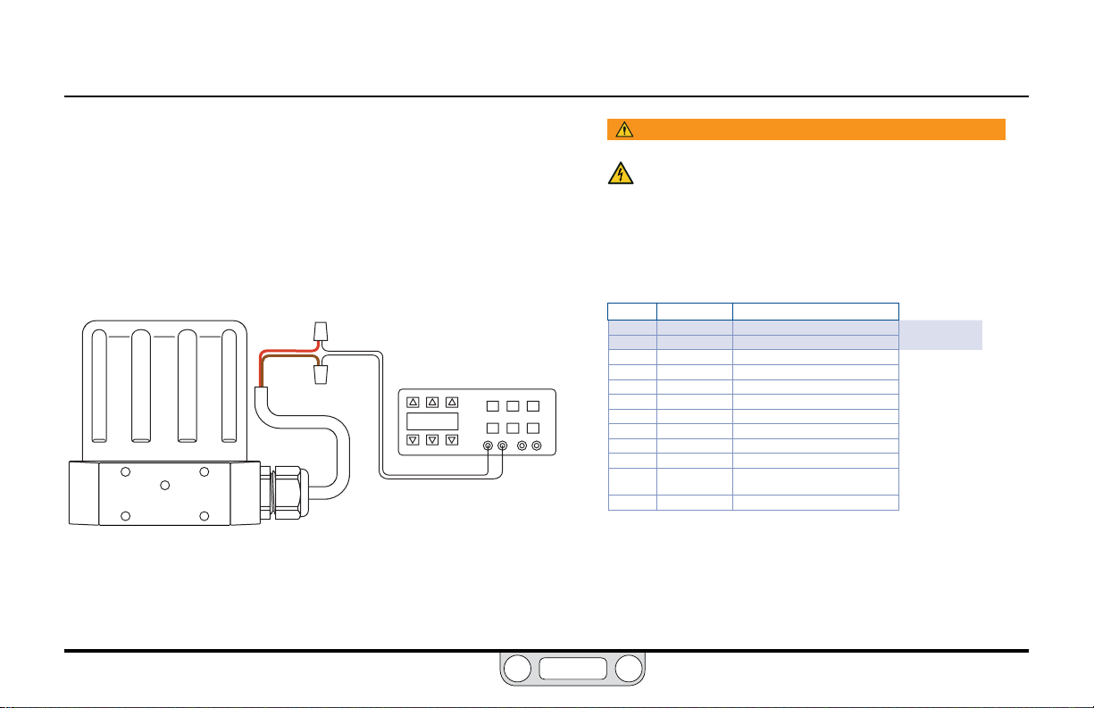
ER5000 — 84Installation Variations
BACK
Setpoint Wiring Variations
Analog Setpoint Source — Current/Voltage
Figure 23 shows how to provide the analog setpoint from an
active variable current or voltage supply.
The negative (-) lead of your source connects to the red wire and
the positive (+) lead connects to the brown wire.
RED
BROWN
Figure 23: Current/Voltage Analog Setpoint
SIGNAL SOURCE
4–20mA or 1–5V or 0–10V
- OUTPUT
+ OUTPUT
WARNING
The controller must be disconnected from the power
supply before any additional wiring or change to jumper
configuration is performed. Do not reconnect the power
supply until all additional wiring connections have been made
and are properly installed.
Refer to Table 6 to verify correct wiring.
Table 6: Wiring for Current/Voltage Analog Setpoint
J3 Pins Wire Color Function
1 brown +setpoint input
2 red -setpoint input
3 orange +feedback input
4 yellow -feedback input
5 green -RS485 network connection
6 blue +RS485 network connection
7 violet +24V DC power
8 gray 24V return (power ground)
9 white +5V output (5 mA max.)
10 black analog signal/board ground
*11 *pink analog signal output
12 tan analog signal/board ground
(active in Enhanced “F” models ONLY)
www.emerson.com/tescom
Page 85
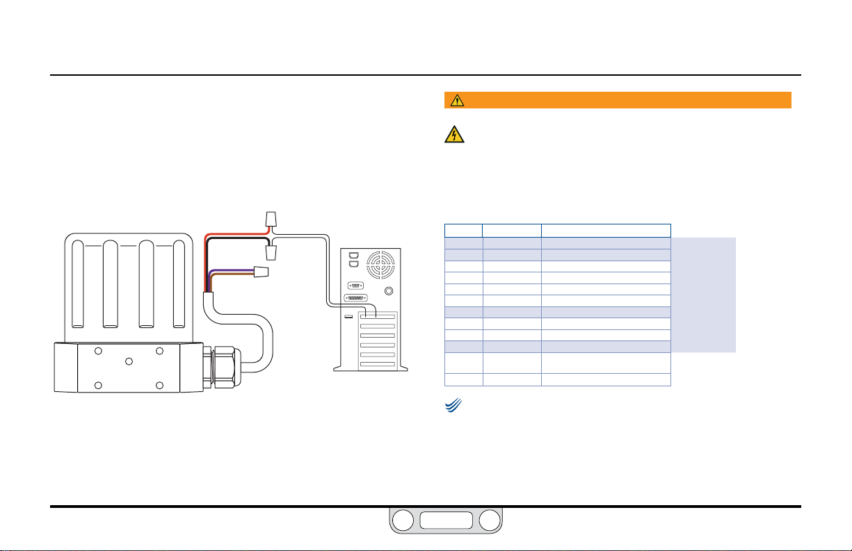
ER5000 — 85Installation Variations
NOTENOTE
BACK
Setpoint Wiring Variations
Analog Setpoint Source — Passive PC or PLC D/A Card
Figure 24 shows correct wiring to provide an analog setpoint from
a PC or PLC D/A card. In this conguration, the ER5000’s 24V DC
power supply supplies power to the passive D/A card.
RED
BLACK
VIOLET
BROWN
Figure 24: Passive PC or PLC D/A Card Analog Setpoint
OUTPUT
COMMON
PC
WARNING
The controller must be disconnected from the power supply before
any additional wiring or change to jumper configuration is
performed. Do not reconnect the power supply until all additional
wiring connections have been made and are properly installed.
Refer to Table 7 to verify correct wiring.
Table 7: Wiring for Passive PC or PLC D/A Card Analog Setpoint
J3 Pins Wire Color Function
1 brown +setpoint input
2 red -setpoint input
3 orange +feedback input
4 yellow -feedback input
5 green -RS485 network connection
6 blue +RS485 network connection
7 violet +24V DC power
8 gray 24V return (power ground)
9 white +5V output (5 mA max.)
10 black analog signal/board ground
*11 *pink analog signal output
12 tan analog signal/board ground
Check that Jumper J6 (refer to Figure 19) is installed for
4–20 mA operation and removed for 1–5V operation. There is no jumper
on the 0–10V ER5000 models.
(active in Enhanced “F” models ONLY)
www.emerson.com/tescom
Page 86

ER5000 — 86Installation Variations
NOTENOTE
BACK
Setpoint Wiring Variations
Analog Setpoint Source — Active PC or PLC D/A Card
Figure 25 shows correct wiring to provide an analog setpoint from
a PC or PLC D/A card. In this conguration, the power is supplied
by the active D/A card.
RED
BROWN
Figure 25: Active PC or PLC D/A Card Analog Setpoint
-
OUTPUT
+ OUTPUT
PC
WARNING
The controller must be disconnected from the power supply before
any additional wiring or change to jumper configuration is
performed. Do not reconnect the power supply until all additional
wiring connections have been made and are properly installed.
Refer to Table 8 to verify correct wiring.
Table 8: Wiring for Active PC or PLC D/A Card Analog Setpoint
J3 Pins Wire Color Function
1 brown +setpoint input
2 red -setpoint input
3 orange +feedback input
4 yellow -feedback input
5 green -RS485 network connection
6 blue +RS485 network connection
7 violet +24V DC power
8 gray 24V return (power ground)
9 white +5V output (5 mA max.)
10 black analog signal/board ground
*11 *pink analog signal output
12 tan analog signal/board ground
Check that Jumper J6 (refer to Figure 19) is installed for
4–20 mA operation and removed for 1–5V operation. There is no jumper
on the 0–10 Volt ER5000 models.
(active in Enhanced “F” models ONLY)
www.emerson.com/tescom
Page 87
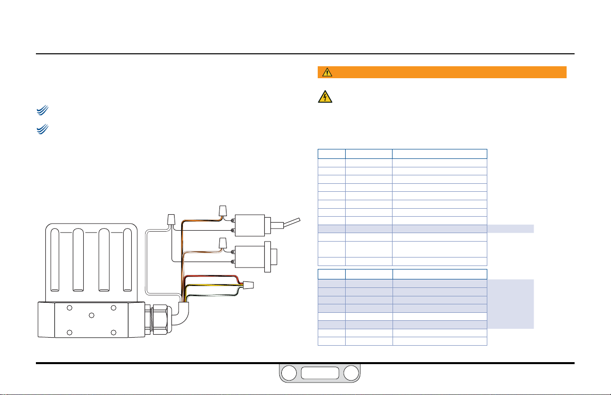
ER5000 — 87Installation Variations
NOTENOTE
NOTENOTE
BACK
Setpoint Wiring Variations
Profile with External Control/Digital Inputs
This feature is only available on “F” models of the ER5000.
Jumpers J14 and J15 must be removed for this application. Refer
to Figure 19.
Figure 26 shows the wiring conguration for controlling a Prole
without using a PC. The Prole that has been downloaded into
the ER5000 in this application can be started or stopped with a
toggle switch.
WHITE
Figure 26: External Profile Control
ORANGE/BLACK
BROWN/WHITE
RED/BLACK
YELLOW/BLACK
BLACK/WHITE
PROFILE
START/STOP
DIGITAL
INPUT
WARNING
The controller must be disconnected from the power supply before
any additional wiring or change to jumper configuration is
performed. Do not reconnect the power supply until all additional
wiring connections have been made and are properly installed.
Refer to Table 9 to verify correct wiring.
Table 9: Wiring for Profile Control Using Auxiliary Inputs
J3 Pins Wire Color Function
1 brown +setpoint input
2 red -setpoint input
3 orange +feedback input
4 yellow -feedback input
5 green -RS485 network connection
6 blue +RS485 network connection
7 violet +24V DC power
8 gray 24V return (power ground)
9 white +5V output (5 mA max .)
10 black analog signal/board ground
*11 *pink analog signal output
12 tan analog signal/board ground
J4 Pins Wire Color Function
1 brown/white +aux input #1
2 red/black -aux input #1
3 orange/black +aux input #2
4 yellow/black -aux input #2
5 green/white suspend control
6 black/white digital output/board ground
7 blue/white digital output #1
8 gray/black digital output #2
(active in Enhanced “F” models ONLY)
(continu ed next pag e)
www.emerson.com/tescom
Page 88

ER5000 — 88Installation Variations
BACK
Profile with External Control/Digital Inputs (cont.)
Additionally, the Digital Input push button can be used if the
“Digital Input” function has been used within the Prole. This allows
an operator the exibility to wait until an event has occurred, such
as changing to the next device.
When Auxiliary Input #2 (orange/black wire, J4 Pin 3) is used as the
Prole Start/Stop signal and Auxiliary Input #1 (brown/white wire,
J4 Pin 1) is used as the Digital Input signal, the ER5000 allows you
to adjust the toggle level (also referred to as the trip point) of the
input. This is the level where the analog input switches between a
logical 0 and a logical 1.
For example, when a pressure transducer is connected to the
Digital Input, this feature allows the ER5000 to wait for a specic
pressure before continuing on in the Prole.
The ER5000 toggle variables enable this feature. Refer to the
ER5000 Analog Input Variables section for more information.
www.emerson.com/tescom
Page 89

ER5000 — 89Installation Variations
BACK
Setpoint Wiring Variations
Digital Setpoint Source — RS485 Connection,
RS232 to RS485 Converter (TESCOM™ Model #85061)
For most applications, the supplied USB cable provides the most
efcient connection to the PC. The controller can also be wired to
connect through an RS485 converter, as shown in Figure 27.
GROUND
+24 V DC
- RS485
+ RS485
Figure 27: RS485 Connection (RS232 to RS485 Converter)
GRAY
VIOLET
GREEN
BLUE
WARNING
The controller must be disconnected from the power supply before
any additional wiring or change to jumper configuration is
performed. Do not reconnect the power supply until all additional
wiring connections have been made and are properly installed.
Refer to Table 10 to verify correct wiring.
Table 10: Wiring for RS485 Connection (RS232 to RS485 Converter)
J3 Pins Wire Color Function
1 brown +setpoint input
2 red -setpoint input
3 orange +feedback input
4 yellow -feedback input
5 green -RS485 net work connection
6 blue +RS485 network connection
7 violet +24V DC power
8 gray 24V return (power ground)
9 white +5V output (5 mA max.)
10 black analog signal/board ground
*11 *pink analog signal output
12 tan analog signal/board ground
(active in Enhanced “F” models ONLY)
The RS232 to RS485 converter requires direct wiring to an
external power supply, so it must be connected to the ER5000’s
power supply wiring. The violet wire (Pin 7) connects to the
+24V DC terminal and the gray wire (Pin 8) connects to the
ground terminal.
www.emerson.com/tescom
Page 90

ER5000 — 90Installation Variations
BACK
Setpoint Wiring Variations
Digital Setpoint Source — RS485 Connection,
USB to RS485 Converter (TESCOM™ Model #82948)
For most applications, the supplied USB cable provides the most
efcient connection to the PC. The controller can also be wired to
connect through an RS485 converter, as shown in Figure 28.
TDA(-)
TDB(+)
Figure 28: RS485 Connection (USB to RS485 Converter)
GREEN
BLUE
WARNING
The controller must be disconnected from the power supply before
any additional wiring or change to jumper configuration is
performed. Do not reconnect the power supply until all additional
wiring connections have been made and are properly installed.
Refer to Table 11 to verify correct wiring.
Table 11: Wiring for RS485 Connection (USB to RS485 Converter)
J3 Pins Wire Color Function
1 brown +setpoint input
2 red -setpoint input
3 orange +feedback input
4 yellow -feedback input
5 green -RS485 net work connection
6 blue +RS485 network connection
7 violet +24V DC power
8 gray 24V return (power ground)
9 white +5V output (5 mA max.)
10 black analog signal/board ground
*11 *pink analog signal output
12 tan analog signal/board ground
(active in Enhanced “F” models ONLY)
The USB to RS485 converter is powered through its USB
connection, so it does not require direct wiring to a power supply.
www.emerson.com/tescom
Page 91

ER5000 — 91Installation Variations
BACK
Setpoint Wiring Variations
Digital Setpoint Source — RS485 Network, RS232
to RS485 Converter (TESCOM™ Model #85061)
The USB protocol isn’t networkable, so applications requiring
multiple controllers must use RS485. RS485, wired through a
converter as shown in Figure 29, allows for up to 32 ER5000s to be
daisychained in a network.
GROUND
+24 V DC
- RS485
+ RS485
GRAY
VIOLET VIOLET
GREEN GREEN GREEN
BLUE BLUE BLUE
Figure 29: Multiple Controllers in an RS485 Network (RS232 to RS485 Converter)
WARNING
The controller must be disconnected from the power supply before
any additional wiring or change to jumper configuration is
performed. Do not reconnect the power supply until all additional
wiring connections have been made and are properly installed.
(continu ed next pag e)
GRAY
GRAY
VIOLET
www.emerson.com/tescom
Page 92

ER5000 — 92Installation Variations
NOTENOTE
NOTENOTE
BACK
Digital Setpoint Source — RS485 Network,
RS232 to RS485 Converter (TESCOM™ Model #85061) (cont.)
Each ER5000 in the network must be assigned a unique Node
Address. All ER5000s are assigned a default Node Address of 250;
therefore, the addresses must be changed to allow them to all
communicate on the network.
The Node Address can be changed as part of the setup procedure
or at any time afterwards using The Congure Tab.
Refer to To set up the ERTune™ program to work with the ER5000
and The Congure Tab for more information on how to modify the
Node Address of the ER5000 using the ERTune™ program.
Repeat this process for each ER5000 in the network. Be sure to
give each controller a unique Node Address within the network.
You may leave one ER5000 at the default value.
The number you assign should be lower than 250. Numbers
higher than 250 will be truncated to the rst two digits.
The power supply for your network must be able to provide
300 mA to each ER5000 in the daisychain.
Refer to Table 12 to verify correct wiring.
Table 12: Wiring for Networked Connection (RS232 to RS485 Converter)
J3 Pins Wire Color Function
1 brown +setpoint input
2 red -setpoint input
3 orange +feedback input
4 yellow -feedback input
5 green -RS485 net work connection
6 blue +RS485 network connection
7 violet +24V DC power
8 gray 24V return (power ground)
9 white +5V output (5 mA max.)
10 black analog signal/board ground
*11 *pink analog signal output
12 tan analog signal/board ground
The RS232 to RS485 converter requires direct wiring to an
external power supply, so it must be connected to the ER5000’s
power supply wiring. The violet wire (Pin 7) connects to the
+24V DC terminal and the gray wire (Pin 8) connects to the
ground terminal.
(active in Enhanced “F” models ONLY)
www.emerson.com/tescom
Page 93

ER5000 — 93Installation Variations
BACK
Setpoint Wiring Variations
Digital Setpoint Source — RS485 Network,
USB to RS485 Converter (TESCOM™ Model #82948)
The USB protocol isn’t networkable, so applications requiring
multiple controllers must use RS485. RS485, wired through a
converter as shown in Figure 30, allows for up to 32 ER5000s to be
daisychained in a network.
TDA(-)
TDB(+)
GREEN GREEN
BLUE
Figure 30: Multiple Controllers in an RS485 Network (USB to RS485 Converter)
WARNING
The controller must be disconnected from the power supply before
any additional wiring or change to jumper configuration is
performed. Do not reconnect the power supply until all additional
wiring connections have been made and are properly installed.
(continu ed next pag e)
GREEN
BLUE
BLUE
www.emerson.com/tescom
Page 94

ER5000 — 94Installation Variations
NOTENOTE
NOTENOTE
BACK
Digital Setpoint Source — RS485 Network,
USB to RS485 Converter (TESCOM™ Model #82948) (cont.)
Each ER5000 in the network must be assigned a unique Node
Address. All ER5000s are assigned a default Node Address of 250;
therefore, the addresses must be changed to allow them to all
communicate on the network.
The Node Address can be changed as part of the setup procedure
or at any time afterwards using The Congure Tab.
Refer to To set up the ERTune™ program to work with the ER5000
and The Congure Tab for more information on how to modify the
Node Address of the ER5000 using the ERTune™ program.
Repeat this process for each ER5000 in the network. Be sure to
give each controller a unique Node Address within the network.
You may leave one ER5000 at the default value.
The number you assign should be lower than 250. Numbers
higher than 250 will be truncated to the rst two digits.
The power supply for your network must be able to provide
300 mA to each ER5000 in the daisychain.
Refer to Table 13 to verify correct wiring.
Table 13: Wiring for Networked Connection (USB to RS485 Converter)
J3 Pins Wire Color Function
1 brown +setpoint input
2 red -setpoint input
3 orange +feedback input
4 yellow -feedback input
5 green -RS485 net work connection
6 blue +RS485 network connection
7 violet +24V DC power
8 gray 24V return (power ground)
9 white +5V output (5 mA max.)
10 black analog signal/board ground
*11 *pink analog signal output
12 tan analog signal/board ground
The USB to RS485 converter is powered through its USB
connection, so it does not require direct wiring to a power supply.
(active in Enhanced “F” models ONLY)
www.emerson.com/tescom
Page 95

ER5000 — 95Installation Variations
NOTENOTE
BACK
Feedback Wiring Variations
Two Wire Transducer
The correct wiring for two wire transducers is shown in Figure 31.
VIOLET
ORANGE
YELLOW
TAN
Figure 31: Two Wire Transducer Wiring
+ SUPPLY
+ OUTPUT
TRANSDUCER
WARNING
The controller must be disconnected from the power supply before
any additional wiring or change to jumper configuration is
performed. Do not reconnect the power supply until all additional
wiring connections have been made and are properly installed.
Refer to Table 14 to verify correct wiring.
Table 14: Wiring for Two Wire Transducer
J3 Pins Wire Color Function
1 brown +setpoint input
2 red -setpoint input
3 orange +feedback input
4 yellow -feedback input
5 green -RS485 network connection
6 blue +RS485 network connection
7 violet +24V DC power
8 gray 24V return (power ground)
9 white +5V output (5 mA max.)
10 black analog signal/board ground
*11 *pink analog signal output
12 tan analog signal/board ground
Check that Jumper J6 (refer to Figure 19) is installed for
4–20 mA operation.
(active in Enhanced “F” models ONLY)
www.emerson.com/tescom
Page 96
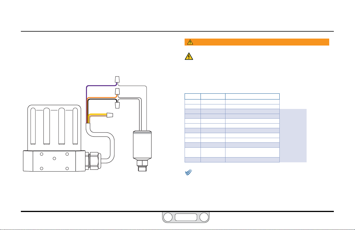
ER5000 — 96Installation Variations
NOTENOTE
BACK
Feedback Wiring Variations
Three Wire Transducer
The correct wiring for three wire transducers is shown in Figure 32.
VIOLET
ORANGE
BLACK
YELLOW
TAN
Figure 32: Three Wire Transducer Wiring
+ SUPPLY
+ OUTPUT
COMMON
TRANSDUCER
WARNING
The controller must be disconnected from the power supply before
any additional wiring or change to jumper configuration is
performed. Do not reconnect the power supply until all additional
wiring connections have been made and are properly installed.
Refer to Table 15 to verify correct wiring.
Table 15: Wiring for Three Wire Transducer
J3 Pins Wire Color Function
1 brown +setpoint input
2 red -setpoint input
3 orange +feedback input
4 yellow -feedback input
5 green -RS485 network connection
6 blue +RS485 network connection
7 violet +24V DC power
8 gray 24V return (power ground)
9 white +5V output (5 mA max.)
10 black analog signal/board ground
*11 *pink analog signal output
12 tan analog signal/board ground
Check that Jumper J6 (refer to Figure 19) is installed for
4–20 mA operation and removed for 1–5V operation. There is no jumper
on the 0–10V ER5000 models.
(active in Enhanced “F” models ONLY)
www.emerson.com/tescom
Page 97
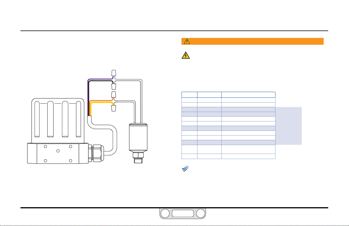
ER5000 — 97Installation Variations
NOTENOTE
BACK
Feedback Wiring Variations
Four Wire Transducer
The correct wiring for four wire transducers is shown in Figure 33.
Figure 33: Four Wire Transducer Wiring
VIOLET
BLACK
ORANGE
YELLOW
+ SUPPLY
GROUND
+ OUTPUT
COMMON
TRANSDUCER
WARNING
The controller must be disconnected from the power supply before
any additional wiring or change to jumper configuration is
performed. Do not reconnect the power supply until all additional
wiring connections have been made and are properly installed.
Refer to Table 16 to verify correct wiring.
Table 16: Wiring for Four Wire Transducer
J3 Pins Wire Color Function
1 brown +setpoint input
2 red -setpoint input
3 orange +feedback input
4 yellow -feedback input
5 green -RS485 network connection
6 blue +RS485 network connection
7 violet +24V DC power
8 gray 24V return (power ground)
9 white +5V output (5 mA max.)
10 black analog signal/board ground
*11 *pink analog signal output
12 tan analog signal/board ground
Check that Jumper J6 (refer to Figure 19) is installed for
4–20 mA operation and removed for 1–5V operation. There is no jumper
on the 0–10 Volt ER5000 models.
(active in Enhanced “F” models ONLY)
www.emerson.com/tescom
Page 98

ER5000 — 98Installation Variations
NOTENOTE
BACK
Feedback Wiring Variations
4–20 mA External Feedback, Floating Input, Feedback Signal Monitored by PC or PLC A/D Card
Figure 34 shows how the feedback signal can be monitored using
an A/D card in the PC or a PLC. The feedback signal can,
alternatively, be monitored through the USB connection between
the ER5000 and the PC by reading variable #44 (ID_FEEDBACK).
ORANGE
VIOLET
YELLOW
TAN
TRANSDUCER
Figure 34: Monitor 4–20 mA External Feedback (Floating Input)
+I IN
- I IN
+ SUPPLY
+ OUTPUT
WARNING
The controller must be disconnected from the power supply
before any additional wiring or change to jumper
configuration is performed. Do not reconnect the power
supply until all additional wiring connections have been
made and are properly installed.
Refer to Table 17 to verify correct wiring.
Table 17: Wiring for Monitoring 4–20 mA External Feedback (Floating Input)
J3 Pins Wire Color Function
1 brown +setpoint input
2 red -setpoint input
3 orange +feedback input
4 yellow -feedback input
5 green -RS485 network connection
6 blue +RS485 network connection
7 violet +24V DC power
8 gray 24V return (power ground)
9 white +5V output (5 mA max.)
10 black analog signal/board ground
PC
*11 *pink analog signal output
12 tan analog signal/board ground
Check that Jumper J6 (refer to Figure 19) is installed for
4–20 mA operation.
(active in Enhanced “F” models ONLY)
www.emerson.com/tescom
Page 99
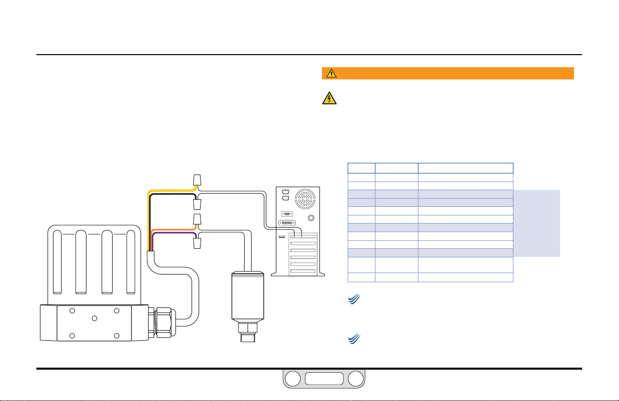
ER5000 — 99Installation Variations
NOTENOTE
NOTENOTE
BACK
Feedback Wiring Variations
4–20 mA External Feedback, Ground Referenced Input, Feedback Signal Monitored by PC or PLC A/D Card
Figure 35 show how the feedback signal can be monitored
using an A/D card in the PC or a PLC. The feedback signal can,
alternatively, be monitored through the USB connection between
the ER5000 and the PC by reading variable #44 (ID_FEEDBACK).
YELLOW
BLACK
ORANGE
VIOLET
Figure 35: Monitor 4–20 mA External Feedback (Ground Referenced Input)
+ I IN
- I IN
+ OUTPUT
+ SUPPLY
TRANSDUCER
WARNING
The controller must be disconnected from the power supply before
any additional wiring or change to jumper configuration is
performed. Do not reconnect the power supply until all additional
wiring connections have been made and are properly installed.
Refer to Table 18 to verify correct wiring.
Table 18: Wiring for Monitoring 4–20 mA External Feedback (Ground Referenced Input)
J3 Pins Wire Color Function
1 brown +setpoint input
2 red -setpoint input
3 orange +feedback input
4 yellow -feedback input
5 green -RS485 network connection
6 blue +RS485 network connection
7 violet +24V DC power
8 gray 24V return (power ground)
9 white +5V output (5 mA max.)
10 black analog signal/board ground
*11 *pink analog signal output
PC
12 tan analog signal/board ground
The wiring shown in Figure 35 is for a two wire
transducer. Refer to Figure 32 and Figure 33, respectively, for
correct wiring of three wire and four wire transducers.
Check that Jumper J6 (refer to Figure 19) is installed for
4–20 mA operation.
(active in Enhanced “F” models ONLY)
www.emerson.com/tescom
Page 100

ER5000 —
NOTENOTE
BACK
Installation Variations
Feedback Wiring Variations
Two Wire Transducer, PC or PLC A/D Card Used to Monitor Voltage Produced by the 4–20 mA External Feedback
Figure 36 shows correct wiring for applications where it is
necessary to monitor the voltage produced across the ER5000’s
internal 250Ω resistor, rather than breaking into the 4–20 mA
loop, to avoid producing ground loops.
YELLOW
TAN
ORANGE
VIOLET
+ SUPPLY
TRANSDUCER
Figure 36: Two Wire Transducer, Monitor Voltage Produced by 4–20 mA Feedback
- V IN
+V IN
+ OUTPUT
WARNING
The controller must be disconnected from the power supply before
any additional wiring or change to jumper configuration is
performed. Do not reconnect the power supply until all additional
wiring connections have been made and are properly installed.
The feedback signal can, alternatively, be monitored
through the USB connection between the ER5000 and the
PC by reading variable #44 (ID_FEEDBACK).
Refer to Table 19 for correct wiring.
Table 19: Wiring for Monitoring Voltage from 4–20 mA External Feedback,
Two Wire Transducer
J3 Pins Wire Color Function
1 brown +setpoint input
2 red -setpoint input
3 orange +feedback input
4 yellow -feedback input
5 green -RS485 network connection
6 blue +RS485 network connection
7 violet +24V DC power
8 gray 24V return (power ground)
PC
9 white +5V output (5 mA max.)
10 black analog signal/board ground
*11 *pink analog signal output
12 tan analog signal/board ground
(active in Enhanced “F” models ONLY)
Check that Jumper J6 (refer to Figure 19) is installed for
4–20 mA operation.
www.emerson.com/tescom
100
 Loading...