

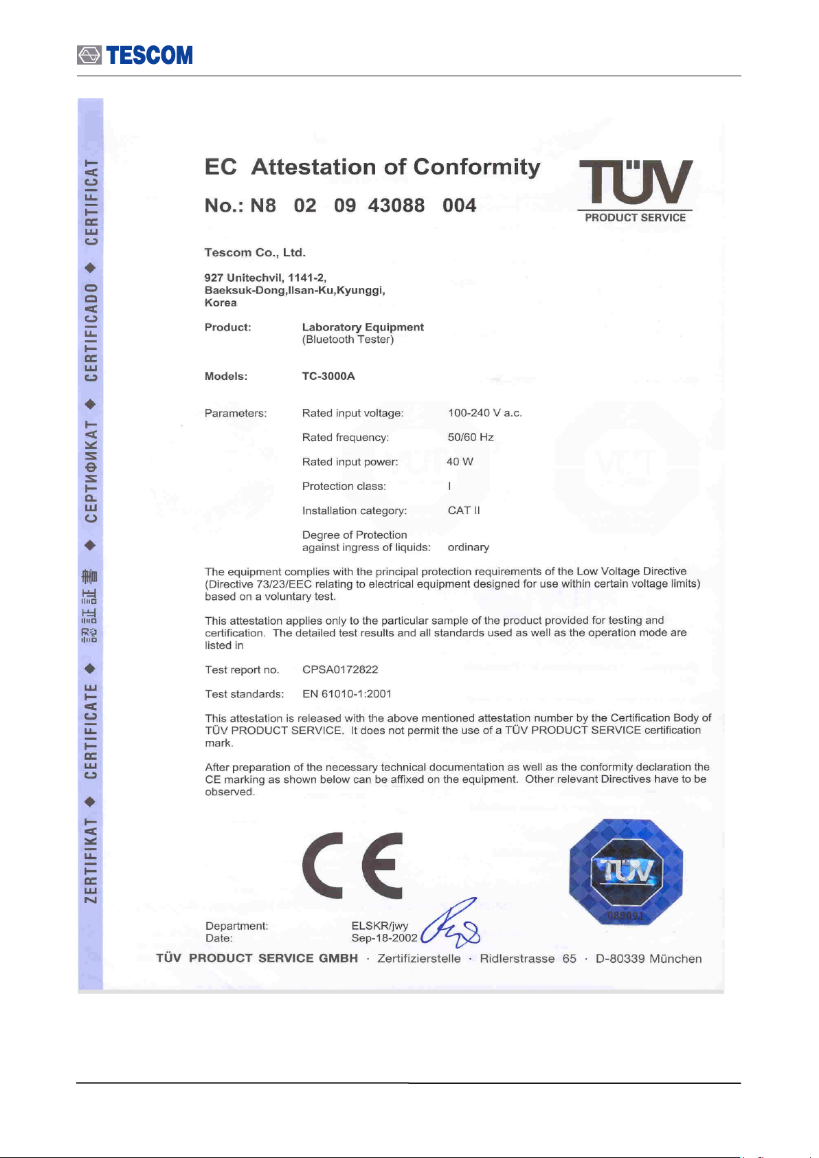
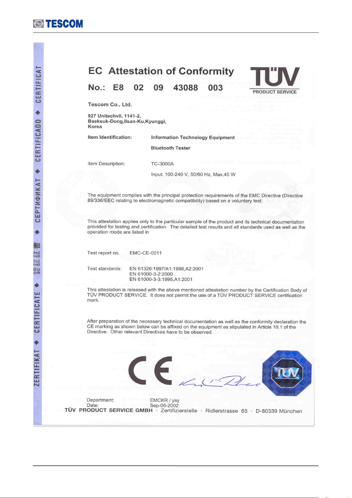
Page 1

TC-3000C Bluetooth Tester
Operating Manual
R20140925
http://www.tescom.co.kr
The information contained in this document is subject to change without prior notice.
Bluetooth is a trademark owned by Bluetooth SIG, Inc., and licensed to Tescom.
Copyright 2004 Tescom Co., Ltd., Suite 927, Unitechvil, 142, Ilsan-ro, Ilsandong-gu, Goyang-si, Gyunggi-do, Korea
Page 2

Page 3

Table of Contents
TABLE OF CONTENTS
General Information ........................................................................................................... 9
1.1 WARRANTY ....................................................................................................................................... 10
1.2 Safety Consideration .......................................................................................................................... 13
1.2.1 Injury Precautions .................................................................................................................. 13
1.2.2 Product Damage Precautions ................................................................................................ 13
1.3 Safety Symbols and Terms ................................................................................................................. 14
1.4 TESCOM Sales and Service Office .................................................................................................... 14
1.5 Manual Convention ............................................................................................................................ 14
1.6 Instruction and Key Features ............................................................................................................. 15
1.6.1 Key Features .......................................................................................................................... 15
1.7 Specification ....................................................................................................................................... 16
1.8 Connectors ......................................................................................................................................... 16
Installation ........................................................................................................................ 17
2.1 Initial Inspection .................................................................................................................................. 18
2.2 Power Requirement ............................................................................................................................ 18
2.3 Operating Environment ...................................................................................................................... 19
2.4 Carrying Handle and Caution for Moving ........................................................................................... 19
2.5 Firmware Upgrade .............................................................................................................................. 20
2.6 Cleaning, Storage and Shipment........................................................................................................ 21
2.6.1 Cleaning ................................................................................................................................. 21
2.6.2 Storage ................................................................................................................................... 21
2.6.3 Shipment ................................................................................................................................ 21
Operation .......................................................................................................................... 24
3.1 Overview ............................................................................................................................................. 25
3.1.1 TC-3000C System Architecture .............................................................................................. 25
3.1.2 Start-up Screen ...................................................................................................................... 26
3.1.3 Shutdown Screen ................................................................................................................... 26
3.1.4 Display Color Scheme ............................................................................................................ 26
3.1.5 System Information ................................................................................................................ 27
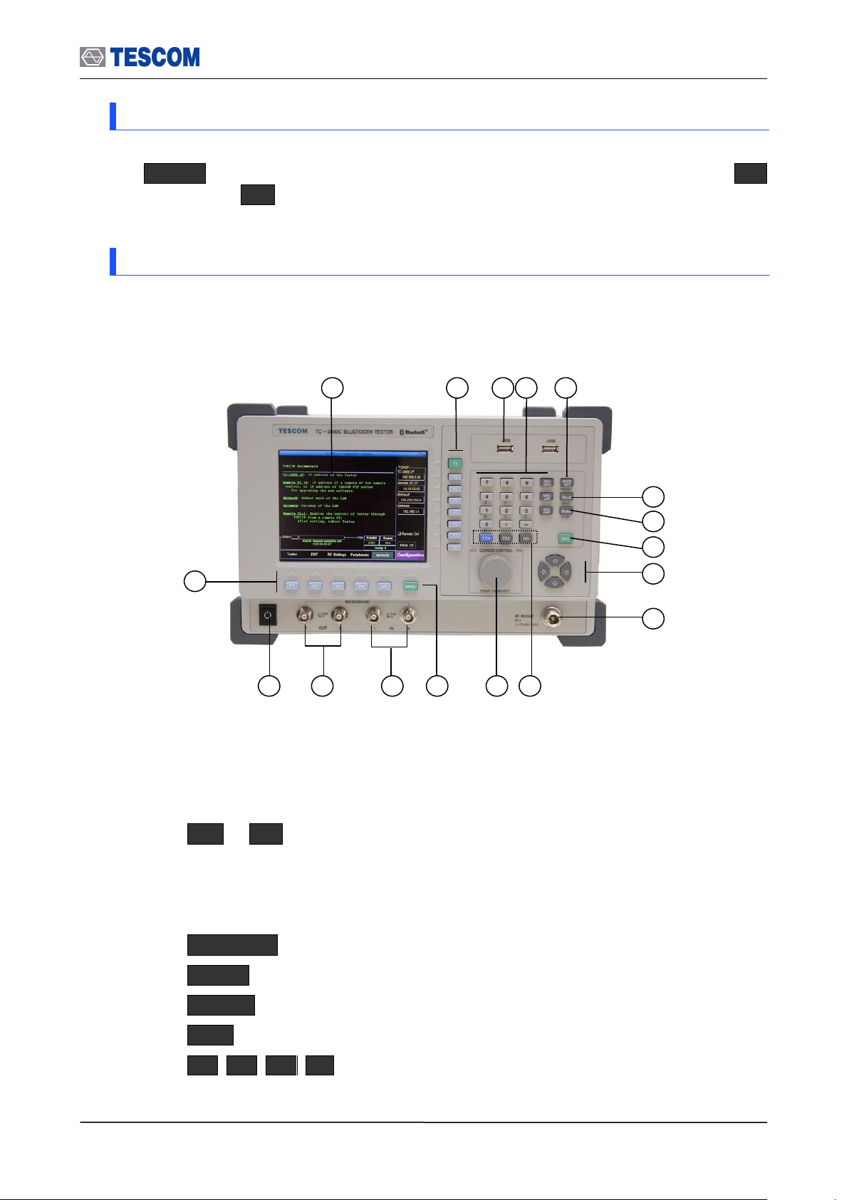
3.1.6 Front Panel View .................................................................................................................... 27
3.1.7 Rear Panel View..................................................................................................................... 29
3
Page 4

Table of Contents
3.1.8 Display Screen ....................................................................................................................... 30
3.1.9 Menu Structure ....................................................................................................................... 31
3.1.10 Access Main Functions ........................................................................................................ 32
3.1.11 Data Input and Change ........................................................................................................ 33
3.1.12 Enter and Change the Unit-of-Measure ............................................................................... 33
3.1.13 Interaction Between Screens ............................................................................................... 33
3.1.14 Tool Tips ............................................................................................................................... 33
3.1.15 Typical Test Configurations .................................................................................................. 34
3.2 Basic Operation Procedure ................................................................................................................ 35
3.2.1 Step 1. Getting Started ........................................................................................................... 35
3.3 Operation Procedure (Link Analyzer) ................................................................................................. 39
3.3.1 Step 2. Creating Connection to DUT ...................................................................................... 39
3.3.2 Step 3. Viewing the Recorded Data ....................................................................................... 41
3.4 Operation Procedure (Host Analyzer) ................................................................................................ 44
3.4.1 Step 2. Creating Connection to DUT ...................................................................................... 44
3.4.2 Step 3. Viewing the Recorded Data ....................................................................................... 47
3.5 Operation Procedure (Measurement/Measurement2) ....................................................................... 49
3.5.1 Step 3. Selecting the Measurement Screen........................................................................... 49
3.5.2 Step 4. Measuring RF Characteristics of DUT ....................................................................... 50
3.5.3 Step 5. Setting Up Test Mode and Parameters ...................................................................... 56
3.6 Operation Procedure (EDR Measurement) ........................................................................................ 57
3.6.1 Step 3. Selecting the EDR Measurement Screen .................................................................. 57
3.6.2 Step 4. Measuring EDR Characteristics of DUT .................................................................... 58
3.7 Operation Procedure (Audio Analyzer) .............................................................................................. 61
3.7.1 Step 2. Creating Connection to DUT ...................................................................................... 61
3.7.2 Step 3. Verification of Speech Loopback for Mono Headset .................................................. 63
3.7.3 Step 4. Measuring Audio Characteristics of DUT ................................................................... 64
3.8 Operation Procedure (Bluetooth Conformance Test) ......................................................................... 69
3.8.1 Step 3. Selecting the Test Cases Screen ............................................................................... 71
3.8.2 Step 4. Selecting the Test Cases and Setting Up Test Parameters ....................................... 71
3.8.3 Step 5. Running the Test Cases and Viewing the Test Results ............................................. 72
3.9 Setting up for Bluetooth LE(Low Energy) Testing .............................................................................. 73
3.10 Configuration of the TC-3000C ........................................................................................................ 74
3.10.1 Tester .................................................................................................................................... 74
3.10.2 DUT ...................................................................................................................................... 77
3.10.3 RF Settings........................................................................................................................... 79
3.10.4 Peripherals ........................................................................................................................... 79
3.10.5 Network ................................................................................................................................ 80
3.11 General Purpose Communication Analyzer ..................................................................................... 81
3.11.1 Signal Generator .................................................................................................................. 81
3.11.2 Signal Analyzer ..................................................................................................................... 82
4
Page 5

Table of Contents
3.12 Store/Recall/Preset Instrument Settings .......................................................................................... 83
3.13 Checking List for Common Problems ............................................................................................... 83
3.13.1 Unit is inoperative ................................................................................................................. 84
3.13.2 Failure of testing ................................................................................................................... 84
Performance Test ............................................................................................................. 85
4.1 General Information ............................................................................................................................ 85
4.1.1 Recommended test equipment .............................................................................................. 86
4.1.2 Calibration Cycle .................................................................................................................... 86
4.1.3 TC-3000C Initial Set Up ......................................................................................................... 87
4.2 Signal Generator ................................................................................................................................ 87
4.2.1 Frequency Accuracy ............................................................................................................... 87
4.2.2 I/Q modulation calibration ...................................................................................................... 88
4.2.3 PLL phase noise ..................................................................................................................... 89
4.2.4 FM accuracy ........................................................................................................................... 90
4.2.5 Output level accuracy test ...................................................................................................... 91
4.3 Testing Receiver ................................................................................................................................. 92
4.3.1 Power measurement accuracy ............................................................................................... 92
4.3.2 Maximum sensitivity ............................................................................................................... 94
4.3.3 Gain Roll-off ........................................................................................................................... 95
Programming Guide ........................................................................................................ 96
5.1 Introduction ......................................................................................................................................... 97
5.2 Getting Started .................................................................................................................................... 97
5.2.1 Settings for Ethernet(Host) remote control using DLL ........................................................... 99
5.2.2 Settings for USB(Host Controller) remote control using DLL ................................................. 99
5.2.3 Settings for RS-232C(Host Controller) remote control using DLL ....................................... 100
5.2.4 Settings for the RS-232C(Host) remote control without using DLL ..................................... 100
5.2.5 Preparing for your application using DLL ............................................................................. 101
5.3 Reference Guide using RS-232C commands .................................................................................. 101
5.3.1 Configuration Command ...................................................................................................... 101
5.3.2 Access Command ................................................................................................................ 109
5.3.3 RF Test Cases Command ..................................................................................................... 110
5.3.4 Output Power(OP) ................................................................................................................. 110
5.3.5 Power Density(PD) ................................................................................................................ 111
5.3.6 Power Control(PC) ................................................................................................................ 112
5.3.7 Enhances Power Control(EPC)............................................................................................. 113
5.3.8 Frequency Range(FR) .......................................................................................................... 115
5.3.9 20dB Bandwidth(20BW) ........................................................................................................ 116
5.3.10 Adjacent Channel Power(ACP) ........................................................................................... 117
5.3.11 Modulation Characteristics(MOD) ....................................................................................... 118
5.3.12 Initial Carrier Frequency Tolerance(ICFT) ........................................................................... 119
5
Page 6

Table of Contents
5.3.13 Carrier Frequency Drift(CFD) ............................................................................................. 121
5.3.14 Single Slot Sensitivity(SS) .................................................................................................. 122
5.3.15 Multi Slot Sensitivity(SM) ................................................................................................... 123
5.3.16 Maximum Input Level(ML) .................................................................................................. 125
5.3.17 Quick Test(OPMOD) .......................................................................................................... 126
5.3.18 BER & FER ........................................................................................................................ 128
5.3.19 EDR Relative Transmitter Power(ETP) .............................................................................. 130
5.3.20 EDR Carrier Frequency Stability & Modulation Accuracy(EFSMA) ................................... 132
5.3.21 EDR Differential Phase Encoding(EDPE) .......................................................................... 135
5.3.22 EDR In-band Spurious Emission(ETP) .............................................................................. 136
5.3.23 EDR Sensitivity(ES) ........................................................................................................... 137
5.3.24 EDR BER Floor Performance(EBP) ................................................................................... 139
5.3.25 EDR Maximum Input Level(EML)....................................................................................... 140
5.3.26 Audio Test Command ......................................................................................................... 142
5.4 Example using command ................................................................................................................. 147
5.5 Flow Chart for RS-232C Commands................................................................................................ 148
5.6 Sample Code(VC++) for RS-232C remote control ........................................................................... 152
5.7 Reference Guide for using DLL ........................................................................................................ 157
5.7.1 General Function .................................................................................................................. 157
5.7.2 Tester Configuration ............................................................................................................. 157
5.7.3 DUT Configuration................................................................................................................ 174
5.7.4 Access Fucntions ................................................................................................................. 186
5.7.5 Security Fucntions ................................................................................................................ 188
5.7.6 Profile Fucntions .................................................................................................................. 188
5.7.7 Audio Fucntions .................................................................................................................... 190
5.7.8 Signal Generator .................................................................................................................. 191
5.7.9 RF Test Cases ...................................................................................................................... 192
5.7.10 Measurement Functions ..................................................................................................... 198
5.8 Flow Chart for DLL functions ............................................................................................................ 202
5.9 Example using DLL .......................................................................................................................... 205
5.9.1 Measuring Output Power ..................................................................................................... 205
Appendices .................................................................................................................... 209
Appendix A. Specification ....................................................................................................................... 210
5.1.1 RF SOURCE ........................................................................................................................ 210
5.1.2 RF ANALYZER ..................................................................................................................... 210
5.1.3 SPECTRUM ANALYZER ...................................................................................................... 211
5.1.4 FM MODULATION ANALYZER ............................................................................................. 211
5.1.5 POWER-TIME ....................................................................................................................... 211
5.1.6 POWER-CHANNEL (BT Mode) ............................................................................................ 211
5.1.7 RX BER TEST (BT Mode) ..................................................................................................... 211
5.1.8 I-Q CONSTELLATION (EDR BT Mode) ................................................................................ 211
6
Page 7

Table of Contents
5.1.9 TX BER TEST (BT Mode) ..................................................................................................... 211
5.1.10 DEVM (Differential Error Vector Magnitude) ....................................................................... 211
5.1.11 FREQUENCY REFERENCE .............................................................................................. 212
5.1.12 FRONT PANEL .................................................................................................................. 212
5.1.13 REAR PANEL ..................................................................................................................... 212
5.1.14 MISCELLANEOUS ............................................................................................................. 212
Appendix B. RF Test Cases of the TC-3000C ........................................................................................ 213
5.2.1 Output Power (TRM/CA/01/C) ............................................................................................. 213
5.2.2 Power Density (TRM/CA/02/C) ............................................................................................ 214
5.2.3 Power Control (TRM/CA/03/C)............................................................................................. 216
5.2.4 TX Output Spectrum – Frequency range (TRM/CA/04/C) ................................................... 218
5.2.5 TX Output Spectrum – 20 dB Bandwidth (TRM/CA/05/C) ................................................... 220
5.2.6 TX Output Spectrum – Adjacent channel power (TRM/CA/06/C) ........................................ 222
5.2.7 Modulation Characteristics (TRM/CA/07/C) ......................................................................... 224
5.2.8 Initial Carrier Frequency Tolerance (TRM/CA/08/C) ............................................................ 226
5.2.9 Carrier Frequency Drift (TRM/CA/09/C) ............................................................................... 227
5.2.10 EDR Relative Transmit Power (TRM/CA/10/C).................................................................. 229
5.2.11 EDR Carrier Frequency Stability and Modulation Accuracy (TRM/CA/11/C) ..................... 231
5.2.12 EDR Differential Phase Encoding (TRM/CA/12/C) ............................................................ 233
5.2.13 EDR In-band Spurious Emissions (TRM/CA/13/C) ............................................................ 234
5.2.14 Sensitivity – single slot packets (RCV/CA/01/C) ................................................................ 236
5.2.15 Sensitivity - multi-slot packets (RCV/CA/02/C) .................................................................. 238
5.2.16 Maximum Input Level (RCV/CA/06/C) ............................................................................... 240
5.2.17 EDR Sensitivity (RCV/CA/07/C) ......................................................................................... 241
5.2.18 EDR BER Floor Performance (RCV/CA/08/C) ................................................................... 243
5.2.19 EDR Maximum Input Level (RCV/CA/10/C) ....................................................................... 244
5.2.20 List of abbreviations ........................................................................................................... 246
5.2.21 References ......................................................................................................................... 246
Appendix C. The list of Save/Recall parameters .................................................................................... 247
7
Page 8

Table of Contents
List of Figures
[Figure 1] Carrying Handle .............................................................................................................. 19
[Figure 2] Front Panel View ............................................................................................................. 27
[Figure 3] Rear Panel View ............................................................................................................. 29
[Figure 4] Typical Test Configurations ............................................................................................. 34
[Figure 5] Carrier frequency accuracy test ...................................................................................... 87
[Figure 6] I/Q modulation calibration test ........................................................................................ 88
[Figure 7] PLL phase noise test....................................................................................................... 89
[Figure 8] FM accuracy test ............................................................................................................. 90
[Figure 9] Output level accuracy test............................................................................................... 91
[Figure 10] Power measurement accuracy test .............................................................................. 92
[Figure 11] Maximum sensitivity test ............................................................................................... 94
[Figure 12] Gain Roll-off test ........................................................................................................... 95
List of Tables
[Table 1] Accessory List ................................................................................................................... 18
[Table 2] Power Requirement .......................................................................................................... 18
[Table 3] Access Main Functions ..................................................................................................... 32
[Table 4] Test Parameters Refer to DUT in Configuration. .............................................................. 40
[Table 5] Pattern Example ............................................................................................................... 81
8
Page 9

This chapter covers the instrument warranty, specifications, key features, and
safety consideration.
Chapter
1
General Information
Page 10

1.1 WARRANTY
1.1 WARRANTY
TESCOM warrants that this product is free from defects in terms of materials and
workmanship for a period of one (1) year from the date of shipment. During the warranty
period, TESCOM will -- at its discretion -- either repair or replace products that prove to be
defective.
For the warranty service or repair, the Customer must notify TESCOM of the defect before
the expiration of the warranty period and make suitable arrangements for the performance
of service. The Customer shall be responsible for packaging and shipping the defective
product to the service center designated by TESCOM. The Customer shall prepay the
shipping charge to a TESCOM designated service center, and TESCOM shall pay the
shipping charge to return the product to the Customer. In case the Customer is located
outside of Korea, the Customer is responsible for all shipping charges including freight,
taxes, and any other charge if the product is returned for service to TESCOM.
LIMITATION OF WARRANTY
The foregoing warranty shall not apply to defects resulting from improper or inadequate
malignance by the Buyer, Buyer-supplied software or interfacing, unauthorized modification
or misuse, accident, or abnormal conditions of operation.
TESCOM`s responsibility to repair or replace defective products is the sole and exclusive
remedy provided to the Customer in case of breach of this warranty. TESCOM will not be
liable for any indirect, special, incidental, or consequential damages regardless of whether
TESCOM served advance notice of the possibility of such damages.
10
Page 11
1.1 WARRANTY
11
Page 12
1.1 WARRANTY
12
Page 13

1.2 Safety Consideration
1.2 Safety Consideration
Review the following safety precautions to avoid injury and prevent damage to this product
or any product connected to it:
1.2.1 Injury Precautions
Use the Appropriate Power Cord
To avoid fire hazard, use only the power cord specified for this product.
Avoid Electric Overload
To avoid electric shock or fire hazard, do not apply voltage beyond the specified range
to a terminal.
Ground the Product
This product is grounded through the grounding conductor of the power cord. In case no
ground is available at the power outlet, providing a separate grounding path to the
instrument is recommended by connecting wire between the instrument ground terminal
and earth ground to avoid electric shock or instrument damage. Before making
connections to the input or output terminals of the product, make sure that the product is
properly grounded.
Do Not Operate Without Covers
To avoid electric shock or product damage, do not operate this product with the
protective covers removed.
Do Not Operate in Wet/Damp Conditions
To avoid injury or fire hazard, do not operate this product in wet or damp conditions.
Do Not Use in a Manner Other than That Specified by the Manufacturer
1.2.2 Product Damage Precautions
Use Appropriate Power Source
Do not operate this product using a power source that applies more than the specified
voltage. Main supply voltage fluctuations should not exceed 10% of the nominal
voltage.
Provide Proper Ventilation
To prevent product overheating, provide proper ventilation.
Do Not Operate in case of Suspected Failures
If you think there is damage to this product, have it inspected by qualified service
personnel.
Environmental Conditions
Refrain from using this equipment in a place subject to considerable vibration, direct
sunlight, outdoors, and where the ground is not level. Likewise, do not use it where the
ambient temperature is beyond the range of 5 C - 40 C and altitude is more than
2000 m. The maximum relative humidity is 80 % for temperatures up to 31 C,
decreasing linearity of up to 50%, and relative humidity at 40 C, and Over voltage
Installation Category II for the main supply (Pollution Degree 2).
Shut down System
Do not power switch off by compulsion, to avoid injury or damage the internal host PC.
13
Page 14
1.3 Safety Symbols and Terms
WARRING / CAUTION
Indicates earth
(ground) terminal
Power ON
Power OFF
In order to power off safely, press Menu select “Quit” press “Yes” and then
do power switch off.
1.3 Safety Symbols and Terms
These terms may appear in this manual.
WARNING: Warning statements describe the conditions or practices that could result in
injury or loss of life.
CAUTION: Caution statements describe the conditions or practices that could result in
damage to this product or other property.
Symbols on the Product: The following symbols may appear on the product:
1.4 TESCOM Sales and Service Office
If you have difficulty with the product, call or write to our Technical Support specialists at:
TESCOM Company Limited
# 927 Unitechvil., 142, Ilsan-ro, Ilsandong-gu, Goyang-si, Gyunggi-do, Korea [ZIP 410-722]
TEL.: 82-31-920-6601 FAX: 82-31-920-6607
Email: tescom-sales@tescom.org
http://www.tescom.co.kr
1.5 Manual Convention
[ ] This indicates menus following notational conventions.
Keypad buttons are indicated with the symbol. ex) FCN
key on the front is indicated as ENT.
14
Page 15

1.6 Instruction and Key Features
1.6 Instruction and Key Features
TESCOM TC-3000C Bluetooth Tester eliminates the need for several costly testers by
combining key RF and Protocol test & measurement functions in one convenient box.
Designed for a wide range of applications in R&D, manufacturing, QA and service, this
feature-packed powerful instrument is simple to use, lightweight and portable, and may be
operated with all standard AC voltages. In addition to Bluetooth testing applications, TC3000C may be used for non-Bluetooth RF testing along the 2.4 GHz ISM band.
1.6.1 Key Features
Bluetooth V1.1/V1.2/V2.0/V3.0/V4.0 Specification Compliant
RF, Audio, and Protocol Combination Tester
Bluetooth Conformance Test
Supports Audio (SCO Link) Functional Testing (3000-10)
Bluetooth RF and Baseband Measurement Functions (3000-20)
Basic Bluetooth Protocol Analyzer Functions
- Supports Master and Slave modes
- Link test in Pico-net
- Packet information in Baseband, LMP, HCI, SDP, RFCOMM, and Profile
- Direct HCI command execution from the screen
Bluetooth EDR testing (3000-40)
Bluetooth LE testing (3000-50)
Utility digital signal generator
User definable Baseband IN/OUT ports for real time signal monitoring, external
modulation, audio source and audio analyzer
Device HCI Interface Options: USB and RS-232C (UART, BCSP)
Remote Operation: TCP/IP (LAN) and RS-232C
Easy S/W Upgrades through USB
Listed on the Bluetooth Qualified Products List (QPL) as a Development Tool
CE Compliant: EN61010-2001, EN61326,A2:2001, EN61000-3-2, 2000, EN61000-
3-3,A1:2001
15
Page 16

1.7 Specification
Connector
Specification
RS-232C
Working Voltage: 100V
Dielectric Withstanding Voltage: 300V
N Type Connector
Impedance: 50 ohm
Voltage Rating: 250 Vpeak
Dielectric Withstanding Voltage: 750 Vrms
BNC Connector
Impedance: 50 ohm
Voltage: 1Vpk
1.7 Specification
Specifications are listed in Appendix A.
1.8 Connectors
This section contains reference information for TC-3000C’s connectors.
16
Page 17

This section provides the information needed to install the TC-3000C Bluetooth Tester,
including information pertinent to initial inspection, power requirements, environment,
upgrade, storage, and shipment.
Chapter
2
Installation
Page 18
2.1 Initial Inspection
No.
Part Number
Name
Specification
Qty.
1
3407-0004
Adaptor
N(m) to BNC(m)
1
2
4003-0012
RS-232C Cable
DB9(s) to DB9(s) cable, 2 m
1
3
4006-0004
RF Cable
N(m) to N(m) cable, 1 m
1
4
4007-0001
RF Cable
BNC(m) to BNC(m) cable, 1 m
2 5 4008-0012
LAN Cable
STP, Cross, RJ45 cable, 2 m
1
6
4008-0016
USB Cable
USB A (p) to USB A (s) cable, 1.8 m
1
7
E92050A
Antenna
Sleeve 2.4 GHz
1
8
E99912A
Attenuator
10 dB, 0.5W, N Type
1
9 Power Cord
2 m
1
10
Operating Manual
1
Characteristic
Requirement
Input voltage
100 VAC - 240 VAC
Frequency
50/60 Hz
Power Consumption
Less than 40 watt
WARNING
To avoid hazardous electrical shock, do not perform electrical tests when there are
signs of shipping damage to the equipment.
2.1 Initial Inspection
This section provides information for verifying proper shipment of the TC-3000C Bluetooth
Tester.
Product Condition and Accessory Check
1. Upon receipt of the TC-3000C Bluetooth Tester, check for damage that could
have occurred during shipment.
2. Check whether you have received all the standard accessories supplied with
TC-3000C as listed in table below.
[Table 1] Accessory List
2.2 Power Requirement
This Tester is a portable instrument, requiring no physical installation other than connection
to a power source.
[Table 2] Power Requirement
18
Page 19
2.3 Operating Environment
WARNING
If AC power is beyond the range of operation, the equipment may malfunction or
sustain permanent damage. Main supply voltage fluctuations should not exceed 10%
of the nominal voltage.
Bench-top viewing position
Carrying position
2.3 Operating Environment
Refrain from using this equipment in a place subject to considerable vibration, direct
sunlight, outdoor, and where the ground is not level. Likewise, do not use it in areas where
the ambient temperature is beyond the range of 5 C ~ 40 C, and altitude is more than
2000 m.
The maximum relative humidity is 80 % for temperatures up to 31 C, decreasing linearity
to 50% relative humidity at 40 C. (Over voltage Installation Category II for main supply;
Pollution Degree 2)
The storage temperature range for this equipment is –20 C ~ 70 C, when this equipment
is not used for a long period of time, store in a dry place away from direct sunlight by
covering with vinyl or placing in a cardboard box.
2.4 Carrying Handle and Caution for Moving
Carrying Handle Adjustment
To adjust the handle position, push both caps covering the rotary joints on each side. .
Then, rotate the handle to the desired position.
[Figure 1] Carrying Handle
Caution for moving
When you are moving the TC-3000C, please use USB cable protector on rear panel. If not,
USB cable between host and host controller could be damaged.
19
Page 20
2.5 Firmware Upgrade
i
Get SBC s/w from:
Please never downgrade to v2.30 or earlier unless you have BT option
Remote FTP
USB Memory
Cancel
i
Connect an USB Memory to USB Port;
And Please wait 5 seconds before pressing OK
Cancel
OK
Upgrading DONE. Reboot to activate
i
Cancel
OK
2.5 Firmware Upgrade
TC-3000C Firmware can be upgraded easily using USB memory. You can download the
upgrade data file from Tescom website.
Upgrade from the USB Memory
1. Download Firmware files from Tescom website.
2. Unzip the firmware files.
3. When you unzip file is created.
4. Save the “upgrade3000c.tgz” files to the USB Memory
5. Plug in the USB Memory at front panel USB port.
6. Press Menu select “Configuration” from the pop-up menu on the screen
M5 (Network” )
7. Move “more 3/3” using the F8 key and press F3 ( “Upgrade S/W” )
8. Select “USB Memory” from the pop-up menu and select “ok” button.
9. When Upgrade is completed successfully, select “ok” button
10. When the TC TC-3000C is turned off, turn off and on the rear panel power switch.
11. Turn on the front panel SW switch.
20
Page 21

2.6 Cleaning, Storage and Shipment
NOTE
If download is failed, please check following cases.
[Case 1]: The connection cable between Host and Host Controller on rear panel
must be a USB cable.
[Case 2]: USB recognition time is different depends on USB Memory, so upgrade
should be started after recognition is finished. Usually, you can check it using the
LED lamp of USB memory.
[Case 3]: Even if you cannot upgrade using above cases, perform following steps
for Emergency Upgrade.
1. Turn off the TC3000C.
2. Locate the “DOWNLOAD/NORMAL switch” at rear panel and set it to
DOWNLOAD.
3. Turn on the TC-3000C and repeat the upgrade procedure above.
4. When the upgrade is completed, turn off TC-3000C and return the download
switch to NORMAL position.
5. Turn on TC-3000C
2.6 Cleaning, Storage and Shipment
2.6.1 Cleaning
Periodically wipe the case with a damp cloth mild detergent; do not use abrasives or
solvents.
Keep the power supply free of dust. Clean the power inlet regularly. If dust accumulates
around the power pins, there is a risk of fire.
Clean the input terminal as follows:
1) Turn the TC-3000C off and remove all test leads.
2) Shake out any dirt that be in the terminals.
3) Soak a new swab with alcohol and work around in each terminal.
2.6.2 Storage
The storage temperature range for this equipment is –20 C to 70 C. When this
equipment is not used for a long period of time, covered with vinyl or placed in a
cardboard box, store it in a dry place away from direct sunlight.
2.6.3 Shipment
When shipping this equipment, use the original packing materials. If they are not available,
pack the equipment as follows:
1) Wrap this equipment, in appropriate shock absorbing materials and put it in a
corrugated cardboard box at least 5 mm thick. (If shipping to a TESCOM Service
Office, attach a tag indicating the type of service required, return address, model
number and full serial number.)
2) Wrap its accessories separately in the same shock absorbing material and put
21
Page 22

2.6 Cleaning, Storage and Shipment
CAUTION
Never use any chemical cleaner other than alcohol for the maintenance of this
equipment. Organic solvent such as benzene, toluene or acetone may spoil the
plastic parts of this equipment
them in the same corrugated cardboard box together with this equipment.
3) Fasten the corrugated cardboard box with packing strings.
4) Mark the shipping container FRAGILE to assume careful handing.
22
Page 23

2.6 Cleaning, Storage and Shipment
23
Page 24

This section describes the basic concepts and details of operating TC-3000C Bluetooth
Tester. Understanding the basic concepts of TC-3000C helps you use it effectively. Operation
Overview quickly shows you how TC-3000C is organized and gives some very general
operating instructions. After you read Operating Overview you can use Operation Procedure
for detail information.
Chapter
3
Operation
Page 25
3.1 Overview
Note
HOST and HOST controller must be connected to each other by USB except
for a case when TC-3000C uses an external HOST or HOST controller.
3.1 Overview
The Overview section contains illustrations of the display, the front and rear panels, and the
menu system. These illustrations will help you understand and operate the TC-3000C.
3.1.1 TC-3000C System Architecture
TC-3000C is made up of two main blocks,
a RF/DSP module and host CPU module,
and is connected by a host controller
interface (HCI) that is identical to
Bluetooth system architecture. The
RF/DSP module provides an RF interface
to DUT, performs physical measurements
and manages the Bluetooth link. The
internal host CPU (PC), which runs on
Linux platform, takes care of user
interface (UI) functions including display,
key input and I/O controls for RS-232C,
USB, LAN and other standard peripheral
devices. The adoption of open OS
minimizes unnecessary constraints on
system optimization. This simple, elegant
system architecture takes advantage of
both power of DSP and convenience of
PC.
25
Page 26
3.1 Overview
Note
When TC-3000C is turned on, the instrument does not return to the power-off
condition –except for the Test Cases parameters which were saved - but
recalls the settings from the most recently saved memory location (STORE
Number).
TC-3000C
Bluetooth Tester
S/N:
S/W Options:
OK
3.1.2 Start-up Screen
When power on, the start-up screen will be displayed after booting process and will change
to initial screen 10 seconds later. Pressing any key will change the display immediately.
3.1.3 Shutdown Screen
In order to power off, press Menu select “Quit” from the pop-up menu on the screen
press “Yes” . Or you can turn off the TC-3000C using the front panel soft switch
3.1.4 Display Color Scheme
The display color option allows you to change the display color scheme for the front panel
display. To change the color scheme, press Menu select “Configuration” from the popup menu on the screen M4 ( “Peripherals” ) F5 ( “color scheme” ) select the
color scheme which you want to use.
26
Page 27
3.1 Overview
1 2 3 4 5
6 7 8 9 10
17
13
14
15
11
12
16
3.1.5 System Information
In order to check system information of TC-3000C,
press Menu select “Configuration” from the pop-up menu on the screen M4
( “Peripherals” ) F8 ( “System Info” ) Verify: Serial Number, Version, Core Version,
DSP Version, FPGA Version, Software Options
3.1.6 Front Panel View
The front panel controls and connector are illustrated below; and the detailed descriptions
are as follows:
[Figure 2] Front Panel View
① Color Graphic LCD
The LCD display color is configured in the Peripherals of the Configuration
screen.
② F1 ~ F8 : Soft keys. Soft keys select submenus.
③ USB port : It is used for testing the BT USB Dongle, storing the test result,
capturing screen or system upgrade.
④ Data Input keypad. Provides the means for entering data.
⑤ INCR SET : Defining data increasing step. The default value is 1.
⑥ Recall : Recall stored data.
⑦ Marker : Enable a line-shaped marker on the Measurement screen to activate.
⑧ ENT : It is used to enter your chosen function or accept input.
⑨ : Cursor movement.
27
Page 28
3.1 Overview
Note
Purpose of the front panel USB port
① for Bluetooth USB Dongle testing
② for copying test case report file, screen capture or firmware upgrade
③ When the USB memory stick is used, it should be used after the device is
recognized (2 ~ 3 sec).
Some USB memories could not be recognized. (For normal operation, the
USB device should support LINUX OS and composed only one drive.)
④ If the USB memory were removed during Reading/Writing operation, the
TC3000C could be shut down. Previous operation should be finished before
doing next operation.
⑩ RF IN/OUT Port: N type RF connector
⑪ BS : Back space key
ESC : Return to the previous state.
FCN : Access second functions
⑫ Rotary knob: Move cursor. Push to accept data or function such as ENT .
⑬ MENU : Main menu key. When this key is pressed the pop-up menu is
displayed on the center of screen. This menu presents seven options including
main functions.
⑭ Baseband Input Ports: I-Rx, Q-Rx, I-Tx, Q-Tx, Rx-bit, Tx-bit. For using
external baseband signals. It is used for stereo headset test using A2DP
⑮ Baseband OUT ports: Rx (I, Q), Tx (I, Q), Demodulation, Modulation, RX and
TX bit streams, RX and TX Clocks. It is used for stereo headset test using A2DP.
16
○
Soft switch.
17
○
M1 thru M8 : Soft keys. Soft keys select test screen.
Second Functions (Blue Label Functions)
Additional functions available by FCN key.
FCN INCR SET (= PRESET): Preset the instrument to a predefined state.
FCN Recall (= SAVE): Store the current instrument settings into memory (1 to 7)
FCN Marker (= STEP): Defining moving step of the line markers in the measurement
screens.
FCN 0 , 1 , 2 , 3 , 4 , 5 (= A,B,C,D,E,F) : It is used when you enter
hexadecimal data.
FCN ESC (=Screenshot): Capturing current displayed screen.
28
Page 29
3.1 Overview
1 3 2
4
6
9
12
7
5
11
10
8
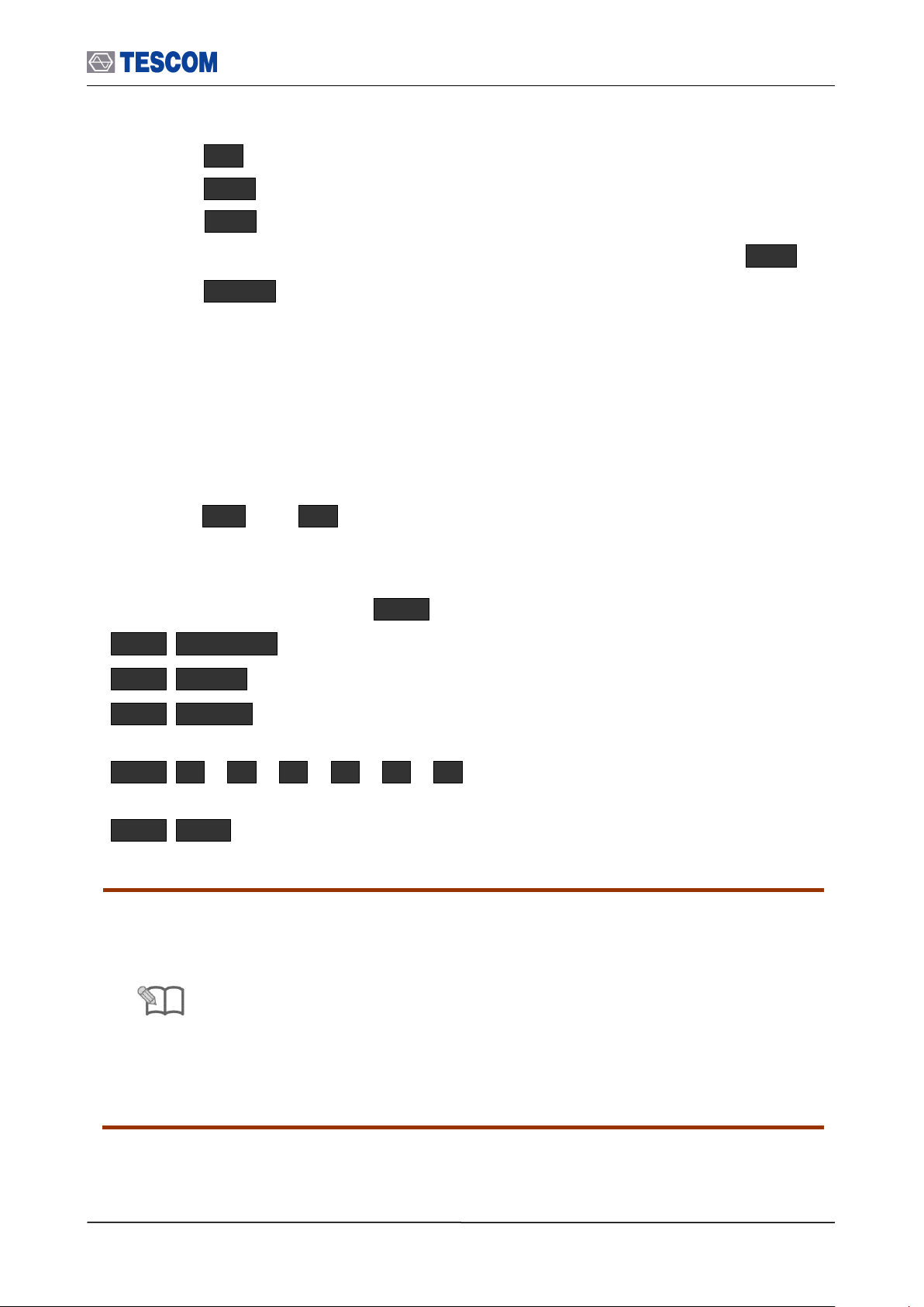
3.1.7 Rear Panel View
The Rear panel connectors are illustrated below; detailed descriptions are as follows:
[Figure 3] Rear Panel View
① RS-232C: This port is a serial port to Host Controller.
② RS2/UART2/BCSP2: This port is a RS2/UART2/BCSP2/ port to Host.
③ EXT 10 MHz: This port is an external 10 MHz reference signal.
④ Power switch
⑤ AC Power Input: 100-240 VAC, 50/60 Hz
⑥ Emergency Firmware download switch: For upgrading firmware when Host
Controller doesn’t boot. This switch is not used after normal firmware
upgrading
⑦ Monitor connector: For using an external monitor.
⑧ RS-232C/UART 1/BCSP1 connector: This port is the first serial port to Host.
It can be used for the remote control.
⑨ LAN connector
⑩ USB : This port is a USB port to Host.
⑪ USB : This port is a USB port to Host.
⑫ USB : This port is a USB port to Host controller. It is for the remote control
with DLL.
29
Page 30
3.1 Overview
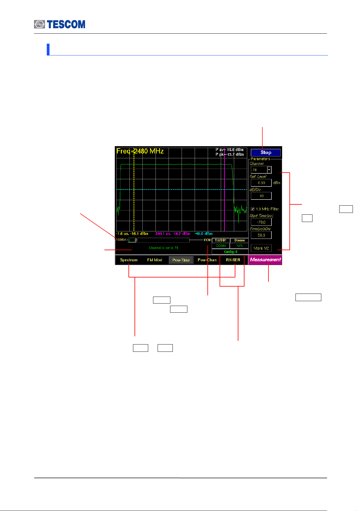
Submenus related
to soft keys, F1 ~
F8
Status window: Some
messages are displayed
to help you to understand
current status easily.
FCN Key Indicator:
When FCN key is pressed
the indicator is brightened.
Test progress
Indicator:
This progressive bar
indicates the status of
test proceeding.
Screen menus related to
soft keys, M1 ~ M5
Main function menu related
to hard key, MENU . This
menu always displays the
selected function.
Start/Stop: When this menu is pressed
the tests will run once. When pressed
again while the tests are running, the
testing will stop.
Link Status Indicator: It presents link
status, a HCI type that is connected to
Host and the number of current
configuration.
3.1.8 Display Screen
30
Page 31

3.1 Overview
Link Analyzer
Measurement
Test Cases
Audio
Configuration
Link
Pkt Info
LMP
HCI
Baseband
Pressing MENU key
Spectrum
FM Mod
Pow-Time
Pow-Chan
RX-BER
RF
SCO Link
Audio Test
Audio Spec
Audio Sweep
FSK
Tester
DUT
RF Settings
Peripherals
Network
Submenus
Submenus
Submenus
Submenus
Submenus
Submenus
Host Analyzer
Link
L2CAP
RFCOMM
(AVDTP)
SDP
PROFILE
(AVRCP)
Submenus
Measure(EDR)
BER Search
Submenus
Measurement2
Constel
TX-BER
DEVM
Submenus
SigGen
3.1.9 Menu Structure
TC-3000C has tree-like structure. 9 main functions have subcategories (screen menus)
respectively. Each subcategory has several submenus for setting up test parameters.
31
Page 32

3.1 Overview
Main Function ( MENU key)
Test Screen ( MI ~ M5 )
Link Analyzer
Basic Actions – Discover/Connect/Discoverable
Tx/Rx Packet Information – Inquiry/Page/Channel
LMP Messages
HCI Commands / Events
Baseband Packets Analysis
Host Analyzer
Basic Actions – Discover/Connect/Pairable
L2CAP
RFCOMM (AVDTP)
SDP
PROFILE (AVRCP)
Measurement
Spectrum
FM Modulation
Power vs. Time
Power vs. Channel
RX-Bit Error Rate (RX-BER)
Measurement2
BER Search
Measurement(EDR)
Constellation
TX-BER
DEVM
Test Cases
RF (13 test cases, “Quick Test Function”, BER/FER, 7
EDR test cases for EDR option )
RF (7 test cases for BT LE option)
Audio
SCO Link / SCO Loopback Test
Audio Test
Audio Spectrum
Audio Sweep
RF Signal Generator
FSK Modulation
Configuration
Tester
DUT
RF Settings
Peripherals
Network
3.1.10 Access Main Functions
The TC-3000C Bluetooth Tester contains key RF and protocol test & measurement functions
in one package. Controls for these functions are arranged on several screens. The Link
Analyzer, Host Analyzer, Measurement, EDR Measurement, Audio Test, Signal Generator,
Test Cases, and Configuration screens contain most of the functions and fields associated
with testing Bluetooth receivers and transmitters. The screens are accessed using the
MENU key and soft keys, M1 ~ M5 .
[Table 3] Access Main Functions
32
Page 33

3.1 Overview
Field
Unit
Frequency
MHz, kHz, GHz
Power
dBm, uW, mW
3.1.11 Data Input and Change
1) Press soft key related to the desired input menu.
2) The cursor indicates data input position.
3) Change value with Rotary Knob or keys. Or enter data with Key Pad.
4) Push Rotary Knob or ENT to confirm the inputted value.
5) BS (Back Space) key be used, if necessary.
6) Many menus display a list of choices when selected. Select a new setting from the
list.
3.1.12 Enter and Change the Unit-of-Measure
When the unit is implied, the current unit is used. For example; if the present Reference
Level is 0dBm, and you want to change it to 10 dBm, you would enter this sequence:
1 0 ENT
When the unit is specified, the units change to whatever you specify. For example; if the
present Reference Level is 0 dBm, and you want to change it to 10 mW, you would
enter this sequence:
1 0 mW
To change the present unit-of-measure, position the cursor in front of current unit and
press the key labeled with the desired unit
Available units:
3.1.13 Interaction Between Screens
Some menus operate globally; changing the setting in any screen automatically changes
that setting in all screens where it is available. Test Mode is an example of this menu type.
Ex) Configuration: DUT: Test Mode: Transmitter MEASUREMENT: Spectrum: Test
Mode: Transmitter MEASUREMENT: FM Modul.: Test Mode: Transmitter
MEASUREMENT: Pow-Time: Test Mode: Transmitter MEASUREMENT: PowChan: Test Mode: Transmitter Link Analyzer: LINK: Test Mode: Transmitter
3.1.14 Tool Tips
Throughout the GUI, tool tips provide useful information.
To display a tool tip, press FCN and Soft keys related to a menu. The tool tip
disappears when any key is pressed.
33
Page 34

3.1 Overview
TC-59XX Shield Box
Probe/ Connector
HCI
Set Test Mode
TC-59XX Shield Box
Set Test Mode
RF Coupler
HCI
HCI
Set Test Mode
TC506X
TEM Cell
3.1.15 Typical Test Configurations
Diagrams below are an ideal set up for testing Bluetooth devices. Since most
Bluetooth devices use sealed antenna due to their size, final RF tests must be done
over the air (OTA). In case of module or PCB testing, contact probes may also be
used. In either case, testing must be completed under an adequately RF isolated
condition with reliable RF coupling.
If the DUT has a standard HCI, the TC-3000C can communicate with the DUT via
USB(HCI) of TC-3000C for control DUT.
[Figure 4] Typical Test Configurations
34
Page 35

3.2 Basic Operation Procedure
Caution
To maintain regulatory compliance, OTA (over to air) connection to the DUT
must be carried out within an adequately RF isolated environment with reliable
RF coupling.
Caution
Before running a test the DUT must be initialized so that it is Inquiry/Page
scanning. If test mode is not enabled, the TC-3000C will use null packet mode
for measurement and test.
3.2 Basic Operation Procedure
The following steps should be formed before other operation procedure to take
measurements.
3.2.1 Step 1. Getting Started
1. Make sure the connections have been made between HOST and HOST Controller on
the rear panel of the TC-3000C via RS-232C or USB.
2. Connect the RF port of theTC-3000C to the DUT using RF cable or the 2.4GHz
antenna.
3. If DUT has the HCI port, connect the DUT to the USB ports on the front panel of the
TC-3000C.
4. Set DUT to the Inquiry/Page scanning mode with test mode enabled. If the DUT is
connected to the TC-3000C by using a standard USB(HCI), you don’t need to do this
step because the TC-3000C can control the DUT automatically.
5. Press the soft switch (Item #16 in the figure on page 24) on the front panel. After the
system booting process, the TC-3000C display the Start-up screen that is going to be
changed to initial test screen 10 seconds later.
6. Make sure the “HCI Port” of DUT configuration: Press Menu Select
“Configuration” from the pop-up menu on the screen M2 (DUT) F3 (HCI
port). Make sure the “HCI Port” of DUT configuration is correct for the HCI port of the
TC- 3000C in use. If the DUT is not connected to the HCI port of the TC-3000C, “None”
must be selected.
35
Page 36

3.2 Basic Operation Procedure
Caution
When TC-3000C is turned on, the instrument always recalls the settings from
the most recently saved register. But if the TC-3000C can’t find any DUT in
the preset HCI port while the TC-3000C is turned on, “HCI Port” of DUT
configuration is set to “None”..
7. Make sure the “DUT Type” of DUT configuration: Press Menu Select
“Configuration” from the pop-up menu on the screen M2 (DUT) F2 (DUT
Type). Make sure the “DUT Type” of DUT configuration is correct.
8. Input the Path Loss: Press Menu Select “Configuration” from the pop-up menu
on the screen
M2 (DUT) F7 (Path Loss). Input the path loss value from the TC-3000C to the
DUT.
9. Select the Test mode (Transmitter, Loop back or Null Packet): Press Menu
Select “Configuration” from the pop-up menu on the screen M2 (DUT) Press F8
three times for “More 4/4” menu Press F2 and select a test mode from the drop
down menu.
36
Page 37

3.2 Basic Operation Procedure
HCI Port: The HCI port on the rear
panel of the TC-3000C, which the
DUT is connected.
Path Loss: The path loss between
the TC-3000C and the DUT.
More 4/5: Press F8 in sequence to
access “More 4/5” screen.
Test Mode: You can choose Loopback or Transmitter or
Null Packet. Null Packet mode is used to test DUT that
has no test mode support. In this mode, the TC-3000C
uses the packets without payloads and measurements are
not performed in accordance with the Bluetooth Test
specification and some test cases can’t be carried out. A
NULL packet has no payload but can be used for power,
initial frequency, and spectrum without having to activate
test mode.
PIN Type: Fixed or Variable
PIN len. (Byte): Length of PIN
code in bytes
PIN code
DUT Type: Select DUT Type from
General, BT and BT LE
10 Input the PIN code: In case DUT requires authentication to connect, press Menu
Select “Configuration” from the pop-up menu on the screen M1 (Tester)
Press F8 two times for “More 3/5” menu. Configure PIN type, PIN length, and PIN
code.
11 If you want to configure the TC-3000C, the DUT, and RF conditions more in detail,
press Menu Select “Configuration” from the pop-up menu on the screen.
37
Page 38

3.2 Basic Operation Procedure
Note
Skip pairing by using Link Key
Bluetooth encryption is a multi-staged process that provides devices with secure,
encrypted communications. The process begins with a device prompting the user
for a Personal identification Number (PIN). When the right PIN is entered, the DUT
begins an encryption setup dialogue with the TC-3000C. At the beginning of this
dialogue, the DUT and the TC-3000C agree on a Link Key. A Link Key is a 128-bit
value that the two devices use for authentication. When the DUT and TC-3000C
agree on a Link Key, the DUT then negotiates for the transfer of the Encryption Key
from the TC-3000C. The Encryption Key is used to encrypt and decrypt messages.
If you know the Link Key, you can skip the process with PIN code and reduce the
test time. To enter Lin key, press Menu Select “Configuration” from the pop-
up menu on the screen M1 (Tester) Press
F8 three times for “More 4/6” menu. Press F6 , to check Skip Paring menu
Press F7 and enter Link key.
Skip the inquiry procedure
The inquiry procedure enables a Bluetooth Device to discover which units are in
range, and what their device addresses and clocks are. It take 5 ~ 10 seconds to
complete. If you already know the BD address of DUT, you can skip the inquiry
procedure. To enter BD address, press Menu Select “Configuration” from the
pop-up menu on the screen M2 (DUT) Press F8 one times for “More
2/4” menu. Press F2 , to uncheck “Inq. Supported” menu Press F8 again
for “More3/4” menu Press F2 and enter the BD address.
38
Page 39

3.3 Operation Procedure (Link Analyzer)
Note
If you want to view higher protocol data; L2CAP, RFCOMM, SDP, and Profile,
use the Host Analyzer screen to create connection to DUT. In the Link Analyzer
screen, higher protocols do not use to make a connection to DUT.
Note
“ 3.2 Basic Operation Procedure” should be performed before following steps.
Show Devices Found: This
window display details about the
found devices.
Discover: Searches for all Bluetooth
devices that are in range and in
Inquiry Scan Mode through the Inquiry
procedure.
Connect/Disconnect: Creating connection to
highlighted DUT on the screen through the Page
procedure or disconnecting. This menu is
displayed when a DUT is discovered and listed on
the screen. If the highlighted DUT is connected,
this menu is changed to “Disconnect”.
SCO connect: Create SCO connection
to a highlighted DUT on the screen.
Discoverable: Enables the TC-3000C to
the Inquiry/Page Scan Mode.
Reset: Resets the TC-3000C. In case
DUT is connected to the TC-3000C with
HCI, the DUT is reset simultaneously.
Change submenus: For setting
up Inquiry, Page, and test mode
parameters.
Set Test Mode: Activate Baseband link
with a DUT in test mode
3.3 Operation Procedure (Link Analyzer)
3.3.1 Step 2. Creating Connection to DUT
1. Selecting the Link Analyzer Screen: Link Analyzer screen can be accessed by pressing
the Menu hard key. Press Menu Rotary Knob or Select “Link
Analyzer” from the pop-up menu on the screen Press ENT .
39
Page 40

3.3 Operation Procedure (Link Analyzer)
Note
If you want to edit test configuration in detail, you can access to configuration
menus by pressing F8 in sequence. These menus operate globally; changing the
settings in this screen automatically changes that setting in all screens where it is
available. Refer to “3.9 Configuration”
Parameters
Range
Default
Descriptions
Inq. TO (1.28s)
1 ~ 48
48
Refer to Tester in Configuration
Page TO (slts)
1 ~ 65535
16000
Refer to Tester in Configuration
# responses
0 ~ 16
1
Refer to Tester in Configuration
HCI TO (ms)
1 ~ 65535
2000
Refer to Tester in Configuration
Parameters
Range
Default
Descriptions
Access Type
Discoverable
Connectable
Full Access
Full Access
Accessibility to Tester as a slave
T inqscan (slts)
18 ~ 4096
2048
Refer to Tester in Configuration
T winqscan (slts)
18 ~ 4096
18
Refer to Tester in Configuration
T pagescan (slts)
18 ~ 4096
2048
Refer to Tester in Configuration
T wpagescan (slts)
18 ~ 4096
18
Refer to Tester in Configuration
Scan TO (ms)
10000 ~
600000
Inquiry/Page Scan Timeout of Tester
2. Setting up # Inq. Response: You can set the Inquiry to end after the “# Inq.
Responses” (1 to 16). If there are several DUT that have to respond to Inquiry, set the
number of Inquiry response to more than 1. But if there is only one DUT, set the
number of Inquiry response to 1 for testing speed. TC-3000C will stop discovering
when receives this number of inquiry responses or the Inquiry Timeout is expired.
Press F8 one times for “More 2/4” menu Press F4
3. Search for DUT: Press F8 three times for “More 1/4” menu press F2 key to
search for all Bluetooth devices that are in range and in Inquiry Scan Mode through
the Inquiry procedure. If the DUT is connected to the TC-3000C through the HCI port,
the TC-3000C read the Bluetooth device (BD) address and controls the DUT directly
through USB(HCI). If you want to stop Inquiry process, press F2 key again.
4. Select a DUT: Select a DUT that you want to test in the found devices by using
Rotary Knob or
keys.
5. Connect/Disconnect: Create connection to highlighted DUT on the screen through
the Page procedure by pressing F3 . When the highlighted DUT is connected, this
menu changes to “Disconnect”. If you want make a SCO connection, press F4 .
6. Set DUT to Test Mode: Enable DUT to the test mode by pressing F5 . If DUT is not
connected, the page procedure will be performed. If there is no DUT found, the
discovering (inquiry) procedure will start first.
[Inquiry Parameters ]
[ Scan Parameters ]
[Table 4] Test Parameters Refer to DUT in Configuration.
40
Page 41

3.3 Operation Procedure (Link Analyzer)
Channel Information: This window
displays the channel traffic information.
Inquiry/Page packet information: These windows display
how many packets are received and transmitted during
Inquiry/Page/Inquiry Scan/Page Scan procedure.
Clear Screen: Clears all messages
LMP Messages: This window displays the
LMP messages exchanged between the TC3000C and the DUT.
Cursor movement functions: For
easy scrolling the messages.
Parameters window: This window
shows detail parameters about the
highlighted LMP message.
Clear screen: Resets all values to 0
TX Power: Defines TX power of the Tester
Stop Update/Restart Update: It stops or restarts
updating of the tx/rx packet information.
3.3.2 Step 3. Viewing the Recorded Data
1. Packet Information: This screen shows how many packets received and transmitted
for each packet type. To access Pkt Info screen, press M2 soft key.
2. LMP messages: This screen shows the LMP messages exchanged between the TC-
3000C and the DUT. To access LMP screen, press M3 soft key.
41
Page 42
3.3 Operation Procedure (Link Analyzer)
Clear Screen: Clear all messages
Cursor movement functions: For
easy scrolling the messages
Select Source: Select TC-3000C or
DUT as the reference side to display
commands and events
Commands/Events: This window displays the
HCI commands/events sent between the TC3000C Host and Host controllers (TC-3000C and
DUT).
Parameters window: This window shows detail
parameters about the highlighted HCI commands or
event.
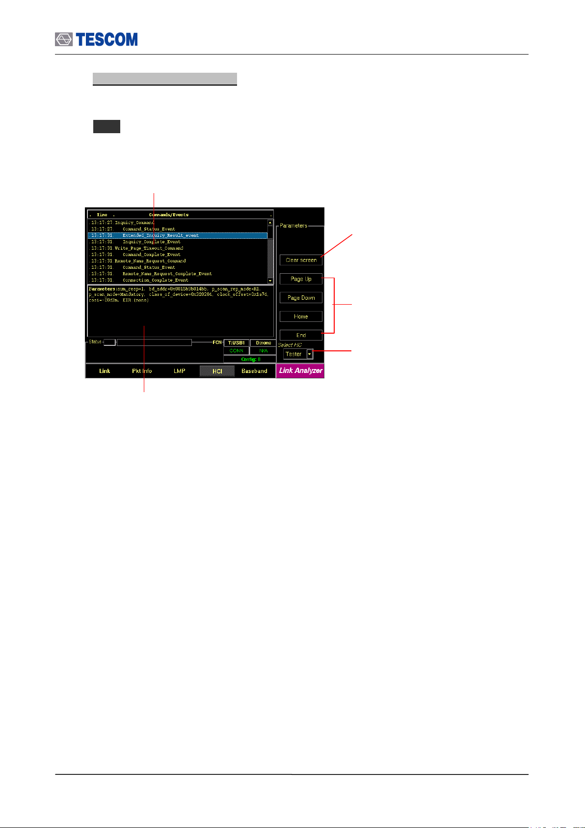
3. HCI commands and events: This screen shows the HCI commands and events sent
between the TC-3000C and the DUT, both from TC-3000C’s side and DUT’s side. To
access HCI screen, press
M4 soft key.
42
Page 43

3.3 Operation Procedure (Link Analyzer)
Start Record: When this menu is checked the
TC-3000C begins to record the Baseband
packets during the record time or until getting
as many packets as specified in the Num Pkts
menu. When the recording is finished this
menu is set to unchecked.
Clear Screen: Clear all packet information
Cursor movement functions: For
easy scrolling the messages
Baseband Packets: This window displays the
master clock, time offset from start of Rx slot in
hundreds nano-seconds, and the Baseband
Packets transmitted between the TC-3000C and
the DUT in hexadecimal.
Record time: The TC-3000C records
the Baseband packets during this time.
“0” mean unlimited time.
Number of packets: The TC-3000C
records the Baseband packets until
getting as many packets as specified in
the menu.
Packet Mask: This menu lets you select
the packet categories for triggering.
Access code / Header / Payload
First 9 bytes represent an Access code, next
3 bytes represent a Header after FEC (only
18 bytes are meaningful. Payload starts from
13th byte.
4. Baseband Packets: This screen shows the Baseband Packets transmitted between
the TC-3000C and the DUT in hexadecimal. To access Baseband screen, press M5
soft key.
43
Page 44
3.4 Operation Procedure (Host Analyzer)
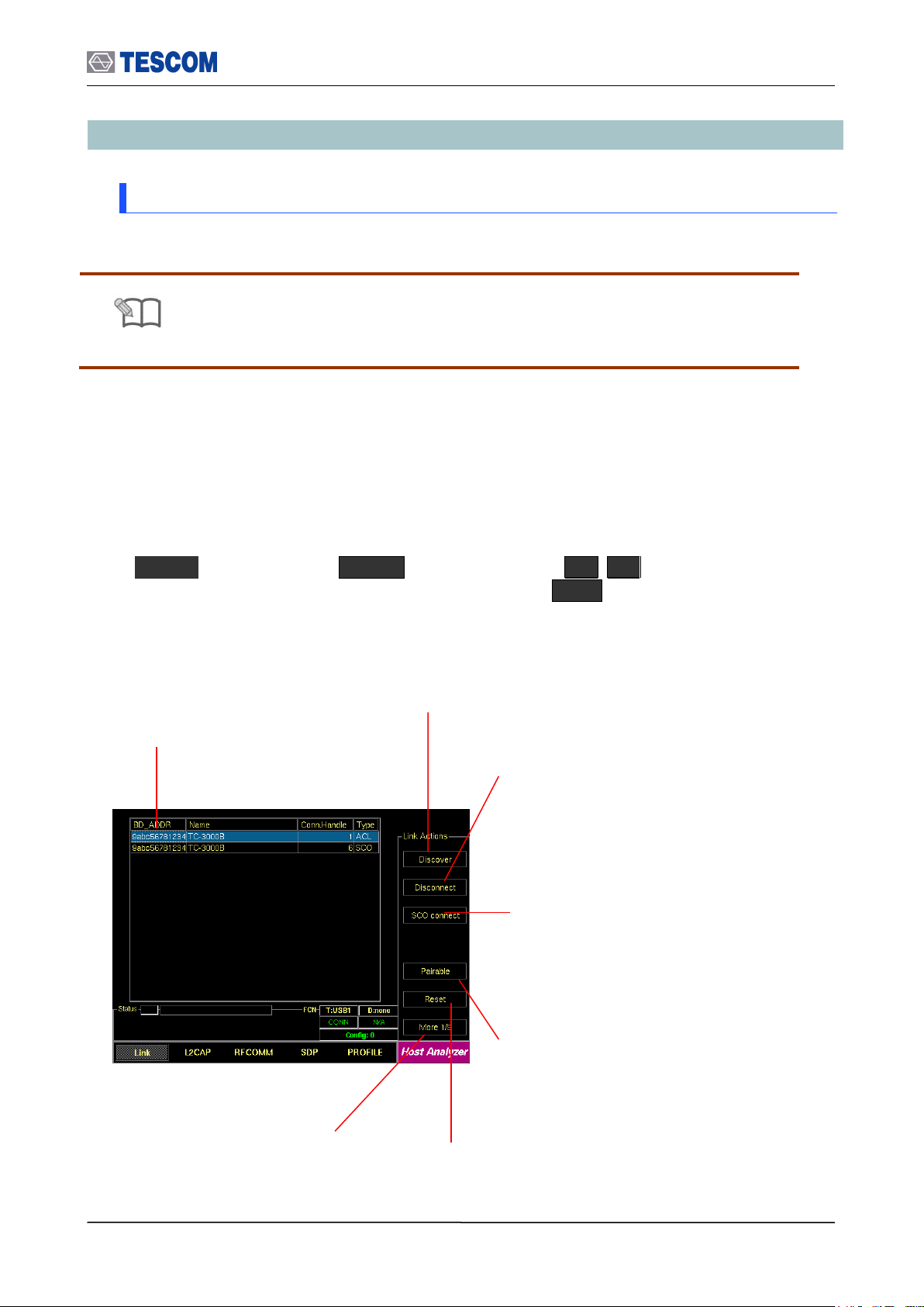
NOTE
“ 3.2 Basic Operation Procedure” should be performed before following steps
Show Devices Found: This
window display details about the
found devices.
Discover: Searches for all Bluetooth
devices that are in range and in
Inquiry Scan Mode through the Inquiry
procedure.
Connect/Disconnect: Creating connection to
highlighted DUT on the screen through the Page
procedure or disconnecting. This menu is
displayed when a DUT is discovered and listed on
the screen. If the highlighted DUT is connected,
this menu is changed to “Disconnect”.
SCO connect: Create SCO connection
to a highlighted DUT on the screen.
Pairable: Enables the TC-3000C to be
responder in scanning and pairing
procedure.
Reset: Resets the TC-3000C. In case
DUT is connected to the TC-3000C with
HCI, the DUT is reset simultaneously.
Change submenus: For setting
up Inquiry, Page, and test mode
parameters.
3.4 Operation Procedure (Host Analyzer)
3.4.1 Step 2. Creating Connection to DUT
Higher protocol data can be recorded in the Host Analyzer screen. In this screen, TC-3000C
also uses upper layer protocols; L2CAP, RFCOMM (AVDTP), SDP, and Profiles (AVRCP) to
make a connection to a DUT.
1. Selecting the Host Analyzer Screen: Host Analyzer screen can be accessed by pressing
the Menu hard key. Press Menu Rotary Knob or Select “Host
Analyzer” from the pop-up menu on the screen Press ENT .
44
Page 45
3.4 Operation Procedure (Host Analyzer)
Parameters
Range
Default
Descriptions
Inq. TO (1.28s)
1 ~ 48
48
Refer to Tester in Configuration
Page TO (slts)
1 ~ 65535
16000
Refer to Tester in Configuration
# responses
0 ~ 16
1
Refer to Tester in Configuration
HCI TO (ms)
1 ~ 65535
2000
Refer to Tester in Configuration
Parameters
Range
Default
Descriptions
Access Type
Discoverable
Connectable
Full Access
Full Access
Accessibility to Tester as a slave
T inqscan (slts)
18 ~ 4096
2048
Refer to Tester in Configuration
T winqscan (slts)
18 ~ 4096
18
Refer to Tester in Configuration
T pagescan (slts)
18 ~ 4096
2048
Refer to Tester in Configuration
T wpagescan (slts)
18 ~ 4096
18
Refer to Tester in Configuration
Scan TO (ms)
10000 ~
600000
Inquiry/Page Scan Timeout of Tester
NOTE
If you want to edit test configuration in detail, you can access to configuration
menus by pressing F8 in sequence. These menus operate globally;
changing the settings in this screen automatically changes that setting in all
screens where it is available. Refer to “3.9 Configuration.
2. Setting up # Inq. Response: You can set the Inquiry to end after the “# Inq.
Responses” (1 to 16). If there are several DUT that have to respond to Inquiry, set the
number of Inquiry response to more than 1. But if there is only one DUT, set the
number of Inquiry response to 1 for testing speed. TC-3000C will stop discovering
when receives this number of inquiry responses or the Inquiry Timeout is expired.
Press F8 one times for “More 2/5” menu Press F4
3. Setting up the profile type of DUT: You should define the profile type of DUT, before
beginning tests. To select the profile type, press F8 three times for “More 5/5”
menu in the Host Analyzer screen. press F2 and select the profile type of DUT.
4. Search for DUT: Press F8 for “More 1/5” menu press F2 key to search for
all Bluetooth devices that are in range and in Inquiry Scan Mode through the Inquiry
procedure. If the DUT is connected to the TC-3000C through the USB(HCI) port, the
TC-3000C read the Bluetooth device (BD) address and controls the DUT directly
through HCI. If you want to stop Inquiry process, press
F2 key again.
5. Select a DUT: Select a DUT that you want to test in the found devices by using
Rotary Knob or
keys.
6. Connect/Disconnect: Create connection to highlighted DUT on the screen through
the Page procedure by pressing F3 . When the highlighted DUT is connected, this
menu changes to “Disconnect”. To make a SCO connection, press F4 .
[ Inquiry Parameters ]
[ Scan Parameters ]
45
Page 46

[ Profile Parameters ]
Parameters
Range
Default
Descriptions
L2CAP TO (ms)
1 ~ 65535
2000
L2CAP Timeout
Defines the timeout of L2CAP commands execution
RFCOMM TO (ms)
1 ~ 65535
2000
RFCOMM Timeout
Defines the timeout of RFCOMM commands
execution
SDP TO (ms)
1 ~ 65535
2000
SDP Timeout
Defines the timeout of SDP commands execution
Profile TO (ms)
1 ~ 65535
2000
Profile Timeout
Defines the timeout of Profile commands execution
Type of Profiles
None
Headset
Handsfree
AudioGateway
Handsfree
Type of Profiles
Defines the profile type of DUT. If you select
“None”, only the lower layers of protocol are used to
make a connection with DUT in the same way as
Link Analyzer.
Gain control
Unchecked
If the DUT support the microphone and speaker
gain controls, checking this option enable TC3000C to control the volume of it.
Checking this menu causes “Speaker Volume” and
“Mic Volume” menu to be showed below.
Speaker Volume
0 ~ 15
15
Speaker Volume
Specifies the volume of DUT speaker in
consideration of the gain.
Mic Volume
0 ~ 15
15
Microphone Volume
Specifies the volume of DUT microphone in
consideration of the gain.
3.4 Operation Procedure (Host Analyzer)
46
Page 47
3.4 Operation Procedure (Host Analyzer)
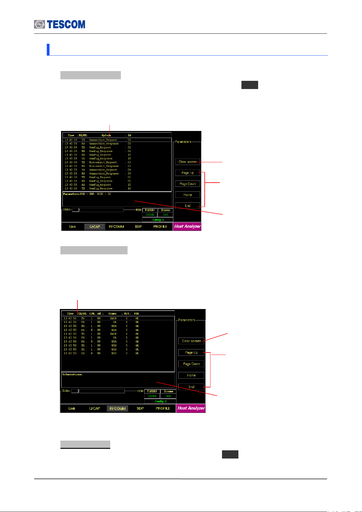
L2CAP Messages: This window displays the L2CAP
messages exchanged between the TC-3000C and the DUT.
RFCOMM Messages: This window displays the
RFCOMM messages exchanged between the
TC-3000C and the DUT.
Cursor movement functions: For
easy scrolling the messages.
Parameters window: This window
shows detail parameters about the
highlighted RFCOMM message.
Cursor movement functions: For
easy scrolling the messages.
Parameters window: This window
shows detail parameters about the
highlighted L2CAP message.
Clear screen: Clears all messages
Clear screen: Clears all messages
3.4.2 Step 3. Viewing the Recorded Data
1. L2CAP Messages: This screen shows the L2CAP messages exchanged between the
TC-3000C and the DUT. To access L2CAP screen, press M2 soft key.
2. RFCOMM messages: This screen shows the RFCOMM messages exchanged
between the TC-3000C and the DUT. To access RFCOMM screen, press M3 soft key.
3. SDP Messages: This screen shows the SDP messages exchanged between the TC3000C and the DUT. To access SDP screen, press M4 soft key.
47
Page 48

3.4 Operation Procedure (Host Analyzer)
Cursor movement functions: For
easy scrolling the messages
Parameters window: This window shows
detail parameters about the highlighted SDP
message.
Clear screen: Clears all messages
SDP Messages: This window displays the SDP
messages exchanged between the TC-3000C
and the DUT.
Cursor movement functions: For
easy scrolling the messages
Clear screen: Clears all messages
Profile Messages: This window displays
the Profile messages exchanged
between the TC-3000C and the DUT.
4. Profiles : This screen shows AT Commands transmitted between the TC-3000C and the DUT .
To access Profile screen, press M5 soft key.
48
Page 49
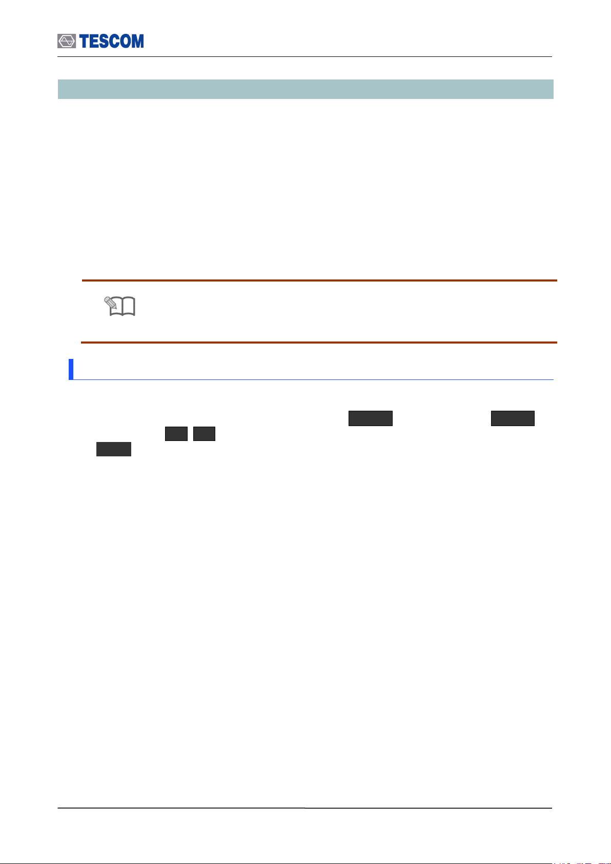
3.5 Operation Procedure (Measurement/Measurement2)
NOTE
3.2 “Basic Operation Procedure” should be performed before following steps.
3.5 Operation Procedure (Measurement/Measurement2)
This chapter describes the operation procedure of RF Measurement.
When you select the measurement screen or run the test cases, the TC-3000C makes a
connection to DUT that is discovered firstly and begins to test automatically although there
are several BT devices nearby. If you want to test a specific device in several devices, go
through the step 2 in the Link Analyzer screen or Host Analyzer screen in advance.
If there is a connection with DUT already, the TC-3000C begins the test immediately
without the connection procedure.
3.5.1 Step 3. Selecting the Measurement Screen
Measurement can be accessed by pressing the Menu hard key. Press Menu
Rotary Knob or Select “Measurement” from the pop-up menu on the screen
ENT
When you select the measurement screen, the TC-3000C makes a connection to DUT that
is discovered firstly and begins to measure RF signals automatically.
49
Page 50

3.5 Operation Procedure (Measurement/Measurement2)
Parameters
Range
Default
Channel
0 ~ 78, Hopping
Hopping
Span (MHz)
1, 1.25, 2, 2.5, 5, 10
10
Num of sweeps
1 ~ 50
1
Trace Mode
Average / Maxhold
Average
Ref. Level (dBm)
-80 ~ 40
-80 + Path Loss ~ 40 + Path Loss
dB/div
1 ~ 20
10
Center Frequency
Resolution Band Width
20dB Band Width
Start/Stop: When this menu is
pressed the tests will run once.
When the menu is pressed again
while the tests are running, the tests
will stop.
Channel: Selects the carrier frequency
channel, one of 79 channels or Hopping
mode. (Channel 0-78 : 2.402 – 2.480 GHz)
Span: Selects full screen frequency
span width.
Num of sweep: Specifies the number of times
that the analyzer sweeps the displayed
frequency span. This value directly affects
how long it takes to complete a measurement.
Trace Mode: Selects tracing mode, Average
or Maximum hold.
Line Markers: You can place line-shaped markers on the
screen to find the signal’s frequency and amplitude. To
activate a maker, press the Marker key in sequence.
An activated marker changes to a solid line. Turn the
knob to place the marker at the signal.
Readouts of markers amplitude and frequency: The
marker readouts have the same color as the marker
respectively. “d” displays a frequency difference between
yellow and red marker.
Ref. Level: Specifies the amplitude reference
level. The top line of the display is the
reference level. All signals displayed are
reference to this line.
dB/div: Sets the vertical amplitude per division
Test mode: Configures Bluetooth Test Mode
connection with the DUT
3.5.2 Step 4. Measuring RF Characteristics of DUT
1. Spectrum Analyzer: To access the spectrum analyzer screen, press M1 soft key.
This screen shows the spectrum of a channel in single channel or hopping mode.
50
Page 51
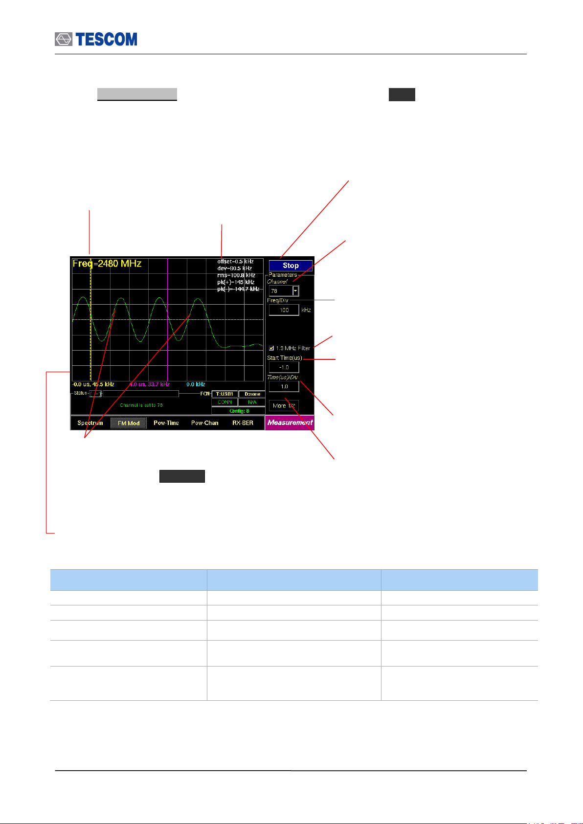
3.5 Operation Procedure (Measurement/Measurement2)
Parameters
Range
Default
Channel
0 ~ 78
Hopping
1 Ver Div. (kHz)
10 ~ 1000
100
1.3 MHz Filter
Checked
Start Time. (us)
-70~ 3124
Time(us)/div
0.1~ 60 @ 1 slot packet
0.1~ 180 @ 3 slots packet
0.1 ~ 300 @ 5 slots packet
Center Frequency:
Displays channel
frequency.
Channel: Select the carrier frequency
channel, one of 79 channels or Hopping
mode. (Channel 0-78: 2.402 – 2.480 GHz)
1.3 MHz Filter: Enables 1.3 MHz Low Pass
Line Markers: You can place line-shaped markers on the
screen to find the signal’s frequency and time. To activate
a maker, press the Marker key in sequence. An
activated marker changes to a solid line. Turn the knob to
place the marker at the signal.
Readouts of markers time and frequency: The marker
readouts have the same color as the marker respectively.
Test mode: Configures Bluetooth Test Mode
connection with DUT
Time (us)/div: Sets the horizontal time per
division
Start Time: Specifies the start point to display the
measured signals. “0” means the start point of a
slot time (625 uS).
All following values are measured between yellow and blue marker.
offset: Carrier Frequency offset
dev: Average of absolute deviation values
rms: RMS value of deviation
pk(+): Positive maximum deviation
pk(-): Negative maximum deviation
Start/Stop: When this menu is pressed the
tests will run once. When pressed again
while the tests are running, the testing will
stop.
Freq/Div: frequency value of one vertical grid
on screen
2. FM Modulation: To access FM Modulation screen, press M2 soft key. This screen
shows the modulation characteristics of a channel in single channel or hopping mode.
51
Page 52

3.5 Operation Procedure (Measurement/Measurement2)
Parameters
Range
Default
Channel
0 ~ 78, Hopping
Hopping
Ref. Level (dBm)
-80 ~ 40
-80 + Path Loss ~ 40 + Path Loss
dB/div
1 ~ 20
10
1.3 MHz Filter
Checked
Start Time (us)
-70 ~ 3124
Time(us)/div
0.1 ~ 60 @ 1 slot packet
0.1 ~ 180 @ 3 slots packet
0.1 ~ 300 @ 5 slots pakcet
Channel Frequency
Average Power
Peak
Start/Stop: When this menu is
pressed the tests will run once.
When the menu is pressed again
while the tests are running, the tests
will stop.
Channel: Selects the channel, one of 79
channels or Hopping mode. (Channel 0-78 :
2.402 – 2.480GHz)
1.3 MHz Filter: Enables 1.3 MHz Low
Pass Filter
Line Markers: You can place line-shaped markers on the
screen to find the signal’s amplitude and time. To activate
a maker, press the Marker key in sequence. An
activated marker changes to a solid line. Turn the knob to
place the marker at the signal.
Readouts of cursors time and frequency: The marker
readouts have the same color as the marker respectively.
dB/Div: Sets the vertical amplitude per
division
Test mode: Configures Bluetooth test
Mode connection with DUT
Time(us)/div: Sets the horizontal time
per division
Start Time: Specifies the start point to
display the measured signals. “0” means
the start point of a slot time (625 us).
Ref. Level: Specifies the amplitude reference
level. The top line of the display is the
reference level. All signals displayed are
reference to this line.
3. Power versus Time: To access Pow-Time screen, press M3 soft key. This screen
shows the channel power measure of a channel in single channel or hopping mode.
52
Page 53
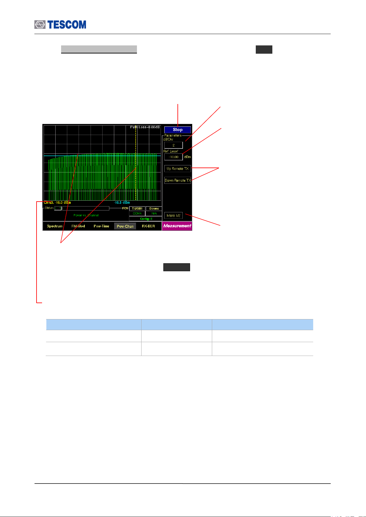
3.5 Operation Procedure (Measurement/Measurement2)
Parameters
Range
Default
dB/div
0 ~ 20
10
Ref. Level (dBm)
-80 ~ 40
-80 + Path Loss ~ 40 + Path Loss
Start/Stop: When this menu is pressed the tests will
run once. When the menu is pressed again while the
tests are running, the tests will stop.
Up/Down Remote Tx: Increasing/Decreasing
the DUT TX power. This function is available
only when the DUT supports the power control
option. The step size depends on the DUT
specification (2~ 8 dB).
Line Markers: You can place line-shaped markers on the
screen to find the channel’s amplitude and set reference
amplitude. To activate a maker, press the Marker key
in sequence. An activated marker changes to a solid line.
Turn the knob to place the marker at the signal.
Readouts of markers channel and amplitude: The marker
readouts have the same color as the marker respectively.
dB/Div: Sets the vertical amplitude per
division
Test mode: Configures Bluetooth Test
Mode connection with DUT
Ref. Level: Specifies the amplitude reference
level. The top line of the display is the
reference level. All signals displayed are
reference to this line.
4. Power versus Channel: To access Pow-Chan screen, press M4 soft key. This
screen shows the channel power measures of every channels, 0~78.
53
Page 54
3.5 Operation Procedure (Measurement/Measurement2)
Parameters
Range
Default
DUT RX level (dBm)
-80 ~ 0
0
Bites to Test
0 ~ 500000
10000
Dirty TX
Unchecked
BER: Displays the BER measure to the
sent bytes that are specified in “Length”
menu.
Start/Stop: When this menu is pressed the tests
will run once. When pressed again while the
tests are running, the testing will stop.
DUT RX level: Sets expected value of DUT Rx
Power.
Dirty TX: Enables “Dirty Transmission
mode” TC-3000C transmits the dirty
transmitter signal in accordance to the
Bluetooth Test Specification.
Line Markers: You can place line-shaped marker on
the screen to set reference BER. Turn the knob to
place the marker at the screen.
Readouts of marker BER and bit stream information:
The cursor BER, the total sent bytes, the Error bits, and
the cumulated BER are displayed. The cumBER
(cumulated BER) displays BER measure to total sent
bytes.
Test mode: Configures Bluetooth Test
Mode connection with DUT
Bytes to Test: Specifies the length of
data to measure.
The top line of the display is the reference
level 100%. The vertical percent per division
go down by one tenth.
5. BER (Bit Error Rate): To access BER screen, press M5 soft key. The DUT
sensitivity is determined by using a Bit Error Rate (BER). This screen shows the BER
measurements that are carried out by comparing data in the payload fields transmitted
by the TC-3000C with data in the payload fields received from the DUT. This test is
performed in Loopback test mode without regard to the preset test mode.
54
Page 55

3.5 Operation Procedure (Measurement/Measurement2)
Parameters
Range
Default
Start Level(dBm)
-80 ~ 0
-45
Stop Level(dBm)
-80 ~ 0
-50
Step Level(dBm)
0.01 ~ 80
0.10
BER Spec(%)
0 ~ 100
0.10
Bytes to Test
1 ~ 500000
10000
Display currently executing
RF level and BER
Start Level: Set start power for BER Level
Search
Dirty TX: Enables “Dirty Transmission
mode” TC-3000C transmits the dirty
transmitter signal in accordance to the
Bluetooth Test Specification.
Line marker, Level and BER: When the start key is
pressed to run BER search function, the TC3000C will fine
sensitivity level and the Line marker will be placed that
sensitivity level position. Press the marker key to make it
active and display BER value of marker line.
Step Level: Set step Power of BER Search
Stop Level: Set last power for BER Level
Search
BER Spec: Set BER Spec.
Bytes to Test: Specifies the length of data
to measure
Line marker and BER Spec(%) value: When the start key
is pressed, it will display target BER spec value. If the
marker is activated, it will display the BER value of marker
line.
The most top line means 100% and next
lines mean 1/10 of above line (Log scale)
Start/Stop: When this menu is pressed the
tests will run once. When the menu is
pressed again while the tests are running,
the tests will stop.
6. BER Search : This function will automatically find the sensitivity level for BER Spec (ex
0.1%). To execute BER Level Search function, the DUT must support loopback test mode.
55
Page 56
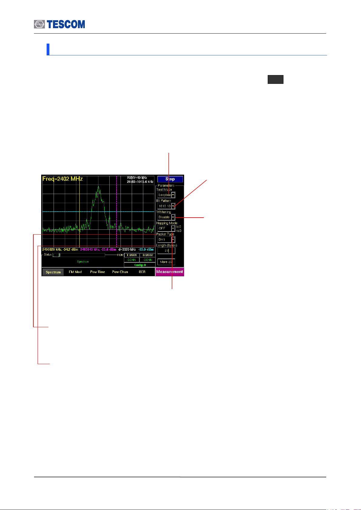
3.5 Operation Procedure (Measurement/Measurement2)
Bit Pattern: Select the bit pattern being
transmitted. Supported patterns are 0000
0000, 11111111, 10101010, 11110000, and
PRBS9.
Whitening: Enable or disable whitening. In
transmitter test mode, the packets exchanged
between TC-3000C and DUT are not scrambled
with the whitening sequence. This parameter is
ignored in transmitter test mode.
Hopping Mode: Choose to make measurement on a specific channel or in Bluetooth frequency hopping
mode. The “Off” require specifying Tx and Rx channel.
Packet Type: Select a Bluetooth specific single or multi slot packet. The following packet types are
available: DM1, DH1, HV1, HV2, HV3, AUX1, DM3, DH3, DM5, DH5, EV3, EV4, EV5, 2-DH1, 3-DH1, 2DH3, 3-DH3, 2-DH5, 3-DH5, 2-EV3, 3-EV3, 2-EV5, 3-EV5. For the transmitter test mode, only packets
without FEC should be used; i.e. HV3, DH1, DH3, DH5 and AUX1 packets.
Length: the length of packets can be adjusted from 1 to 27 for 1slot packets, 1 to 183 for 3 slot
packets and 1 to 339 for 5 slot packets.
Test Mode: You can choose Loopback or Transmitter or Null Packet. Null Packet mode is used to test DUTs
that have no test mode support. In this mode, the TC-3000C uses the packets without payloads and
measurements are not performed in accordance with the Bluetooth Test specification and some test cases
can’t be carried out. A NULL packet has no payload but can be used for power, initial frequency, and
spectrum without having to activate test mode.
3.5.3 Step 5. Setting Up Test Mode and Parameters
The Test Parameters let you configure Test mode, Bit pattern, Whitening, Hopping mode,
Packet Type, and Packet length. This menus can be accessed by pressing F8 in every
measurement screen.
56
Page 57
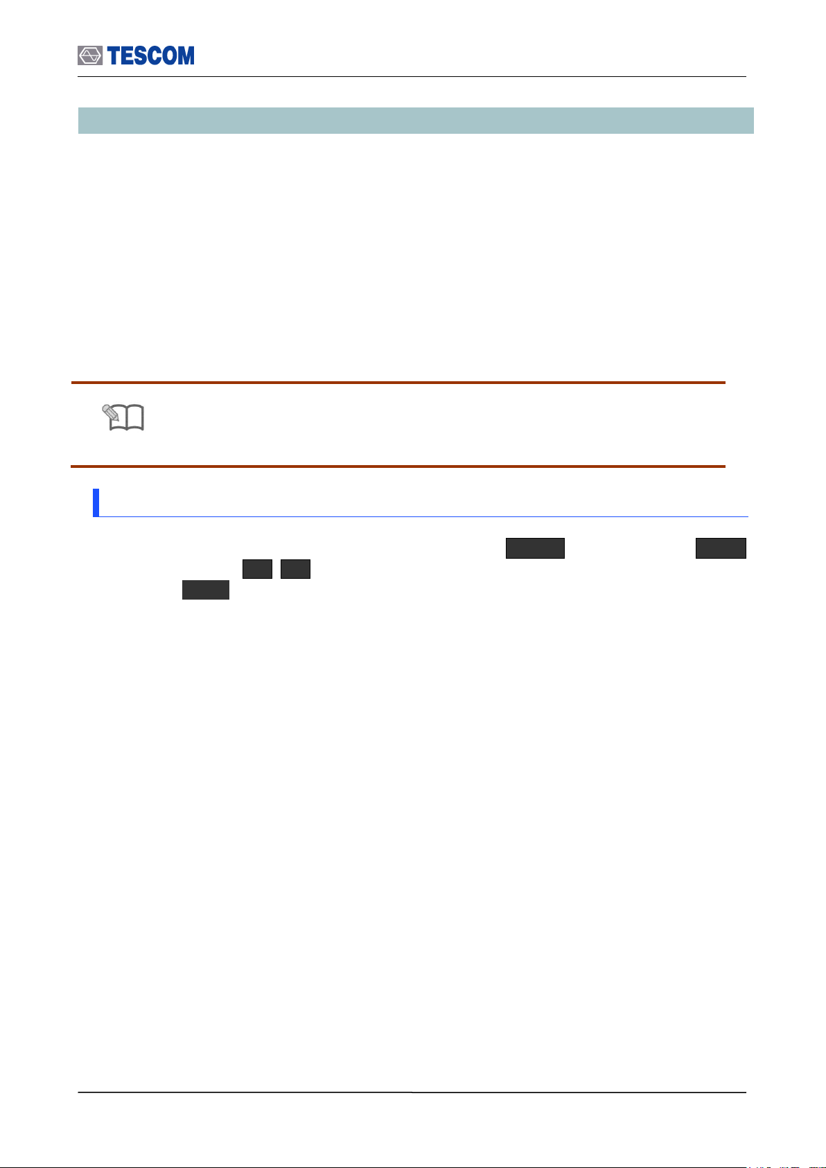
3.6 Operation Procedure (EDR Measurement)
NOTE
“Basic Operation Procedure” on page 3-12 should be performed before following
steps.
3.6 Operation Procedure (EDR Measurement)
This chapter describes the operation procedure of EDR Measurement.
When you select the EDR measurement screen or run the test cases, the TC-3000C
makes a connection to DUT that is discovered firstly and begins to test automatically
although there are several BT devices nearby. If you want to test a specific device in
several devices, go through the step 2 in the Link Analyzer screen or Host Analyzer screen
in advance.
If there is a connection with DUT already, the TC-3000C begins the test immediately
without preceding connection procedure.
3.6.1 Step 3. Selecting the EDR Measurement Screen
EDR Measurement can be accessed by pressing the Menu hard key. Press Menu
Rotary Knob or Select “EDR Measurement” from the pop-up menu on the
screen ENT
When you select the measurement screen, the TC-3000C makes a connection to DUT that
is discovered firstly and begins to measure RF signals automatically.
57
Page 58

3.6 Operation Procedure (EDR Measurement)
Parameters
Range
Default
Max of X-axis
1~ 50000
5000
Max. Of X-axis
1 ~ 50000
5000
Num of symbol
1 ~ 200
100
Pointer
Small, Mid, Large
Mid
Symbol start
0
Num of symbol : Number of PSK symbols
displayed on screen, To see more symbol,
increase this value
Pointer : Graphical size of symbol
Symbol start : Specifies the start point to
display PSK symbol. “0” means the start point of
PSK Payload
Transmitted PSK symbol
from DUT
RMS DEVM: Variance of DEVM(Differential
Error Vector Magnitude)
Peak DEVM: maximum DEVM
Freq. Offset: carrier frequency offset of PSK
Test mode: Configures Bluetooth Test
Mode connection with DUT
Start/Stop: When this menu is pressed the tests
will run once. When pressed again while the
tests are running, the testing will stop.
3.6.2 Step 4. Measuring EDR Characteristics of DUT
1. Constellation : To access the constellation, press M1 soft key. This screen shows
the I-Q constellation spectrum of a channel in single channel or hopping mode.
58
Page 59

3.6 Operation Procedure (EDR Measurement)
Num. Of packet: specifies the number of packet
to measure
BER: Displays the TX-BER measure to
the sent bytes that are specified in
“Length” menu.
PER: Displays the TX-PER(Packet
Error Rate) measure
Test mode: Configures Bluetooth Test
Mode connection with DUT
2. TX-BER (Bit Error Rate): To access TX-BER screen, press M2 soft key. The
purpose of this measurement is to test DUT’s PSK modulation quality. This test is not the
DUT’s RX sensitivity so output power of TC-3000C should be set enough high. This
screen shows the TX-BER measurements that are carried out by checking data in PSK
payload fields received from the DUT. This test is performed in Transmitter test mode
only.
59
Page 60
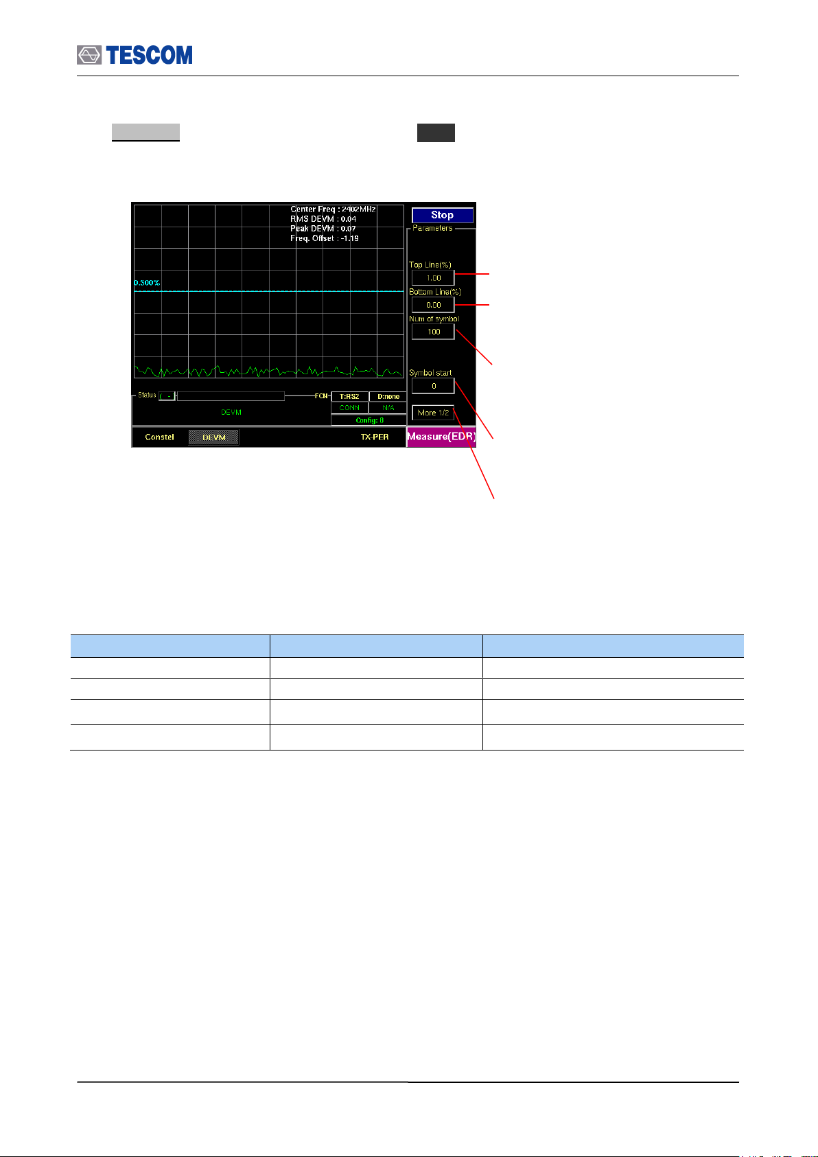
3.6 Operation Procedure (EDR Measurement)
Parameters
Range
Default
Top Line
0.9 ~ 100
1.00
Bottom Line
0 ~ 0.1
0.00
Num of symbol
1 ~ 200
100
Symbol start
0 ~ 145
0
Num of symbol : Number of PSK symbols
displayed on screen, To see more symbol,
increase this value
Symbol start : Specifies the start point to
display PSK symbol. “0” means the start point of
PSK Payload
Test mode: Configures Bluetooth Test Mode
connection with the DUT
Top Line : Specifies the amplitude of top line
Bottom Line : Specifies the amplitude of
Bottom line
3. DEVM : To access DEVM screen, press M3 soft key. This screen shows the DEVM
according to PSK payload position. X-axis means position of PSK payload.
60
Page 61
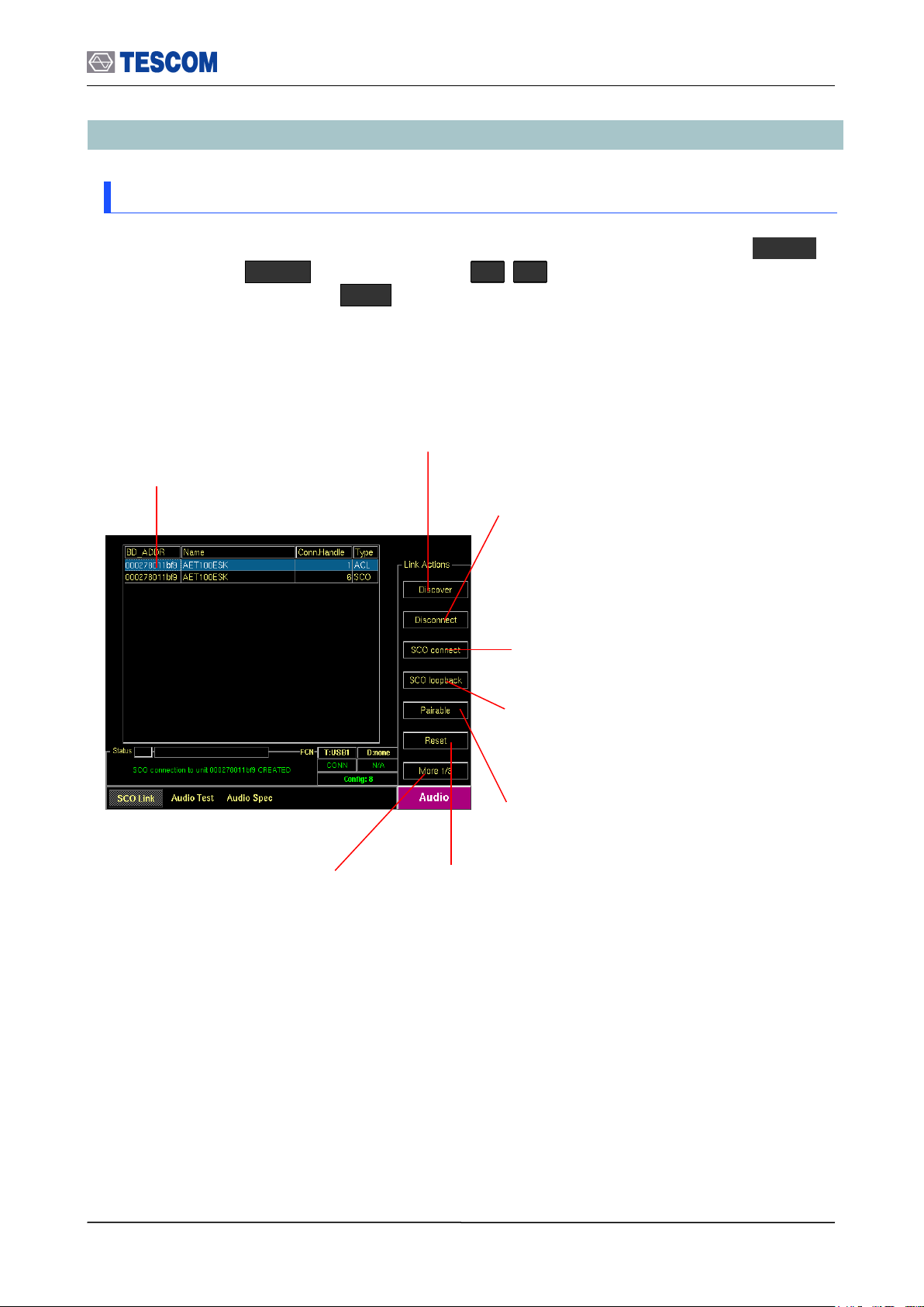
3.7 Operation Procedure (Audio Analyzer)
Show Devices Found: This
window display details about the
found devices.
Discover: Searches for all Bluetooth
devices that are in range and in
Inquiry Scan Mode through the Inquiry
procedure.
Connect/Disconnect: Creating connection to
highlighted DUT on the screen through the Page
procedure or disconnecting. This menu is
displayed when a DUT is discovered and listed on
the screen. If the highlighted DUT is connected,
this menu is changed to “Disconnect”.
SCO connect: Create SCO connection
to a highlighted DUT on the screen.
Pairable: Enables the TC-3000C to be
responder in pairing procedure.
Change submenus: For setting
up Inquiry, Page, and test mode
parameters.
SCO loopback: Enables the SCO
loopback test.
Reset: Resets the TC-3000C. In case
DUT is connected to the TC-3000C with
HCI, the DUT is reset simultaneously.
3.7 Operation Procedure (Audio Analyzer)
3.7.1 Step 2. Creating Connection to DUT
1. Selecting the Audio Screen: Audio screen can be accessed by pressing the Menu
hard key. Press Menu Rotary Knob or Select “Audio” from the pop-up
menu on the screen Press ENT .
61
Page 62

3.7 Operation Procedure (Audio Analyzer)
Parameters
Range
Default
Descriptions
Packet Type
HV1, HV2, HV3
HV3
Defines the packet type of SCO Link
Air Coding
CVSD, u-law, A-law
CVSD
Defines voice coding type
Delay (s)
0, 2, 5
2
Defines the delay time that TC-3000C
loopback the SCO Data received from
DUT.
NOTE
Selecting Audio Gate as the profile type causes “Talk” menu to be showed
and "Discover” menu to disappear. In case of Audio Gate (HS-AG or HF-AG),
TC-3000C discovers DUT and creates ACL / SCO connection at in a time by
pressing F2 (Talk).
3-2-2 Step 2. Selecting DUT and Creating Connection to DUT
2. Setting up the profile type of DUT: You should define the profile type of DUT, before
beginning tests. To select the profile type, press F8 two times for “More 3/3” menu
in the Audio screen. press F2 and select the profile type of DUT.
3. Setting up the parameters for DUT: Specify the parameters related to Signal Source.
Press F8 for “More 2/3 or 3/3” menu press F2 ~ F4 key.
4. Search for DUT: Press F8 for “More 1/3” menu press F2 key to search for
all Bluetooth devices that are in range and in Inquiry Scan Mode through the Inquiry
procedure. If the DUT is connected to the TC-3000C through the HCI port, the TC3000C read the Bluetooth device (BD) address and controls the DUT directly through
HCI. If you want to stop Inquiry process, press
F2 key again.
5. Select a DUT: Select a DUT that you want to test in the found devices by using
Rotary Knob or
keys.
6. Connect/Disconnect: Create connection to highlighted DUT on the screen through
the Page procedure by pressing F3 . When the highlighted DUT is connected, this
menu changes to “Disconnect”. To make a SCO connection, press F4 .
[ Voice Parameters ]
62
Page 63

[ Profile Parameters ]
Parameters
Range
Default
Descriptions
Type of Profile
None
Headset
Hands free
HS-AG
HF-AG
Audio-SNK
Audio-SRC
Hands free
Type of Profiles
Defines the profile type of DUT
Send Ring
Unchecked
When it is “checked” TC-3000C transmits
RING with AT command.
Gain control
Unchecked
If the DUT support the microphone and
speaker gain controls, checking this option
enable TC-3000C to control the volume of
it. Checking this menu causes “Speaker
Volume” and “Mic Volume” menu to be
showed below.
Speaker Volume
0 ~ 15
15
Speaker Volume
Specifies the volume of DUT speaker.
Mic Volume
0 ~ 15
15
Microphone Volume
Specifies the volume of DUT microphone .
Transfer Type
Built-in
User File
Built-in
Select to transmit the internal audio tone
or the external source which user saved.
Copy Source
Copy an audio source file from USB
Memory to TC-3000C. The name of file
must be “tc3000.sbc” and only a file can
be saved.
Sample Frequency
16000
32000
44100
48000
32000
The sample frequency of the audio source
(SBC)
Subbands
4, 8 8 The Subband of the audio source (SBC)
Bitpool
2 ~ 250
32
The Bitpool of the audio source (SBC)
3.7 Operation Procedure (Audio Analyzer)
3.7.2 Step 3. Verification of Speech Loopback for Mono Headset
Pressing F5 enable TC-3000C to SCO loopback mode. In this test, TC-3000C loopback
all SCO Data received from DUT. You can listen to your voice from Headset speaker
after the delay time specified and verify the performance (howling, echo, noise) of
microphone and speaker simply.
To stop the SCO loopback, press F5 again.
63
Page 64
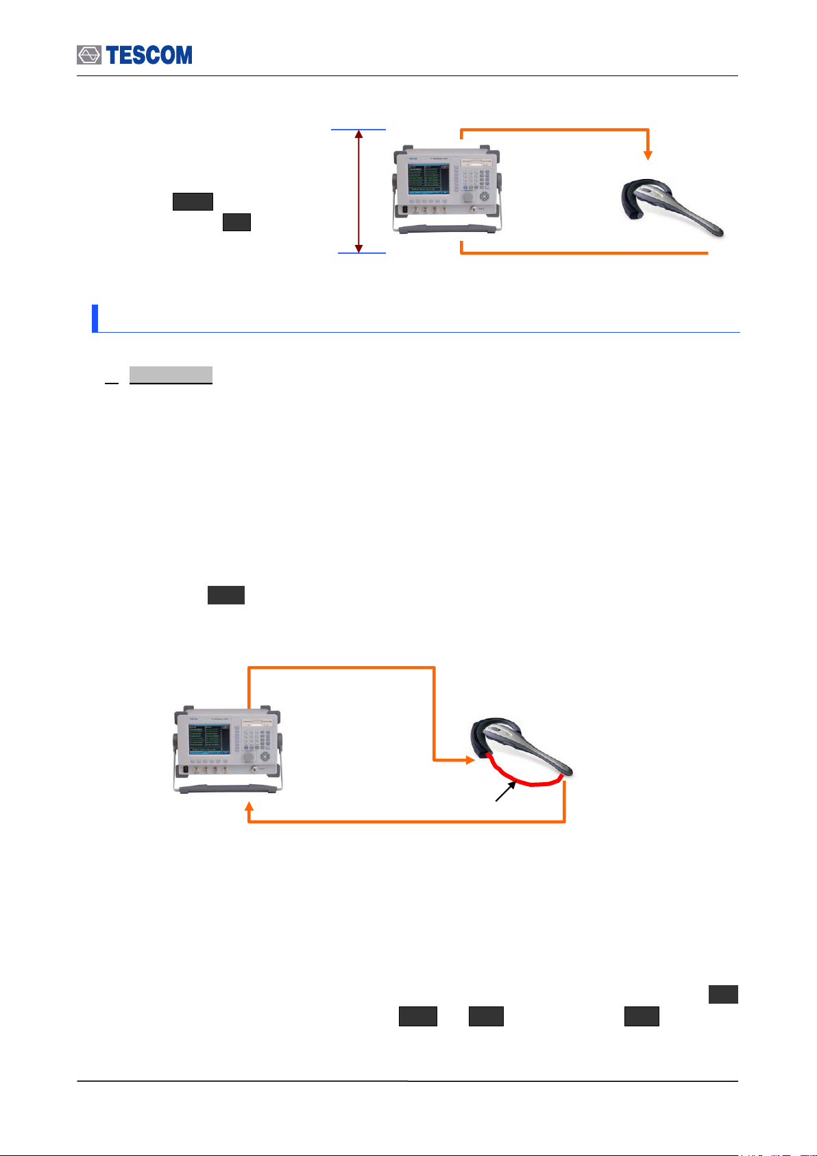
3.7 Operation Procedure (Audio Analyzer)
Micro Phone
Speaker
Audio Path
Time Delay: You can specify
this value in the Delay (s) menu.
Press F8 for “More 2/3”
menu Press F4 .
Send the 1 kHz or 400Hz tone
received from the Sound Tube to TC3000C.
Send 1 kHz or 400 Hz tone to DUT Speaker
Audio Path
Sound Tube
3.7.3 Step 4. Measuring Audio Characteristics of DUT
1. Audio Test: The following parameters are displayed in the Audio Test screen during
the test: Audio Frequency, Fundamental Power, RMS, SINAD, ICF (Initial Carrier
Frequency Tolerance) and Distortion.
[Typical Mono Headset test configuration]
TC-3000C sends an internally generated 1 kHz or 400 Hz tone to Headset speaker as a
diagram below. The tone signal is transmitted from the speaker to the microphone through
a sound tube. (In case of mobile phone, it is transmitted via internal audio path between
the speaker and the microphone). The TC-3000C receives the tone signal from DUT and
the audio spectrum and distortion of the signal are computed. To access the Audio Test
screen, press M2 soft key.
[Typical Stereo Headset test configuration]
TC-3000C sends an internally generated 1 kHz and 400 Hz tone to left and right of
Headset speaker as a diagram below. The tone signal is transmitted from the speaker to
the Base Band IN 1 or 2 port of TC-3000C through the audio cable connected to the
microphone. The TC-3000C receives the tone signal from DUT and the audio spectrum
and distortion of the signal are computed. To access the Audio Test screen, press M2
soft key. Before starting the test, .press M2 F8 “More 2/2” F4 and make
sure if “Audio Inport” is set correctly.
64
Page 65
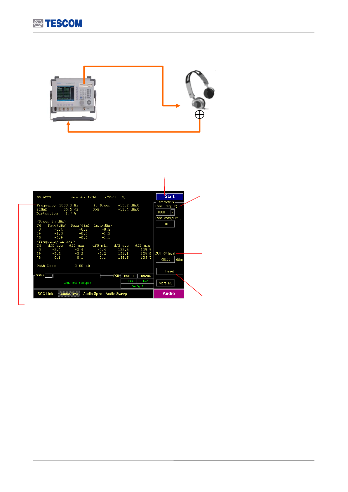
3.7 Operation Procedure (Audio Analyzer)
Start/Stop: When this menu is pressed the tests
will run once. When the menu is pressed again
while the tests are running, the tests will stop.
Tone Freq (Hz): Defines the tone frequency
for the test.
Measurement Window:
BD_ADDR: Bluetooth Address of DUT
Name: The friendly name of DUT
Frequency: The frequency of fundamental waveform
F. Power: The magnitude of fundamental waveform
RMS: the RMS magnitude of the signal
SINAD: This is a way that expresses total harmonic distortion plus noise. It is the RMS magnitude of the
signal divided by the RMS magnitude of the difference between the signal and the fundamental. This
measurement is expressed only in dB.
Distortion: Total harmonic distortion (THD) plus noise.
Reset: Clears all values
Tone level (dBm0): Specifies the power
of the TX audio signal.
DUT RX level: Specifies the DUT RX level.
TC-3000C controls the TX level for DUT to
receive the level specified in consideration of
the Path Loss.
Send the audio tone from the speaker to
BB IN 1 or 2 by using a microphone.
. Send 1 kHz (Left) and 400 Hz (Right) tone to DUT Speaker
Audio Path
Microphone
BB IN 1 or 2
RF Port
65
Page 66

3.7 Operation Procedure (Audio Analyzer)
Parameters
Range
Default
Tone Freq (Hz)
1000, 400
1000
Tone level (dBm0)
-70 ~ 3
-10
CH1 Freq(Hz)
20~20000
1000
CH2 Freq(Hz)
20~20000
400
CH1 level(dBm0)
-70~3
-3
CH2 level(dBm0)
-70~3
-3
DUT RX level
-80 ~ 0
-30.00
Channel(3)
0-39-78
Meas.Mode
Continuous, Single
Continuous
Audio In (Hz)
1000, 400
1000
Audio Inport
Port1(BB IN1), Port2(BB IN2)
Port1(BB IN1)
Num of Avg
1 ~ 100
1
Lower Freq(Hz)
20~4000
200
Upper Freq(Hz)
20~4000
3500
66
Page 67

3.7 Operation Procedure (Audio Analyzer)
Parameters
Range
Default
Tone Freq (Hz)
1000, 400
1000
Tone level (dBm0)
-70 ~ 3
-10
dBm0/div
1 ~ 20
10
Ref. Level (dBm0)
-80 ~ 40
0
Num of Avg
1 ~ 100
1
DUT RX level
-80 ~ 0
-30.00
Line Markers: You can place line-shaped markers on the
screen to find the signal’s frequency and time. To activate
a maker, press the Marker key in sequence. An
activated marker changes to a solid line. Turn the knob to
place the marker at the signal.
Readouts of markers Frequency and Level: The
marker readouts have the same color as the marker
respectively.
Start/Stop: When this menu is pressed the tests will run
once. When pressed again while the tests are running, the
testing will stop.
Ref. Level: Specifies the amplitude reference
level. The top line of the display is the
reference level. All signals displayed are
reference to this line.
dBm0/div: Sets the vertical amplitude per
division.
Tone level (dBm0): Specifies the power
of the TX audio signal.
DUT RX level: Specifies the DUT RX level.
TC-3000C controls the TX level in
consideration of the Path Loss so that the
DUT can receive the level specified
Tone Freq (Hz): Defines the tone frequency
for the test.
Number of Average: Measurement Averaging.
The signal averaging improves the signal to noise
ratio. The noise, i.e., the measurement error,
decreases by 1/SQRT(N) for N averages, but the
measurement time increases by N times.
Increasing averaging will reduce the measurement
fluctuation.
2. Audio Spectrum: TC-3000C has the ability to analyze the frequency spectrum of an
audio signal. You can measure frequency, amplitude, and harmonics of the audio signal in
this screen. The frequency range of spectrum is from 0 Hz to 4 kHz (sampling frequency =
8 kHz). To access Audio spectrum screen, press M3 soft key.
67
Page 68

3.7 Operation Procedure (Audio Analyzer)
Parameters
Range
Default
Start Freq (Hz)
30 ~ 3900
300
Stop Freq (Hz)
30 ~ 3900
3300
Step Freq (Hz)
15 ~ 3870
100
Tone level (dBm0)
-70 ~ 3
-10
Ref. Level (dBm0)
-80 ~ 40
0
dB/Div
0.1 ~ 20
10
Num of Avg
1 ~ 100
1
Meas Delay (ms)
30 ~ 1000
100
Line Markers: You can place line-shaped markers on the
screen to find the signal’s frequency and time. To activate
a maker, press the Marker key in sequence. An
activated marker changes to a solid line. Turn the knob to
place the marker at the signal.
Readouts of markers RMS, Distortion, and
frequency: The marker readouts have the same
color as the marker respectively.
Start/Stop: When this menu is pressed the tests will run
once. When pressed again while the tests are running,
the testing will stop.
Ref. Level: Specifies the amplitude reference
level. The top line of the display is the
reference level. All signals displayed are
reference to this line.
Step Freq (Hz): Specifies the frequency step
to sweep.
Start Freq (Hz): Specifies the start
frequency to sweep.
Stop Freq (Hz): Specifies the stop
frequency to sweep.
dB/Div: Sets the vertical amplitude per
division
Number of Average: Measurement Averaging.
The signal averaging improves the signal to noise
ratio. The noise, i.e., the measurement error,
decreases by 1/SQRT(N) for N averages, but the
measurement time increases by N times.
Increasing averaging will reduce the measurement
fluctuation.
Measurement Delay: Specifies the source
delay time (the time between setting the source
and taking the measurement) in milliseconds.
Tone level (dBm0): Specifies the power of
the TX audio signal.
3. Audio Sweep: TC-3000C’s internal audio tone source can be set to sweep up to 3900
Hz (minimum 100 Hz step) and then return the distortion and RMS volts for each
frequency. Sweep results are displayed on the screen To access Audio spectrum screen,
press M4 soft key.
68
Page 69

3.8 Operation Procedure (Bluetooth Conformance Test)
Category
TC identifier
Description
Test Mode
RF
(Transmitter)
TRM/CA/01/C
Output power
TX, Loopback, Null packet
TRM/CA/02/C
Power Density
TX, Loopback, Null packet
TRM/CA/03/C
Power Control
TX, Loopback, Null packet
TRM/CA/04/C
TX Output Spectrum – Frequency range
TX, Loopback, Null packet
TRM/CA/05/C
TX Output Spectrum – 20dB Bandwidth
TX, Loopback, Null packet
TRM/CA/06/C
TX Output Spectrum – Adjacent channel power
TX, Loopback
TRM/CA/07/C
Modulation Characteristics
TX, Loopback
TRM/CA/08/C
Initial Carrier Frequency Tolerance
TX, Loopback, Null packet
TRM/CA/09/C
Carrier Frequency Drift
TX, Loopback
RF
(Receiver)
RCV/CA/01/C
Sensitivity – Single slot packets
Loopback
RCV/CA/02/C
Sensitivity – Multi-slot packets
Loopback
RCV/CA/06/C
Maximum Input Level
Loopback
BER + FER
Quick (OP+MOD+ICFT+CFD)
BT LE
TRM-LE/CA/01/C
Output power
TRM-LE/CA/03/C
In-Band Emissions
TRM-LE/CA/05/C
Modulation Characteristics
TRM-LE/CA/06/C
Carrier Frequency Offset and Drift
RCV-LE/CA/01/C
Receiver Sensitivity
RCV-LE/CA/06/C
Maximum Input Signal Level
RCV-LE/CA/07/C
PER Report integrity
Quick (OP+MOD+CFOD)
EDR
(Enhanced
Data Rate)
TRM/CA/10/C
EDR Relative Transmit Power
TX, Loopback
TRM/CA/11/C
EDR Carrier Frequency Stability & Modulation
Accuracy
TX, Loopback
TRM/CA/12/C
EDR Differential Phase Encoding
TX
TRM/CA/13/C
EDR In-band Spurious Emissions
TX, Loopback
3.8 Operation Procedure (Bluetooth Conformance Test)
This chapter describes the operation procedure of Bluetooth Conformance Test. You can test
BT device with only a single keystroke. When the Start key is pressed, the TC-3000C
instates a link, activates Test Mode, performs the measurements and reports the results with
batch processing. Under the Test Mode (Transmitter or Loop back), tests are made exactly
as defined in the Bluetooth Test Specification. The tables below represent the supported test
cases.
69
Page 70

3.8 Operation Procedure (Bluetooth Conformance Test)
RCV/CA/07/C
EDR Sensitivity
Loopback
RCV/CA/08/C
EDR BER Floor Performance
Loopback
RCV/CA/09//C
EDR Maximum Input Level
Loopback
NOTE
“Basic Operation Procedure” on page 3-12 should be performed before following
steps.
Combined Test Case: Output
Power, Modulation Characteristics,
Initial Carrier Frequency Tolerance,
and Carrier Frequency Drift are
combined in this menu.
Combined Test Case for “Quick Test”
To reduce test time, TC-3000C combine several test cases into one menu. In this Test Case,
all default values of parameters are optimized in consideration of the test time. You can
perform four Test Cases (Output Power, Modulation Characteristics, Initial Carrier Frequency
Tolerance, and Carrier Frequency Drift) at once.
70
Page 71
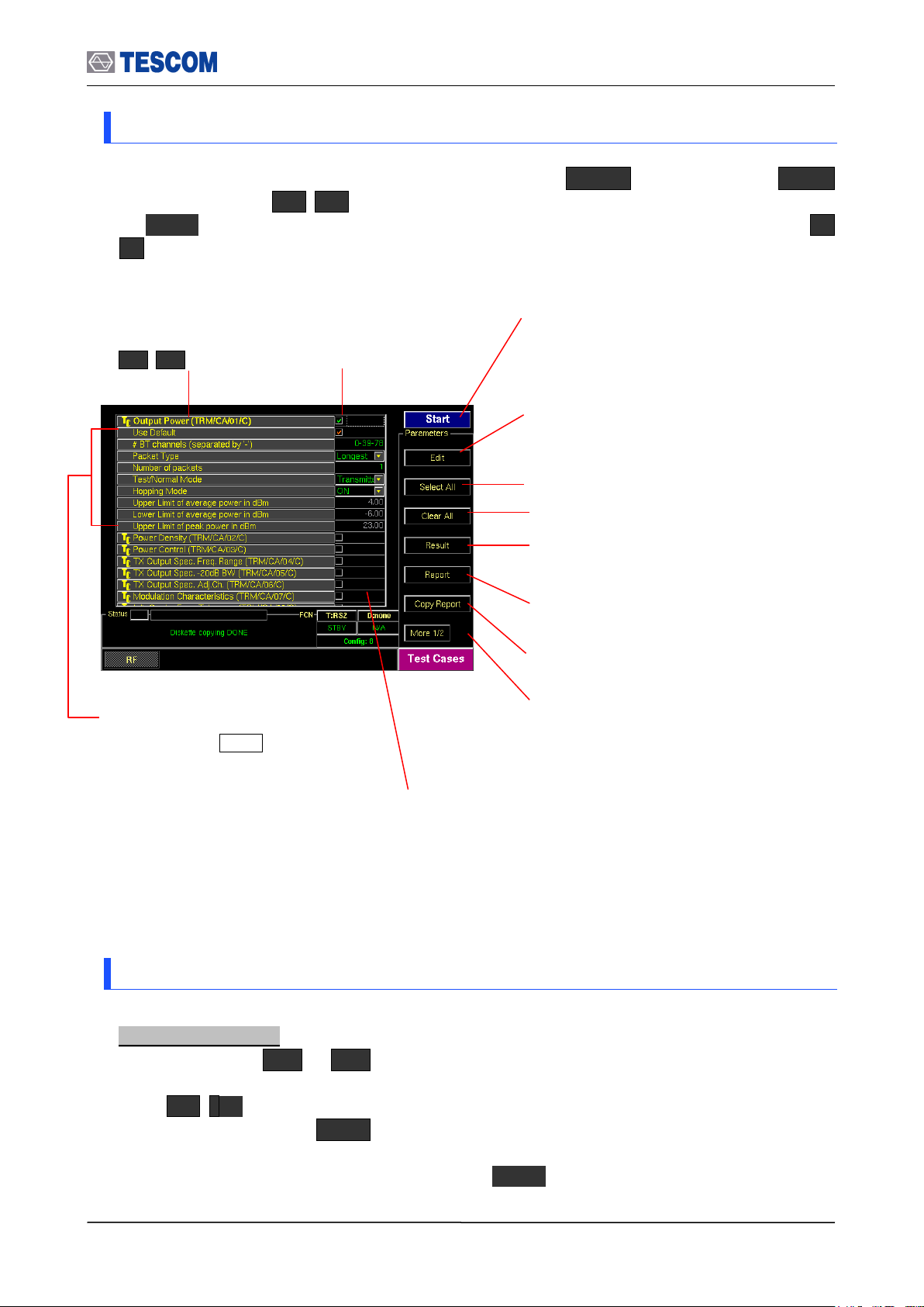
3.8 Operation Procedure (Bluetooth Conformance Test)
Start/Stop: When this menu is pressed the tests
will run once. When pressed again while the
tests are running, the testing will stop.
Edit: When this menu is pressed, you can edit
the various parameters of a highlighted test
case.
Result: Shows the test result of a highlighted
test case.
Report: Shows the report that record test
results and logs from the latest clearing to now.
Copy Report: Copies test cases report to
diskette
Check Box: Indicates if
a test case is selected
or not.
Parameters: This parameters is
displayed when Edit is pressed.
The changing parameter turns the
text color red.
Auto detach: Disconnect DUT after tests are
done automatically.
Status window: Indicates status of test case as follows:
“Run…”: Running the test.
“PASSED”: Pass this test case for test limits set.
“FAILED”: Fail this test case for test limits set.
“Not yet”: Test is not completed.
Test Case: To select test
cases, use Rotary Knob
or keys
Select All: Selects all test case
Clear All: Clear all test case
3.8.1 Step 3. Selecting the Test Cases Screen
Test Cases screen can be accessed by pressing the Menu hard key. Press Menu
Rotary Knob or Select “Test Cases” from the pop-up menu on the screen
ENT . Test cases and parameters can be accessed by using Rotary Knob or
keys.
3.8.2 Step 4. Selecting the Test Cases and Setting Up Test Parameters
Selecting test case:
1) Press soft key ( M1 ~ M5 ) related to a test case screen.
2) Move the box-shaped cursor to a test case that you want to perform using Rotary Knob
or keys.
3) Press Rotary knob or ENT key and confirm that the check box related to the test
case is checked.
4) To unselect test case, press Rotary knob or ENT key again.
71
Page 72

3.8 Operation Procedure (Bluetooth Conformance Test)
NOTE
To apply the changed values to test, “Use Default” must be unchecked. If
“Use Default” is selected, all of displayed values are ignored and the default
values will be assigned automatically.
Changing test parameters:
1) Move the box-shaped cursor to a test case that you want to change test parameters
using Rotary Knob or keys.
2) Press F2 soft key to expand parameter menus.
3) Move the box-shaped cursor to a parameter using Rotary Knob or keys.
4) Push Rotary knob for data input mode. The input cursor indicates data input position or
a drop down menu is driven.
5) Enter the value using keypad or choose the new setting from the drop down menu.
6) Press ENT key.
7) BS key can be used, if necessary during keypad entry.
3.8.3 Step 5. Running the Test Cases and Viewing the Test Results
Pass or fail in results are displayed on the status window related to the test case as soon
as tests are finished. The details of measurement can be shown by two methods,
pressing Result or Report . While the Result screen shows the measures of each test
case, the Report screen displays the measures of all test case performed and test logs
(test conditions, test time, and so on) in a screen. The test report can be copy to 3.5”
diskette by pressing F7 soft key.
Test Result screen:
1) Move the box-shaped cursor to a test case that you want to see results using Rotary
Knob.
2) Press F5 soft key ( Result ), to display the pop-up screen including test results as
below.
Test Report screen:
Press F6 soft key ( Report ), to display the report screen. The report format and mode
can be changed in the Test Configuration screen. (Press Menu Select
“Configuration” from the pop-up menu on the screen M1 (Tester) Press F6 or
F7 .
72
Page 73
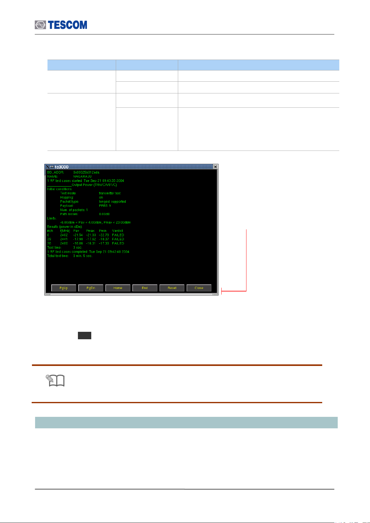
Parameters
Option
Description
Report Format
txt
Text
csv
Coma Separate Value
Report Mode
Overwrite
Overwrite the existing report
Append
Append a new report to the end of existing one. The
buffer size is 10M bytes. Some warning messages are
appeared continuously after the report size is over 1M
bytes. In this case, you should define whether save it to
a diskette or not.
NOTE
Refer to Appendix 2, “RF Test Cases” for details.
PgUp (M1): Page UP
PgDn (M2): Page Down
Home (M3): Go to the home of report
End (M4): Go to the end of report
Reset (M5): Clears the screen
Close (MENU): Closes the screen
Copy the test report to diskette:
1) Insert an USB Memory into USB port on the front panel.
2) Press F7 soft key ( “Copy Report” ).
3) Follow the instruction of the pop-up message.
3.9 Setting up for Bluetooth LE(Low Energy) Testing
3.9 Setting up for Bluetooth LE(Low Energy) Testing
This chapter describes how to set up TC-3000C for Bluetooth LE (Low Energy) Testing. The
3000-50 option should be purchased for BT LE Testing. 3000-20 option should be ordered
together if RF measurement is necessary
You can start BT LE testing by setting the DUT type as “BT LE” in the DUT configuration. All
73
Page 74

3.10 Configuration of the TC-3000C
Parameters
Range
Default
Descriptions
HCI TO (ms)
1 ~ 65535
2000
Timeout of HCI commands execution
Defines a period of time when a Host will wait events from
a Host controller after sending a command. It normally
doesn’t need any modification. If DUT, however, has slow
HCI port then increase the value as much as it is
necessary.
SupervisionTO (s)
1~20
2
Link Supervision Timeout – used for monitoring of link loss
Modulation Index
0.28~0.35
0.32
Modulation Index is the index of FSK modulation
Link before Meas
Passive
Active
Active
Defines whether to activate DUT before starting
measurement or not
Report Format
txt or csv
txt
Defines the format of Test Cases report file; [txt] or [csv]
DUT Type: Select BT LE
method on how to access test screens and set up parameters are same as General Bluetooth
DUT testing.
1) Press MENU key and select the configuration screen.
2) Press M2 (DUT) F2 (DUT Type) .
3) Select “BT LE” from the list.
4) Press MENU key and select a test screen.
3.10 Configuration of the TC-3000C
The TC-3000C is configured in the Configuration function accessed by pressing MENU key.
The configuration screens are used to configure the DUT, the TC-3000C and RF conditions.
The table below represents the configuration parameters for DUT and TC-3000C.
3.10.1 Tester
74
Page 75

3.10 Configuration of the TC-3000C
Report Mode
Append
Overwrite
Append
Defines the save-mode of Test Cases report file; [Append]
or [Overwrite]
BD_ADDR
-
9abc56781234
Bluetooth Device Address of the tester’s Host Controller
Must be entered in little ending format (LSB in the right
side) in hexadecimal notation.
LAP for IAC
9e8b00 ~
9e8b3f
9e8b33
Lower Address Part (3 bytes) of BD_ADDR, from which
the Inquiry Access Code will be derived when the inquiry
procedure is performed; 9e8b33 is GIAC
T inqscan (slts)
18 ~ 4096
2048
Inquiry Scan Interval
Defines the amount of time between consecutive inquiry
scans, i.e., the time interval from the time when the Host
Controller starts its last inquiry scan to the time when it
begins the next inquiry scan.
T winqscan (slts)
18 ~ 4096
512
Inquiry Scan Window
Defines the amount of time for the duration of the inquiry
scan, and T winqscan must be less than or equal to the T
inqscan.
Inq. TO (1.28s)
1 ~ 48
48
Inquiry Timeout
Defines the maximum amount of time specified before the
Inquiry is halted.
# Inq. Responses
0 ~ 16
1
Defines the maximum number of responses from the
Inquiry before the Inquiry is halted; 0 means unlimited
number of responses
T pagescan (slts)
18 ~ 4096
2048
Page Scan Interval
Defines the amount of time between consecutive page
scans, i.e., the time interval from the time when the Host
Controller starts its last page scan to the time when it
begins the next page scan.
T wpagescan (slts)
18 ~ 4096
512
Page Scan window
Defines the amount of time for the duration of the page
scan, and T wpagescan must be less than or equal to the
T pagescan.
Page TO (slts)
1 ~ 65535
16000
Page Timeout
Defines the maximum time the local Link Manager will wait
for a Baseband page response from the remote device at
a locally initiated connection attempt.
If this time expires and the remote device has not
responded to the page at baseband level, the connection
attempt will be considered as failure.
PIN Type
Variable
Fixed
Variable
Defines the type of PIN to be used
PIN Length
0~16 bytes
4
Defines the length of the PIN code (in bytes)
PIN Code
30.30.30.30
Defines the PIN code for the device to be connected; each
byte should be separated by a point. For example, if the
PIN Code is “1234”, type 31,32,33,34
L2CAP TO (ms)
1 ~ 65535
30000
L2CAP Timeout
Defines the timeout of L2CAP commands execution
RFCOMM TO (ms)
1 ~ 65535
30000
RFCOMM Timeout
Defines the timeout of RFCOMM commands execution
75
Page 76

3.10 Configuration of the TC-3000C
SDP TO (ms)
1 ~ 65535
30000
SDP Timeout
Defines the timeout of SDP commands execution
Profile TO (ms)
1 ~ 65535
30000
Profile Timeout
Defines the timeout of Profile commands execution
Skip Pairing
Unchecked
This option will cause the TC-3000C to skip the pairing
process with DUT. To skip pairing, Link Key should be
entered.
Link Key
Specifies Link Keys
AFH
Enable
Disable
Disable
Defines AFH (Adapted Frequency Hopping) enabled.
Enabling this option causes the “Select Channel” menu to
display below.
Select Channel
Selects the AFH channels
Encryption
Enable
Disable
Enable
Defines Encryption enabled in the Tester’s LMP features.
Name Discovery
Checked
Defines whether to read DUT’s name after inquiry
procedure. (When the DUT use Broadcom chip, it is highly
recommended that this parameter is unchecked.
CSR HS1.2
Unchecked
To test CSR Head Set 1.2, check this option. Enabling this
option causes the TC-3000C to skip encryption before
activating test mode.
Friendly Name
Friendly Name is used for easy understandable name (ex
“TC-3000C”) of the device instead of Bluetooth device
address (ex “9ABC56781234”). It could be edited any
name.
Initiate
Authentication
Unchecked
In case of Checked, the Tester will request Authentication
procedure from the DUT.
Delay for TC
1 ~ 65535
ms
Time delay between Test mode setting using LMP
message and real measurement in Test case
Pause test
Unchecked
When you send a message about the control to the DUT
in the TC-3000C, you can set whether or not to use the
‘PAUSE’ between the message and the message. In case
of Checked, Pause between the message and the
message.
BCM20780
Unchecked
Check if you want to test ‘BCM 20780’ chip of ‘Broadcom’
76
Page 77

3.10.2 DUT
Parameters
Range
Default
Descriptions
DUT Type
General
BT
BT Le
BT
Type of DUT
To perform general RF measurements, select
General.
HCI Port
None
USB1
USB2
RS1
RS2
UART1
UART2
BCSP1
BCSP2
2WIRE1
2WIRE2
Type of HCI port
If DUT has HCI port, select the type of it. Otherwise
select None. If UART selected, determine the Baud
Rate.
If DUT is plugged into HCI port of TC-3000C in
Preparation, the type of port will be automatically
selected.
This parameter MUST NOT be the same as HCI port
setting of Tester.
error stop TC
-
Checked
Defines whether to stop the Test Cases when an error
occurs during execution
Num. of recover
0 ~ 10
0
Defines the number of attempts to recover the link lost
while Test Cases are running
Path Loss (dB)
0 ~ 80
0
Defines the amount of the power loss in the full path
between Tester and DUT (in dB)
Inq. supported
-
Checked
Flag indicating whether the DUT supports inquiry
When Bluetooth devices want to make a connection
between them, they take two steps: Inquiry and Page.
Master (Tester) gets the BD_ADDR of slave (DUT) in
Inquiry procedure and then uses it in Page procedure.
If you want to test according to the above two
procedures, let this box checked. But if you already
know BD_ADDR of DUT, uncheck this box and write
down parts of BD_ADDR of DUT in LAP for DAC.
Then it will start from Page.
LAP for IAC
9e8b00 ~
9e8b3f
9e8b33
Lower Address Part (3 bytes) of BD_ADDR, from
which the Inquiry Access Code will be derived when
the inquiry procedure is performed; 9e8b33 is GIAC
T inqscan (slts)
18 ~ 4096
2048
Inquiry Scan Interval
Defines the amount of time between consecutive
inquiry scans, i.e., the time interval from the time
when the Host Controller starts its last inquiry scan to
the time when it begins the next inquiry scan.
T winqscan (slts)
18 ~ 4096
18
Inquiry Scan Window
Defines the amount of time for the duration of the
inquiry scan, and T winqscan must be less than or
equal to the T inqscan.
Inq. TO (1.28s)
1 ~ 48
48
Inquiry Timeout
Defines the maximum amount of time specified before
the Inquiry is halted.
# Inq. Responses
0 ~ 16
1
Defines the maximum number of responses from the
Inquiry before the Inquiry is halted; 0 means unlimited
number of responses
3.10 Configuration of the TC-3000C
77
Page 78

3.10 Configuration of the TC-3000C
BD_ADDR
-
0
Bluetooth Device Address of the DUT
Must be entered in little ending format (LSB in the
right side) in hexadecimal notation.
6 bytes Bluetooth Device Address of the DUT, from
which the Device Access Code will be derived when
the page procedure is performed; the parameter is
used only when ‘Inq. supported’ is not checked
T pagescan (slts)
18 ~ 4096
2048
Page Scan Interval
Defines the amount of time between consecutive page
scans, i.e., the time interval from the time when the
Host Controller starts its last page scan to the time
when it begins the next page scan.
T wpagescan (slts)
18 ~ 4096
18
Page Scan window
Defines the amount of time for the duration of the
page scan, and T wpagescan must be less than or
equal to the T pagescan.
Page TO (slts)
1 ~ 65535
16000
Page Timeout
Defines the maximum time the local Link Manager will
wait for a baseband page response from the remote
device at a locally initiated connection attempt.
If this time expires and the remote device has not
responded to the page at baseband level, the
connection attempt will be considered as failure.
Pow. SetTime (ms)
1 ~ 65535
1000
Power setting time of DUT
Defines the interval of time Tester must wait until the
DUT will reach the new power step.
Conn. for Test
Checked
Defines whether LMP connection should be created
before activating DUT’s test mode
Test Mode
NULL Pkt
Transmitter
Loopback
Loopback
Defines the test mode to be used in activating DUT’s
test mode; NULL pkt means simple connection
Bit Pattern
0000 0000
1111 1111
1010 1010
1111 0000
PRBS9
10101010
Bit pattern of payload
PRBS : Pseudo Random Binary Sequence
Defines the bit pattern of a payload to be used in the
test mode
Whitening
Disable
Enable
Disable
Enable/Disable of Whitening
Defines whether to scramble the packets with the
whitening sequence or not in the loopback test mode
Hopping Mode
ON
OFF
OFF
tx:0
rx:0
Defines whether to use 79 hopping sequence or not in
the test mode; for ‘Off’, select the TX and RX
channels respectively
78
Page 79

Packet Type
DM1, DH1
HV1, HV2
HV3, AUX1
DM3, DH3
DM5, DH5
EV3, EV4
EV5, 2-DH1
3-DH1, 2-DH3
3-DH3, 2-DH5
3-DH5, 2-EV3
3-EV3, 2-EV5
3-EV5
2-DM1
Defines the type of packet to be used in the test mode
Length (bytes)
0 ~ MAX
MAX
Defines the length of a payload to be used in the test
mode (in bytes). MAX is changed according to Packet
Type
Parameters
Range
Default
Descriptions
TX Power (dBm)
-80 ~ 0
0
Defines TX power of the Tester. Prohibited to change if
any ACL link exists
RX Attenuator
On
Off
Off
Defines the setting of the RX attenuator of the Tester;
The dynamic range of Tester’s receiver is –80 ~ -10
dBm for ‘On’, but –30 ~ +20 dBm for ‘Off’
AGC
On
Off
On
Automatic Gain Control Setting of Tester Controls IF
power level inside Tester’s receiver.
RX Power (dBm)
10 ~ 70
-
Defines the input range of the Tester’s receive available
only in case AGC is Off
10MHz Ref.
Int
Ext
Int
Defines whether 10MHz Reference Oscillator is internal
or external
Parameters
Range
Default
Descriptions
Ext Outport 1
I-RX, Q-RX,
I-TX, Q-TX,
RX bit, RX clk
TX bit, TX clk
FSK Demod,
FSK Mod,
RX Mag,
Audio, Loop Back
FSK Demod
Defines the signal going out through the
BASEBAND OUT port 1 on the front panel. During
operation, you can see the Baseband signals by
connecting to oscilloscope.
If you want to make a connection through
Baseband, not RF, select what you want.
3.10.3 RF Settings
3.10 Configuration of the TC-3000C
3.10.4 Peripherals
79
Page 80

Ext Outport 2
See Ext Outport 1
FSK Mod
Defines the signal going out through the
BASEBAND OUT port 2 on the front panel
Ext Inports
1:Off 2:Off
1:I-TX 2:Q-TX
1:Off
2:Off
Defines the signal coming in through the
BASEBAND IN ports 1 and 2 on the front panel. By
default, it must be “1:Off 2:Off” if you will connect
through RF.
If you want to make a connection through
Baseband, not RF, select what you want.
Color Scheme
Dark
B-W
Dark
Defines the color scheme to be used for Tester’s
screen
Use mouse
Unchecked
Defines whether to use the mouse or not
Set Time
Sets the date and time of the system
System Info
See the system information; Serial Number, Version,
Software Options.
Parameters
Range
Default
Descriptions
TC-3000 IP
IP address of the Tester
Remote IP
IP address of a remote PC
Netmask
Subnet mask
Gateway
Gateway
Remote Ctrl
Unchecked
To enable the control from a remote PC, check this box and
reboot Tester.
Port
None
RS1
RS2
RS1
TC-3000C is equipped with two serial RS-232C interfaces.
The settings None, RS1, or RS2 are allowed.
Baudrate
115200
TC-3000C allows baud rates between 2400 and 115200
baud to be set.
Data bit
5,6,7,8
8
Data transmission is in the 5, 6, 7, or 8 bit ASCII code,
starting with the least significant bit (LSB).
Parity
None
Odd
Even
None
A parity bit can be transmitted for error protection. The
settings No parity, even or odd parity are allowed.
Stop Bit
1,2
1
Transmission of a data byte is terminated by one or two
stop bits.
Flow Ctrl
None
RTSCTS
RTSCTS
Define Flow Control. The settings None or RTSCTS
(Request To Send, Clear To Send) are allowed.
Upgrade IP
64.33.6.108
IP address of FTP server for upgrading software.
Upgrade S/W
Upgrades the software from USB Memory
3.10.5 Network
3.10 Configuration of the TC-3000C
80
Page 81

3.11 General Purpose Communication Analyzer
Parameters
Range
Default
Frequency
2.4~2.5 GHz
2.45 GHz
Power
-80~0 dBm
0
Bit Pattern
0 ~ 0×FFFFFFFF
55555555
FM Deviation
0~1000 kHz
150
0 × 00000000
0 × FFFFFFFF
0 × 55555555
0 × F0F0F0F0
Frequency: Set Carrier frequency.
Range: 2.4 ~ 2.5 GHz
Power: Set RF output level.
Range: -80 ~ 0 dBm
Bit Pattern : Set FSK modulation Pattern
Range: 0 ~ 0×FFFFFFFF
FM Deviation: Set FM deviation.
Range: 0 ~ 1000 kHz
Start/Stop: When this menu is pressed the
modulated signal will be transmitted. When the
menu is pressed again while the signal is
transmitting, the transmission will stop.
3.11 General Purpose Communication Analyzer
3.11.1 Signal Generator
TC-3000C provides a general purpose RF source for ISM band receiver test.
Measurement can be accessed by pressing the Menu hard key. Press Menu
Rotary Knob or ,
Select “SigGen” from the pop-up menu on the screen ENT
[Table 5] Pattern Example
81
Page 82
3.11 General Purpose Communication Analyzer
Parameters
Range
Default
Center
2.4~2.5 GHz
2.45
Span (MHz)
1, 1.25, 2, 2.5, 5, 10
10
Num of sweeps
1 ~ 50
1
Trace Mode
Average / Maxhold
Average
Ref. Level (dBm)
-80 ~ 40
-80 + Path Loss ~ 40 + Path Loss
dB/Div
1 ~ 20
10
Detector
Peak / Average
Peak
Sweep Time (ms)
0.1~3.2
0.1
Parameters
Range
Default
Frequency
2.4~2.5 GHz
Freq/Div (kHz)
10 ~ 1000
100
1 MHz Filter
Checked
Start Time (us)
-70 ~ 624
-15
Time(us)/Div
0.1 ~ 60
10
3.11.2 Signal Analyzer
TC-3000C provides general purpose RF signal analyzer for ISM band transmitter test. In this
mode you can use Spectrum, FM Modulation and Power-Time screen in Measurement
function.
1) To set the TC-3000C to general test mode, press Menu Select “Configuration”
from the pop-up menu on the screen M2 (DUT) press F1 (DUT Type) and
select “General” from the drop down lists.
2) To access “Measurement’’ function, press Menu Select “Measurement” from the
pop-up menu on the screen ENT
3) To access Spectrum, FM Modulation, or Power-Time screen, press M1 , M2 , or M3
key.
Operations are the same as the test screens in Bluetooth test mode except parameters
below.
M1 (Spectrum) F8 F2 (Detector): Allows you to select detector modes,
which include Peak or Average. Peak mode is good for seeing signals that are very
close to the noise floor. Average mode is the default mode.
M1 (Spectrum) F8 F3 (Sweep time (ms)): Specifies the 0.1 to 3.2 ms
Sweep time.
Frequency: Specifies the 2.4 to 2.5 GHz frequency.
Spectrum
FM Modulation
82
Page 83
3.12 Store/Recall/Preset Instrument Settings
Parameters
Range
Default
Frequency
2.4~2.5 GHz
Ref. Level (dBm)
-80 ~ 40
-80 + Path Loss ~ 40 + Path Loss
dB/Div
1 ~ 20
10
1 MHz Filter
Checked
Time(us)/Div
0.1 ~ 60
NOTE
Refer to Appendix C “The list of Save/Recall parameters” for details
Power vs. Time
3.12 Store/Recall/Preset Instrument Settings
The SAVE and Recall functions allow you to store different instrument setups and retrieve
them later. By saving test setups, you can save time by eliminating the task of re-configuring
the TC-3000C and DUT.
The Preset function restores the default settings (register number 8).
SAVE
1) Make any changes to the instrument that you want to SAVE in a register.
2) Press FCN + Recall .
3) Push Rotary Knob and select a register number (0 through 7).
4) Press the Knob or ENT key.
Recall
1) Press Recall key.
2) Push Rotary Knob and select a desired register number.
3) Press the Knob or ENT key.
Preset
1) Press FCN + INCR SET .
2) Select “Yes” and Press ENT key.
3.13 Checking List for Common Problems
This section provides a brief check lists of common failures. Before troubleshooting or repairing the
TC-3000C, make sure the failure is in the instrument rather than any external connections. Also
make sure that the instrument is accurately calibrated.
83
Page 84

3.13 Checking List for Common Problems
3.13.1 Unit is inoperative
1. Verify that the AC power cord is connected to the TC-3000C
Make sure that the power cord is firmly plugged into the power module on the rear
panel. You should also make sure that the power source you plugged the TC-3000C
into is energized.
2. Verify that the front-panel power switch is depressed.
Verify that the TC-3000C’s power switch is in the “I” position.
3. Verify line voltage.
The available line voltage is 100 ~ 240 VAC
3.13.2 Failure of testing
1. Check whether Host and Host Controller of TC-3000C is connected with USB
or RS-232C cable.
2. Check primary parameters:
- Configuration DUT HCI Port
- Configuration DUT Path Loss
- Configuration Tester PIN code
- Configuration DUT Test Mode
- Configuration DUT DUT Type
3. Check Level.
If the RF level is lower or higher than the receiver sensitivity allows, the DUT may
not respond.
4. Check if DUT is set to Inquiry/Page scan mode
84
Page 85

This section contains information for keeping the instrument in good working
order and checking its overall performance.
Chapter
4
Performance Test
4.1 General Information
The procedures in this chapter allow the verification of the electrical performance of TC3000C. It contains procedures suitable for determining if TC-3000C functions, is adjusted
properly, and meets the performance characteristics as warranted. These tests do not
require access to the interior of the instrument.
The set-up drawings at the beginning of each test procedure show the test configuration
needed for each test. To perform the test procedures you need to know basic TC-3000C
operation. You should be familiar with the front panel, the various test screens, and knob
operation. The test procedures give critical instrument settings and connections, but they
don’t tell the manufacture test specification.
Page 86

2.6 Cleaning, Storage and Shipment
Description
Minimum specification
Model
Power meter
-20 to 27dBm, 100 kHz to 4 GHz
HP-437B/8482A
Spectrum analyzer
100 kHz to 6.5 GHz, up to –120 dBm
HP-8561E
Measuring receiver
0.15 to 1300 MHz, 0 to –130dBm, Freq Counter
HP-8902A
Signal Generator
100 kHz ~ 1 GHz, +/- 0.5 dB, +20 ~ -120 dBm
HP-8648C
Frequency Counter
+/- 0.1 ppm, 10 Hz ~ 3 GHz, 9 digit
HP-53181A
Sensor Module
50 ohm, 10 uW ~ 1W
HP-11722A
Mixer
VSWR <= 1.2, with 10 dB attenuator
Mini-Circuits, JCIR-25
NOTE
Unless otherwise noted, a warm-up period of 2 hours is required for these tests.
4.1.1 Recommended test equipment
Equipment required for the performance tests is listed in below table. Any equipment that
satisfies the critical specifications in the table may be substituted for the recommended
model.
The performance tests are based on the assumption that the recommended test
equipment is used. Substituting alternate test equipment may require modification of
some procedures.
4.1.2 Calibration Cycle
This instrument requires periodic verification of performance. Depending on the use and
environmental conditions, the instrument should be checked using the following
performance tests at least once every year.
86
Page 87
2.6 Cleaning, Storage and Shipment
NOTE
Before perform the tests, TC-3000C should be initialized as follow procedure.
In the signal generator mode, the cable loss is ignored (Path Loss = 0).
TC-3000C
FREQUENCY COUNTER
RF IN/OUT
RF INPUT
4.1.3 TC-3000C Initial Set Up
1) Power on
2) Allow 2 hour warm-up time for the TC-3000C
3) Press MENU key Select “Configuration” from pop-up menu
4) Press M2 (DUT)
5) Press F2 (DUT Type) Select “General” from pop-up menu
6) Press F7 (Path Loss) Set “Path Loss” by the cable loss. (Typically, RG400
cable loss is 1dB/m)
7) Press M3 (RF Settings)
8) Press F4 (AGC) Select “ON”
9) Press F3 (Rx Attenuator) Select “30dB”
4.2 Signal Generator
4.2.1 Frequency Accuracy
Specification: 2496 MHz 1 ppm
Equipment: Frequency Counter, HP53181A
1. Test Setup : Connect equipment as shown in the figure below
[Figure 5] Carrier frequency accuracy test
2. Set controls of TC-3000C as follows :
Set TC-3000C to “Signal Generator” mode. ( MENU Select “SigGen”)
- Frequency: 2496 MHz
- Power: 0dBm
- Bit Patten: 0
- FM Deviation: 0
3. Press “Start” to begin the test and read the frequency from the frequency counter.
87
Page 88
2.6 Cleaning, Storage and Shipment
Fc
Spectrum
Marker
2400 MHz
2420 MHz
2440 MHz
2460 MHz
2480 MHz
2500 MHz
Spec.
Spec.
Spec.
Spec.
Spec.
Spec.
Fc-300kHz
<=-
31dBm
<=-
31dBm
<=-
31dBm
<=-
31dBm
<=-
31dBm
<=-
31dBm
Fc-150kHzt
<=-
31dBm
<=-
31dBm
<=-
31dBm
<=-
31dBm
<=-
31dBm
<=-
31dBm
Fc
1>=, >=-1
1>=,
>=-1
1>=,
>=-1
1>=,
>=-1
1>=,
>=-1
1>=,
>=-1
Fc+150kHz
<=-
31dBm
<=-
31dBm
<=-
31dBm
<=-
31dBm
<=-
31dBm
<=-
31dBm
Fc+300kHz
<=-
31dBm
<=-
31dBm
<=-
31dBm
<=-
31dBm
<=-
31dBm
<=-
31dBm
TC-3000C
2450 MHz
INPUT 50
HP 8561E
4.2.2 I/Q modulation calibration
Equipment: Spectrum Analyzer, HP8561E
1. Test Setup: Connect equipment as shown in the figure below
[Figure 6] I/Q modulation calibration test
2. Set controls of TC-3000C as follows:
Set TC-3000C to “Signal Generator” mode. ( MENU Select “SigGen”)
- Power: 0dBm
- Bit Patten: 0
- FM Deviation:150 kHz
3. Set controls of Spectrum Analyzer as follows:
Span: 1 MHz
RBW: 10 kHz
VBW 210 kHz
4. Set TC-3000C output frequency according to the table below. At each setting,
press “Start” ( F1 ) to begin the test.
5. Record the level in the table for each setting. The limits for this frequency are
given in the table.
88
Page 89

2.6 Cleaning, Storage and Shipment
TC-3000C
2450MHz
INPUT 50
HP 8561E
4.2.3 PLL phase noise
Equipment: Spectrum Analyzer, HP8561E
Specification: M1=0 dBm, M2 <= -60 dBm
1. Test Setup: Connect equipment as shown in the figure below
[Figure 7] PLL phase noise test
2. Set controls of TC-3000C as follows:
Set TC-3000C to “Signal Generator” mode. ( MENU Select “SigGen”)
- Frequency: 2450 MHz
- Power: 0dBm
- Bit Patten: 0
- FM Deviation: 0
3. Set controls of Spectrum Analyzer as follows:
Center Frequency: 2450 MHz
RBW: 30 kHz
VBW 3 kHz
4. Press “Start” ( F1 ) to begin the test.
5. Record the center frequency level (M1) on the spectrum analyzer.
6. Record the center frequency + 500KHz level (M2) on the spectrum analyzer.
89
Page 90

2.6 Cleaning, Storage and Shipment
8902A
INPUT 50
IF
LO
R
TC-3000C
HP 8648C
RF OUTPUT
70 MHz IF
+13 dBm
2450 MHz
2380 MHz
10dB Attenuator
70MHz BPF
4.2.4 FM accuracy
Equipment: Spectrum Analyzer, HP8561E
Signal Generator, HP 8648C
Mixer
Specification: 140 kHz ±10 kHz at rms FM demodulation. filter : 20 Hz ~ 200 kHz
1. Test Setup: Connect equipment as shown in the figure below
[Figure 8] FM accuracy test
2. Set controls of TC-3000C as follows:
Set TC-3000C to “Signal Generator” mode. ( MENU Select “SigGen”)
- Frequency: 2450 MHz
- Power: 0dBm
- Bit Patten: FFFF0000
- FM Deviation: 150
3. Press “Start” ( F1 ) to begin the test.
4. Record the FM demodulation on the HP8902.
90
Page 91

2.6 Cleaning, Storage and Shipment
Frequency
Level
2400 MHz
2420 MHz
2440 MHz
2460 MHz
2480 MHz
2500 MHz
0 dBm
8902A
INPUT 50
IF
LO
R
TC-3000C
HP 8648C
RF OUTPUT
70MHz IF
+13dBm
2450MHz
2380MHz
POWER METER
sensor
10dB Attenuator
70MHz BPF
Sensor
Module
4.2.5 Output level accuracy test
Equipment: Spectrum Analyzer, HP8561E
Signal Generator, HP 8648C
Mixer
Power Sensor
Specification: Power error <= ±1 dB
1. Test Setup: Connect equipment as shown in the figure below
[Figure 9] Output level accuracy test
2. Set controls of TC-3000C as follows:
Set TC-3000C to “Signal Generator” mode. ( MENU Select “SigGen”)
- Frequency: 2400 MHz
- Power: 0dBm
- Bit Patten: 0
- FM Deviation: 0
3. Connect the power sensor to TC-3000C
4. Set TC-3000C output frequency and level according to the table below. At each
setting, press “Start” ( F1 ) to begin the test.
5. Record the power in the table for each setting.
91
Page 92
2.6 Cleaning, Storage and Shipment
Frequency
Level
2400 MHz
2420 MHz
2440 MHz
2460 MHz
2480 MHz
2500 MHz
0 dBm
0dB
ref
0dB
ref
0dB
ref
0dB
ref
0dB
ref
0dB
ref
-20 dBm
-40 dBm
-60 dBm
-80 dBm
TC-3000C
HP 8648C
6. Remove the power sensor and connect the TC-3000C to the mixer.
7. Be sure that the measuring receiver is calibrated in Turned RF mode.
8.Set TC-3000C output frequency and level according to the table below. Set the RF
frequency of the HP 8648C to equal the TC-3000C output frequency minus 70MHz.
At all 0dBm level settings, set the readings on the HP 8902A to the ratio reference
for subsequent measurements by pressing “RATIO” key. At each setting, press
“Start” ( F1 ) on the TC-3000C to begin the test.
9. Record the power in the table for each setting.
4.3 Testing Receiver
4.3.1 Power measurement accuracy
Equipment: Signal Generator, HP8648C
Specification:
- Power measurement error : <= ±1.0 dB at +20 dBm ~ -30 dBm , RX Attenuator 0
dBm
- Power measurement error : <= ±1.0 dB at –10 dBm ~ -80 dBm , RX Attenuator 30
dBm
1. Test Setup: Connect equipment as shown in the figure below
[Figure 10] Power measurement accuracy test
92
Page 93

2.6 Cleaning, Storage and Shipment
2400 MHz
2420 MHz
2440 MHz
2460 MHz
2480 MHz
2500 MHz
-10 dBm
-20 dBm
-30 dBm
-40 dBm
-50 dBm
-60 dBm
-70 dBm
-80 dBm
2400 MHz
2420 MHz
2440 MHz
2460 MHz
2480 MHz
2500 MHz
+14 dBm
+10 dBm
0 dBm
-10 dBm
-20 dBm
-30 dBm
-40 dBm
-50 dBm
2. Set controls of TC-3000C as follows:
Make sure “RX Attenuator” is 0 dB. ( MENU Select “Configuration” M3
F3 )
Set TC-3000C to ”Pow-Time” screen mode. ( MENU Select “Measurement”
M3 )
- Ref. Level: 0dBm
3. Set Signal Generator output frequency and level according to the table below. At
each setting, set TC-3000C input frequency according to the signal generator output
frequency.
4. Record Pav (average power) in the table for each setting.
5. Change controls of TC-3000C as follows:
Set “RX Attenuator” to 30 dB. ( MENU Select “Configuration” M3 F3 )
Set TC-3000C to ”Pow-Time” screen mode. ( MENU Select “Measurement” M3 )
- Ref. Level: 20 dBm
6. Set Signal Generator output frequency and level according to the table below. At
each setting, set TC-3000C input frequency according to the signal generator output
frequency.
7. Record Pav (average power) in the table for each setting.
93
Page 94

2.6 Cleaning, Storage and Shipment
TC-3000C
50 Terminator
4.3.2 Maximum sensitivity
Specification: Maximum value <= -100 dBm @ resolution BW = 40 kHz
1. Test Setup: Connect equipment as shown in the figure below
[Figure 11] Maximum sensitivity test
2. Set controls of TC-3000C as follows:
Make sure “RX Attenuator” is 0dB. ( MENU Select “Configuration” M3 F3 )
Set TC-3000C to ”Spectrum” screen mode. ( MENU Select “Measurement”
M1 )
- Frequency: 2450 MHz
- Ref. Level: -50 dBm
- Span: 10 MHz
- Num of sweeps: 50
3. Read the peak level on the screen.
94
Page 95

2.6 Cleaning, Storage and Shipment
SG output frequency
Peak Power
Specification
2445 MHz
<= -10 dBm ± 4 dB
2446 MHz
<= -10 dBm ± 4 dB
2447 MHz
<= -10 dBm ± 1 dB
2448 MHz
<= -10 dBm ± 1 dB
2449 MHz
<= -10 dBm ± 1 dB
2450 MHz
<= -10 dBm ± 1 dB
2451 MHz
<= -10 dBm ± 1 dB
2452 MHz
<=-10 dBm ± 1 dB
2453 MHz
<=-10 dBm ± 1 dB
2454 MHz
<=-10 dBm ± 4 dB
2455 MHz
<= -10 dBm ± 4 dB
TC-3000C
HP 8648C
4.3.3 Gain Roll-off
Equipment: Signal Generator, HP8648C
1. Test Setup: Connect equipment as shown in the figure below
[Figure 12] Gain Roll-off test
2. Set controls of TC-3000C as follows:
Set TC-3000C to ”Pow-Time” screen mode. ( MENU Select “Measurement”
M3 )
- Frequency: 2450 MHz
- Ref. Level: 0 dBm
- 1.3 MHz Filter: OFF
- Time(us)/Div: 15
3. Set Signal Generator output level to –10 dBm
4. Set Signal Generator output frequency according to the table below. At each
setting, read Peak power on the TC-3000C and record the level in the table. The
limits for this frequency are given in the table.
95
Page 96

There are two major ways to control TC-3000C remotely. One is to use Dynamic Link Library
(DLL) file in order to make your own Bluetooth test application programs. The DLL provided by
TESCOM is used to communicate with TC-3000C through TCP/IP, USB, or RS-232C interface.
And it is independently supplied in accordance with firmware version of TC-3000C. Another is to
use RS-232C commands without any other additional file contrary to the DLL.
Programming Guide
Chapter
5
Page 97
5.1 Introduction
Windows
Applition
Host Controller
Host
Linux
Application
TCP/IP
TCP/IP
Call Functions
Host(DLL)
TC-3000C
Remote PC(User)
5.1 Introduction
The purpose of this chapter is to help you develop test applications of your Bluetooth product
in the test executive you intend to use. TC-3000C supports Ethernet(Host) / USB(Host
Controller) / RS-232C(Host, Host Controller) port located at the rear panel for remote
operation under PC control.
System Requirements: To develop test applications, your development platform should
meet the following requirement.
Operating System: Microsoft Windows 98, ME, 2000, XP.
Development Tool: Microsoft Visual C++.NET, Visual C++, Visual Basic, Boland C++
Bulider, National Instrument LabWindows/CVI, LabView, etc
Support scope: You can control following functions of TC-3000C.
Test Configuration
RF Test Case
Measurement(DLL only)
Audio Test
5.2 Getting Started
Take a closer look at two kinds of TC-3000C remote control method. One is to use Dynamic
Link Library (DLL). According to your need you can choose and use Ethernet(Host), USB(Host
Controller) or RS-232C(Host Controller) port. And you are able to call some functions of
DLL(“tc3k.dll”) for your testing goal. By the way, you have a trouble controlling two or more TC3000Cs in this case. That is why DLL containing Host program occupies most of CPU
resources of your PC like the following figures.
Remote control diagram using Ethernet (Host)
97
Page 98
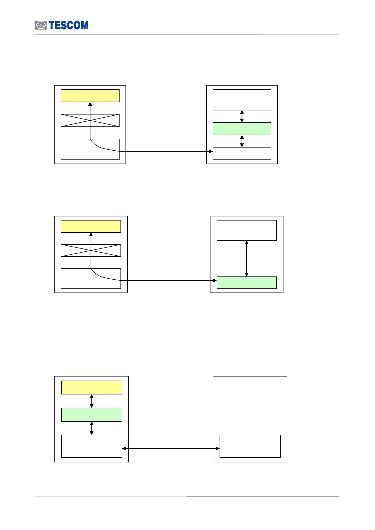
5.2 Getting Started
Windows
Applition
Host Controller
Host
Linux
Application
USB
(Host Controller)
USB
Call Functions
Host(DLL)
USB Driver
TC-3000C
Remote PC(User)
Windows
Applition
Host Controller
Host
Linux
Application
RS-232C
(Host Controller)
RS-232C
Call Functions
Host(DLL)
TC-3000C
Remote PC(User)
Windows
Applition
Host Controller
Host
Linux
Application
RS-232C
RS-232C
Command/Response
TC-3000C
Remote PC(User)
Remote control diagram using USB (Host Controller)
Remote control diagram using RS-232C (Host Controller)
Another is to send RS-232C commands. At present, you can utilize the command through
only RS-232C(Host) port. In this case, you don’t have any limitation to control several TC3000Cs at the same time contrary to DLL.
Remote control diagram using RS-232C (Host)
In order to successfully perform the remote control, the following configuration settings need to be done.
98
Page 99
5.2 Getting Started
NOTE
Make sure the Local IP and Remote IP is correct on the above screen.
LAN Remote Contorl Mode
Version : 1.16 04-09-22
Boot time : 08:28:38 10/29/2004
Local_IP : 10.52.147.70
Remote_IP : 10.52.147.71
i
Quit
Quit
With Switch to Normal Mode
5.2.1 Settings for Ethernet(Host) remote control using DLL
1. Setting up Netwok Parameters: Press Menu Select “Configuration” from the pop-up
menu on the screen M5 (Network) Setting up Network Parameters
2. Enable Remote Control: Press F7 on the above screen to set Remote Ctrl to
“Checked”.
3. Reboot TC-3000C.
4. If you have the following screen, the setting has been done successfully.
5. Execute “PING” command on you PC so as to see if TC-3000C is operating and also to
see if network connections are intact.
6. Call the following functions in your application to make Ethernet remote control program
using DLL.
(1) write_tester_hci_tl(16); // TCP/IP : 16
(2) write_local_ip(“10.52.147.71”); // “Local IP” of user PC is “Remote IP” of TC-3000C.
(3) wirte_remote_ip(“10.52.147.70”); // “Remote IP” of user PC is “Local IP” of TC-3000C
5.2.2 Settings for USB(Host Controller) remote control using DLL
1. Copy following files to your system directory.
Files required : tc_terter.sys, tc_tester.inf
System Directory : C:/WINDOWS/system32(Windows XP)
2. Connect USB port of TC-3000C Host Controller with USB port of your PC, and then use
the “Found New Hardware Wizard”. Even If our driver has not passed Windows Logo
testing, Ignore it and push the “ContinueAnyway” button. Our driver will be installed
successfully.
3. Call the following functions in your application to make USB remote control program
using DLL.
99
Page 100

5.2 Getting Started
FAILED to autodetect connection to DSP
Your choice :
- check cable, and click Retry,
- or, click Quit to shutdown
Retry
Quit
READ:SERIAL_NUM?
3000C2A0023
EXEC:RESET
OK
Log hide
Local
PgUp
PgDn
Home
End
Change remote mode to local mode
Hide all commands and responses
(1) write_tester_hci_tl(1); // 1:USB
(2) write_tester_hc_port(0); // 0:USB1
5.2.3 Settings for RS-232C(Host Controller) remote control using DLL
1. The supplied RS-232C cable is used to connect RS-232C port of TC-3000C Host
Controller with serial port of user PC.
2. Turn on TC-3000C.
3. Call the following functions in your application to make RS-232C remote control program
using DLL.
(1) write_tester_hci_tl(2); // 2: RS-232C
(2) write_tester_hc_port(0); // 0 : COM1
5.2.4 Settings for the RS-232C(Host) remote control without using DLL
1. Setting up RS-232C Parameters: Press Menu Select “Configuration” from the pop-
up menu on the screen M5 (Network) F8 (More 1/3) Setting up RS-232C
Parameters.
2. You can ascertain whether your RS-232C settings including cable connection state is
correct through Hyper Terminal on your PC.
3. If your RS-232C settings are right, the screen of TC-3000C will be changed as follows.
100
 Loading...