

Tescom ER1200 Series, ER1200-1-1, ER1200-1, ER1200-2, ER1200-2-1 Operation & Service Manual
Page 1

Form # 1925 Rev. 4/06 TESCOM
TABLE OF CONTENTS
Page
GENERAL OPERATION
ER1200 Versions . . . . . . . . . . . . . . . . . . . . . . . . . . . . . . . . . . . . . . . . . . . 1
Introduction . . . . . . . . . . . . . . . . . . . . . . . . . . . . . . . . . . . . . . . . . . . . . . . . 1
Internal Feedback Mode . . . . . . . . . . . . . . . . . . . . . . . . . . . . . . . . . . . . . . 1
External Feedback Mode . . . . . . . . . . . . . . . . . . . . . . . . . . . . . . . . . . . . . 2
SPECIFICATIONS . . . . . . . . . . . . . . . . . . . . . . . . . . . . . . . . . . . . . . . . . . 3
ELECTRICAL INSTALLATION . . . . . . . . . . . . . . . . . . . . . . . . . . . . . . . 3-4
ER1200 CONFIGURATION
Configure Setpoint Signal . . . . . . . . . . . . . . . . . . . . . . . . . . . . . . . . . . . . 5
Configure Analog Output Signal . . . . . . . . . . . . . . . . . . . . . . . . . . . . . . . . 5
Configure Feedback Signal . . . . . . . . . . . . . . . . . . . . . . . . . . . . . . . . . . . 5
TUNING THE ER1200
Deadband . . . . . . . . . . . . . . . . . . . . . . . . . . . . . . . . . . . . . . . . . . . . . . . . . 6
Zero & Span . . . . . . . . . . . . . . . . . . . . . . . . . . . . . . . . . . . . . . . . . . . . . 6-7
Gain & Stability . . . . . . . . . . . . . . . . . . . . . . . . . . . . . . . . . . . . . . . . . . . . . 7
TROUBLE SHOOTING . . . . . . . . . . . . . . . . . . . . . . . . . . . . . . . . . . . . . . 8
ER1200
Operations &
Service Manual
Page 2
Form # 1925 Rev. 4/06 TESCOM
1
GENERAL OPERATION
INTRODUCTION
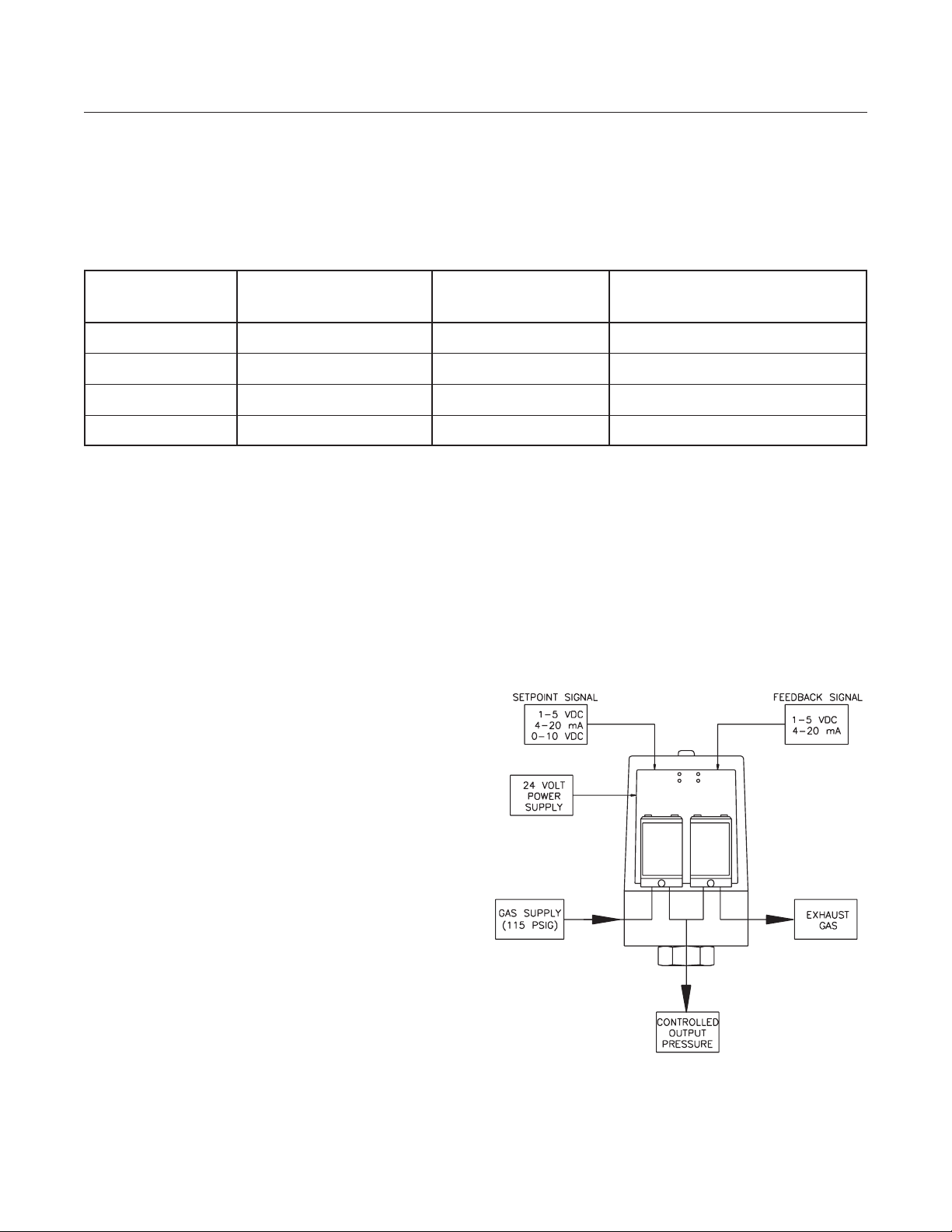
The ER1200 is a closed loop pressure control system capable of operating in two different modes.
In the “Internal Feedback” mode, the control is based on the internal pressure sensor, which has a
range of 0 - 100 PSIG. In “External Feedback” mode, the PID algorithm is based on an external,
customer provided transducer. The ER1200 requires both a setpoint, which is the desired output
pressure, and a feedback, the actual output pressure.
INTERNAL FEEDBACK MODE
In internal mode, the ER1200 compares the
feedback signal from the internal pressure
sensor to the setpoint input. Inside the unit,
there are two solenoid valves that control the
output pressure. If the feedback signal is
below setpoint, the ER1200 opens its inlet
valve and increases output pressure. If the
feedback is above setpoint, the ER1200
opens its exhaust valve to decrease the
output pressure. Every 25 milliseconds, the
feedback is compared to the setpoint and a
correction is made to make the output
pressure equal to the desired.
Inlet pressure:
Typical – 110 PSIG
Maximum – 120 PSIG
Minimum – 10 PSIG above required controlled
output pressure
ER1200 VERSIONS
This manual is a comprehensive documentation of specifications and operations of all versions of
the ER1200 Series regulator. The following table summarizes the differences in features for
different ER1200 versions. Use this table to check the version number of your ER1200. The
versions without an internal sensor do not have an “internal feedback” mode option.
PART NUMBER INTERNAL SENSOR 18" CABLE AND WATER TIGHT CONNECTOR
(0-100 PSIG) STRAIN RELIEF AND 2' MATING CABLE
ER1200-1 Yes Yes No
ER1200-2 Yes No Yes
ER1200-1-1 No Yes No
ER1200-2-1 No No Yes
Figure 1
Page 3
Form # 1925 Rev. 4/06 TESCOM
GENERAL OPERATION Continued
2
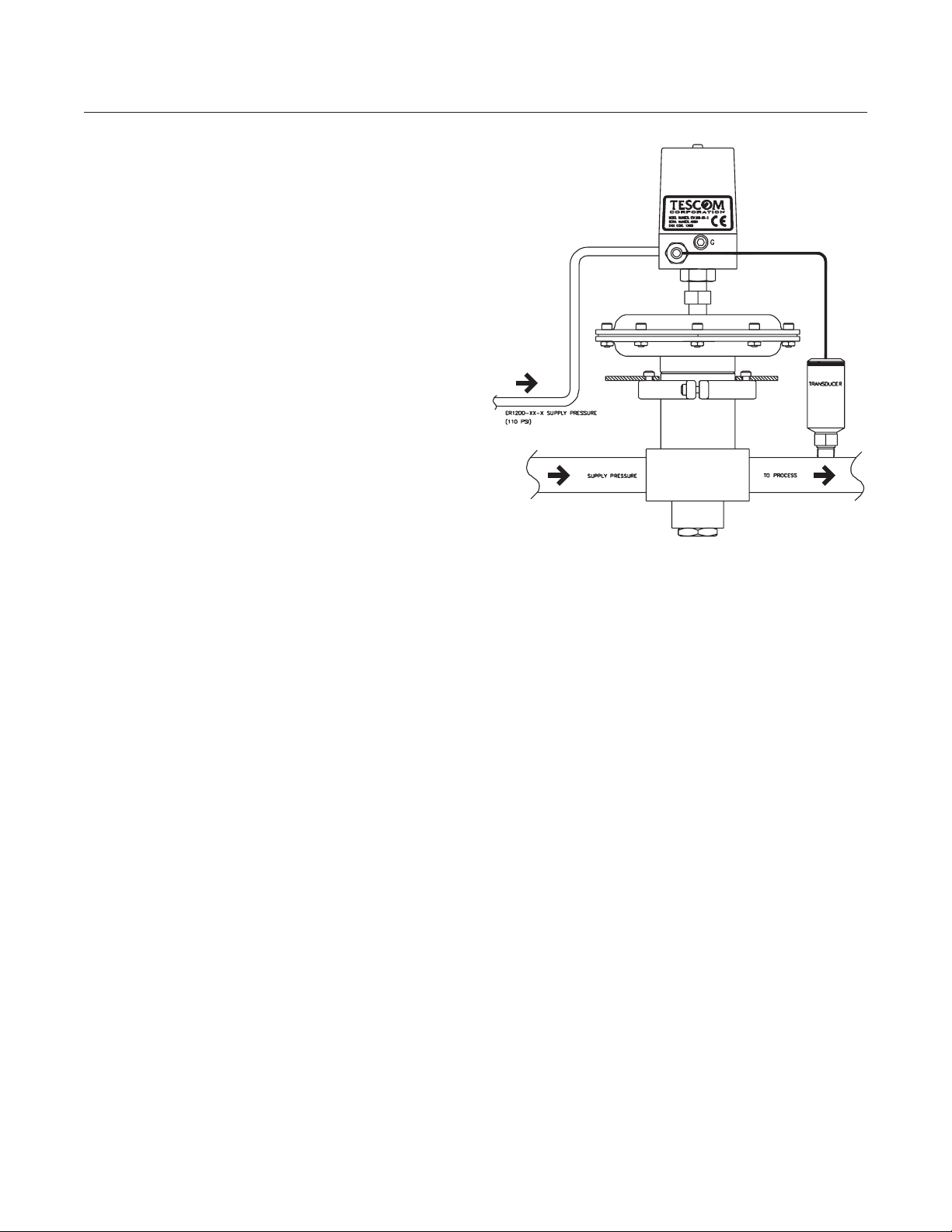
EXTERNAL FEEDBACK MODE
In External Feedback mode, the ER1200 can
be used to control flow, position, temperature,
or any other variable that can be affected by a
change in pressure. For the purpose of this
operation manual, we will discuss the control
of pressure. In this mode, the ER1200
compares an external feedback signal from a
customer supplied transducer to the setpoint.
Typically, this mode is used when the ER1200
is combined with either a pressure reducing or
back pressure regulator (shown with a ratio
actuated, pressure reducing regulator, Figure 2).
If the feedback signal is below setpoint, the
ER1200 opens its inlet valve and increases
output pressure. This increases pressure on
the dome of the regulator, opening the main
valve and increasing downstream pressure. If
the feedback is above setpoint, the ER1200
opens its exhaust valve, which decreases
dome pressure, allowing the regulator to
decrease output pressure.
Pressure Connections:
ER1200 inlet pressure is the same as in
internal mode. Refer to regulator installation
and operation instructions and the product
label for maximum inlet pressure information.
Figure 2
Page 4

SPECIFICATIONS
Enclosure
NEMA 4 housing
Mounting
2 10-32 UNF mounting holes
Power Requirement
24 Volts DC +/- 2 volts
150 milliAmp typical current draw
Input Signals
All signals are field configurable using
onboard jumpers:
Setpoint: 4-20 mAmp, 1-5 VDC or
0-10 VDC
Feedback: Internal (0-100 PSIG) or
external
External
Feedback: 4-20 mAmp, 1-5 VDC or
0-10 VDC
Inlet Pressure
Maximum: 120 PSIG
Typical: 110 PSIG
Minimum: 10 PSIG above desired
output pressure
Media
Clean, dry, inert gas
Environment
Temperature: -10°F to +150°F
Flow Stream Materials
300 Series SST, Buna-N, 6000 Series
Aluminum, Brass, Nickel, Silicon, Gold,
Glass, RTV
Performance
Total Accuracy: +/- 0.25%
Linearity: +/- 0.1%
Repeatability: +/- 0.12%
Flow Capacity: Cv= 0.03
3
Form # 1925 Rev. 4/06 TESCOM
1 White + Setpoint
2 Brown - Setpoint
3 Green + Feedback
4 Yellow + Analog Output
5 Black Power Ground
6 Red + TTL Output
7 Orange + 24 VDC Power
8 Violet* Secondary Ground
Wire Number Wire Color Function
ELECTRICAL INSTALLATION
*Not available for ER1200-2 and ER1200-2-1
Page 5

Form # 1925 Rev. 4/06 TESCOM
4
Current Setpoint - Active Source
Voltage Setpoint
Current Setpoint - Passive Source
Page 6

ER1200 CONFIGURATION
There are two printed circuit boards inside
the ER1200. The bigger, vertical board is
the control board. All the jumpers used to
configure the ER1200 are located on this
board. The tuning and calibration pots are
also located on the control board. (See
page 6 for details on tuning the ER1200.)
The smaller, horizontal board has two pots
used to zero and span the internal sensor.
These pots are set at the factory and should
NOT be adjusted.
CAUTION: CONFIRM POWER SUPPLY
IS OFF BEFORE MOVING JUMPERS.
CONFIGURE SETPOINT SIGNAL
MODE – JP1
• Current Setpoint Mode:
Install Jumper
• Voltage Setpoint Mode:
Remove Jumper
RANGE – JP2
• 4-20 mAmp/1-5 Volts:
Install Jumper on pins 1 & 2
• 0-10 Volts:
Install Jumper on pins 2 & 3
CONFIGURE ANALOG OUTPUT SIGNAL
MODE – JP6
• Current Output Mode:
Not available
• Voltage Output Mode:
Install Jumper on pins 2 & 3
RANGE – JP7
• 1-5 Volts:
Install Jumper on pins 1 & 2
• 0-10 Volts:
Install Jumper on pins 2 & 3
CONFIGURE FEEDBACK SIGNAL
MODE – JP5
• Current Feedback Mode:
Install Jumper
• Voltage Feedback Mode:
Remove Jumper
RANGE – JP4
• 0-10 Volts:
Install Jumper on pins 1 & 2
• 4-20 mAmp/1-5 Volts:
Install Jumper on pins 2 & 3
SOURCE – JP3
• Internal Feedback Mode:
Install Jumper on pins 1 & 2
• External Feedback Mode:
Install Jumper on pins 2 & 3
5
Form # 1925 Rev. 4/06 TESCOM
Figure 3
Page 7

TUNING THE ER1200
There are 5 adjustments located on the control
card. The initial factory pot settings are listed
in the following table.
CLOCKWISE
FUNCTION TURNS
Gain 11
Stability (Integral) 5
Deadband 7
Zero 18
Span 13
Note: The counter-clockwise end point from
which to start turning the pots is found by
rotating the pot counter-clockwise 25 turns.
• The easiest method for calibrating and
tuning the system is to use a volt meter to
monitor the setpoint and feedback voltages.
• Turn all the pots back to the factory settings.
• Apply a setpoint signal of at least 12.5%
(6 mAmps, 1.5 VDC if 1 - 5 VDC, or 1.25
VDC if 0 - 10 VDC).
• Rotate the Deadband pot until exhaust gas
can barely be felt escaping from the
exhaust port (see Figure 1, page 1) on the
base of the unit. Rotating the deadband pot
clockwise will decrease the deadband to the
point that the inlet and exhaust solenoid
valves will operate continuously. This will
result in a very accurate tracking response,
but obviously consumes gas. If the
deadband is increased by rotating the pot
counter-clockwise, pilot gas will be
conserved, but the system will not respond
to a change in setpoint or feedback until the
error signal is larger than the imposed
deadband voltage. This can result in drifting
of the feedback signal or no response to a
small change in setpoint signal.
• Apply a setpoint signal of about 2.5% (4.4
mAmps, 1.1 VDC if 1 - 5 VDC, or 0.25 VDC
if 0 - 10 VDC). Measure the feedback signal
and adjust the zero pot until the feedback
signal matches the setpoint signal. Rotating
the zero pot clockwise will increase the
feedback signal and a counter-clockwise
rotation will decrease the feedback signal.
Sufficient time should be given for the
system to respond between each
adjustment of the pots, especially if there is
a large control volume. Rotate the pots
slowly and observe the system reaction.
Zero Pot Rotation Effect
Figure 4: Zero Adjustment
• Apply a setpoint signal of about 95% (19.2
mAmps, 4.8 VDC if 1 - 5 VDC, or 9.5 VDC if
0 - 10 VDC). Measure the feedback signal
and adjust the span pot until the feedback
signal matches the setpoint signal. Again,
sufficient time should be given for the
system to respond between each
adjustment of the pots. Since the zero and
span adjustments interact with one another,
it is necessary to readjust the zero after
adjusting the span. Recheck the zero and
adjust it if the feedback signal does not
match the setpoint signal of 2.5%. Continue
to recheck zero and span until the feedback
signal and setpoint signal match at both the
low and high setpoint values.
6
Form # 1925 Rev. 4/06 TESCOM
Output
Signal (mA)
Page 8

TUNING THE ER1200 Continued
Span Pot Rotation Effect
Figure 5: Span Adjustment
Typically, Gain and Stability adjustments are
not needed. However, the following general
guidelines can be followed to fine tune your
system:
Rotating the gain pot clockwise increases the
system gain and decreases the system
response time. Too little gain will result in slow
response and inaccurate signal tracking. Too
much gain will result in system instability, fast
vibration, or in the feedback signal
overshooting the setpoint signal when a large
step change in setpoint is initiated.
Rotating the stability pot clockwise will
decrease the reset time and quicken the
addition of gain into the system. This can
again result in setpoint overshoot. Rotating
the pot counter-clockwise will increase the
reset time and dampen the control response
to a step change in setpoint.
The stability adjustment does not interact with
any of the other adjustments, however, if the
gain or deadband pots are turned at this point,
the zero and span will need to be readjusted
per the procedure outlined above.
Reaction To Step Change In Setpoint
Figure 6: System Response
If the system is experiencing a slow oscillation,
decrease the gain by rotating the pot counterclockwise until the oscillation stops. If the
oscillation is rapid, increase the reset action by
rotating the stability pot clockwise until the
oscillation stops. These settings will be the
maximum gain and minimum reset time that
can be used with the system as it is configured.
If the feedback signal severely overshoots the
setpoint signal when a change in setpoint is
made, turn the stability pot counter-clockwise
alternately with the gain pot (also counterclockwise), until the overshoot is eliminated.
For very precise tuning of the control, a dual
channel storage oscilloscope is recommended
so that the user can see the effect of gain and
integral adjustment on the response of the
system. One channel of the scope is used to
monitor the setpoint voltage and the other
channel to monitor the feedback voltage. The
gain and integral adjustments have the
greatest effect on the system response to a
step change in setpoint signal. The control
can be tuned in this fashion for millisecond
response to step changes in setpoint from 0 to
100%. Remember, after adjusting the gain
pot, the control will need to have its zero and
span readjusted.
7
Form # 1925 Rev. 4/06 TESCOM
Output
Signal (mA)
Under Damped
Critically
Damped
Over Damped
Feedback Response
0
Time
Page 9

TROUBLESHOOTING
ER1200 Symptom Cause Remedy
8
Form # 1925 Rev. 4/06 TESCOM
Unable to maintain outlet
pressure
Positive output pressure
with zero setpoint
Outlet pressure is equal
to inlet pressure
Outlet pressure does not
follow setpoint changes
Outlet pressure becomes
uncontrollable (unstable
or unable to establish
setpoint)
ER1200 exhaust valve
leaking
ER1200 supply pressure is
not high enough
ER1200 inlet solenoid valve
leaking
ER1200 supply pressure
exceeds the maximum
ER1200 not getting a
feedback signal
ER1200 jumpers not
configured correctly
ER1200 GAIN, INTEGRAL,
or DEADBAND are out of
adjustment
The feedback signal reacts to
a process change at a slower
bandwidth than the ER1200
(25 milliseconds)
There are leaks in the
downstream pressure line
The system design has
components that can cause a
delay in down stream
transducer response while
the up stream pressure is
allowed to build up (pressure
differential between
measurement point and
source)
Return unit to factory for
replacement of valve
Check the incoming pressure
to the ER1200 and ensure that
it is between 10 to 20 PSIG
above the maximum desired
output pressure
Return unit to factory for
replacement of valve
Lower supply pressure to less
than 115 PSIG
Check transducer wiring and
feedback jumper settings
Reconfigure jumper settings
according to page
Read TUNING THE ER1200
(page 6) in this manual and
readjust the gain and pots per
that section
Replace the transducer with
one that has a full range
response time at least as fast
as that of the ER1200
Locate and eliminate all leaks
Eliminate the flow restriction, or
slow down the ER1200
response time by restricting the
flow of supply pressure into the
ER1200
Page 10

Form # 1925 Rev. 4/06 TESCOM
Tescom
Industrial Controls
Systems Group
12616 Industrial Boulevard
Elk River, Minnesota 55330-2491
Toll Free 800-447-1250
Tel 763-241-3238
Fax 763-241-3224
e-mail: systems@tescom.com
www.TESCOM.com
 Loading...