

Tescan Vega 3 Sem Instructions For Use Manual

Scanning Electron Microscope
Instructions For Use

The reproduction, transmission or use of this document or its contents is not permitted without express written
authority.
Offenders are liable for damages. All rights reserved.
We have checked the contents of this manual for agreement with the hardware and software described. Since
deviations cannot be precluded entirely, we cannot guarantee full agreement.
© 2011 TESCAN, a.s., Brno, Czech Republic

Contents
3
VEGA 3 SEM
Contents
Contents ........................................................................................................................... 3
1 Introduction ................................................................................................................ 5
2 Safety Information ....................................................................................................... 6
3 Installation and Microscope Repairs ............................................................................. 7
3.1 Transport and Storage .............................................................................................. 7
3.2 Installation Instructions ............................................................................................ 7
3.3 Fuse Replacement ..................................................................................................... 7
3.4 Instrument Repair and the Spare Parts Usage ............................................................ 7
4 Description of the Microscope...................................................................................... 8
4.1 Electron Column ....................................................................................................... 8
4.1.1 Electron Column Displaying Modes .................................................................. 11
4.1.2 Electron Column Microscope Centering ............................................................ 16
4.2 Chamber and Sample Stage .................................................................................... 18
5 Vacuum Modes .......................................................................................................... 19
5.1 High Vacuum Mode ................................................................................................. 20
5.2 Medium Vacuum Mode ........................................................................................... 20
5.3 Low Vacuum Mode .................................................................................................. 21
6 Detectors .................................................................................................................. 22
6.1 SE Detector ............................................................................................................. 22
6.2 LVSTD Detector ....................................................................................................... 22
6.3 BSE Detector ........................................................................................................... 23
6.4 CL detector ............................................................................................................. 24
6.4.1 Exchange of CL for BSE lightguide .................................................................... 24
6.5 Other Detectors ...................................................................................................... 25
7 Control Elements ....................................................................................................... 26
7.1 Keyboard ................................................................................................................ 26
7.2 Mouse ..................................................................................................................... 26
7.3 Trackball ................................................................................................................. 27
7.4 Control Panel .......................................................................................................... 27
8 Getting Started .......................................................................................................... 28
8.1 Starting the Microscope .......................................................................................... 28
8.2 Specimen Exchange ................................................................................................ 28
8.3 Images at Low Magnification ................................................................................... 29
8.4 Imaging of non-conductive samples without coating.............................................. 33
8.5 Images at High Magnification .................................................................................. 35
8.6 Stopping the Microscope ........................................................................................ 37

Contents
4
VEGA 3 SEM
9 Microscope Maintenance ............................................................................................ 38
9.1 Basic Microscope Accessories ................................................................................. 38
9.2 Filament Exchange .................................................................................................. 39
9.3 Starting up the Microscope after a Filament Exchange ............................................ 42
9.4 Mechanical Gun Centering ...................................................................................... 44
9.5 Aperture Exchange ................................................................................................. 44
9.5.1 Exchange of the Aperture Holder...................................................................... 45
9.5.2 Insertion of the Low Vacuum Aperture Holder .................................................. 45
9.6 Cleaning the Column .............................................................................................. 46
9.6.1 Types of Contamination or Impurities .............................................................. 46
9.6.2 Cleaning the Column Parts ............................................................................... 47
9.6.3 The Frequency of Cleaning ............................................................................... 49
9.7 Specimen Holders ................................................................................................... 49

Introduction
5
VEGA 3 SEM
1 Introduction
The VEGA 3 series is a family of modern, fully PC-controlled scanning electron microscopes
with a tungsten heated filament.
Specific Features of the VEGA 3 SEM:
An innovative and powerful four lens Wide Field Optics™ design, offering a variety
of working and displaying modes.
A range of chambers to suit all applications and a wide choice of supplementary
accessories.
Fast and precise motorized specimen stages.
Excellent analytical qualities with optimized ports geometry.
Unique live stereoscopic imaging using the 3D Beam technology.
Turbomolecular and rotary pumps ensure quick and easy sample exchange and short
times to reach a working vacuum.
Sophisticated and easy-to-use software for microscope control using a Windows™
platform.
Fully automated microscope set-up.
Comprehensive software for image archiving, processing, evaluation and network
operations comes as standard.
Minimal requirements on space, power supply and environment.
Currently the VEGA 3 family includes several models of microscope fitted with various
chambers according to the user’s requirements for chamber size, stage movements
precision and/or operation comfort. The abundant control software included in the standard
scope of delivery is one of the valued assets of the Vega microscopes.
Since the VEGA 3 SEM is installed and maintained by trained specialists, technical details and
installation procedures are limited to a short overview. In the case of necessary maintenance,
reinstallation, hardware changes, etc. the appropriate service authorities or your local
supplier have to be contacted for further assistance and instructions.

Safety Information
6
VEGA 3 SEM
2 Safety Information
The user is liable to make himself familiar with the care of the device and with the safety
rules valid in the country of the user. The microscope works with electric voltages that can
be dangerous to life.
Any operations with the device which are not mentioned in these instructions, especially the
removal of the housing and manipulation of the electric parts of the microscope, may be
carried out only by an authorized person. It is also forbidden to substitute a part of the
microscope for any other part that is not original and is not delivered by the microscope
producer (e.g. the substitution of the original steel blinds on the flanges of the microscope
chamber for light alloy blinds can cause an emission of dangerous ionizing radiation!)
The microscope is provided with a number of automatic protections making unsuitable
usage impossible (e.g. it is not possible to switch on high voltage sources if the specimen
chamber or electron gun space are open or are not evacuated to the working vacuum). The
deactivation of these protections can cause destruction of the machine and endanger the
health of the operating staff. It is strictly forbidden.
The symbols used meet the regulation standard ČSN EN 61010-1, except the symbol:
that marks the connectors with high voltage which are not dangerous in the aspect of the
mentioned regulation standard (accidental touch can only cause electrical shock).
In the documentation there are two types of additional information given: Notes and
Warnings,
Notes are designated thus:
Note:
In Italics and Blue print.
Warnings are designated thus:
WARNING:
In Italics and Red print.

Installation and Microscope Repairs
7
VEGA 3 SEM
3 Installation and Microscope Repairs
3.1 Transport and Storage
The method of delivery is defined in the contract and is determined individually according
to the destination territory. The method of delivery must be approved by the manufacturer.
The instrument is delivered partially disassembled and packed. The purchaser is obliged
to check the status of the boxes after the delivery company handover. In the case of any
damage it is necessary to catalogue the damage and inform the manufacturer of the
situation. The packed instrument must be stored in a dry and clean place with a temperature
range from -20°C to +40°C and must not be exposed to corrosive substances which can
cause oxidation (acid vapours etc.).
3.2 Installation Instructions
The microscope is delivered including installation. The installation must be ordered from the
seller. The customer shall inform the seller of the readiness of the laboratory for the
installation. Once the laboratory is ready, technicians of the manufacturer or technicians
of an approved company will carry out the installation, connection to the mains and user
training. The customer is not allowed to connect the microscope to the mains or do any
other manipulation, except moving the microscope to the storage place. The installation
company will fill in the installation protocol. The warranty period will start from this date and
the user can start using the instrument normally as described in this manual.
3.3 Fuse Replacement
The instrument does not contain any fuses which can be replaced by the user. All fuses are
located under the covers which can be removed only by the service technician from the
manufacturer or the service technician of an approved company. The fuses can be replaced
only by exactly the same type; the type is described in the documentation or on the fuse
holder.
3.4 Instrument Repair and the Spare Parts Usage
It is only permitted to use original spare parts delivered by the manufacturer. Repair and
maintenance which exceed the procedures mentioned in this manual can be performed only
by the manufacturer’s service technician or a service technician from an approved company.

Description of the Microscope
8
VEGA 3 SEM
4 Description of the Microscope
4.1 Electron Column
The scanning electron microscope displays the examined object by means of a thin electron
probe. The column forms the electron probe (beam) and sweeps the beam over the
examined specimen located in the microscope chamber. The imaging qualities of the
microscope depend on the parameters of this electron beam:
spot size, aperture angle
and
beam intensity
.
The spot size determines the resolution of the microscope as well as usable magnification
at stable picture sharpness. It is mainly considered that the spot is circular and has
a Gaussian intensity profile. We can specify its size for example with half the width of the
intensity distribution. The spot size is determined by the demagnification of the primary
electron source, optical aberrations of the final lens (objective) and the diffraction aberration
on the final aperture. The spot size is smaller at shorter working distances.
The incident electron beam is cone-shaped. The vertex angle of the cone is called the
aperture angle. The wider the cone, the lower the depth of focus.
The beam intensity (BI) is the number of electrons passing through the probe in a defined
time. The image noise of the electron microscope depends on the number of electrons used
for the information collected from each picture element. It is necessary to use more time for
image scanning at low beam intensity and vice versa.
It is evident that the incident beam parameters influence each other. The optical system
of the microscope allows operation in different modes when some parameters of the beam
can be preferred and the others can be kept down. Here are some typical examples:
Work on high magnification
. It is necessary to reach a high resolution, therefore low
beam intensity, short working distance and slow scanning speed should be used. We
recommend choosing RESOLUTION mode, working distance not more then 7 mm and
scanning speed 7 or slower. See chapter 4.1.1.
Work with high intensity.
The spot size and the aperture angle are big; resolution is
small. Useful magnification is low but fast scanning can be used because the signal
to noise ratio is better. The higher the BI index, the higher the intensity.
Work with high depth of focus
. The aperture angle must be small. Use Depth mode.
Description of the Microscope
9
VEGA 3 SEM
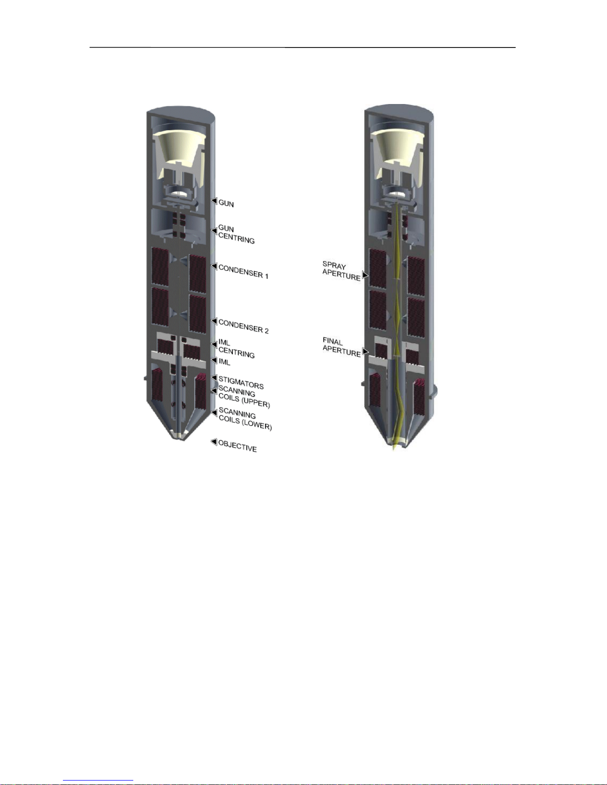
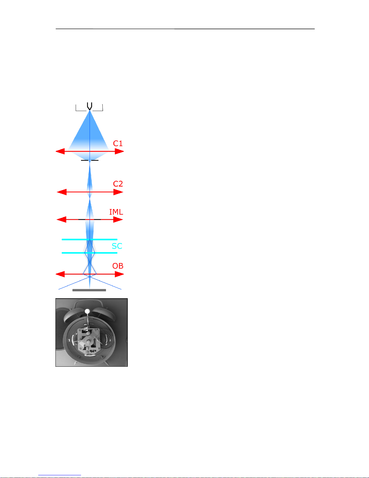
The VEGA 3 SEM cross section and schematic representation of the optical elements
The column of the microscope consists of the following main parts:
The electron gun is a source of accelerated electrons. It consists of a cathode,
Wehnelt cylinder and anode. The cathode and Wehnelt cylinder are connected to the
negative electric potential; the anode and the remaining part of the column are
on the earth potential. The cathode is a tungsten filament, heated to such a high
temperature that it causes emission of free electrons. The voltage between the
Wehnelt cylinder and the anode determinates the
accelerating voltage
of electrons
and thus their energy. The electron flow from the gun is specified with the
emission
current
. The emission current can be changed by applying negative potential between
the Wehnelt cylinder and the cathode (
bias
). The whole gun system works as a “virtual
source” of electrons with the following specifications: the dimension 25 – 50 µm, the
electrons energy from 200 eV up to 30 keV, the emission current up to 300 µA and
its brightness 106 A/cm2sr.
The gun centering is formed by a system of electromagnetic deflection coils under
the gun. It is designed for the tilting of the electron beam emitted from the gun
so that it enters the axis of the optical system of the column. It is controlled by the

Description of the Microscope
10
VEGA 3 SEM
function gun alignment. The gun is correctly centered if the most intensive part
of the electron beam is selected and the brightness of the image is the highest.
The spray aperture is placed under the centering coils of the gun. It is intended for
retaining the marginal parts of the electron beam emitted by the gun.
The pair of condensers C1 and C2 are strong magnetic lenses for the demagnification
of the virtual source. The higher the excitation of the condenser, the shorter its focal
length and the higher its demagnification.
The final aperture cuts the size of the final incident beam. It is placed in the holder
at the end of the central vacuum pipe of the column, about 60 mm under condenser
C2. The optimum size of the aperture hole is 50 µm.
The auxiliary lens IML is a magnetic lens used for the aperture change of the beam
entering the lens OBJ or for displaying if the OBJ is off. The change of the IML
excitation causes the shifting of the electron beam across the optical axis and
therefore it is necessary to compensate this shifting by means of the centering coils
IML Centering.
The Stigmator is an electromagnetic octupole. It is intended to compensate for
astigmatism in all displaying modes.
The scanning coils are formed by two stages of the deflection coils. A scanning ramp
is connected to the coils. The ramp frequency determines the scanning speed of the
electron beam; the amplitude determines the microscope's field of view and the
magnification.
Objective OBJ is the last magnetic lens of the column that forms the resulting
electron beam. In the usual modes the excitation of the OBJ is determined by the
working distance - the distance between the lower objective pole piece and the
focused specimen surface.
Description of the Microscope
11
VEGA 3 SEM
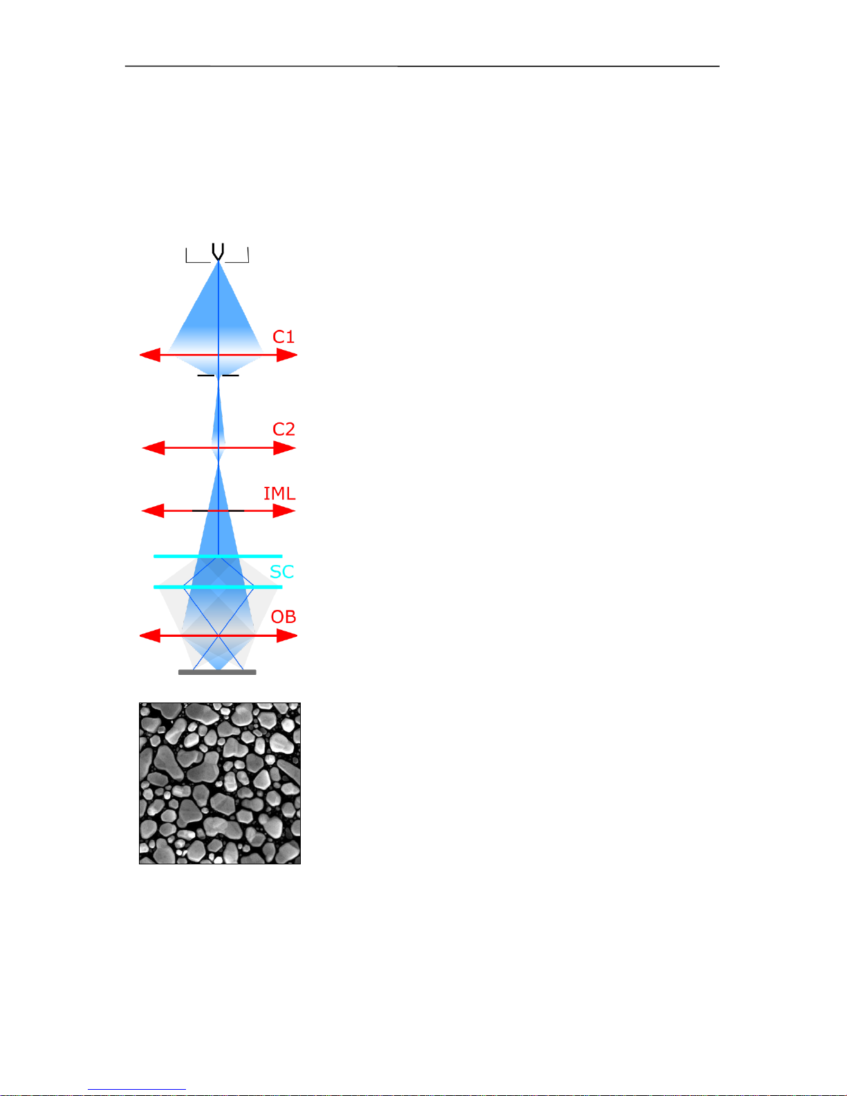
4.1.1 Electron Column Displaying Modes
RESOLUTION Mode
This is the basic and most common displaying mode. The IML lens is switched off, the OBJ
lens is excited and it focuses the final electron beam.
Characteristics:
high resolution
low depth of focus
In this mode, the VEGA 3 works like other common three lens
microscopes without IML lens. The aperture is nearly optimal for
lower BI values (small spot size, low beam current), short
working distances (4 - 5 mm) and for the accelerating voltage
30 kV. The pivot point of the scanning and the electric image
shifts are close to the principal plane of the objective OBJ,
so that the curvature of the field, distortion and field of view are
as good as possible. The centering of the objective OBJ is
performed by defined beam tilt of the central electron beam,
which does not cause image shift. This mode is intended for
displaying with the highest resolution.
Description of the Microscope
12
VEGA 3 SEM
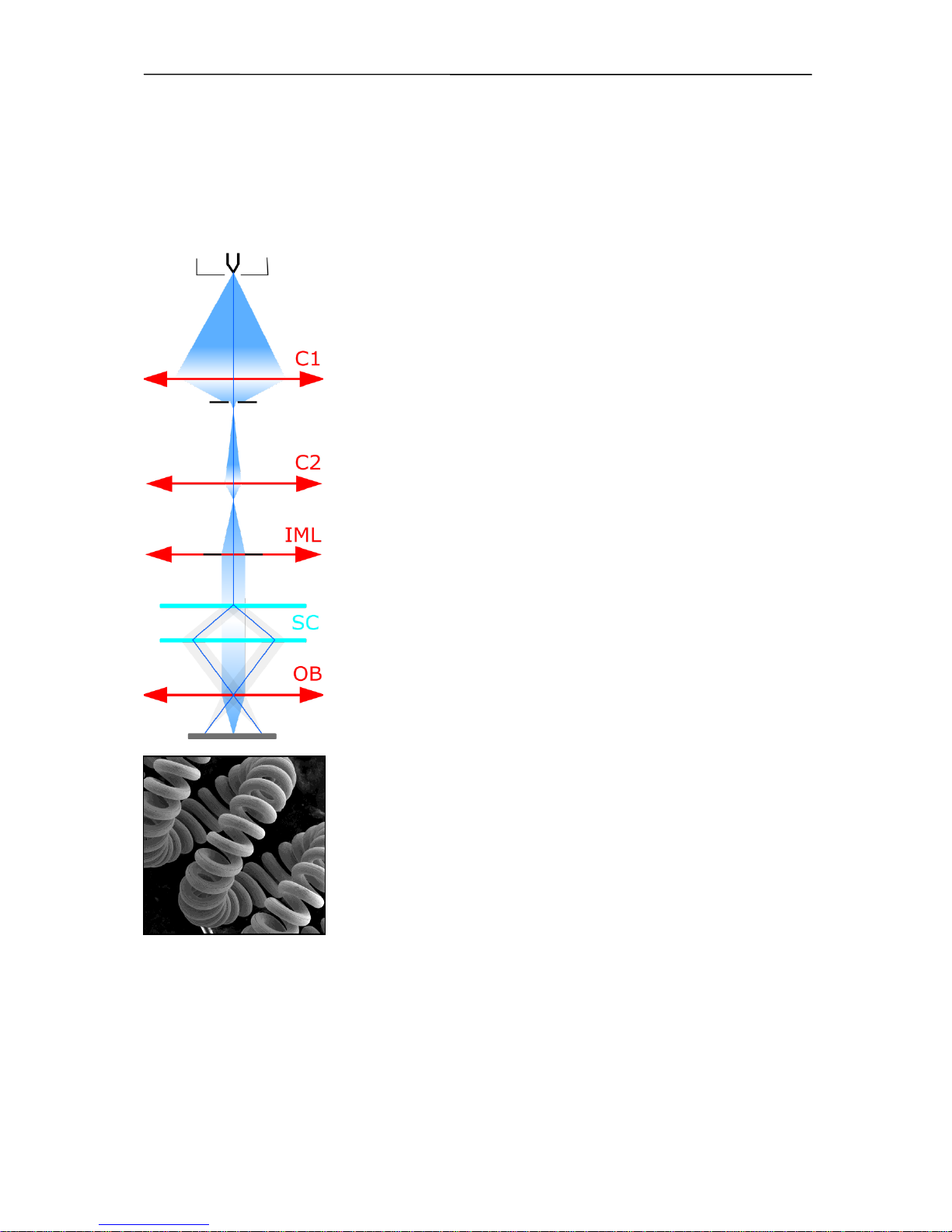
DEPTH Mode
The DEPTH mode differs from the previous mode by the auxiliary lens IML being switched
on.
Characteristics:
good resolution
increased depth of focus
The aperture of the final beam is lower, but the spot size is
bigger in comparison with the RESOLUTION mode. The beam
in the probe stays unchanged. This mode is used if it is necessary
to have a greater depth of focus.
Description of the Microscope
13
VEGA 3 SEM
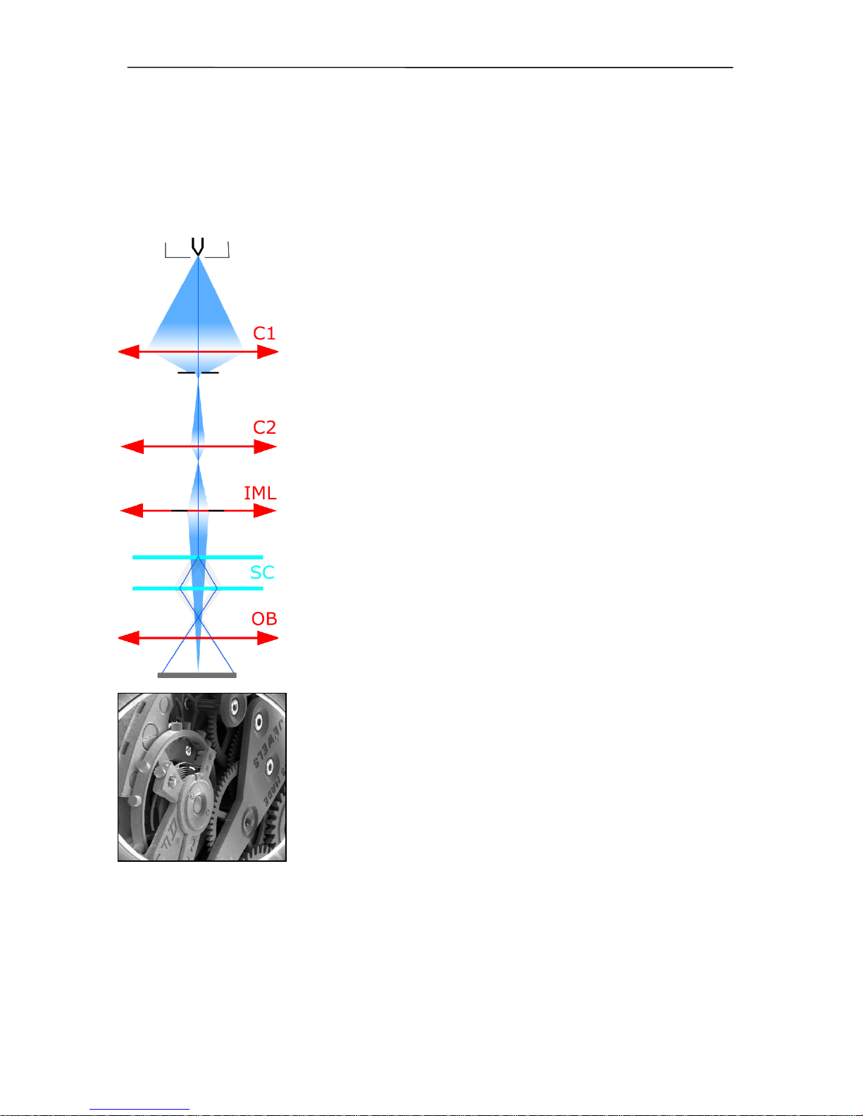
FIELD Mode
The FIELD mode utilizes the intermediate lens IML for the electron beam focusing while the
objective OBJ is off.
Characteristics:
large field of view
high depth of focus
worse resolution
The beam aperture is very small and the depth of focus is usually
higher than the field of view. As the objective OBJ is off in this case,
it does not affect the middle beam and thus does not need to pass
near the centre of the objective OBJ. The position of the pivot point
of scanning is optimized according to the field of view. The
centering coils IML center the supplemental intermediate lens IML
to avoid image movement during focusing. The DC component
of the scanning coils is set up so that no image shift occurs
if switched from the RESOLUTION mode to the FIELD mode.
The characteristic of this mode is a bigger spot size. The maximum
magnification used is therefore a few thousand. The mode is used
for the searching of the parts of the specimen to be examined.
Description of the Microscope
14
VEGA 3 SEM
WIDE FIELD Mode
The WIDE FIELD mode uses the intermediate lens IML for focusing the electron beam, while
the objective OBJ is excited to a high value.
Characteristics:
extra large field of view
image distortion is corrected and minimized
only available for post-2007 devices
Highly excited objective multiplies the deflection of the beam. The
aperture of the beam is very small and the depth of focus is very
high. The IML Centering coil serves for minimizing the image shift
when focusing.
The mode is used to search for the part of the specimen to be
examined. To know the proper magnification value, the objective
must be well focused. This might be a little difficult due to the
high depth of focus.
Description of the Microscope
15
VEGA 3 SEM
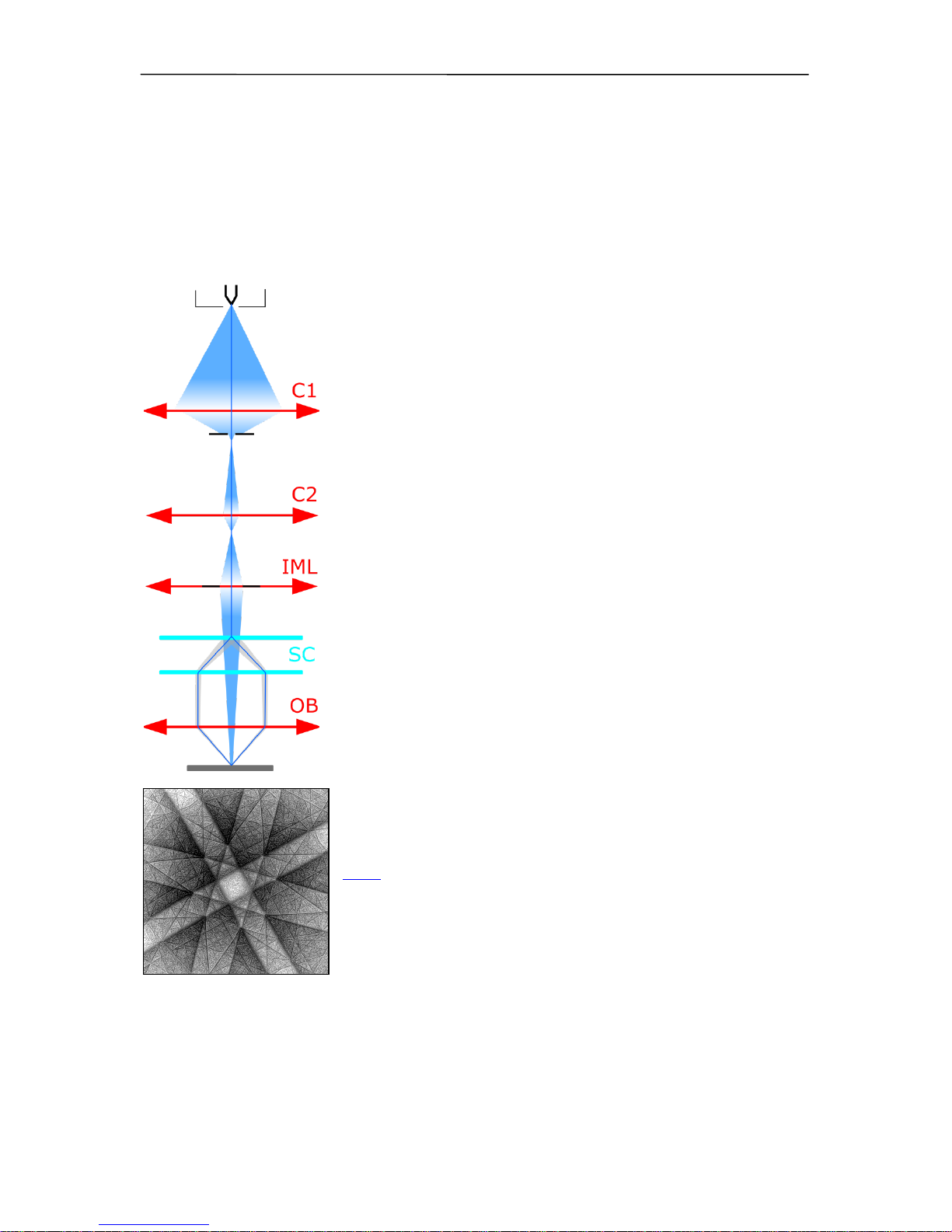
CHANNELING Mode
In the CHANNELING mode, the scanning and lens focusing is controlled so that the electron
beam touches the same point of the specimen surface all the time. By means of scanning the
beam, only the angle of incidence of the electron beam is changed, i.e. the rocking beam.
Characteristics:
the position of the specified point in the image depends
on the beam tilt
it is the mode for ECP acquisition - Electron Channeling
Pattern
The resulting image is the amount of electrons dependent on the
impacting beam angle. The excitation ratio of the scanning coils
is set up so that the beam utilizes the whole area of the objective
lens bore and enters the lens parallel to the optical axis.
All electron beams parallel to the optic axis are focused by the
lens into a single point on the specimen surface. As a consequence, the scanning is transformed into beam tilting, i.e. the
resulting pivot point of the scanning lies on the specimen
surface plane.
The intermediate lens focuses the beam into the upper focal
point of the objective lens. The result is that the beam, after
passing through the objective lens, is parallel and the angular
resolution of ECP (Electron Channeling Pattern) images is at its
maximum.
The mode is intended for the examination of crystallographic
materials. The minimum size of crystals should be 150 µm.
Note: ECP patterns are produced by back scattered electrons, it
is preferable to use a BSE detector for imaging if available.
 Loading...