

TES TES-3600 Instruction Manual
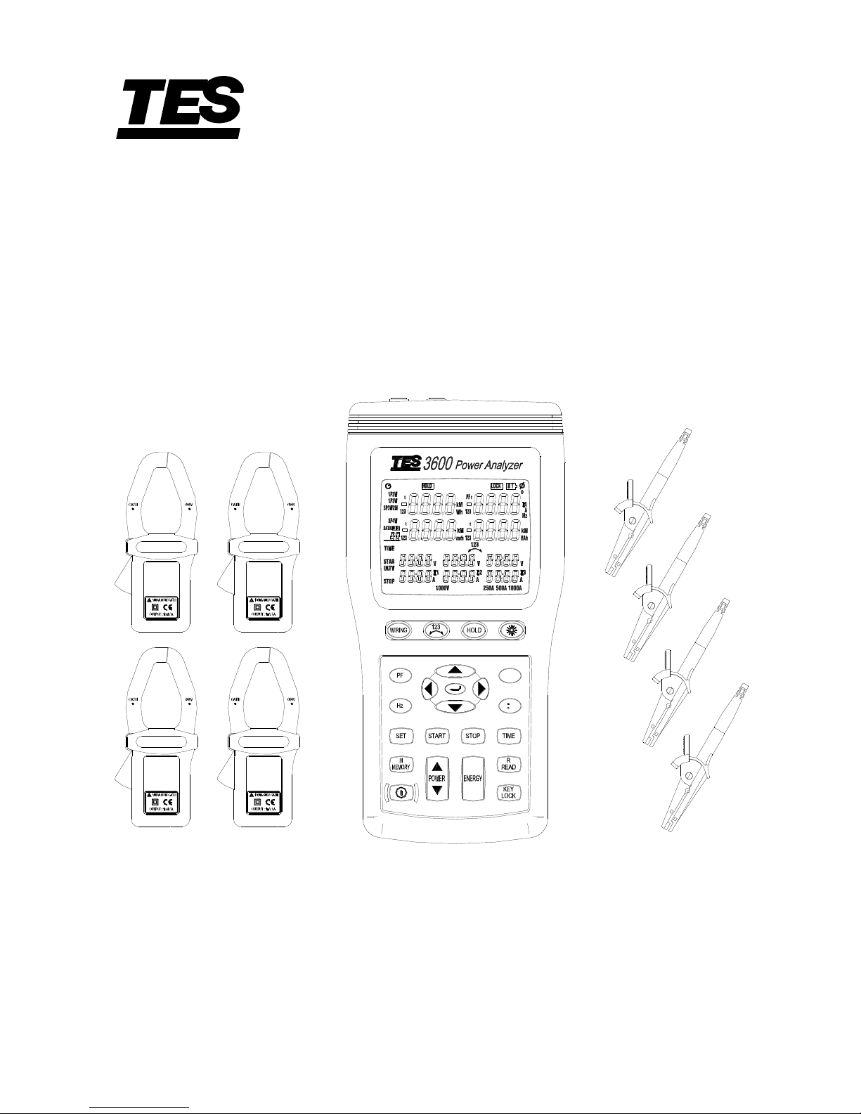
3P4W POWER ANALYZER
TES - 3600
INSTRUCTION MANUAL
3 4
1 2
I4
U3 m-sU12 Y-M U23 D-h
£c
NO.
Q
P
S
TES ELECTRICAL ELECTRONIC CORP.
Shop for Data Logging products online at: www.DataLoggerStore.ca 1.877.766.5412

CONTENTS
Title Page
I. SAFETY INFORMATION ........................................................................................... 1
II. INTRODUCTION FEATURE ..................................................................................... 4
III. SPECIFICATIONS ........................................................................................................ 4
3-1 Environment Conditions ....................................................................................... 4
3-2 Safety Specifications ............................................................................................. 5
3-3 General Specification ............................................................................................ 5
3-4 Electrical Specification ......................................................................................... 7
IV. PARTS & CONTROLS ............................................................................................... 10
4-1 Description of Parts & Control keys ................................................................... 10
4-2 Description of Display ........................................................................................ 12
V. OPERATING INSTRUCTION ................................................................................. 15
5-1 AC Current Adaptor ............................................................................................ 15
5-2 Single-Phase 2-Wire (1P2W) Power System Measurement ............................... 17
5-3 Single-Phase 3-Wire (1P3W) Power System Measurement ............................... 20
5-4 Three-Phase 3-Wire (3P3W) Power System Measurement ................................ 23
5-5 Three-Phase 4-Wire (3P4W) Power System Measurement ................................ 26
5-6 Only One Current I4 Measurement ..................................................................... 29
5-7 Manual Data Memory and Read Function Operation ......................................... 29
5-8 Auto Datalogging Function Operation ................................................................ 30
5-9 Phase Sequence Measurement ............................................................................ 31
5-10 Voltage, Current Waveform and Harmonic Analyzer ........................................ 31
5-11 Disable Auto Power Off Function ..................................................................... 31
VI. MAINTENANCE ......................................................................................................... 32
6-1 General Maintenance .......................................................................................... 32
6-2 Battery Replacement ........................................................................................... 32
VII. RS-232 INTERFACE, SOFTWARE INSTALLATION AND OPERATION.... 33
Shop for Data Logging products online at: www.DataLoggerStore.ca 1.877.766.5412

I. SAFETY INFORMATION
This Instruction Manual provides information and warnings essential for operating
this meter in a safe manner and for maintaining it in safe operating condition. Before
using this meter, be sure to carefully read the following safety information.
DANGER
During high voltage measurement, incorrect measurement procedures could
result in injury or death, as well as damage to the meter. Please read this
manual carefully and be sure that you understand its contents before using the
meter.
DANGER
Do not use the meter or test leads if they look damaged.
Use extreme caution when working around bare conductors or bus bars,
Accidental contact with the conductor could result in electric shock.
To avoid damages to the meter, do not exceed the maximum limits of the input
values shown in the specifications.
Use the meter only as specified in this manual, otherwise, the protection
provided by the meter may be impaired.
SAFETY SYMBOLS
Caution refer to this manual before using the meter.
This symbol is affixed to the meter where the operator should consult
corresponding topics before using relevant functions of the meter.
This mark indicates explanation, which is particularly important that the
user should read before using the meter.
Dangerous voltages.
Meter is protected throughout by double insulation or reinforced insulation.
When servicing, use only specified replacement parts.
Comply with IEC61010-1, 2nd edition
Shop for Data Logging products online at: www.DataLoggerStore.ca 1.877.766.5412
2
DANGER : Indicates that incorrect operation presents extreme danger of
accident resulting in death or serious injury to the user.
WARNING : Indicates that incorrect operation presents significant danger of
accident resulting in death or serious injury to the user.
CAUTION : Indicates that incorrect operation presents possibility of injury to
the user or damage to the meter.
NOTE : Denotes items of advice related to performance of the meter or to its
correct operation.
NOTES ON USE
In order to ensure safe operation and to obtain maximum performance from the
meter, observe the caution listed below.
Installation
CAUTION
The meter is designed for indoor use and can be safely used at temperatures
ranging from 0℃ to 40℃.
Do not store or use the meter where it will be exposed to direct sunlight, high
temperature, high humidity, or condensation, if exposed to such conditions, the
meter may be damaged, the insulation may deteriorate, and the meter may no
longer satisfy its specifications.
The meter does not construct to be waterproof or dustproof, so do not use it in
a very dusty environment or in one where will get wet.
Do not use the unit where it may be exposed to corrosive or explosive gas. The
meter may be damaged, or may occur explosion.
Before use
WARNING
To prevent electric shock, do not allow the meter to become wet and do not use
the unit when your hands are wet.
When working with live circuits, take all suitable precautions against
accidents, including the use of electrical safety gear such as rubber gloves,
rubber boots, and safety helmets.
Shop for Data Logging products online at: www.DataLoggerStore.ca 1.877.766.5412
3
Connecting meter
WARNING
To prevent electric shock, turn the power off before connecting the test leads
and then take measurements.
In order to prevent electrical shock and short – circuit accidents, shut off the
power to the line to be measured before connecting the line to be measured to
the voltage input terminals.
CAUTION
The measurement input and synchronizing input are not isolated from each
other. Connecting either one means that the other is exposed it is live, and
there is a danger of electric shock. To avoid electrical shock, connect both
terminals.
WARNING
To avoid electrical shock and / or meter damage, use caution when connecting
test leads to live components. The jaws of alligator clips can create a short
circuit between closely spaced live parts. Avoid making connections to feeder
conductors or bus bars at elevated potentials. Whenever, please make
connections to the output side of a circuit breaker as possible as you can, which
can provide better short circuit protection.
Follow all legal requirements.
Follow all instructions in the manuals.
Obey posted instructions.
Never assume that a circuit is de-energized, check it first.
Always set up the measurement first, then connect the test leads to the circuit.
Remove all test leads that are not in use.
Make connections to the meter first, before connecting leads to a live circuit.
Connect the ground lead first, then the voltage leads and the current probe,
Disconnect in reverse order.
Route test leads carefully.
Shop for Data Logging products online at: www.DataLoggerStore.ca 1.877.766.5412

4
II. INTRODUCTION FEATURE
The symptoms of poor power quality include intermittent lock-ups and resets,
corrupted data, premature equipment failure, over-heating of components for no
apparent cause, etc. The ultimate cost is in downtime, decreased productivity and
frustrated personnel.
Use power analyzer to power quality trouble shooting can help you keep your
power system up and running, troubleshoot problems quickly, improve power
efficient, manage energy costs, zero in on harmonics, optimize power system
performance, improve power quality and analyze system data to design optimal
upgrades.
10 display Easy-to-view LCD screen, and is capable of showing many power
quality parameters at the same time.
4 current probe including for measuring a neutral line current.
Measures single-phase 2-wire, single-phase 3-wire, three-phase 3-wire and
three-phase 4-wire systems.
All True-RMS sensing , V, A, KW, KVAR, KVA, PF, θ, Hz, KWh, KVARh and
KVAh measurements.
Phase sequence indicator function.
Backlight display function.
Manual Data Memory and Read (99 sets).
Data logging (504K byte memory, 12,000 sets per block, total 20,000 sets).
RS-232 optical interface with three phase voltage / current waveform display and
harmonic analysis.
Easy-to-use key operation.
Light weight and portable design.
III. SPECIFICATIONS
3-1 Environment Conditions:
Altitude up to 2000 meters
Indoor use only
Relatively humidity 80% max.
Operation ambient 0~40℃
Shop for Data Logging products online at: www.DataLoggerStore.ca 1.877.766.5412

5
3-2 Safety Specifications
Category Rating : 1000V Measurement Category III, Pollution Degree 2.
: IEC 61010-1 2nd Edition
CAT III : Measurement category in which measurements performed in the
building installation.
Safety Characteristics :
Current Clamps, Model TES AC3600, to be used only with the Three-Phase
Power Analyzer, Model TES-3600.
This manual contains information and warning that must be followed by the user
to ensure safe operation and to keep the meter and its accessories in a safe
condition.
Use of this meter and its accessories in a manner not specified by the
manufacturer may impair the protection provided by the equipment.
Equipment operation, the responsible body shall be made aware that, if the
equipment is used in a manner not specified by the manufacturer, the protection
provided by the probe assembly may be impaired.
3-3 General Specification
Maximum voltage between voltage input terminals and earth ground :
1000 Vrms
Maximum rated working voltage for current input : 0.35 Vrms
Maximum current for current probe : 1000 Arms
Numerical 10 display : 10 display 4 digit LCD maximum reading 9999.
Battery life : approx. 50 hours.
Auto power off : approx. 30 minutes.
Low battery indication : The
BT
is displayed when the battery voltage drops
below the operating voltage.
Backlight display time : Auto off approx. 30 seconds.
Sampling rate : Approx. 1 time per 2 seconds (Digital display).
Waveform and harmonic analyzer : 64 samples per period.
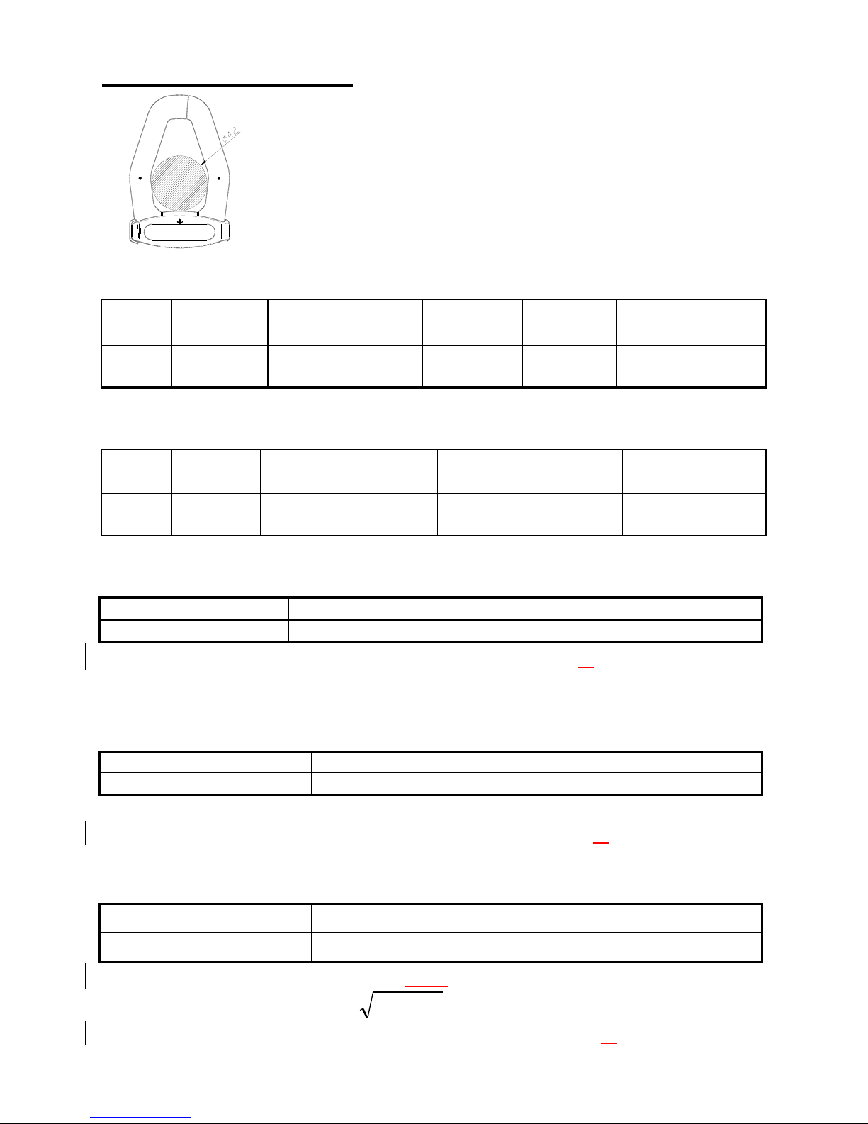
Current probe jaw opening diameter : Cables ψ40mm.
Operating temperature : 0℃ to 40℃
Operating humidity : Maximum relative humidity of 80% for temperatures up to
31℃ decrease linearly to 50% relative humidity at
40℃ (non-condensed).
Temperature coefficient : 0.1 (specified accuracy)/℃ (<18 or >28℃)
Shop for Data Logging products online at: www.DataLoggerStore.ca 1.877.766.5412
6
Storage temperature and humidity : -10℃ to 60℃
R.H. < 70% non-condensed.
Dimensions : Meter → 235(L)117(W)54(H)mm.
Current probe → 193(L)88(W)40(H)mm.
Weight : Meter including battery → approx. 730g
Current probe → approx. 333g
Accessories :
1. TES 3600 AC CURRENT ADAPTOR x 4pcs
Category Rating : CAT III 600V per IEC61010-1, Pollution Degree2.
: IEC 61010-1 2nd Edition and IEC61010-2-032
Input : AC 1000A maximum.
Output : 0.35mV/A
2. Voltage test lead x 4pcs
Model no : TL 202I
Manufacturer : Hong Kai Co., Ltd.
Category Rating : CAT III, 1000V, AC 10A Max.
3. Alligator clip x 4pcs
Model no : FC-A23
Manufacturer : Fu Chyi Enterprise CO., Ltd.
Category Rating : CAT III, 1000V, AC 10A Max.
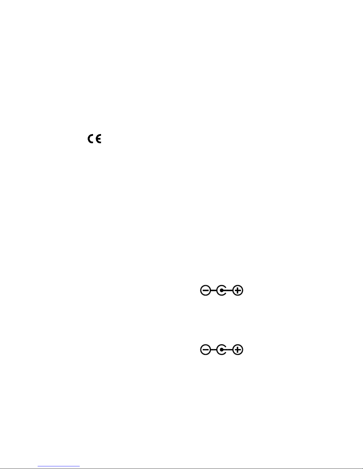
4. AC Adaptor (IN-OUT Isolated type, Input 120V AC 60Hz
Model : MW35-1200300
Input : 120V AC 60Hz 6.1W
Output : 12V DC 300mA
Manufacturer : MAW WOEI Enterprise CO., Ltd.
AC Adaptor (IN-OUT Isolated type, Input 230V AC 50Hz
Model : MWD48-1200300GS
Input : 230V AC 50Hz
Output : 12V DC 300mA
Manufacturer : MAW WOEI Enterprise CO., Ltd.
5. Battery 1.5V “AA” 8
6. Instruction manual 1
7. PC software CD-R 1
8. Carrying case 1
9. Optical RS232 interface 1
Shop for Data Logging products online at: www.DataLoggerStore.ca 1.877.766.5412
7
3-4 Electrical Specification
Accuracy : ±(% of reading + number of digits) at 18℃ to
28℃ ( 64℉ to 82℉ ) with relative humidity to 80%.
The current error is specified within the largest circle which
can be drawn inside the jaw.
AC Voltage Trms measurement (V) :
Range
Resolution
Accuracy
Input
impedance
Overload
protection
Nominal power
system frequency
999.9V 0.1V
(0.3%rdg10dgts)
(>50V)
2M
Ω
1000Vrms
Only 50Hz or 60Hz
Display item : RMS voltage value for each channel.
AC Current Trms Measurement (A) :
Range
Resolution
Accuracy
(including current probe)
Current
probe output
Overload
protection
Nominal power
system frequency
999.9A
0.1A
(0.5%rdg15dgts)
(>3A)
0.35mV/A
1000Arms
Only 50Hz or 60Hz
Display item : RMS current value for each channel.
Active Power measurement P (KW) :
Range
Resolution
Accuracy
999.9KW
0.1KW
1.0%rdg20dgts
Display items : Active power of each channel and its sum of multiple channels.
Polarity display : For influx (consumption) No symbol, For outflow
(regenerative) “ - ”.
Apparent Power measurement S (KVA) :
Range
Resolution
Accuracy
999.9KVA
0.1KVA
1.0%rdg20dgts
Measurement method : Calculate from RMS voltage U and RMS current I.
Display item : Apparent power of each channel and its sum of multiple channels.
Polarity display : No polarity.
Reactive Power measurement Q (KVAR) :
Range
Resolution
Accuracy
999.9KVAR
0.1KVAR
1.0%rdg20dgts
Measurement method : Calculate from apparent power S and active power P,
Q=
S P
2 2
.
Display item : Reactive power of each channel and its sum of multiple channels.
Shop for Data Logging products online at: www.DataLoggerStore.ca 1.877.766.5412

8
Polarity display : For phase lag (LAG : current is slower than voltage) :
No symbol.
For lead phase (LEAD : current is faster than voltage) : “-”
Power Factor measurement (COSψ) :
Range
Resolution
Calculated Accuracy
0 ~ +1
0.001
3dgt
Measurement method : Calculate from apparent power S and active power P,
PF = COSψ=
P S/
Display item : Power factor of each channel and its sum of multiple channels.
Phase angle measurement (ψ) :
Range
Resolution
Calculated Accuracy
+90°~ 0°~ -90°
0.1°
3dgt
Measurement method : Calculate from power factor COSψ,ψ= COS-1PF.
Display item : Phase angle of each channel and its sum of multiple channels.
Polarity display : For phase lag (LAG : current is slower than voltage) :
No symbol.
For phase lead (LEAD : current is faster than voltage) : “-”.
Frequency measurement (Hz) :
Range
Resolution
Accuracy
Measurement source
60HZ
0.1Hz
0.1%rdg2dgt
Voltage U1 > 50V
Measurable input range : > 50V
Three Phase Sequence Detection :
Input voltage range
Normal phase indication
Reverse phase indication
Measurement source
3P > 50V
U1, U2 and U3
Active Power Energy measurement (KWh) :
Range
Resolution
Active power
accuracy
Timer interval
Timer Accuracy
3.999KWh
0.001KWh
1.0%rdg20dgt
1 sec
±50ppm (25
℃
, 77℉)
39.99KWh
0.01KWh
399.9KWh
0.1KWh
3.999MWh
0.001MWh
39.99MWh
0.01MWh
119.3MWh
0.1MWh
Measurement display : Display all active power consumption energy (sum of
absolute values).
Apparent Power Energy measurement (KVAh) :
Shop for Data Logging products online at: www.DataLoggerStore.ca 1.877.766.5412

9
Range
Resolution
Apparent power
accuracy
Timer interval
Timer Accuracy
3.999KVAh
0.001KVAh
1.0%rdg20dgt
1 sec
±50ppm (25
℃
, 77℉)
39.99KVAh
0.01KVAh
399.9KVAh
0.1KVAh
3.999MVAh
0.001MVAh
39.99MVAh
0.01MVAh
119.3MVAh
0.1MVAh
Measurement display : Display all apparent power energy (sum of absolute
values).
Reactive Power Energy measurement (Kvarh) :
Range
Resolution
Reactive power
accuracy
Timer interval
Timer Accuracy
3.999Kvarh
0.001Kvarh
1.0%rdg20dgt
1 sec
±50ppm (25
℃
, 77℉)
39.99Kvarh
0.01Kvarh
399.9Kvarh
0.1Kvarh
3.999Mvarh
0.001Mvarh
39.99Mvarh
0.01Mvarh
119.3Mvarh
0.1Mvarh
Measurement display : Display all reactive power consumption (sum of
absolute values).
Harmonic measurement (use only PC on line analyzer)
Order
Accuracy
Harmonic Source
No. of samples per period
1 ~ 31
3%THD
U1, U2, U3 > 80V
I1, I2, I3 > 50A
64
Waveform (use only PC on line displayed)
Select phase A, B or C.
Select Voltage and current waveform output.
Shop for Data Logging products online at: www.DataLoggerStore.ca 1.877.766.5412
 Loading...