

Page 1
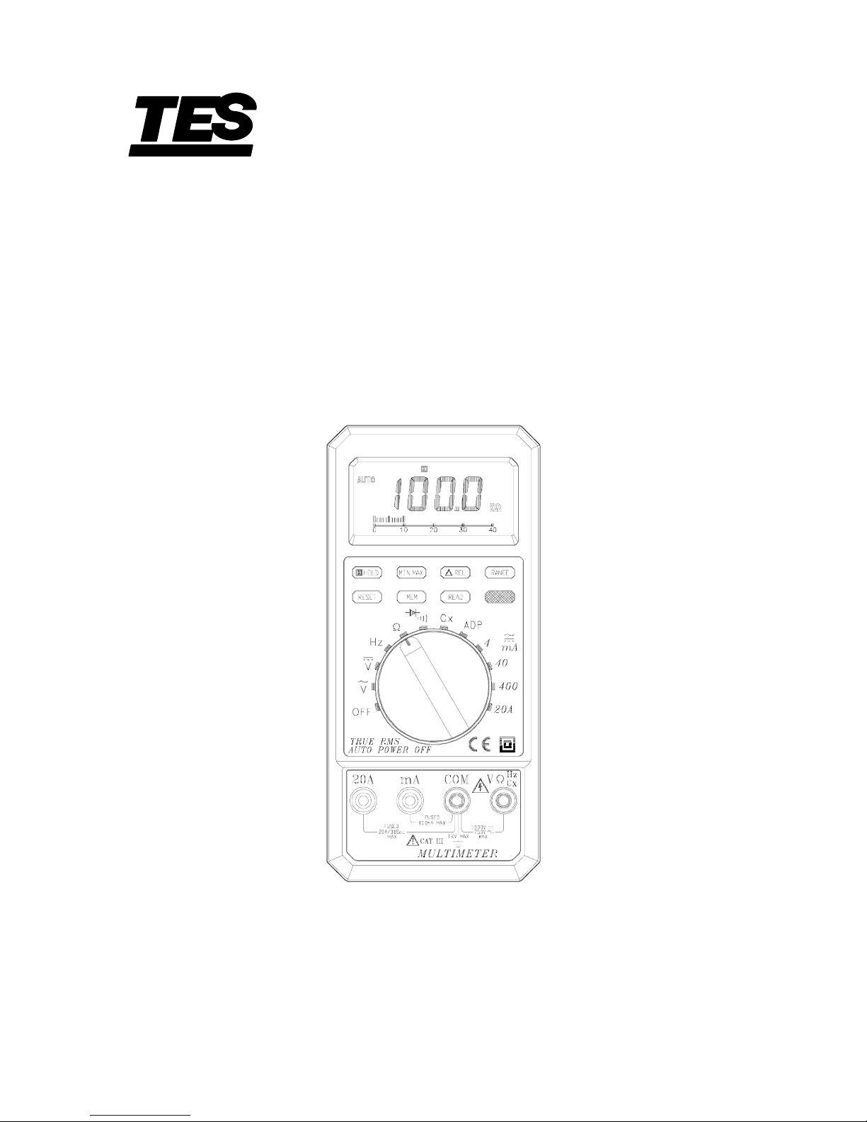
AUTO-RANGING
TRUE RMS MULTIMETER
TES-2620
INSTRUCTION MANUAL
TES ELECTRICAL ELECTRONIC CORP.
Page 2

CONTENTS
TITLE
PAGE
1. SAFETY INFORMATION .............................................. 1
2. FEATURES ................................................................... 2
3. SPECIFICATIONS ......................................................... 2
3-1 General Specifications ............................................ 2
3-2 Electrical Specifications .......................................... 5
4. PARTS & CONTROLS ................................................... 9
4-1 Name Of Parts And Positions ................................. 9
4-2 Precautions And Preparations For
Measurement.......................................................... 13
4-3 DC Voltage Measurements ..................................... 13
4-4 AC Voltage Measurements ..................................... 14
4-5 DC Current Measurements ..................................... 14
4-6 AC Current Measurements ..................................... 15
4-7 Capacity Measurement ........................................... 15
4-8 Continuity Measurement & Diodes Test ................. 16
4-9 Resistance Measurement ....................................... 17
4-10 Frequency Measurement ...................................... 17
4-11 TRMS Measurements ........................................... 17
4-12 Adaptive ( ADP ) Measurement ............................ 19
5 BATTERY & FUSE REPLACEMENT .............................. 19
5-1 Battery Check-Up & Replacement .......................... 19
5-2 FUSE Replacement ................................................ 19
Page 3
1
1. SAFETY INFORMATION
Read the following safety information carefully before attempting to
operate or service the meter.
To avoid damages to the instrument do not apply the signals which
exceed the maximum limits shown in the technical specifications tables.
Never measure current while the test leads are inserted into the input jacks.
Do not use the meter or test leads if they look damaged. Use extreme
caution when working around bare conductors or bus bars.
Accidental contact with the conductor could result in electric shock.
Use the meter only as specified in this manual ; otherwise, the
protection provided by the meter may be impaired.
Read the operating instructions before use and follow all safety
information.
Caution when working with voltages above 60V DC or 30 V AC RMS.
Such voltages pose a shock hazard.
Before taking resistance measurements or testing acoustic continuity,
disconnect circuit from main power supply and all loads from the circuit.
Safety symbols:
Caution refer to this manual before using the meter.
Dangerous voltages.
Meter is protected throughout by double insulation or reinforced
insulation.
When servicing, use only specified replacement parts.
Comply with EN-61010-1
Page 4

2
2. FEATURES
3-3/4 Digital LCD with Bar-graph
True RMS on ACV and ACA measurement
Water- Proof ABS housing
Auto- Ranging on Volt, Ohm , Current, Frequency, and Capacitance
measurement
Auto-power - off
Also provides MAX / MIN recording; MEM and READ; REL and data
HOLD mode
Ohms, Diode, Audible continuity, Capacitance range with input
Overload protection to 600Vrms
20A / 600V high energy fuse protection on 20A AC/DC
Flip - up stand
3 SPECIFICATIONS
3-1 General Specifications
Environment conditions
:
Installation Categories II
Pollution Degree 2
Altitude up to 2000 meters
Indoor use only
Relatively humidity 80% max.
Operation Ambient 0〜40℃
Maintenance & Clearing:
Repairs or servicing not covered in this
manual should only be performed by
qualified personnel.
Periodically wipe the case with a dry cloth.
Do not use abrasives or solvents on this
instruments.
Operating Principle
:
Dual slope integration
Numerical Display :
3 3/4 digit liquid crystal display (LCD)
maximum reading 3999 and Bar-graph
indication
.
Page 5

3
Unit and Sign Display:
■
Decimal point
AC
Alternating current or voltage
DC
Direct current or voltage
V
Volt
mV
Millivolt ( 1×10⁻³ volt )
A
Ampere ( amp ). Current
mA
Milliampere ( 1×10⁻³ amp )
Ω
Ohm. Resistance
KΩ
Kilohm ( 1×10
3
ohm ). Resistance
MΩ
Megohm ( 1×10
6
ohm ). Resistance
KHz
Kilohertz ( 1×10³ cycles / sec ).
Frequency
Hz
Hertz ( 1 cycle / sec). Frequency
uF
Microfarads ( 1×10⁻⁶ Farad ).
Capacitance
nF
Nanofarads ( 1×10⁻⁹ Farad ).
Capacitance
Page 6
4
Diode
Continuity Beeper
Low Battery
Negative polarity
Auto
Autorange
Manu
Manual Range
△
REL
Relative Reading
MEM
Memory Reading
Date Hold
Page 7

5
MIN
Minimum Reading
MAX
Maximum Reading
Range Selection : All ranges are measured by single Range
Switch operation.
Over Range Indication
:
LCD will show a “4” flashing in the highest
position accompanied with a continuous
beeper.
Low Battery Indication
:
The is displayed when the battery
voltage drops below the operating voltage.
Sampling Rate
:
20 times/sec of Bar-graph indication, 2
times/sec of digital display.
Power Source
:
2pcs of “ AA “ 1.5V Battery
Battery Life
:
400hrs approx.
Polarity
:
Automatic polarity “ “ displays for negative
input
Operating Temperature
:
0℃ to 40℃ ( 32℉ to 104℉ )
and Humidity below 80% RH
Storage Temperature
:
-10℃ to 60℃ ( 14℉ to 140℉ )
and Humidity below 70% RH
Dimensions
:
184 (L)
×
82 (W) × 42(H) mm
Weight
:
Approx. 375g
Accessories
:
Test leads , Spare fuse ( 0.5A/250V ) , Battery ,
Instruction manual, etc.
Page 8

6
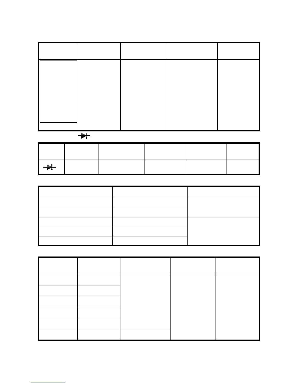
3-2 Electrical Specifications
Accuracies are ±(...% of reading + ...digits) at 23
℃±5℃
,below 80% RH.
DC Voltage : ( Autoranging & Manual range )
Range Resolution Accuracy
Input
Impedance
Overload
Protection
400mV 100uV
> 100M
Ω
4V 1mV
≒
11MΩ
40V 10mV
400V 100mV
1000V 1V
0.5%+1
≒
10MΩ
DC1100V
AC 800V
AC Voltage ( Autorange & Manual range ) True RMS
Range Resolution Accuracy
Input
Impedance
Overload
Protection
Frequency
Response
400mV 100uV
≥
100M
Ω
50 ∼ 60Hz
4V 1mV
≒
11MΩ
40V 10mV
400V 100mV
1.2%+5
750V 1V 1.5%+5
≒
10MΩ
DC1100V
AC 800V
40 ∼450Hz
※
400 mV only manual range.
Additional Crest Factor Errors ( non-sinecure )
Crest Factor Error ( % of reading )
1-3 1%
3-5 4.5%
※
[ For frequencies at 50/60 Hz, slow AC filter specified for sinecure input
only. ]
※
Response time : 5 seconds max, to rated accuracy in the selected range.
Page 9
7
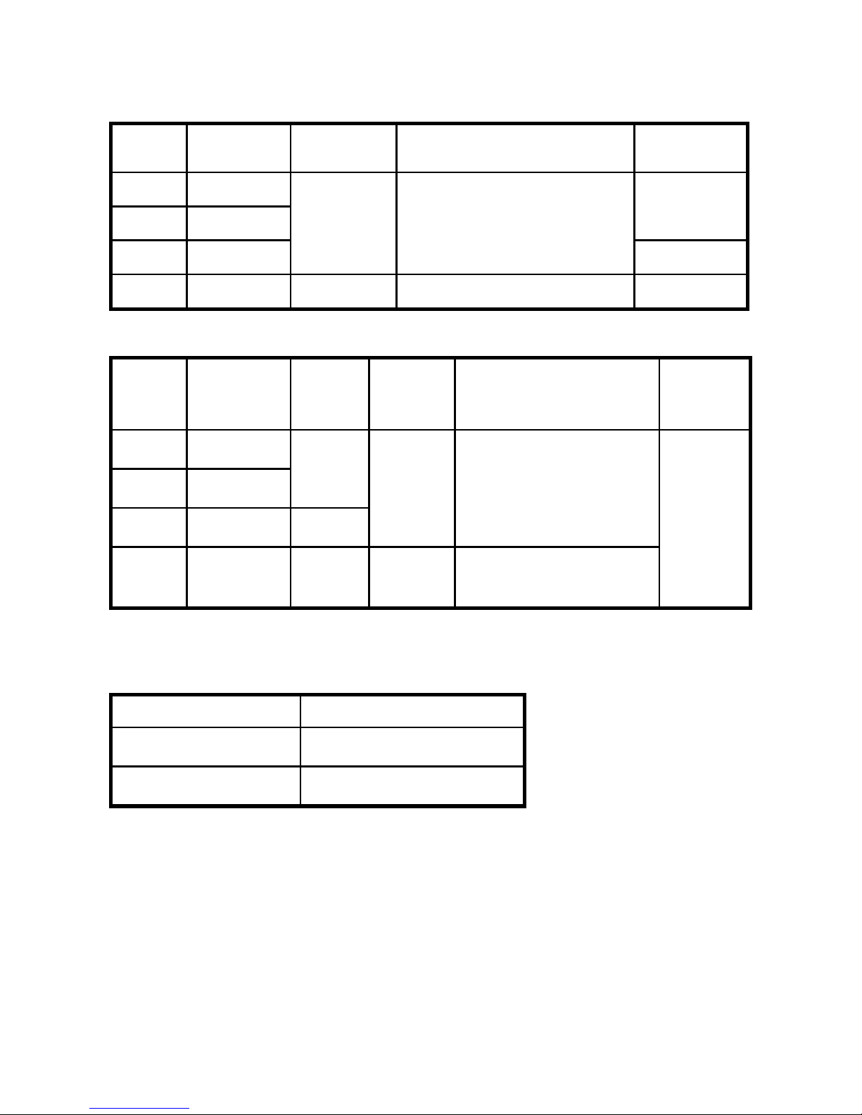
DC Current : ( manual range )
Range Resolution Accuracy Input Impedance
Burden
Voltage
4mA 1uA
40mA 10uA
0.45V
400mA 100uA
1%+1 0.5A / 250V fuse
0.65V
20A 10mA 1.5%+2
20A / 600V high energy fuse
1.3V
AC Current : (manual range ) True RMS
Range Resolution
Burden
Voltage
Accuracy Input Impedance
Frequenc
y
Response
4mA 1uA
40mA 10uA
0.45V
400mA 100uA 0.65V
1.5%+5 0.5A / 250V fuse
20A 10mA 1.3V 2%+5
20A / 600V high energy
fuse
40Hz to
500Hz
※
Conversion type : AC coupled, TRMS measurement.
Additional Crest Factor Errors ( non-sinecure )
Crest Factor Error ( % of reading )
1-3 1%
3-5 4.5%
※
[ For frequencies at 50/60 Hz, slow AC filter specified for sinecure input
only. ]
※
Response time : 5 seconds max, to rated accuracy in the selected range.
Page 10
8
Audible Continuity:
Range Resolution
Open Circuit
Voltage
Continuity
Beeper
Overload
Protection
0.1
Ω
≤
0.5V
≤
Approx. 40
Ω
600Vrms
Diode Test: ( )
Range Resolution
Short Circuit
Current
Accuracy
Open Circuit
Voltage
Overload
Protection
1mV 0.8mA typical 1%+ 2 3V 600Vrms
Capacitance (Cx): (Autoranging & Manual range )
Range Resolution Accuracy
4nF 1pF
40nF 10pF
1.5%+ 20
400nF 100pF
4uF 1nF
40uF 10nF
1.5%+ 10
Resistance: ( Autoranging & Manual range )
Range Resolution Accuracy
Open Circuit
Voltage
Overhead
protection
400Ω 100mΩ
4KΩ 1
Ω
40KΩ 10Ω
400KΩ 100Ω
4MΩ 1KΩ
0.75%+ 3
40MΩ 10KΩ
1.5%+ 5
≤
0.5V
600Vrms
Page 11
9
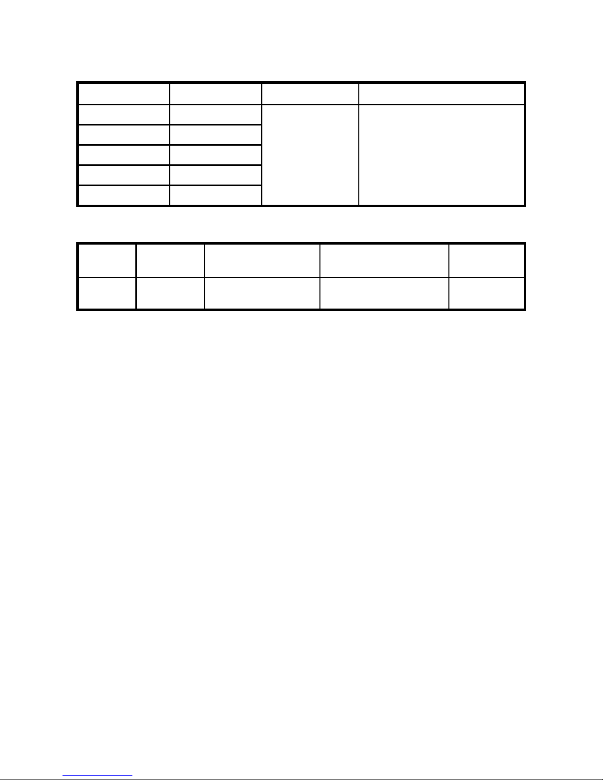
Frequency (Hz): ( Autoranging )
Range Resolution Accuracy Sensitivity
100HZ 0.01HZ
1KHZ 0.1HZ
10KHZ 1HZ
100KHZ 10HZ
500KHZ 100HZ
0.1%+ 2
100mV / 1V / 10V
(By Range Button Selector )
ADP
Function Input Resolution Accuracy
Overhead
Protection
ADP
400mV
DC
Full Scale
1 COUNT/0.1mV
±
0.5% of rdg ±2LSD
600Vrms
Page 12
10
4. PARTS & CONTROLS
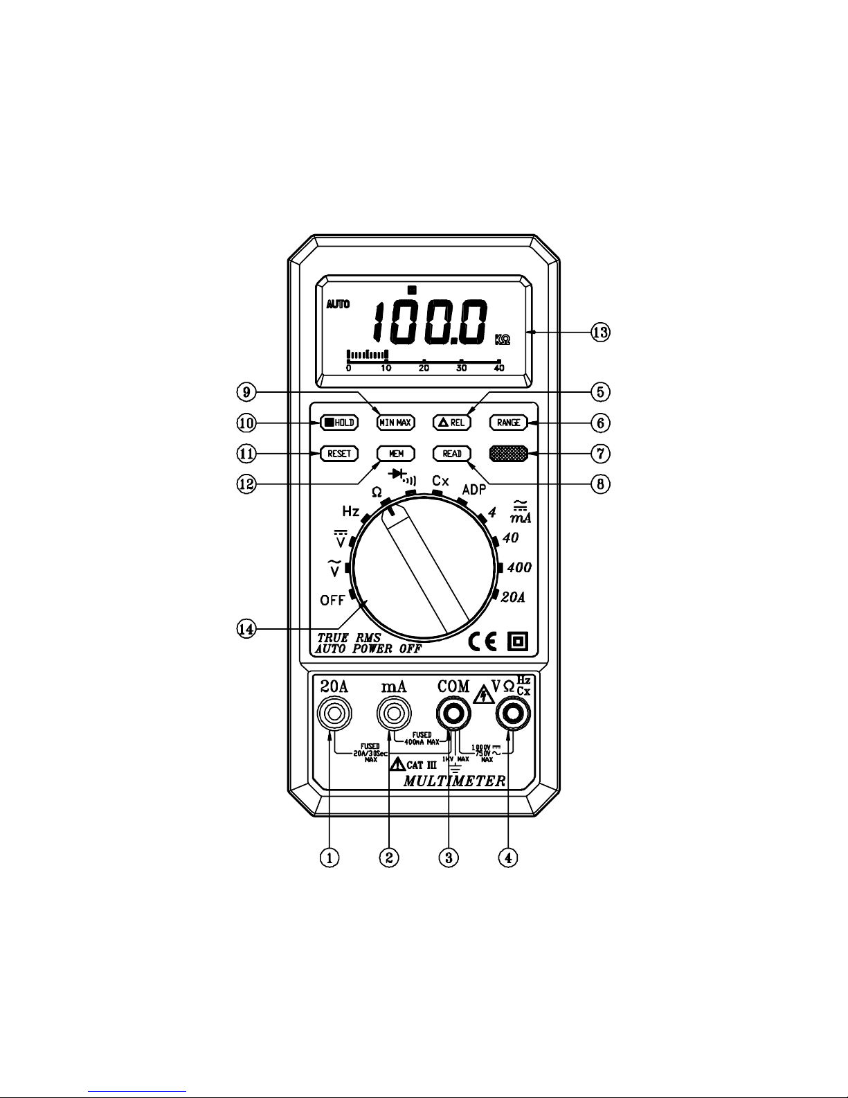
4-1 NAME OF PARTS AND POSITIONS:
Page 13

11
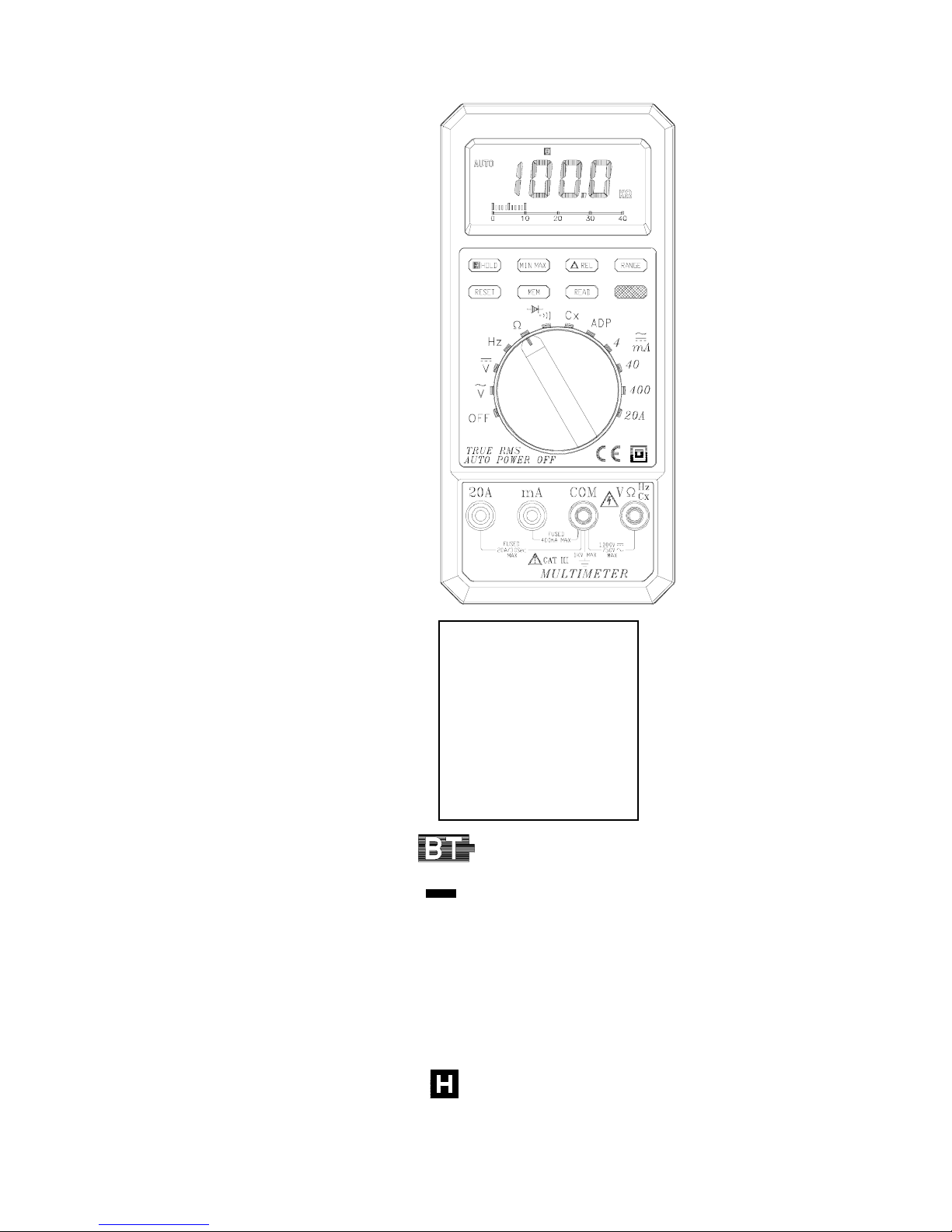
1. 20A Measuring Connector
To connect positive lead ( red test lead ) for current measurement
below 20A.
2. mA Measuring Connector
To connect positive lead ( red test lead ) for current measurement 400mA.
3. COM Measuring Connector
To connect negative lead ( black test lead ) for voltage, current, resistance,
frequency, Diode, continuity, capacitor, ADP measurement.
4. V
Ω
Hz Cx Measuring Connector
To connect positive lead ( red test lead ) for voltage, resistance, frequency,
diode, continuity, capacitor, ADP measurement.
5. Relative Reading Button
Press
△
REL button to enter the Relative mode. Zero the display , and
store the displayed reading as a reference value. Press and hold down
△
REL button for 2 seconds to exit the Relative mode.
6. Auto-Range & Manual-Range Button
Press RANGE to select the Manual Range mode and turn off the AUTO
annunciator. ( The meter remains in the range it was in when manual
range is selected ).
In the Manual Range mode, each time you press RANGE button, the range
( and the input range annunciator ) increases stop by step , and a new
value is displayed.
If you are already in the highest range, the meter “ wraps around “ to the lowest
range. ( In the Frequency counter mode, pressing RANGE manually
selects the sensitivity range. ) To exit the Manual Range mode and
return to Auto Range mode. Press and hold down RANGE for 2
seconds, the AUTO annunciator turns back on.
Page 14

12
7. AC/DC Current Select and Buzzer / Diode function Select and Cancel
Auto- Power-OFF function Button:
To select function DC or AC current.
To select function buzzer or Diode.
Cancel Auto-Power-OFF function : Press and Hold down the red
button to turn the rotary switch from OFF to any function position
about two seconds.
8. Read Button
Reading out at the storage memory value.
9. Minimum & Maximum Recording Button
Press MIN/MAX to enter the MIN, MAX Recording mode ( manual range
only ). Select the proper range before selecting MIN MAX to ensure
that the min/max reading will not exceed the measurement range.
Press once to select MIN. Press again to select MAX. and press again
to release MIN/MAX recording function.
10. Date Hold (
) Button
Press it once to hold the measured value in dark place when reading or
recording is difficult, press it again to release the holding status.
11. Reset Button
Erase memory and reset function.
12. MEM Button
Press MEM for Recording LCD value and function to memory.
13. LCD Display
Measured values, unit, symbols, and decimal points are displayed.
14. Range Selector Switch
For power on and power off and selection of desired range.
Page 15
13
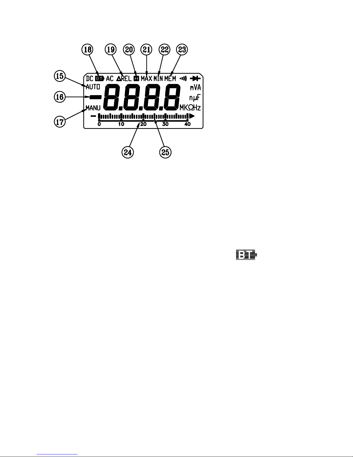
15. Auto-range Mode
Meter is in the autorange mode and will automatically select the range
with the best resolution. Meter powers-on in autorange mode.
16. Negative Polarity
Automatically indicating negative inputs.
17. Manual-range Mode indicator.
18. Low Battery
As battery power is not sufficient. LCD will display
.
19. Relative Mode indicator.
20. Data Hold indicator.
21. Maximum Value in MAX Recording Mode
The value displayed is the maximum reading taken since the MAX
Recording mode was entered.
22. Minimum Value in MIN Recording Mode
The value displayed is the minimum reading taken since the MIN
Recording mode is entered.
23. Memory Mode indicator.
24. Analog Display Scale.
25. Analog Display.
Page 16

14
4-2 PRECAUTIONS AND PREPARATIONS FOR MEASUREMENT
(1) DO NOT attempt to take any voltage or current measurement that
maybe exceed the maximum range of this instrument.
(2) Be sure that battery is correctly placed in the case and connected
to the battery snap.
(3) Make certain the range selected is greater than circuit current or
voltage prior to attempting a measurement. Also, Changing range
always breaks contact from the circuit with one of the test leads.
(4) Check the input terminal position for red test lead depending on
measurement ranges.
(5) DO NOT measure anything before the rear cover of Multimeter is
not secured.
(6) When finishing the measurement, Switch off the power.
(7) Be sure remove the battery when it is not to be used for a long
time to avoid leakage problem.
(8) DO NOT use or store the instrument in a high temperature, high
humidity environment.
(9) DO NOT check resistance in a circuit while power is on or before
circuit capacitors are discharged.
4-3 DC Voltage Measurements
WARNING
Maximum Input Voltage of DC VOLT Range is 1000VDC. Do not
attempt to take any voltage measurement that maybe exceed
1000VDC to avoid electrical shock hazard and / or damage to the
instrument.
Page 17

15
(1) Connect red test lead to “ VΩ “terminal and black test lead to
“ COM” terminal.
(2) Set Range Switch to
V
range.
(3) Connect Test Prods of test leads IN PARALLEL to the circuit
being measured.
(4) Read the Voltage value on LCD.
4-4 AC Voltage Measurement ( True RMS Measurement )
WARNING
Maximum Input Voltage of AC VOLT Range is 750VAC. Do not
attempt to take any voltage measurement that maybe exceed
750VAC to avoid electrical shock hazard and / or damage to the
instrument
.
(1) Connect red test lead to “V
Ω
“ terminal and black test lead to
“COM” terminal.
(2) Set Range Switch to
V
range.
(3) Connect Test Prods of test leads IN PARALLEL to the circuit
being measured.
(4) Read the Voltage value on LCD.
4-5 DC Current Measurement
(1) Connect red test lead to “ mA “ Terminal for Current
measurements up to 400mA. ( For measuring Current between
400mA to 20A, Connect red test lead to “ 20A “ terminal.) Connect
black test lead to “ COM “ terminal.
Page 18

16
(2) Set Range Switch to desired A range. and press AC / DC Switch
to DC function.
(3) Cut the power to the circuit being tested and Connect the
instrument IN SERIES with the circuit , with the black test lead on
the negative
side and the red lead on the positive side
being measured.
(4) Apply power and read the current value on LCD.
4-6 AC Current Measurement ( True RMS Measurement )
(1) Connect red test lead to the “mA“ Terminal for Current
measurements up to 400mA. ( For measuring Current between
400mA to 20A, Connect red test lead to “20A“ terminal.) Connect
black test lead to “ COM “ terminal.
(2) Set Range Switch to desired A range. And press AC / DC Switch
to AC function.
(3) Cut the power to the circuit being tested and Connect the
instrument INSERIES with the circuit ; with the black test lead on
the negative
side and the red lead on the positive side
being measured.
(4) Apply power and read the current Value on LCD.
4-7 Capacity Measurement
(1) Set Range Switch to capacitor Cx position.
(2) Insert the capacitor pins into Cx and COM terminal for
measurement..
(3) Press
△
REL to zero the display and automatically subtract the
residual meter and test lead capacitance.
(4) Read the capacity on LCD.
Page 19
17
4-8 Continuity Measurement & Diode test
Press “ Red “ button to select " " or " " function.
WARNING
Before taking any in- circuit measurement, remove power from
the circuit being tested and discharge all capacitors in the
circuit.
CONTINUITY MEASUREMENT
(1) Connect red test lead to the " VΩ " terminal and black test lead to
the " COM " terminal.
(2) Set range switch to the "
" position.
(3) Remove power from the circuit being tested and discharge all
capacitors.
(4) Connect Test prods of test leads in the circuit being measured.
(5) When the test lead to the circuit is below 40
Ω
It will be
indicated by a continuous beeping.
Note:
Continuity test is available to check open / short of the
circuit.
DIODE TEST
(1) Connect red test lead to the " VΩ " terminal and black test lead to
the " COM" terminal.
(2) Set range switch to the diode test position "
" .
(3) Connect the red test lead to the anode side and black test lead to
the cathode side of the diode being tested.
(4) Read forward voltage ( Vf ) value on LCD.
(5) If the test leads are connected rather than according to procedure
(4), the digital reading should nearly equal to the reading in the
open circuit condition. This can be used for distinguishing anode
and cathode poles of a diode.
Page 20

18
4-9 Resistance Measurement
WARNING
Before taking any in-circuit resistance measurement, remove
power from the circuit being tested and discharge all Capacitors.
(1) Connect red test lead to “ VΩ “terminal and black test lead to
“ COM” terminal.
(2) Set Range Switch to
Ω
range.
(3) Connect Test Lead to the Circuit being measured and read the
resistance Value on LCD.
4-10 Frequency Measurement
(1) Set Range Switch to Hz range.
(2) Connect red test lead to “ V/
Ω
/Hz “ terminal and black test lead to
“ COM” terminal.
(3) Connect Test prods of test leads to the circuit being measured.
(4) Read the frequency value ( Hz ) on LCD.
4-11 TRMS MEASUREMENTS
This model is a True- RMS model. When measuring AC signals,
undistorted sine waves are rarely encountered.
On the contrary, the non- sinusoidal waves, triangle and square
waves, as well as noise affected waves are very common.
With conventional average- sensing meters, the measurement of
such wave forms is impossible because of the great error introduced
by the AC/DC half-wave rectifier.
The measurement signal is converted into the average value and
then multiplied by 1.11, and displayed as rms value of the sine
wave.
Page 21
19
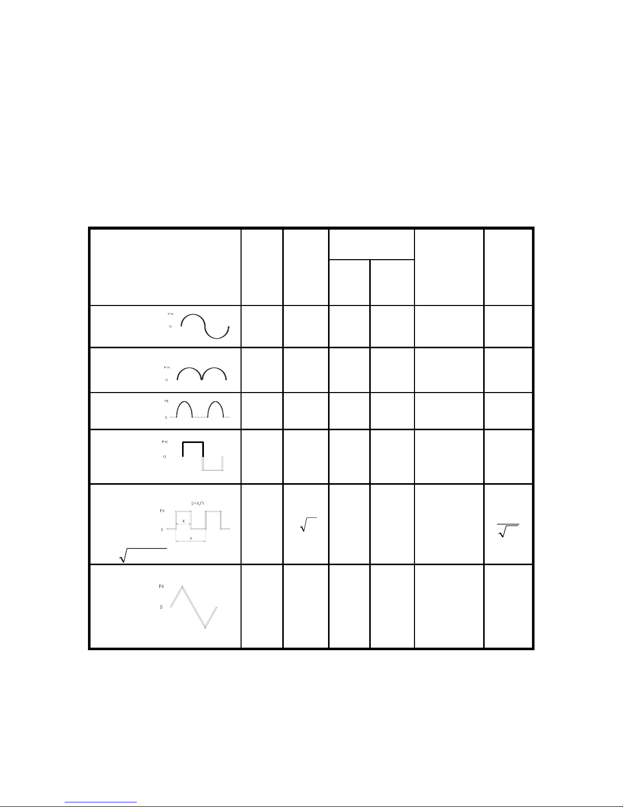
If the input differs significantly from a sine wave, the reading is
incorrect as a different conversion factor would relate the average
value of the signal to its rms value (see table as below).
Correct measurements of non- sinusoidal wave forms can be made
directly with the true- RMS models.
The parameter which defines the degree of distortion of the wave
form and influences the measurement accuracy is the crest- factor
defined as the ratio of the peak value to the rms value.
AC Coupling
Input
Wave form
Peak
value
Vdc
+Vac
(TRMS)
Vac
Average
value
Vdc
Crest
factor
Sine wave
1.414 1.000 1.000 1.000 0 1.414
Full-wave
1.414 1.000 0.435 0.421 0.900 1.414
Half - wave
2.000 1.000 0.771 0.764 0.636 2
Square wave
1.000 1.000 1.000 1.110 0 1
Pulse
D= X / Y
KDD=−
2
2.000
2
D
2K 2.22K 2D
1
D
Triangle
wave
1.732 1.000 1.000 0.960 0 1.732
Page 22
20
4-12 Adaptive ( ADP ) Measurement
(1) Connect the BLACK test lead to the COM terminal and the RED
test lead to the “ V-
Ω
-ADP “ terminal.
(2) Set the rotary switch to “ ADP “ position.
(3) Connect the test leads across the source or load under
measurement.
Note: When making ADP measurements, the digital display will
indicate 10 counts for every mV
DC
input. e.g.A reading of 100
indicates a 10mV
DC
input.
5. BATTERY & FUSE REPLACEMENT
WARNING
To prevent electrical hazard or shock, turn off multimeter and
disconnect test leads before removing back cover.
5-1 Battery Check-Up & Replacement
(1) As battery power is not sufficient. LCD will display “
“.
Replacement with Two new batteries type 1.5V is required.
(2) Set Range Switch to “ OFF “ position. Use a screwdriver to
unscrew the screw secured on the rear cover. Take out the
battery and replace them with two new batteries type 1.5V.
(3) Place back the rear cover and secure it by a screw.
5-2 FUSE Replacement
(1) Set Range Switch to “ OFF “ position. Use a screwdriver to
unscrew the screw secured on rear cover. Take out the open fuse
and replace it with a new fuse rate 0.5A/250A ( or 20A/600V ) of
fast blow type.
(2) Place back the rear cover and secure it by a screw.
Page 23

TES ELECTRICAL ELECTRONIC CORP.
Add: 7F, No. 31, Lane 513, Rui Guang Road, Neihu Dist.
Taipei. Taiwan, R. O. C.
Tel : (02) 2799-3660 Fax : 886-2-2799-5099
E-Mail : [email protected] http://www.tes.com.tw
Mar-2000-2
 Loading...