

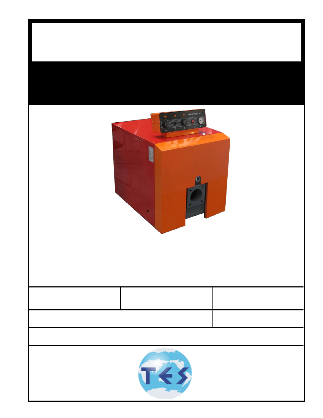
TES Series Installation, Operating And Service Instructions
TES
DNAGNITAREPO,NOITALLATSNI
ROFSNOITCURTSNIECIVRES
®
SEIRES
GAS/OIL
GASgGASAS
RELIOBDERIF-
,reliobnonoitamrofnignikeesnehW.rotcartnocgnitaehruoyllac,reliobotsriaperroecivresroF
.lebaLgnitaRnonwohssarebmuNlaireSdnarebmuNledoMrelioBedivorp
rebmuNledoMrelioB
rotcartnoCgnitaeH
sserddA
rebmuNlaireSrelioB etaDnoitallatsnI
rebmuNenohP

IMPORTANT INFORMATION - PLEASE READ THIS PAGE CAREFULLY
1. THIS BOILER HAS LIMITED WARRANTIES, COPIES OF WHICH ARE PRINTED ON THE BACK COVER OF THIS
MANUAL.
2. THIS BOILER IS SUITABLE FOR INSTALLATION ON COMBUSTIBLE FLOORING. BOILER CAN NOT BE INSTALLED
ON CARPETING.
3. ALL BOILERS MUST BE INSTALLED IN ACCORDANCE WITH NATIONAL, STATE AND LOCAL PLUMBING, HEATING
AND ELECTRICAL CODES AND THE REGULATIONS OF THE SERVING UTILITIES WHICH MAY DIFFER FROM THIS
MANUAL. AUTHORITIES HAVING JURISDICTION SHOULD BE CONSULTED BEFORE INSTALLATIONS ARE MADE.
IN ALL CASES, REFERENCE SHOULD BE MADE TO THE FOLLOWING STANDARDS:
USA BOILERS
A. Current Edition of American National Standard ANSI/NFPA 31, “Installation of Oil Burning Equipment”, for clearances between boiler, vent connector and
combustible material.
B. Current Edition of American National Standard ANSI/NFPA 211, “Chimneys, Fireplaces, Vents, and Solid Fuel Burning Appliances”, For Chimney require-
ments, type of venting material and clearances between vent connector pipe and combustible materials.
C. Current Edition of American Society of Mechanical Engineers ASME CSD-1, “Controls and Safety Devices for Automatically Fired Boilers”, for assembly
and operations of controls and safety devices.
A. Current Edition of Canadian Standards Association CSA B139, “Installation Code for Oil Burning Equipment”, for recommended Installation Practices.
4. ALL HEATING SYSTEMS SHOULD BE DESIGNED BY COMPETENT CONTRACTORS AND ONLY PERSONS
KNOWLEDGEABLE IN THE LAYOUT AND INSTALLATION OF HYDRONIC HEATING SYSTEMS SHOULD ATTEMPT
INSTALLATION OF ANY BOILER.
5. THE BOILER MUST BE CONNECTED TO AN APPROVED CHIMNEY IN GOOD CONDITION. SERIOUS PROPERTY
DAMAGE COULD RESULT IF THE BOILER IS CONNECTED TO A DIRTY OR INADEQUATE CHIMNEY. THE INTERIOR
OF THE CHIMNEY FLUE MUST BE INSPECTED AND CLEANED BEFORE THE START OF THE HEATING SEASON
AND SHOULD BE INSPECTED PERIODICALLY THROUGHOUT THE HEATING SEASON FOR ANY OBSTRUCTIONS. A
CLEAN AND UNOBSTRUCTED CHIMNEY FLUE IS NECESSARY TO ALLOW NOXIOUS FUMES THAT COULD CAUSE
INJURY OR LOSS OF LIFE TO VENT SAFELY AND WILL CONTRIBUTE TOWARD MAINTAINING THE BOILER’S
EFFICIENCY.
6. READ THE LITERATURE ENCLOSED BY THE MANUFACTURER WITH THE VARIOUS ACCESSORY DEVICES. THESE
ACCESSORY DEVICES MUST BE INSTALLED AND USED ACCORDING TO THE RECOMMENDATIONS OF THE
MANUFACTURER.
7. IT IS THE RESPONSIBILITY OF THE INSTALLING CONTRACTOR TO SEE THAT ALL CONTROLS ARE CORRECTLY
INSTALLED AND ARE OPERATING PROPERLY WHEN THE INSTALLATION IS COMPLETED.
8. FOR OPTIMUM PERFORMANCE AND SERVICEABILITY FROM THIS UNIT ADHERE TO THE FOLLOWING
RECOMMENDATIONS:
A. DO NOT TAMPER WITH THE UNIT OR CONTROLS. Retain your contractor or a competent serviceman to assure that the unit is properly adjusted and
maintained.
B. Clean Firetubes at least once a year - preferably at the end of the heating season to remove soot and scale. Inside of Combustion Chamber should also be
cleaned at the same time.
C. Have Oil Burner and Controls checked at least once a year or as may be necessitated.
CANADA BOILERS
WARNING
THIS BOILER IS DESIGNED TO BURN NO. 2 FUEL OIL ONLY. DO NOT USE GASOLINE, CRANKCASE
DRAININGS, OR ANY OIL CONTAINING GASOLINE. NEVER BURN GARBAGE OR PAPER IN THIS BOILER.
DO NOT CONVERT TO ANY SOLID FUEL (I.E. WOOD, COAL) OR GASEOUS FUEL (I.E. NATURAL GAS, LP/
PROPANE). ALL FLAMMABLE DEBRIS, RAGS, PAPER, WOOD SCRAPS, ETC., SHOULD BE KEPT CLEAR OF
THE BOILER AT ALL TIMES. KEEP THE BOILER AREA CLEAN AND FREE OF FIRE HAZARDS.
All boilers equipped with burner swing door have a potential hazard which can cause severe property damage,
personal injury or loss of life if ignored. Before opening swing door, turn off service switch to boiler and
disconnect two halves of Burner Swing Door Interlock wiring harness to prevent accidental ring of burner
outside the combustion chamber. Be sure to tighten swing door fastener completely and reconnect two
halves of Burner Swing Door Interlock when service is completed
CAUTION
This boiler contains controls which may cause the boiler to shut down and not restart without service. If
damage due to frozen pipes is a possibility, the heating system should not be left unattended in cold weather;
or appropriate safeguards and alarms should be installed on the heating system to prevent damage if the
boiler is inoperative.
2
IMPORTANT
Before starting to install this oil boiler, read these instructions carefully. Keep instructions in legible condition
and posted near oil boiler for reference by owner and service technician.
TAbLE OF CONTENTS
I. General Information ..................................3
II. Installation Instructions ............................
5
IV. Boiler Cleaning
.............................................
14
III. Operating and Service Instructions ..........
I. General Information
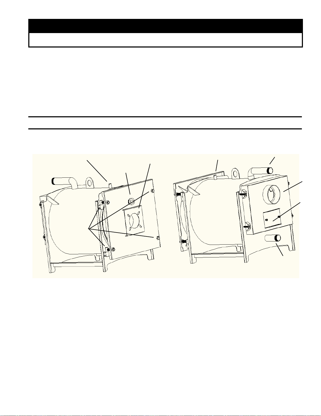
3-sensor pocket
Burner mount position
Fire inspection hole
Door hinges
11
Water outlet
3-sensor pocket
Chimney
Cleaning access
Figure 1: TES® Packaged Boiler
1
. INSPECT SHIPMENT carefully for any signs of
damage.
A. ALL EQUIPMENT is carefully manufactured,
inspected and packed. Our responsibility ceases
upon delivery of crated Boiler to the carrier in good
condition.
B. ANY CLAIMS for damage or shortage in shipment
must be led immediately against the carrier by the
consignee. No claims for variances from, or
shortage in orders, will be allowed by the manufacturer unless presented within sixty (60) days after
receipt of goods.
Water Inlet
2
. LOCATE BOILER in front of nal position before
removing crate. See Figure 1.
A. LOCATE so that smoke pipe connection to chimney
will be short and direct. BOILER IS SUITABLE
FOR INSTALLATION ON COMBUSTIBLE
FLOOR. Boiler can not be installed on carpeting.
B. FOR BASEMENT INSTALLATION, provide a
solid base, such as concrete, if oor is not level or
if water may be encountered on oor around Boiler.
C. PROVIDE SERVICE CLEARANCE of at least 24”
clearance in front for servicing.
D. For minimum clearances to combustible materials
See Figure 2.
3
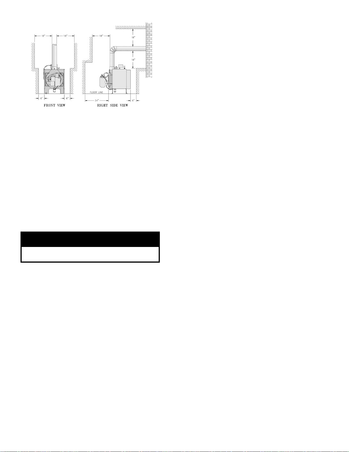
Figure 2: Minimum Installation Clearances To
Combustible Materials
NOTE 1: Listed clearances comply with American
National Standard ANSI/NFPA 31,
Installation of oil burning equipment.
NOTE 2: TES Series boilers can be installed in rooms
with clearances from combustible material as
listed above. Listed clearances can not be
reduced for alcove or closet installations.
NOTE 3: For reduced clearances to combustible
material, protection must be provided as
described in the above ANSI/NFPA 31
standard.
3. PROVIDE COMBUSTION AND VENTILATION
AIR. Local code provisions may apply and should be
referenced.
WARNING
Adequate combustion and ventilation air must be
provided to assure proper combustion.
A. Determine volume of space (boiler room). Rooms
communicating directly with the space in which the
appliances are installed, through openings not
furnished with doors, are considered a part of the
space.
Volume(ft
B. Determine total input of all appliances in the space.
Add inputs of all appliances in the space and round
the result to the nearest 1000 BTU per hour.
C. Determine type of space. Divide Volume by total
input of all appliances in space. If the result is
greater than or equal to 50 ft3/1000 BTU per hour,
then it is considered an unconned space. If the
result is less than 50 ft3/1000 BTU per hour then the
space is considered a conned space.
D. For boiler located in an unconned space of a
conventionally constructed building, the fresh air
3
) = Length(ft) x Width(ft) x Height(ft)
inltration through cracks around windows and
doors normally provides adequate air for combustion and ventilation.
E. For boiler located in a conned space or an uncon
ned space in a building of unusually tight con-
struction, provide outdoor air with the use of two
permanent openings which communicate directly or
by duct with the outdoors or spaces (crawl or attic)
freely communicating with the outdoors. Locate
one opening within 12 inches of top of space.
Locate remaining opening within 12 inches of
bottom of space. Minimum dimension of air
opening is 3 inches. Size each opening per
following:
Direct communication with outdoors.
(1)
Minimum free area of 1 square inch per 4,000
BTU per hour input of all equipment in space.
(2) Vertical ducts. Minimum free area of 1 square
inch per 4,000 BTU per hour input of all
equipment in space. Duct cross-sectional area
shall be same as opening free area.
(3) Horizontal ducts. Minimum free area of 1
square inch per 2,000 BTU per hour input of all
equipment in space. Duct cross-sectional area
shall be same as opening free area.
Alternate method for boiler located within
conned space. Use indoor air if two permanent openings communicate directly with
additional space(s) of sufcient volume such
that combined volume of all spaces meet
criteria for unconned space. Size each
opening for minimum free area of 1 square
inch per 1,000 BTU per hour input of all
equipment in spaces, but not less than 100
square inches.
F. Louvers and Grilles of Ventilation Ducts
(1) All outside openings should be screened and
louvered. Screens used should not be smaller
than 1/4 inch mesh. Louvers will prevent the
entrance of rain and snow.
(2) Free area requirements need to consider the
blocking effect of louvers, grilles, or screens
protecting the openings. If the free area of the
louver or grille is not known, assume wood
louvers have 20-25 percent free area and metal
louvers and grilles have 60-75 percent free
area.
(3) Louvers and grilles must be xed in the open
position, or interlocked with the equipment to
open automatically during equipment operation.
-
4
II. Installation Instructions
1.
REMOVE CRATE
A. Remove all fasteners at crate skid.
B. Lift outside container and remove all other inside
fittings.
2.
REMOVAL OF BOILER FROM SKID
A. Tilt boiler, "walk" boiler backward, and set rear legs
down on oor. Tilt boiler backward, pull skid
forward and set front legs down on edge of skid.
Install close coupling, tee, and plug in return
coupling, see Step 7 and Figure 1. Point tee toward
permanent return location.
B. Tilt boiler backward and remove skid. Be careful not
to damage Burner and Jacket.
3.
CHANGE HINGE POSITION if necessary.
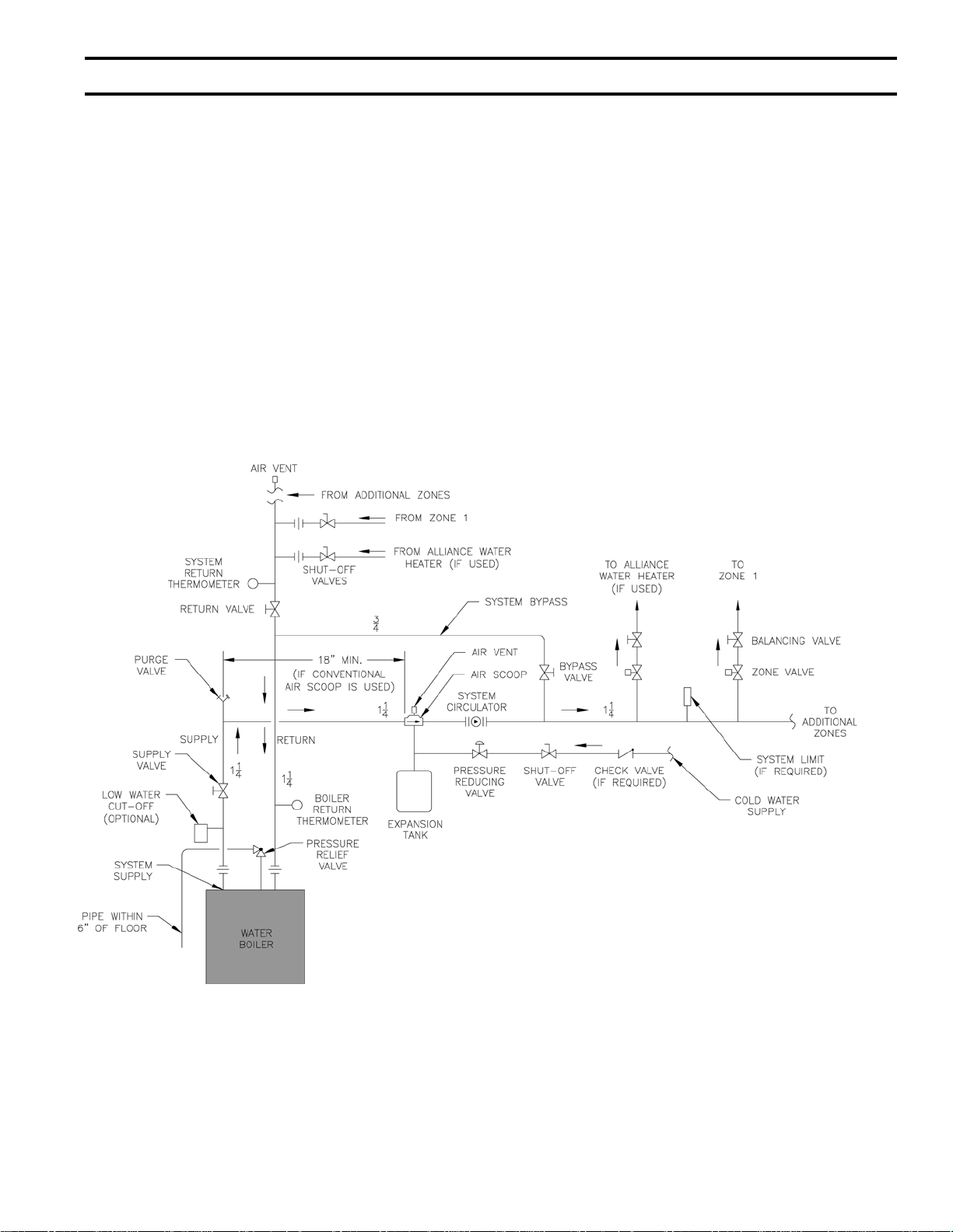
Figure 4: Recommended Water Piping for Zone Valve Zoned Heating Systems
5
 Loading...