

Page 1
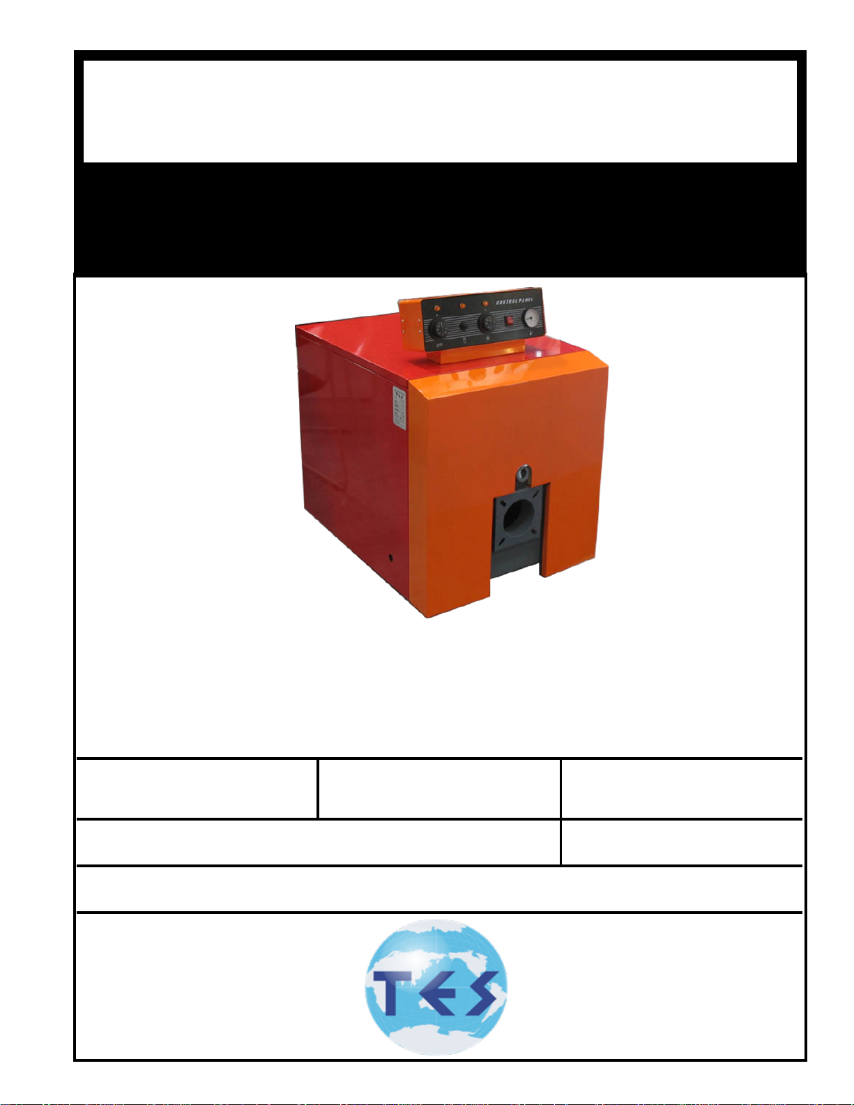
TES
DNAGNITAREPO,NOITALLATSNI
ROFSNOITCURTSNIECIVRES
®
SEIRES
GAS/OIL
GASgGASAS
RELIOBDERIF-
,reliobnonoitamrofnignikeesnehW.rotcartnocgnitaehruoyllac,reliobotsriaperroecivresroF
.lebaLgnitaRnonwohssarebmuNlaireSdnarebmuNledoMrelioBedivorp
rebmuNledoMrelioB
rotcartnoCgnitaeH
sserddA
rebmuNlaireSrelioB etaDnoitallatsnI
rebmuNenohP
Page 2

IMPORTANT INFORMATION - PLEASE READ THIS PAGE CAREFULLY
1. THIS BOILER HAS LIMITED WARRANTIES, COPIES OF WHICH ARE PRINTED ON THE BACK COVER OF THIS
MANUAL.
2. THIS BOILER IS SUITABLE FOR INSTALLATION ON COMBUSTIBLE FLOORING. BOILER CAN NOT BE INSTALLED
ON CARPETING.
3. ALL BOILERS MUST BE INSTALLED IN ACCORDANCE WITH NATIONAL, STATE AND LOCAL PLUMBING, HEATING
AND ELECTRICAL CODES AND THE REGULATIONS OF THE SERVING UTILITIES WHICH MAY DIFFER FROM THIS
MANUAL. AUTHORITIES HAVING JURISDICTION SHOULD BE CONSULTED BEFORE INSTALLATIONS ARE MADE.
IN ALL CASES, REFERENCE SHOULD BE MADE TO THE FOLLOWING STANDARDS:
USA BOILERS
A. Current Edition of American National Standard ANSI/NFPA 31, “Installation of Oil Burning Equipment”, for clearances between boiler, vent connector and
combustible material.
B. Current Edition of American National Standard ANSI/NFPA 211, “Chimneys, Fireplaces, Vents, and Solid Fuel Burning Appliances”, For Chimney require-
ments, type of venting material and clearances between vent connector pipe and combustible materials.
C. Current Edition of American Society of Mechanical Engineers ASME CSD-1, “Controls and Safety Devices for Automatically Fired Boilers”, for assembly
and operations of controls and safety devices.
A. Current Edition of Canadian Standards Association CSA B139, “Installation Code for Oil Burning Equipment”, for recommended Installation Practices.
4. ALL HEATING SYSTEMS SHOULD BE DESIGNED BY COMPETENT CONTRACTORS AND ONLY PERSONS
KNOWLEDGEABLE IN THE LAYOUT AND INSTALLATION OF HYDRONIC HEATING SYSTEMS SHOULD ATTEMPT
INSTALLATION OF ANY BOILER.
5. THE BOILER MUST BE CONNECTED TO AN APPROVED CHIMNEY IN GOOD CONDITION. SERIOUS PROPERTY
DAMAGE COULD RESULT IF THE BOILER IS CONNECTED TO A DIRTY OR INADEQUATE CHIMNEY. THE INTERIOR
OF THE CHIMNEY FLUE MUST BE INSPECTED AND CLEANED BEFORE THE START OF THE HEATING SEASON
AND SHOULD BE INSPECTED PERIODICALLY THROUGHOUT THE HEATING SEASON FOR ANY OBSTRUCTIONS. A
CLEAN AND UNOBSTRUCTED CHIMNEY FLUE IS NECESSARY TO ALLOW NOXIOUS FUMES THAT COULD CAUSE
INJURY OR LOSS OF LIFE TO VENT SAFELY AND WILL CONTRIBUTE TOWARD MAINTAINING THE BOILER’S
EFFICIENCY.
6. READ THE LITERATURE ENCLOSED BY THE MANUFACTURER WITH THE VARIOUS ACCESSORY DEVICES. THESE
ACCESSORY DEVICES MUST BE INSTALLED AND USED ACCORDING TO THE RECOMMENDATIONS OF THE
MANUFACTURER.
7. IT IS THE RESPONSIBILITY OF THE INSTALLING CONTRACTOR TO SEE THAT ALL CONTROLS ARE CORRECTLY
INSTALLED AND ARE OPERATING PROPERLY WHEN THE INSTALLATION IS COMPLETED.
8. FOR OPTIMUM PERFORMANCE AND SERVICEABILITY FROM THIS UNIT ADHERE TO THE FOLLOWING
RECOMMENDATIONS:
A. DO NOT TAMPER WITH THE UNIT OR CONTROLS. Retain your contractor or a competent serviceman to assure that the unit is properly adjusted and
maintained.
B. Clean Firetubes at least once a year - preferably at the end of the heating season to remove soot and scale. Inside of Combustion Chamber should also be
cleaned at the same time.
C. Have Oil Burner and Controls checked at least once a year or as may be necessitated.
CANADA BOILERS
WARNING
THIS BOILER IS DESIGNED TO BURN NO. 2 FUEL OIL ONLY. DO NOT USE GASOLINE, CRANKCASE
DRAININGS, OR ANY OIL CONTAINING GASOLINE. NEVER BURN GARBAGE OR PAPER IN THIS BOILER.
DO NOT CONVERT TO ANY SOLID FUEL (I.E. WOOD, COAL) OR GASEOUS FUEL (I.E. NATURAL GAS, LP/
PROPANE). ALL FLAMMABLE DEBRIS, RAGS, PAPER, WOOD SCRAPS, ETC., SHOULD BE KEPT CLEAR OF
THE BOILER AT ALL TIMES. KEEP THE BOILER AREA CLEAN AND FREE OF FIRE HAZARDS.
All boilers equipped with burner swing door have a potential hazard which can cause severe property damage,
personal injury or loss of life if ignored. Before opening swing door, turn off service switch to boiler and
disconnect two halves of Burner Swing Door Interlock wiring harness to prevent accidental ring of burner
outside the combustion chamber. Be sure to tighten swing door fastener completely and reconnect two
halves of Burner Swing Door Interlock when service is completed
CAUTION
This boiler contains controls which may cause the boiler to shut down and not restart without service. If
damage due to frozen pipes is a possibility, the heating system should not be left unattended in cold weather;
or appropriate safeguards and alarms should be installed on the heating system to prevent damage if the
boiler is inoperative.
2
Page 3
IMPORTANT
Before starting to install this oil boiler, read these instructions carefully. Keep instructions in legible condition
and posted near oil boiler for reference by owner and service technician.
TAbLE OF CONTENTS
I. General Information ..................................3
II. Installation Instructions ............................
5
IV. Boiler Cleaning
.............................................
14
III. Operating and Service Instructions ..........
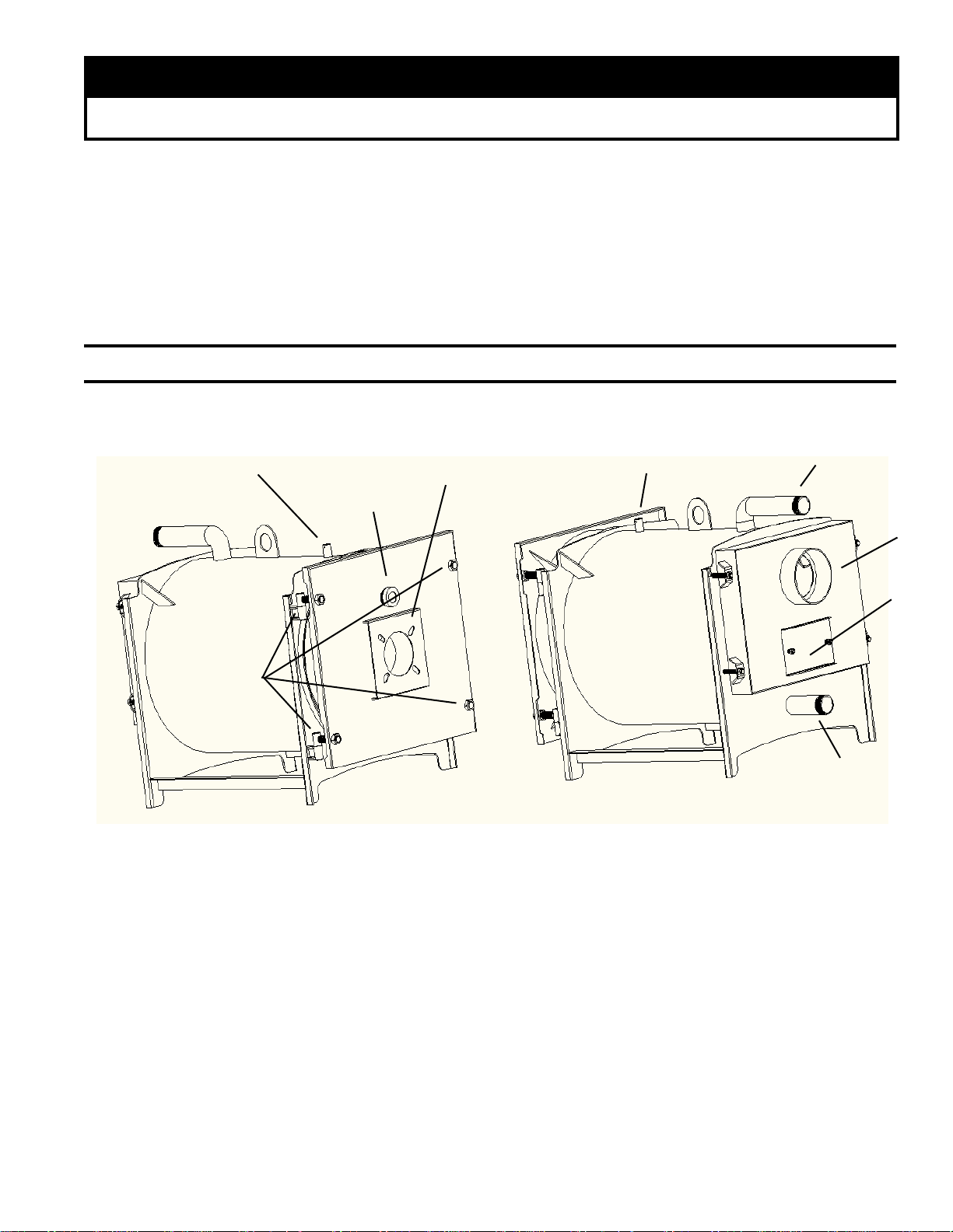
I. General Information
3-sensor pocket
Burner mount position
Fire inspection hole
Door hinges
11
Water outlet
3-sensor pocket
Chimney
Cleaning access
Figure 1: TES® Packaged Boiler
1
. INSPECT SHIPMENT carefully for any signs of
damage.
A. ALL EQUIPMENT is carefully manufactured,
inspected and packed. Our responsibility ceases
upon delivery of crated Boiler to the carrier in good
condition.
B. ANY CLAIMS for damage or shortage in shipment
must be led immediately against the carrier by the
consignee. No claims for variances from, or
shortage in orders, will be allowed by the manufacturer unless presented within sixty (60) days after
receipt of goods.
Water Inlet
2
. LOCATE BOILER in front of nal position before
removing crate. See Figure 1.
A. LOCATE so that smoke pipe connection to chimney
will be short and direct. BOILER IS SUITABLE
FOR INSTALLATION ON COMBUSTIBLE
FLOOR. Boiler can not be installed on carpeting.
B. FOR BASEMENT INSTALLATION, provide a
solid base, such as concrete, if oor is not level or
if water may be encountered on oor around Boiler.
C. PROVIDE SERVICE CLEARANCE of at least 24”
clearance in front for servicing.
D. For minimum clearances to combustible materials
See Figure 2.
3
Page 4
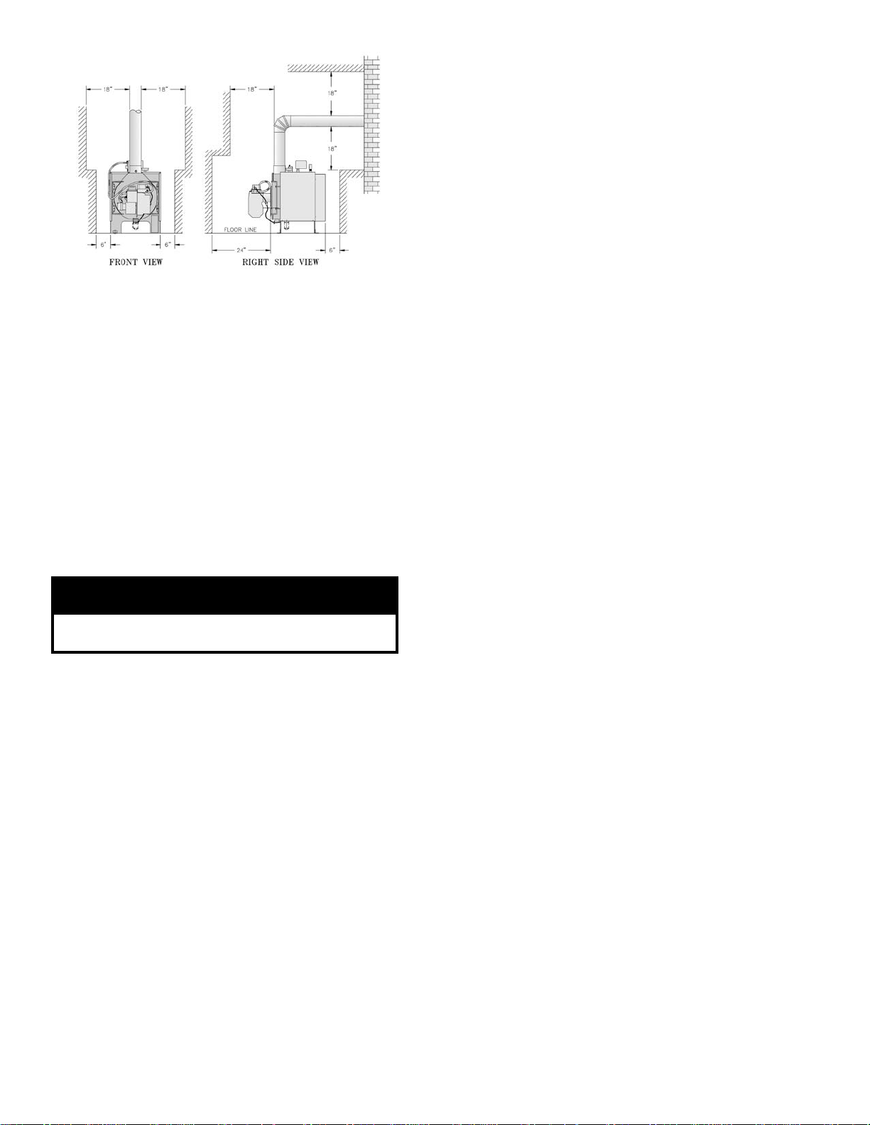
Figure 2: Minimum Installation Clearances To
Combustible Materials
NOTE 1: Listed clearances comply with American
National Standard ANSI/NFPA 31,
Installation of oil burning equipment.
NOTE 2: TES Series boilers can be installed in rooms
with clearances from combustible material as
listed above. Listed clearances can not be
reduced for alcove or closet installations.
NOTE 3: For reduced clearances to combustible
material, protection must be provided as
described in the above ANSI/NFPA 31
standard.
3. PROVIDE COMBUSTION AND VENTILATION
AIR. Local code provisions may apply and should be
referenced.
WARNING
Adequate combustion and ventilation air must be
provided to assure proper combustion.
A. Determine volume of space (boiler room). Rooms
communicating directly with the space in which the
appliances are installed, through openings not
furnished with doors, are considered a part of the
space.
Volume(ft
B. Determine total input of all appliances in the space.
Add inputs of all appliances in the space and round
the result to the nearest 1000 BTU per hour.
C. Determine type of space. Divide Volume by total
input of all appliances in space. If the result is
greater than or equal to 50 ft3/1000 BTU per hour,
then it is considered an unconned space. If the
result is less than 50 ft3/1000 BTU per hour then the
space is considered a conned space.
D. For boiler located in an unconned space of a
conventionally constructed building, the fresh air
3
) = Length(ft) x Width(ft) x Height(ft)
inltration through cracks around windows and
doors normally provides adequate air for combustion and ventilation.
E. For boiler located in a conned space or an uncon
ned space in a building of unusually tight con-
struction, provide outdoor air with the use of two
permanent openings which communicate directly or
by duct with the outdoors or spaces (crawl or attic)
freely communicating with the outdoors. Locate
one opening within 12 inches of top of space.
Locate remaining opening within 12 inches of
bottom of space. Minimum dimension of air
opening is 3 inches. Size each opening per
following:
Direct communication with outdoors.
(1)
Minimum free area of 1 square inch per 4,000
BTU per hour input of all equipment in space.
(2) Vertical ducts. Minimum free area of 1 square
inch per 4,000 BTU per hour input of all
equipment in space. Duct cross-sectional area
shall be same as opening free area.
(3) Horizontal ducts. Minimum free area of 1
square inch per 2,000 BTU per hour input of all
equipment in space. Duct cross-sectional area
shall be same as opening free area.
Alternate method for boiler located within
conned space. Use indoor air if two permanent openings communicate directly with
additional space(s) of sufcient volume such
that combined volume of all spaces meet
criteria for unconned space. Size each
opening for minimum free area of 1 square
inch per 1,000 BTU per hour input of all
equipment in spaces, but not less than 100
square inches.
F. Louvers and Grilles of Ventilation Ducts
(1) All outside openings should be screened and
louvered. Screens used should not be smaller
than 1/4 inch mesh. Louvers will prevent the
entrance of rain and snow.
(2) Free area requirements need to consider the
blocking effect of louvers, grilles, or screens
protecting the openings. If the free area of the
louver or grille is not known, assume wood
louvers have 20-25 percent free area and metal
louvers and grilles have 60-75 percent free
area.
(3) Louvers and grilles must be xed in the open
position, or interlocked with the equipment to
open automatically during equipment operation.
-
4
Page 5
II. Installation Instructions
1.
REMOVE CRATE
A. Remove all fasteners at crate skid.
B. Lift outside container and remove all other inside
fittings.
2.
REMOVAL OF BOILER FROM SKID
A. Tilt boiler, "walk" boiler backward, and set rear legs
down on oor. Tilt boiler backward, pull skid
forward and set front legs down on edge of skid.
Install close coupling, tee, and plug in return
coupling, see Step 7 and Figure 1. Point tee toward
permanent return location.
B. Tilt boiler backward and remove skid. Be careful not
to damage Burner and Jacket.
3.
CHANGE HINGE POSITION if necessary.
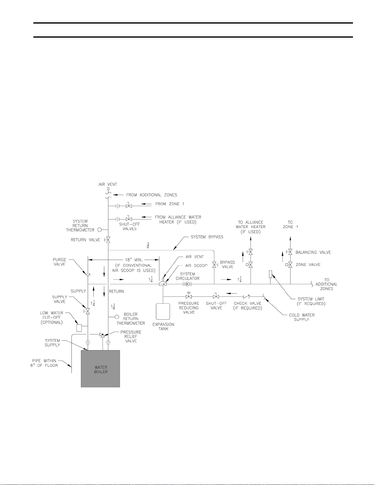
Figure 4: Recommended Water Piping for Zone Valve Zoned Heating Systems
5
Page 6

Figure 5: Recommended Water Piping for Circulator Zoned Heating Systems
6
Page 7

4.
INSTALL BOILER CONTROL.
A. Pull bulb and capillary tube out of hole in back of
control. Insert bulb in immersion well on top of
boiler and secure control with set screw in control.
B. Secure exible conduit to Jacket Wrapper side with
conduit clamp and sheet metal screw. Conduit must
be on same side of boiler as Swing Door hinges.
5.
MOVE BOILER TO PERMANENT POSITION by
sliding or walking.
6.
INSPECT FRONT AND REAR DOOR INSULATION
PIECES AND COMBUSTION CHAMBER LINER
A. OPEN SWING DOOR on front of boiler. Use
ashlight to inspect insulation pieces secured to
front and rear doors. Inspect Ceramic Fiber Blanket
secured to bottom of combustion chamber with
water glass adhesive. Replace any damaged pieces.
7.
CONNECT SUPPLY AND RETURN PIPING TO
HEATING SYSTEM
A. Hot water pipes shall have clearances of at least ½”
from all combustible construction.
B. Use a system by-pass if the boiler is to be operated
in a system which has a large volume or excessive
radiation where low boiler water temperatures may
be encountered (i.e. converted gravity circulation
system, etc.).
Valves should be located in the by-pass and return
line as illustrated in Figures 4 and 5 in order to
regulate water ow for maintenance of higher
boiler water temperature.
Set the by-pass and return valves to a half throttle
position to start. Operate boiler until the system
water temperature reaches its normal operating
range.
Adjust the valves to maintain 75°C to 85°C boiler
water temperature and greater than 45°C return
temperature. Adjust both valves simultaneously.
Closing the boiler return valve while opening the
by-pass valve will raise the boiler return temperature. Opening the boiler return valve while closing
the by-pass valve will lower the boiler return
temperature.
C. If this boiler is used in connection with refrigeration
systems, the boiler must be installed so that the
chilled medium is piped in parallel with the heating
boiler using appropriate valves to prevent the
chilled medium from entering the boiler, see Figure
6. Also consult I=B=R Installation and Piping
Guides.
D. If this boiler is connected to heating coils located in
air handling units where they may be exposed to
refrigerated air the boiler piping must be equipped
with ow control valves to prevent gravity circulation of boiler water during the operation of the
cooling system.
Figure 6: Recommended Piping for
Combination Heating & Cooling
(Refrigeration) Systems
E. A hot water boiler installed above radiation level
must be provided with a low water cutoff device as
part of the installation.
If a low water cut-off is required, it must be mount-
ed in the system piping above the boiler.
The minimum safe water level of a hot water boiler
is just above the highest water containing cavity of
the boiler; that is, a hot water boiler must be full of
water to operate safely.
F. There are many possible causes of oxygen contami-
nation such as:
(1) Addition of excessive make-up water as a
result of system leaks.
(2) Absorption through open tanks and ttings.
(3) Oxygen permeable materials in the distribution
system.
In order to insure long product life, oxygen sources
should be eliminated. This can be accomplished by
taking the following measures:
(1) Repairing system leaks to eliminate the need
for addition of make-up water.
(2) Eliminating open tanks from the system.
(3) Eliminating and/or repairing ttings which
allow oxygen absorption.
(4) Use of non-permeable materials in the distribu-
tion system.
(5) Isolating the boiler from the system water by
installing a heat exchanger.
CAUTION
Oxygen contamination of boiler water will cause
corrosion of iron and steel boiler components,
and can lead to boiler failure. TES Standard
Warranty does not cover problems caused by
oxygen contamination of boiler water.
7
Page 8

8.
INSTALL SMOKEPIPE — The TES boiler should be vented
into a reclay tile-lined masonry chimney or a chimney
constructed from Type L Vent or a factory built
chimney that complies with the Type HT requirement,
of UL103. The chimney and vent pipe shall have a
sufcient draft at all times, to assure safe proper
operation of the boiler. See Figure 7 for recommended
installation.
a home without insulation or storm windows. With
increasing fuel prices that home probably has been
insulated and tted with storm windows so that the
heat loss of the home has been reduced. This
requires less fuel to be burned and sends less heat
up the chimney.
A new boiler probably has a higher efciency than
the boiler being replaced. That probably means that
the stack temperature from the new boiler will be
lower than that from the old boiler and with less
room air being drawn up the chimney to dilute the
stack gases. The combination of a large uninsulated
chimney, reduced ring rate, reduced ring time,
lower stack temperature and less dilution air can, in
some cases, contribute to the condensing of small
amounts of water vapor in the chimney. Such
condensation, when it occurs, can cause chimney
deterioration. In extreme cases, condensed water
may be visible on the outside of the breeching or
chimney. In those extreme cases, the chimney may
have to be lined to insulate the chimney and thus
prevent the condensation. The addition of dilution
air into the chimney may assist in drying the
chimney interior surfaces.
C. Heat extractors mounted into the breeching are not
recommended.
Figure 7
A. Install the draft regulator following the instructions
furnished with the regulator. See Figure 8 for
alternate draft regulator locations.
Figure 8
B. Consider the chimney overall. Chimneys that have a
high heat loss may become less suitable as the heat
loss of the home goes down and the efciency of
the boiler installed goes up. Most homes have a
chimney appropriate for the fuel and the era in
which the home was built. That may have been a
coal red or an inefcient oil red boiler built into
9.
INSTALL ELECTRIC WIRING
A. Follow the National Electrical Code and local
regulations. A separate electrical circuit must be run
from the main electrical service with an overcurrent device/disconnect in the circuit. A service
switch is recommended and may be required by
some local jurisdictions. Wiring should conform to
Figures 11A, 11B and 11C.
B. CANADA — Refer to CSA standard C22.2 Part 1,
1990, Electrical Features of Fuel Burning Equipment (Gas and Oil).
C. If boiler is installed in Canada, a blocked vent safety
switch must be installed. Refer to Blocked Vent
Safety Switch Instruction Supplement provided
with boiler (Canada only).
10.
FUEL UNITS AND OIL LINES
Use exible oil line(s) so that Swing Door can be
opened without disconnecting oil supply.
A supply line fuel oil lter is recommended as a
minimum for all ring rates but a pleated paper fuel oil
lter is recommended for the lowest (.6 GPH) ring
rate application to prevent nozzle fouling.
SINGLE-PIPE OIL LINES — Standard burners are
provided with single-stage 3450 rpm fuel units with the
by-pass plug removed for single-pipe installations.
The single-stage fuel unit may be installed single-pipe
with gravity feed or lift. Maximum allowable lift is 8
feet. See Figure 9.
8
Page 9

Figure 9
IMPORTANT
Single-pipe installations must be absolutely airtight
or leaks or loss of prime may result. Bleed line and
fuel unit completely.
TWO-PIPE OIL LINES - For two-pipe systems where
more lift is required, the two-stage fuel unit is
recommended. Tables 2 (single-stage) and 3 (two-stage)
show allowable lift and lengths of 3/8-inch and ½-inch
OD tubing for both suction and return lines. Refer to
Figure 10.
TABLE 2: SINGLE-STAGE UNITS (3450 RPM)
TWO-PIPE SYSTEMS
Maximum Length of Tubing
"H" + "R"
Lift "H"
3/8" OD
Tubing (3 GPH)
0' 84' 100'
1' 78' 100'
2' 73' 100'
3' 68' 100'
4' 63' 100'
5' 57' 100'
6' 52' 100'
7' 47' 100'
8' 42' 100'
9' 36' 100'
10' 31' 100'
11' 26' 100'
12' 21' 83'
13' --- 62'
14' --- 41'
1/2" OD
Tubing (3 GPH)
Figure 10
Be sure that all oil line connections are absolutely
airtight.
Check all connections and joints. Flared ttings are
recommended. Do not use compression ttings.
Open the air-bleed valve and start the burner. For clean
bleed, slip a 3/16” ID hose over the end of the bleed
valve and bleed into a container. Continue to bleed for
15 seconds after oil is free of air bubbles. Stop burner
and close valve.
TABLE 3: TWO-STAGE UNITS (3450 RPM)
TWO-PIPE SYSTEMS
Maximum Length of Tubing
"H" + "R"
Lift "H"
0' 93' 100'
2' 85' 100'
4' 77' 100'
6' 69' 100'
8' 60' 100'
10' 52' 100'
12' 44' 100'
14' 36' 100'
16' 27' 100'
18' --- 76'
3/8" OD
Tubing (3 GPH)
1/2" OD
Tubing (3 GPH)
9
Page 10

Wiring Diagram for TES Boiler Control Panel
10
Page 11

III. Operating and Service Instructions
WARNING
All boilers equipped with burner swing door have a potential hazard which can cause severe property damage,
personal injury or loss of life if ignored. Before opening swing door, turn off service switch to boiler and
disconnect two halves of Burner Swing Door Interlock wiring harness to prevent accidental ring of burner
outside the combustion chamber. Be sure to tighten swing door fastener completely and reconnect two
halves of Burner Swing Door Interlock when service is completed.
1.
ALWAYS INSPECT INSTALLATION BEFORE
STARTING BURNER.
2.
FILL HEATING SYSTEM WITH WATER.
NOTE: It is important to properly remove the oil and
dirt from the system.
CLEAN HEATING SYSTEM If boiler water is dirty,
refer to step 13 for proper cleaning instructions.
A. Fill entire Heating System with water and vent air
from system.
3.
CHECK CONTROLS, WIRING AND BURNER to be
sure that all connections are tight and burner is rigid,
that all electrical connections have been completed and
fuses installed, and that oil tank is lled and oil lines
have been tested.
4.
LUBRICATION — Follow instruction on burner and
circulator label to lubricate, if oil lubricated. Most
motors currently used on residential type burners
employ permanently lubricated bearings and thus do
not require any eld lubrication. Water lubricated
circulators do not need eld lubrication.
Do not over-lubricate. This can cause as much trouble as no
lubrication at all.
5.
ADJUST CONTROLS SETTINGS with burner service
switch turned “ON”.
11
Page 12

Important Product Safety Information
Refractory Ceramic Fiber Product
Warning:
The Repair Parts list designates parts that contain refractory ceramic fibers
(RCF). RCF has been classified as a possible human carcinogen. When
exposed to temperatures about 985°C, such as during direct flame contact,
RCF changes into crystalline silica, a known carcinogen. When disturbed as a
result of servicing or repair, these substances become airborne and, if inhaled,
may be hazardous to your health.
AVOID Breathing Fiber Particulates and Dust
Precautionary Measures:
Do not remove or replace RCF parts or attempt any service or repair work
involving RCF without wearing the following protective gear:
1. A National Institute for Occupational Safety and Health (NIOSH)
approved respirator
2. Long sleeved, loose fitting clothing
3. Gloves
4. Eye Protection
• Take steps to assure adequate ventilation.
• Wash all exposed body areas gently with soap and water after contact.
• Wash work clothes separately from other laundry and rinse washing
machine after use to avoid contaminating other clothes.
• Discard used RCF components by sealing in an airtight plastic bag. RCF
and crystalline silica are not classified as hazardous wastes in the United
States and Canada.
First Aid Procedures
• If contact with eyes: Flush with water for at least 15 minutes. Seek
immediate medical attention if irritation persists.
• If contact with skin: Wash affected area gently with soap and water.
Seek immediate medical attention if irritation persists.
• If breathing difficulty develops: Leave the area and move to a location
with clean fresh air. Seek immediate medical attention if breathing
difficulties persist.
• Ingestion: Do not induce vomiting. Drink plenty of water. Seek
immediate medical attention.
:
12
Page 13

There are various test kits available to trace air
leaks, such as electronic sight glasses. Follow the
manufacturers' instructions to nd air leaks.
The following actions can eliminate air leaks:
(1) Bleed pump as detailed previously.
(2) Replace are ttings.
(3) Replace oil supply line.
(4) Repair oil lter leaks.
(5) Replace or repair tank ttings.
NOTICE
CHECK TEST PROCEDURE. A very good test for
isolating fuel side problems is to disconnect the
fuel system and with a 2' length of tubing, re
out of an auxiliary ve gallon pail of clean, fresh,
warm #2 oil from another source. If the burner runs
successfully when drawing out of the auxiliary
pail then the problem is isolated to the fuel or fuel
lines being used on the jobsite.
E. GASKET LEAKS — If 11.5 to 12.5% CO
#1 smoke or less cannot be obtained in the
breeching, look for air leaks around the ue collar.
Such air leaks will cause a lower CO2 reading in the
breeching. The smaller the ring rate the greater
effect an air leak can have on CO2 readings.
F. DIRT — A fuel lter is a good investment. Acci-
dental accumulation of dirt in the fuel system can
clog the nozzle or nozzle strainer and produce a
poor spray pattern from the nozzle. The smaller the
ring rate, the smaller the slots become in the
nozzle and the more prone to plugging it becomes
with the same amount of dirt.
G. WATER — Water in the fuel in large amounts will
stall the fuel pump. Water in the fuel in smaller
amounts will cause excessive wear on the pump,
but more importantly water doesn’t burn. It chills
the ame and causes smoke and unburned fuel to
pass out of the combustion chamber and clog the
ueways of the boiler.
with a
2
H. COLD OIL — If the oil temperature approaching
the fuel pump is 5°C or lower poor combustion or
delayed ignition may result. Cold oil is harder to
atomize at the nozzle. Thus, the spray droplets get
larger and the ame shape gets longer. An outside
fuel tank that is above grade or has fuel lines in a
shallow bury is a good candidate for cold oil. The
best solution is to bury the tank and lines deep
enough to keep the oil above 5°C.
I. HIGH ALTITUDE INSTALLATIONS
Air settings must be increased at higher altitudes.
Use instruments and set for 11.5 to 12.5% CO
J. START-UP NOISE — Late ignition is the cause of
start-up noises. If it occurs recheck for electrode
settings, ame shape, air or water in the fuel lines.
K. SHUT DOWN NOISE — If the ame runs out of air
before it runs out of fuel, an after burn with noise
may occur. That may be the result of a faulty cutoff valve in the fuel pump, or it may be air trapped
in the nozzle line. It may take several ring cycles
for that air to be fully vented through the nozzle.
Water in the fuel or poor ame shape can also cause
shut down noises.
. ATTENTION TO BOILER WHILE NOT IN
15
OPERATION.
A. Spray inside surfaces with light lubricating or
crankcase oil using gun with extended stem so as to
reach all corners.
B. Always keep the manual fuel supply valve shut off
if the burner is shut down for an extended period of
time.
C. To recondition the heating system in the fall season
after a prolonged shut down, follow the instructions
outlined in Section III — Operating and Service
Instructions, Items 1 through 8.
.
2
13
Page 14

IV. Boiler Cleaning
WARNING
All boiler cleaning must be completed with burner service switch turned off. Boilers equipped with burner
swing door have a potential hazard which can cause severe property damage, personal injury or loss of
life if ignored. Before opening swing door, turn off service switch to boiler to prevent accidental ring of
burner outside the combustion chamber. Be sure to tighten swing door fastener completely when service is
completed.
1.
CLEAN THE FIRETUBES
A. For access to reside of boiler, pull two halves of
Burner Swing Door Interlock wiring harness apart,
remove hex nuts holding door closed and open
swing door.
B. Prior to cleaning boiler, lay a protective cloth or
plastic over combustion chamber liner.
C. Using a 1 1/2" diameter wire brush (30" handle),
clean retubes. Measure 15" from end of brush
opposite handle, and mark handle. DO NOT allow
this mark to go past front end of retube during
cleaning, or brush will hit rear door insulation
piece.
2
. CLEAN THE COMBUSTION CHAMBER
Using wire or ber bristle brush, clean inside of
combustion chamber. DO NOT let brush hit rear door
insulation piece or combustion chamber liner.
3
. AFTER CLEANING
Vacuum debris inside bottom of rear door, remove
protective cloth, and vacuum remaining reside of
boiler as necessary. BE CAREFUL not to damage liner
or rear door insulation piece. Inspect front and rear door
insulation pieces, front door gaskets and combustion
chamber liner for damage. Replace any damaged
pieces.
. CLOSE BOILER
4
CAUTION: Do not start burner unless burner swing door is
securely closed. Close door, install hex nuts, and tighten
securely. Door should be parallel to tubesheet when
viewed from top and sides. Reconnect two halves of
Swing Door Interlock.
WARNING
The boiler must be connected to an approved
chimney in good condition. Serious property
damage could result if the boiler is connected
to a dirty or inadequate chimney. The interior of
the chimney ue must be inspected and cleaned
before the start of the heating season and
should be inspected periodically throughout the
heating season for any obstructions. A clean and
unobstructed chimney ue is necessary to allow
noxious fumes that could cause injury or loss
of life to vent safely and will contribute toward
maintaining the boiler's efciency.
14
Page 15

SERVICE RECORD
DATE SERVICE PERFORMED
5
1
 Loading...