

Page 1
1
LMANMB120LP
Copyright Tes Drying Systems, 2014
REVISED: 01/29/2015
Page 2
2
Table of Contents
LMANMB120LP
Introduction 3
General Information 4
Warranty 6
SECTION 1
Heater Operation Safety 7
Warning Labels 9
SECTION 2
Menu Navigation 10
Air Flow Set-up 13
Remote Probe Set-up 14
Remote Fan Control 17
Dual Circuit Indicator 18
Software Updates 19
Data Charting 20
SECTION 3
Heater Operation 23
Troubleshooting 29
Re-initializing Memory 33
Resetting Processor 35
Wiring Diagrams 36
Revised: 11/09/12
SECTION 4
Maintenance 40
Parts 41
SECTION 5
Drying Carpet 50
Drying Wood Floors 52
Drying Walls 54
Copyright Tes Drying Systems, 2014
Page 3

3
Introduction
Congratulations on your purchase of the Tes Drying Systems E-TES SD 120 Volt
Low Profile Electric Thermal Energy System. This manual is a guide for safe
operation and maintenance of this unit.
Read and understand this manual completely before operating this unit.
The temperature controls of the E-TES SD 120 Volt Low Profile Electric
Thermal Exchange unit are designed for safe operation in a variety of drying
operations. If setup improperly the E-TES SD can raise the room temperature to
140°F with an output temperature up to 210°F before it shuts off. Proper setup
and use of the temperature controls is required to protect the structure and
contents.
Improper operation, alteration, service or
maintenance can cause property damage, personal injury or loss of life.
Service must be performed by a qualified technician, service agency or electrician.
Tes Drying Systems is in no way responsible and is excluded from liability in
respect to any loss or damage which may arise due to improper operation,
maintenance or repair.
This manual should be maintained in legible condition adjacent to the unit or in a
secure location for future reference.
Any questions pertaining to the operating or servicing of this unit should be
directed to your nearest Tes Drying Systems distributor.
This manual is written specifically for the E-TES SD 120 Volt Low Profile
Electric Thermal Exchange units manufactured by:
Tes Drying Systems
4282 S 590 W
Salt Lake City, UT 84123
801-261-1282
Information in this manual is subject to change without notice and does not
represent a commitment on the part of Tes Drying Systems.
Copyright Tes Drying Systems, 2014
Page 4
4
General Information
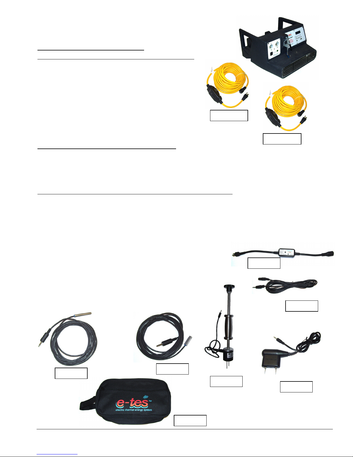
PGE5060
AT206
AT204
AT208
NM4407
A
AT200
AC102
NM4407
A
AT202
E-TES SD 120 Volt Low Profile
ELECTRIC THERMAL ENERGY SYSTEM
10,000 Btu 120vac Electric Model
Height: 13.5”
Length: 26.5”
Width: 22.75”
Weight: 30 lbs.
Heater watt rating: 3000 watts
Cord 1 Amp Draw: 12amps
Cord 2 Amp Draw: 12amps
E-TES SD 120 Volt Standard Equipment
ELECTRIC THERMAL EXCHANGE UNIT
NM4407A (2) 50’ - 12/3 GFCI Power Cords w/ 5-15P& 5-15R ends
SMART E-TES SD 120 Volt Optional Sensors & Controls
ST001 E-TES Charter Software (Available free online at tesdryingsystem.com)
AT210 E-TES SD Smart Package
Smart Package includes:
(1) AT200, (1) AT202, (1) PGE5060, (2) AT204, (1) AT206 & (1) AT208
AT200 Surface Temperature Sensor w/ 10ft cord
AT202 Air Temperature Sensor w/ 10ft cord
PGE5060 Moisture Level Sensor w/ 4ft cord
AT204 10 ft. sensor extension cord M-F jack & plug
AT206 Remote Exhaust Controller
AT208 Travel Bag for Sensor Storage
AC102 Hammer Probe w/ 4ft cord
Copyright Tes Drying Systems, 2014
Page 5
5
Additional / Optional Equipment
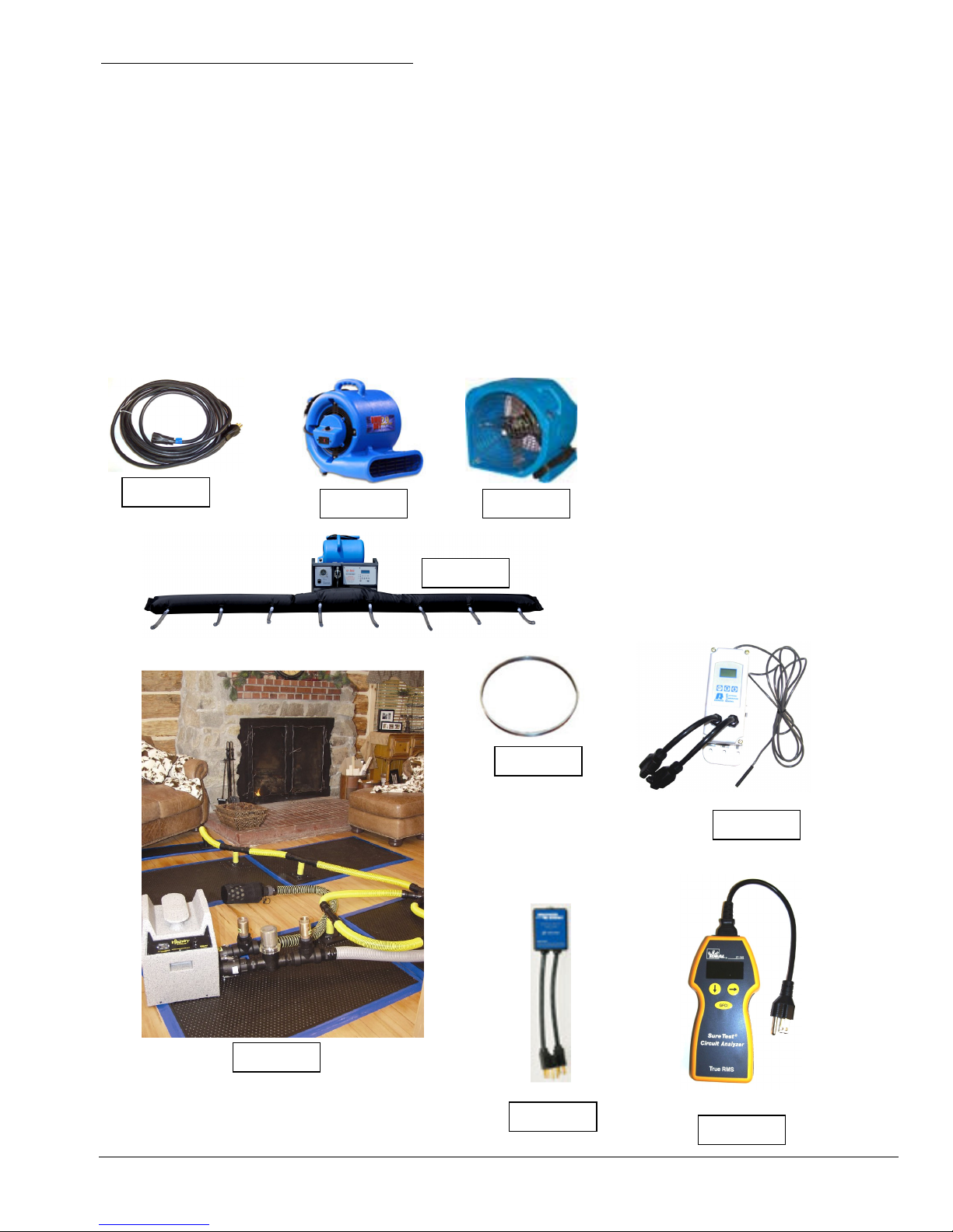
AX33
AC25A
MB230
AC514
AX68
AC128
AC246
MI22
AT56
PGE500 Replacement Needles for Moisture Probe (Package of 20)
PGE0501 Replacement Retaining Nuts for Moisture Probe (Package of 2)
AX33 50’ - 12/3 Extension Cord w/ 5-15P & 5-15R
AC262A Lay Flat Ducting 14” Dia. (22.5” flat) x 500’
AT56 Duct Ring 14”
AC25A Omni Dry 2.9 Centrifugal Air Mover
AC246 OmniDry Focal Point Axial Air Mover
AC128 SureTest Circuit Analyzer
AX68 Breaker Buddy II
MB230 Single Stage Exhaust Controller
AC514 Flexi Dry Wall Drying System
MI22 Injectidry HP60FDP Floor Drying Package
Copyright Tes Drying Systems, 2014
Page 6

6
Warranty
Your E-TES SD 120 Volt Low Profile Electric Thermal Exchanger is designed to give you years of reliable service.
If a problem should arise use the troubleshooting section in the operation manual to diagnose and correct the
problem if possible. If you are unable to determine the cause or solution to the problem contact your distributor or
Tes Drying Systems for assistance.
Tes Drying Systems warrants the roto-molded body of the E-TES SD 120 Volt Low Profile Electric Thermal
Exchanger to be free from defects in material or workmanship for five years from the date of purchase.
Warranty coverage does not include damage to body due to overheating after the first year.
All other components of the E-TES SD 120 Volt Low Profile Electric Thermal Exchanger are warranted to
be free of defects in material and workmanship for one year from the date of purchase.
During the warranty period, Tes Drying Systems will, at its option repair or replace components which
prove to be defective.
• This warranty does not provide for replacement of complete units due to defective components.
• Service Labor is only covered for the first 90 days after the date of purchase.
• Any costs for transportation are not covered in this warranty.
• Replacement parts are warranted only for the remainder of the original warranty period.
This warranty shall not apply to defects resulting from improper operation, lack of maintenance,
condensation, chemical corrosion, unauthorized modification, misuse or abuse.
This warranty does not cover normal wear to items such power cords, plug adapters or other items which
require replacement as a result of ordinary usage.
To obtain warranty service for the E-TES SD 120 Volt Low Profile Electric Thermal Exchanger, contact
your distributor or Tes Drying Systems. If the unit must be returned to Tes Drying Systems or an
authorized service center, the purchaser shall prepay shipping charges for products returned for warranty
service.
• No returned items will be accepted by Tes Drying Systems without prior authorization. All returns must
have a return authorization number, issued by Tes Drying Systems, clearly marked on the exterior of the
package.
Tes Drying Systems makes no other warranty either expressed or implied with respect to this product.
The remedies provided herein are the purchaser’s sole and exclusive remedies.
In no event shall Tes Drying Systems be liable for any direct, indirect, special, incidental or consequential
damages.
This warranty gives you specific legal rights. You may also have other rights which vary from jurisdiction
to jurisdiction.
Copyright Tes Drying Systems, 2014
Page 7
7
Section
1
Heater Operation Safety
When using electrical appliances, basic precautions should always be
followed to reduce the risk of fire, electric shock, and injury to persons, including the following:
• Read all instructions before using this heater. Use this heater only as described in this manual.
Any other use not recommended by the manufacturer may cause fire, electric shock, or injury to
persons.
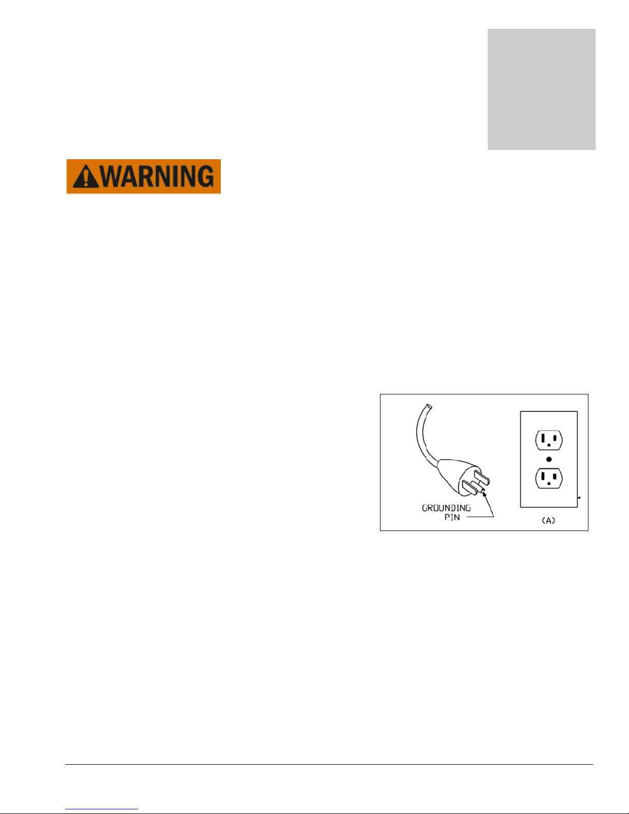
• This machine shall be grounded while in use to protect the operator from electric shock. The machine is
provided with two three-conductor cords with three-contact grounding type attachment plugs to fit the
proper grounding type receptacles. The green (or green and yellow) conductor in the cord is the
grounding wire. Never connect this wire to other than the grounding pin of the attachment plug.
• Connect to properly grounded outlets only. The 120volt power source must be wired and have 15 or 20
amp circuit breaker to safely handle the rated amperage of the unit. Examine the electric outlet before
connecting your E-TES SD. A Loose fitting or damaged outlet can cause the power cord to overheat. Do
not use a loose fitting or damaged outlet. If necessary, have an electrician repair the outlet before
connecting your E-TES SD to prevent cord or outlet
damage.
• This machine is for use on two separate nominal 120-volt
15 amp circuits and the power cords have grounding plugs
that resembles the plug illustrated in the sketch shown to
the right. Make sure that the machine is connected to an
outlet having the same configuration as the plug. No
adapter should be used with this machine.
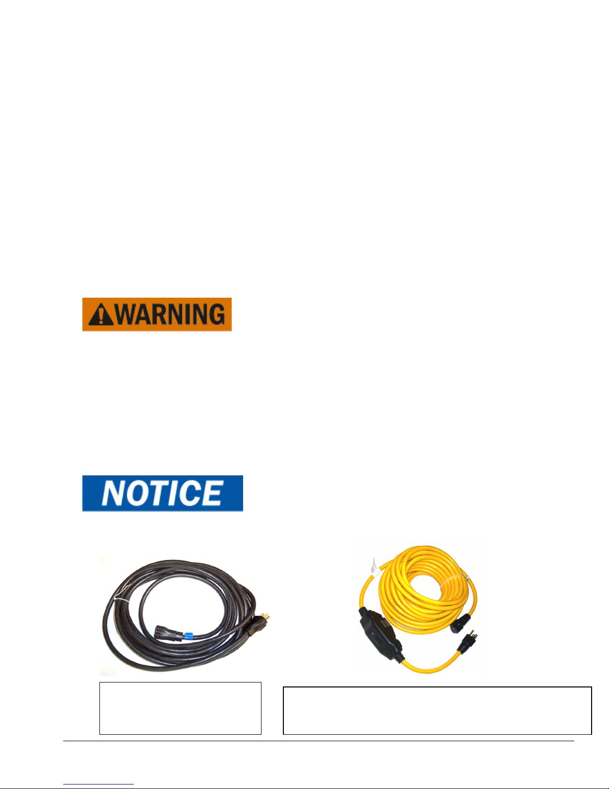
• Use no more than one 50 ft. 12 gauge extension cord
(100’ total cord length) per circuit when operating this
heater. Any extension cord used with this heater must be
12 gauge or 10 gauge three-conductor cords with three-contact grounding type attachment plugs to fit the
proper grounding type receptacles.
• The Ground Fault Circuit Interrupting (GFCI) protected cords supplied with the E-TES SD provide additional
safety when operating the E-TES SD on wet surfaces. Keep cord connections off wet floors. Protect cord
connections from damp surfaces and water sources. Always use the GFCI cords to reduce the risk of electrical
shock. Test operation of GFCI before each use. (See Page 40) Do not use outdoors. Do not use in standing
water.
• Do not run cord under carpeting. Do not cover cord with throw rugs, runners, or similar coverings. Do
not route cord under furniture or appliances. Arrange cord away from traffic area and where it will not be
tripped over.
• Do not operate any heater with a damaged cord or plug or after the heater malfunctions, has been
dropped or damaged in any manner. Discard damaged cord or heater, or return to authorized service
facility for examination and/or repair.
Copyright Tes Drying Systems, 2014
Page 8
8
• This heater is hot when in use. To avoid burns, do not let bare skin touch hot surfaces. Use handles when
NEMA 5
-
15P & 5
-
15R ends
moving this heater. Keep combustible materials, such as furniture, pillows, bedding, papers, clothes, and
curtains at least 3 feet (0.9 m) from the front of the heater and keep them away from the sides and rear.
• Do not operate this heater unless all panels and guards are in place and properly secured.
• Extreme caution is necessary when any heater is used by or near children or invalids and whenever the
heater is left operating and unattended.
• Always unplug the heater when not in use. To unplug the heater, turn E-TES SD switch to off, then
remove plugs from outlets.
• Unplug machine power cords from outlets & then disconnect cords from the E-TES SD before performing
any repair on the heater.
• This heater is not intended for use in bathrooms, laundry areas and similar indoor locations. Never locate
heater where it may fall into a bathtub or other water container.
• Do not insert or allow foreign objects to enter any ventilation or exhaust opening as this may cause an
electric shock or fire, or damage the heater.
• To prevent a possible fire, do not block air intakes or exhaust in any manner. Do not use on soft surfaces,
like a bed, where openings may become blocked.
• A heater has hot and arcing or sparking parts inside. Do not use it in areas where gasoline, paint, or
flammable liquids are used or stored.
•
Always turn Heater OFF and keep air mover running for 5 minutes to
cool heater before turning air mover OFF. If air flow is turned off and the unit is not cooled properly the
heater box and front grill may get very hot, creating a burn hazard or damaging the unit.
• Restriction of the air flow from the heater snout may cause E-TES SD to overheat and shutoff.
• Adequate air flow must be maintained across heating elements for proper, safe operation. Do not disable
airflow sensor or other safety switches, doing so may result in damage to heater and will void warranty.
• Do not direct the outlet air flow towards objects which may be damaged by heat.
• Remove Feet or carpet clamps from snout of air mover before placing air mover into E-TES SD Electric
Thermal Exchanger to prevent damage to air seal gasket.
•
Always use Remote Temperature Sensors, Remote Power
Controllers or other form of temperature control to keep room temperature below 105ºF
during the drying process.
AX33
12/3 X 50’ Extension Cord
NEMA 5-15P & 5-15R ends
Copyright Tes Drying Systems, 2014
NM4407A
12/3 X 50’ GFCI Protected Extension Cord – Auto Re-set
Page 9
9
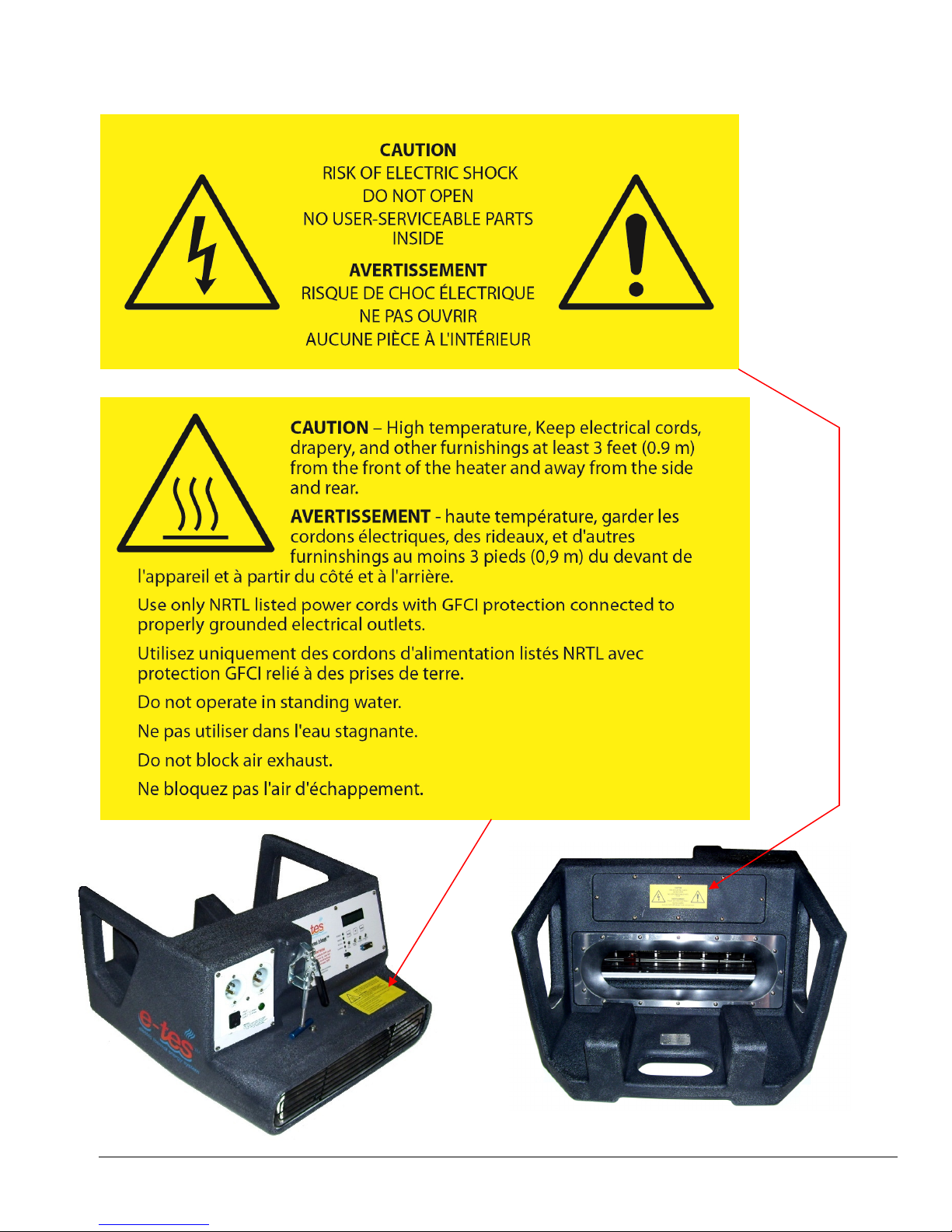
WARNING LABELS
Copyright Tes Drying Systems, 2014
Page 10
Navigation – Remote Sensor Set-up & Data
Section
2
Charting
E-TES SD MENU NAVIGATION:
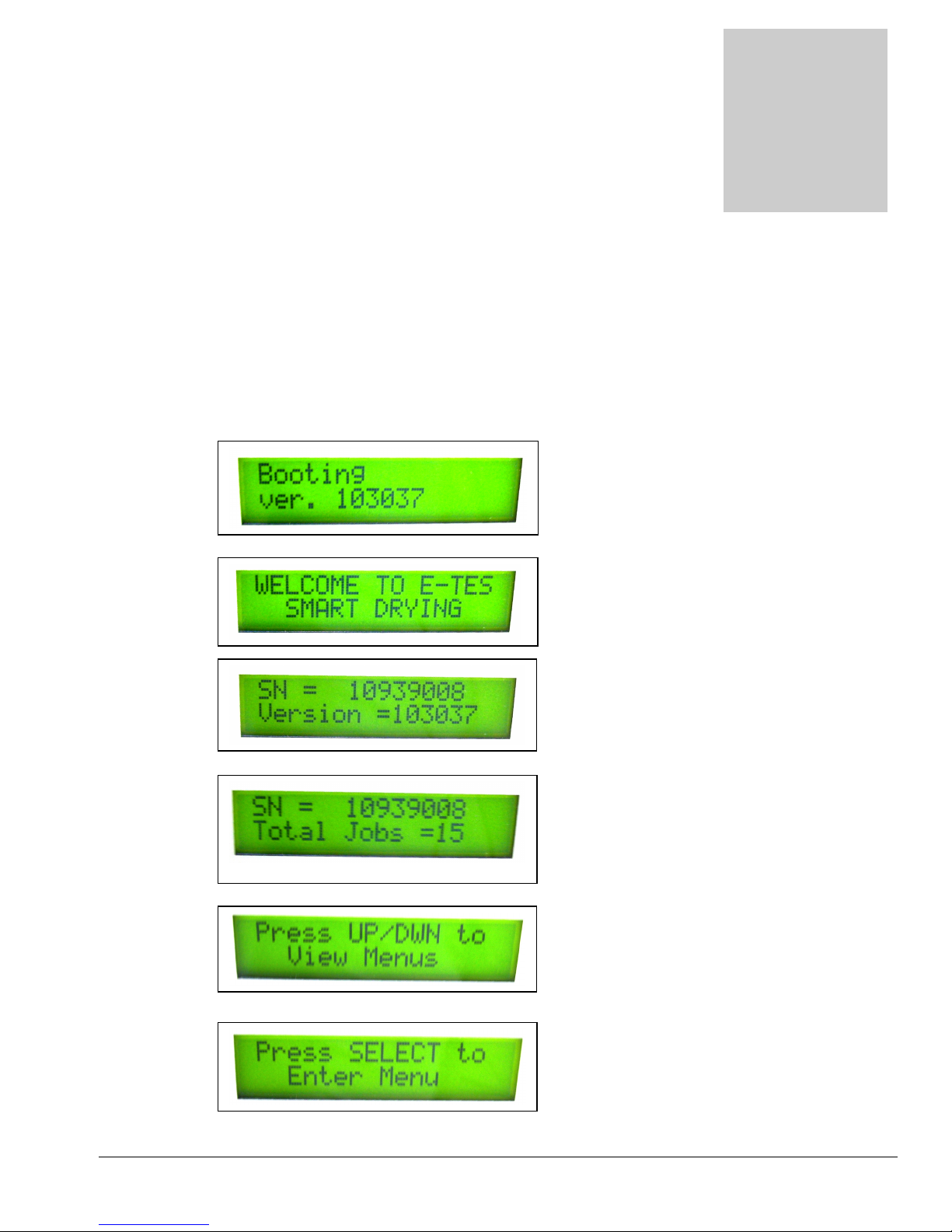
With the GFCI reset and the power cord connected to the E-TES SD, turn power switch to the ON position.
Display will quickly scroll through the first six screens, before stopping at the Main Screen.
First screen:
Second screen:
Third screen:
Fourth screen:
Fifth screen:
Sixth screen:
Copyright Tes Drying Systems, 2014
10
Booting Screen
Software version booting up
Welcome Screen
Unit serial number and
software version
Unit serial number and
number of jobs logged
Directions for how to view
menus
Directions for how to enter
menus to change settings
Page 11
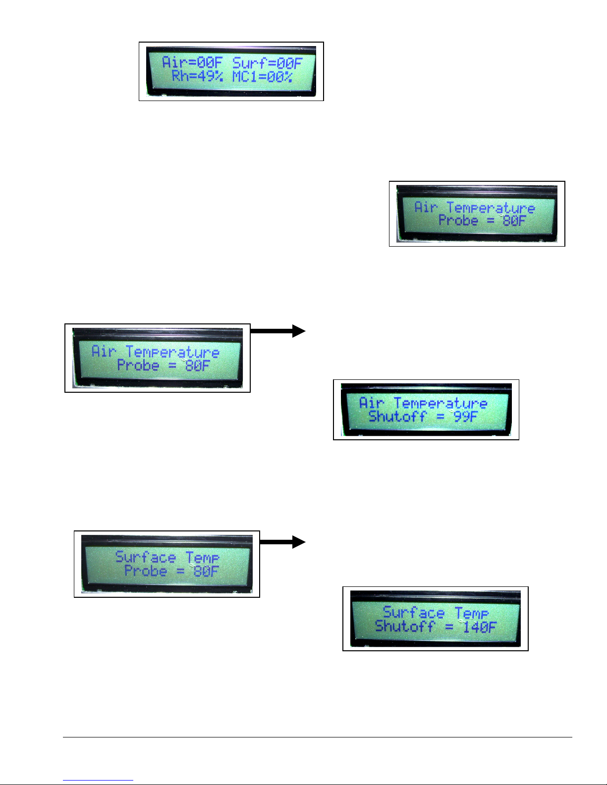
MAIN SCREEN:
Main screen will display current probe
temperatures or default settings if no probes are
connected.
• Air Default Setting: 00F
• Surface Default Setting: 00F
• Moisture 1 Default Setting: 00%
• Rh (Relative Humidity): Current value
Press UP / DOWN to move from Main Screen and scroll through Menu
From the Main Screen
PRESS DOWN: TO ACCESS AIR TEMPERATURE SCREEN
OR
PRESS UP: TO CURRENT DATE & TIME SCREEN
Air Temperature Screen: This tells you the current reading of the Air Temperature Sensor
probe if it is connected to the E-TES SD or the default value of 00F if the probe is not
connected.
• Press DOWN to move to Surface Temp Screen
• Press UP to return to Main Screen
Surface Temperature Screen: This tells you the current reading of the Surface Temperature
Sensor probe if it is connected to the E-TES SD or the default value of 00F if the probe is
not connected.
• Press DOWN to move to Moisture 1 Value Screen
• Press UP to return to Air Temperature Screen
Press SELECT to set Air Temperature Probe
shutdown temperature. Use UP/DOWN to
change Air Temperature shutoff setting.
Press SELECT to set Surface Temperature
Probe shutdown temperature. Use UP/DOWN
to change Surface Temperature shutoff setting.
Copyright Tes Drying Systems, 2014
11
Page 12
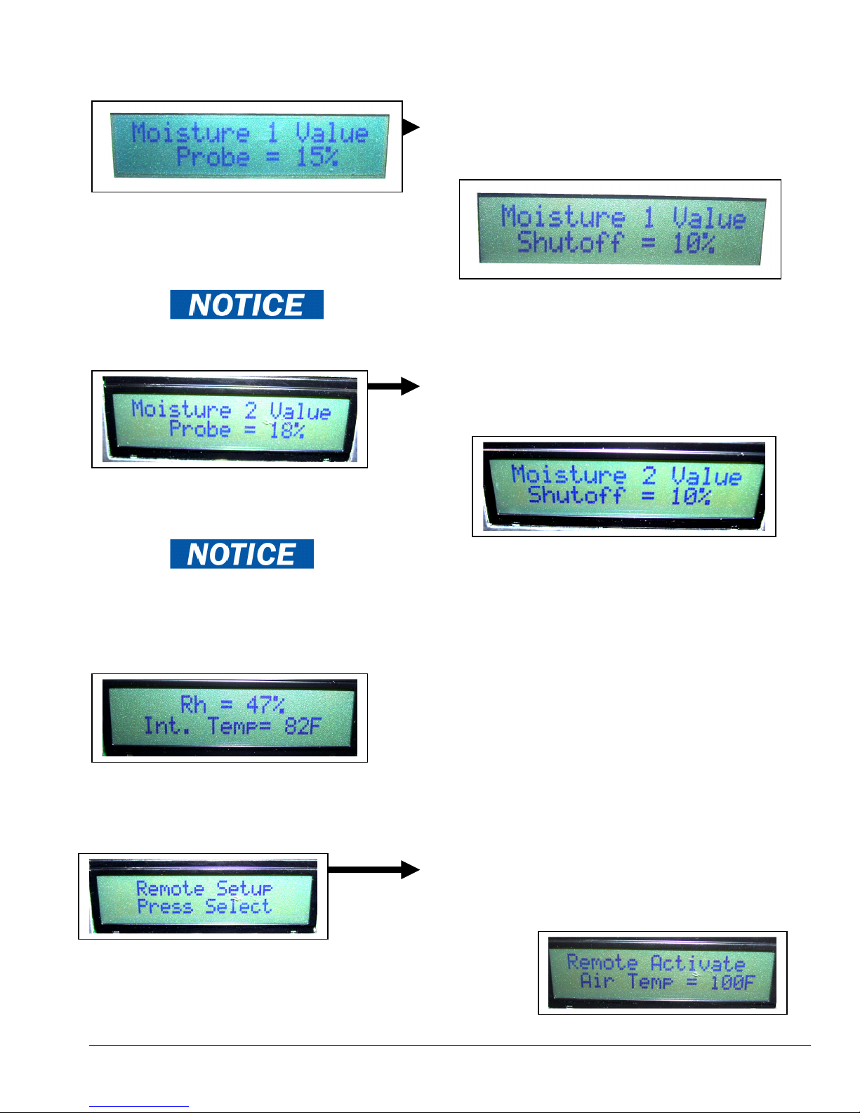
Moisture 1 Value Screen: This tells you the current reading of the Moisture probe if it is
• Press
UP to return to Humidity Internal Temperature Screen
connected to the E-TES SD or the default value of 00% if the probe is not connected.
• Press DOWN to move to Moisture 2 Value Screen
• Press UP to return to Surface Temp Screen
Press SELECT to set Moisture Probe shutdown
percentage. Use UP/DOWN to change moisture
percentage level set point.
Moisture 2 Value Screen: This tells you the current reading of the Moisture probe if it is
connected to the E-TES SD or the default value of 00% if the probe is not connected.
• Press UP to return to Moisture 1 Value Screen
• Press DOWN to move to Humidity / Internal Temperature
Screen
Press SELECT to set Moisture Probe shutdown
percentage. Use UP/DOWN to change moisture
percentage level set point.
Humidity / Internal Temperature Screen: This tells you the relative humidity percentage
and temperature inside the E-TES SD box.
• Press DOWN to move to Remote Setup screen
• Press UP to return to Moisture 2 Value screen
Remote Setup Screen: This allows you to set temperature at which the E-TES SD will turn
on Remote Exhaust Controller. (Remote Air Temperature Sensor to operate remote control.)
• Press DOWN to move to Air Flow Setup Screen
Press SELECT to set the E-TES Remote Exhaust
Controller turn on temperature. Use UP/DOWN to
change temperature.
Copyright Tes Drying Systems, 2014
12
Page 13
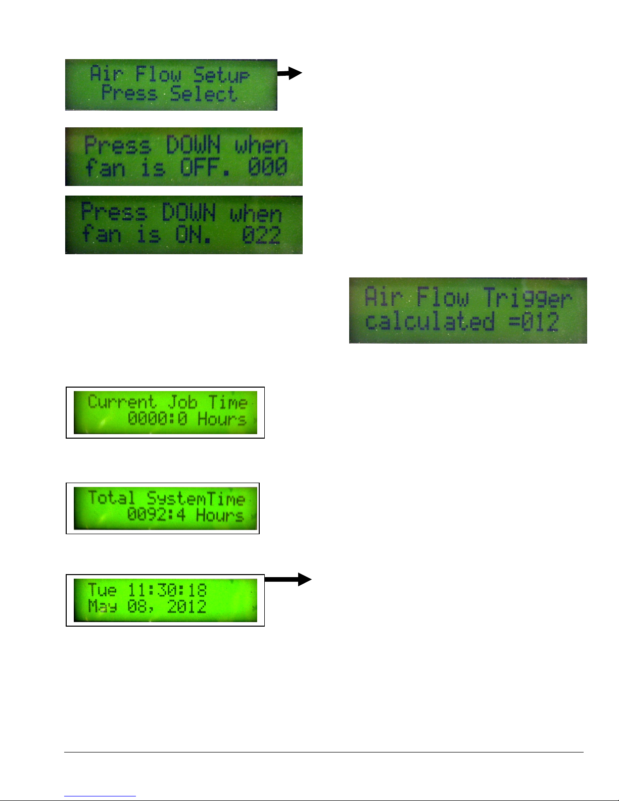
Air Flow Setup Screen: This allows you to recalibrate the Air Pressure Sensor to maintain
DAY NUMBER or YEAR.)
proper air pressure sensor function for reliable heater operation.
• Press DOWN to move to the Current Job Time Screen.
• Press UP to return to the Remote Setup Screen
Press SELECT to set the Air Pressure Sensor trigger point.
Follow the screen directions using the DOWN button to set
the levels with the air mover OFF & ON.
1. First turn the air mover OFF. When the fan is off and
the number stops changing, press DOWN.
This is the Off Set Point.
(Shown as 000 in this example)
2. Then turn the air mover ON at low speed. Press
DOWN as soon as the fan on number is about 15-25
points higher than the Off Set Point. This is the ON
Set Point. (Shown as 022 in this example)
3. The Air Flow Trigger point is now set. The Air Flow
Trigger is approximately half way between the Off Set
Point and the On Set Point.
(Shown as 012 in this example)
Current Job Time Screen: This shows the time the system has run since the switch was last
turned on.
• Press DOWN to move to Total System Time Screen
• Press UP to return to Air Flow Setup Screen
Total System Time Screen: This shows the total time the system has been run on all jobs.
• Press DOWN to move to Date & Time Screen
• Press UP to return to Current Job Time Screen
Current Date and Time Screen
• Press DOWN to return to Main Screen
• Press UP to return to Total System Time Screen
Press SELECT to set the E-TES SD Date & Time
Clock.
HOUR will flash first. Use the UP/DOWN buttons
to change the HOUR setting. When correct, press
SELECT to move to MINUTES, then SECONDS,
MONTH, DAY NUMBER & finally YEAR. Use
UP/DOWN to change each setting and SELECT
to move to next option. When correct, press
SELECT to save setting
(The DAY will change as you change MONTH,
Copyright Tes Drying Systems, 2014
13
Page 14
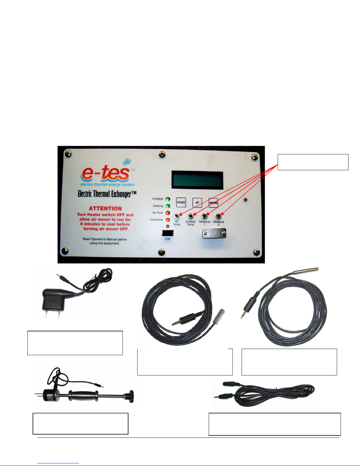
Remote pr
obe jacks.
E-TES SD REMOTE SENSOR - PROBE CONNECTION:
E-TES SD can be operated without using the optional remote sensors.
Overheating the structure may cause damage to structure or contents. Controlling the temperature is
important to prevent damage. If the external probes and remote exhaust controller are not used,
some other type of temperature control must be used to keep room temperature below 105ºF to
prevent overheating of the structure.
• Air Temperature Probe Default Setting: 00F
• Surface Temperature Probe Default Setting: 00F
• Moisture 1 Value Default Setting: 00%
• Moisture 2 Value Default Setting: 00%
To use the remote temperature or moisture probes to control the E-TES SD, simply plug the desired remote
sensor in the corresponding port on the front panel of the E-TES SD. Return to the MENU NAVIGATION
section to set the shutdown points for each probe.
Moisture Probe with 4’ cord
PGE5060
Surface Temperature Probe
with 10’ cord – AT200
Air Temperature Probe with
10’ cord – AT202
Moisture Hammer Probe with
4’ cord – AC102
Copyright Tes Drying Systems, 2014
10’ extension cord – AT204
Can be used with any of the E-TES probes
14
Page 15
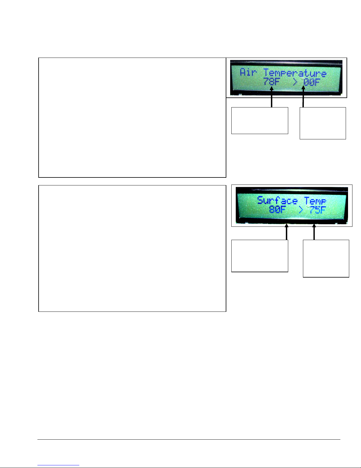
REMOTE PROBE SHUTDOWN:
If the measured readings of any of the remote probes exceed the set points, the green HEATING
light will turn off, indicating the unit is no longer heating.
AIR TEMPERATURE SHUTOFF
When the AIR TEMPERATURE measured by the probe
exceeds the set point the green HEATING light will turn off
indicating unit has shutoff the power to the heating elements.
The AIR TEMPERATURE screen will be displayed, flashing the
current temperature and the shutoff temperature set point.
When the temperature cools sufficiently the green HEATING
light will turn back on and the unit will again heat up.
The AIR TEMPERATURE SHUTOFF will not shutoff the
power to the heating elements if the AIR TEMPERATURE
probe is not connected.
SURFACE TEMPERATURE SHUTOFF
When the SURFACE TEMPERATURE measured by the probe
exceeds the set point the green HEATING light will turn off
indicating unit has shutoff the power to the heating elements.
The SURFACE TEMPERATURE screen will be displayed,
flashing the current temperature and the shutoff temperature set
point.
When the temperature cools sufficiently the green HEATING
light will turn back on and the unit will again heat up.
The SURFACE TEMPERATURE SHUTOFF will not shutoff
the power to the heating elements if the SURFACE
TEMPERATURE probe is not connected.
Current Air
Temperature
Current Surface
Temperature
Air
Temperature
Set Point
Surface
Temperature
Set Point
Copyright Tes Drying Systems, 2014
15
Page 16

Moisture Probes, then turn unit back ON.
MOISTURE 1 VALUE SHUTOFF
When the MOISTURE 1 VALUE measured by the probe drops
below the set point the green HEATING light will turn off
indicating unit has shutoff the power to the heating elements.
The MOISTURE 1 VALUE screen will be displayed, flashing the
current moisture percentage and the shutoff moisture value
percentage set point.
If the moisture level rises sufficiently the green HEATING light will
turn back on and the unit will again heat up.
The MOISTURE 1 VALUE SHUTOFF will not shutoff the power
to the heating elements if the MOISTURE 1 probe is not connected.
If the E-TES SD is ON when the Moisture 1 Probe is connected,
the MOISTURE 1 VALUE SHUTOFF will shutoff the power to
the heating elements even if the MOISTURE 1 VALUE is above the
set point. The power switch must be turned OFF & back ON to
reset E-TES to read the correct the moisture value and allow power
to the heating elements.
Do not plug-in or unplug the Moisture Probes while the E-TES SD
is ON. Turn E-TES OFF before plugging in or un-plugging
MOISTURE 2 VALUE SHUTOFF
When the MOISTURE 2 VALUE measured by the probe drops
below the set point the green HEATING light will turn off
indicating unit has shutoff the power to the heating elements.
The MOISTURE 2 VALUE screen will be displayed, flashing the
current moisture percentage and the shutoff moisture value
percentage set point.
If the moisture level rises sufficiently the green HEATING light will
turn back on and the unit will again heat up.
The MOISTURE 2 VALUE SHUTOFF will not shutoff the power
to the heating elements if the MOISTURE 2 probe is not connected.
If the E-TES SD is ON when the Moisture 2 Probe is connected,
the MOISTURE 2 VALUE SHUTOFF will shutoff the power to
the heating elements even if the MOISTURE 2 VALUE is above the
set point. The power switch must be turned OFF & back ON to
reset E-TES SD to read the correct the moisture value and allow
power to the heating elements.
Do not plug-in or unplug the Moisture Probes while the E-TES SD
is ON. Turn E-TES OFF before plugging in or un-plugging
Moisture Probes, then turn unit back ON.
Current Moisture
Level
Moisture Value
Set Point
To assure that the E-TES SD will
shut off & stay off when the
Moisture 1 Value drops below the
shutoff value, the Moisture Value 1
Shutoff MUST NOT be set below
10%.
To chart the Moisture 1 Value
without controlling the E-TES SD
set the Moisture Value 1 Shutoff to
0%.
Current Moisture
Level
Moisture Value
Set Point
To assure that the E-TES SD will
shut off & stay off when the
Moisture 2 Value drops below the
shutoff value, the Moisture Value 2
Shutoff MUST NOT be set below
10%.
To chart the Moisture 2 Value
without controlling the E-TES SD
set the Moisture Value 2 Shutoff to
0%.
Copyright Tes Drying Systems, 2014
16
Page 17
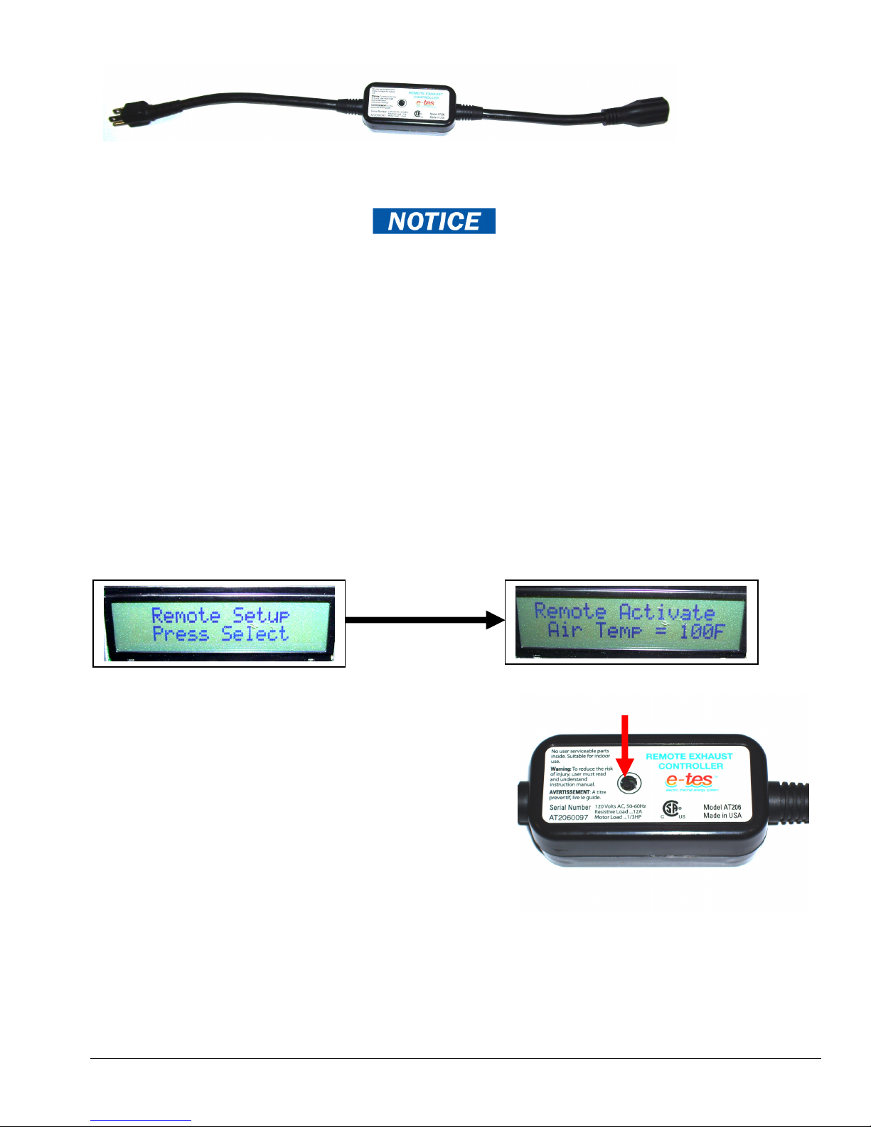
REMOTE EXHAUST CONTROLLER:
This allows you to set the temperature at which the E-TES SD will send a signal to turn on a
remote exhaust fan. The Remote Exhaust Controller can be located up to 100 yards away
from the E-TES SD unit and control electrical devices with a total amp load up to 15amps.
The Remote Air Temperature Sensor must be connected to the E-TES SD
to operate the Remote Exhaust Controller.
Overheating the structure may cause damage to structure or contents. Ambient room temperature
should be maintained below 105ºF during the drying process. Controlling the temperature is
important to prevent damage. If the external probes and Remote Exhaust Controller are not used,
some other type of temperature control must be used to prevent overheating the structure.
Plug the Remote Exhaust Controller into a 120VAC wall outlet and then plug your exhaust
fan into the Remote Exhaust Fan Control. Turn the exhaust fan switch to the ON position.
When the air temperature reaches the set point the E-TES SD will activate the Remote
Exhaust Fan Control to send power to the exhaust fan to turn it on.
To adjust the set point use the UP & DOWN arrow keys to move to the REMOTE SETUP
screen. Press - SELECT to enter the temperature setup screen and use the UP & DOWN
arrows to set the Remote Exhaust Controller turn on temperature.
The Remote Exhaust Controller must be calibrated
to work with the signal from a specific E-TES SD.
To calibrate the Remote Exhaust Controller:
1. Push the reset button on the Controller as you
plug the Controller into the wall outlet. This will
clear the memory of the control.
2. Turn the E-TES SD unit on and scroll to the
REMOTE SETUP screen then press select.
3. Use the UP & DOWN arrows to set the Remote
Exhaust Controller turn on temperature. This
will send a signal to calibrate the Remote Exhaust Controller.
If you are using multiple E-TES SD units with multiple remotes, turn the other E-TES SD
units OFF as you calibrate each remote to a specific E-TES SD to prevent signals from the
other units from interrupting your calibration.
SELECT
RESET BUTTON
Copyright Tes Drying Systems, 2014
17
Page 18

DUAL CIRCUIT INDICATOR:
The amp draw of the two circuits of the E-TES SD 120 Volt unit requires that the two power cords be plugged into
separate outlets. To assist you in determining if the cords are plugged into separate circuits, The E-TES SD 120
Volt unit is now equipped with a dual circuit indicator.
With both power cords plugged into outlets, connected to the E-TES SD 120 Volt unit and the GFCI’s reset, turn
E-TES SD unit power switch to the ON position. Observe Dual Circuit indicator light next to rocker switch. If
green light is ON, cords are on separate circuits and you can proceed with set-up. If light is OFF both cords are on
the same circuit and one cord must be moved, one cord is not supplying power. Display will light, Power & Heating
lights may turn ON if Cord #1 has power even if Cord #2 is disconnected. Both cords must be connected and
Dual circuit indicator light must be ON for proper heater operation.
When cords are on separate circuits and green Dual Circuit indicator light is on proceed with set-up.
Improper wiring of electrical outlets can prevent the indicator light from turning on. Using an overloaded circuit
may cause the circuit breaker to blow even if both cords are on separate circuits.
An AC128 SureTest Circuit Analyzer can be used to test the outlet wiring and existing load to reduce the chances of
the circuit breakers tripping during E-TES SD operation.
CORD #1 CONNECTOR CORD #2 CONNECTOR
DUAL CIRCUIT INDICATOR LIGHT
With Cord #2 disconnected or connected to a dead outlet, as
long as there is power to Cord #1 and Cord #1 is connected to
AC128
SURETEST CIRCUIT ANALYZER
the E-TES SD 120 Volt unit, the LED display and the POWER
& HEATING indicator lights will still function, but the heater
will only operate at one half of its rated heating capacity.
Copyright Tes Drying Systems, 2014
18
Page 19
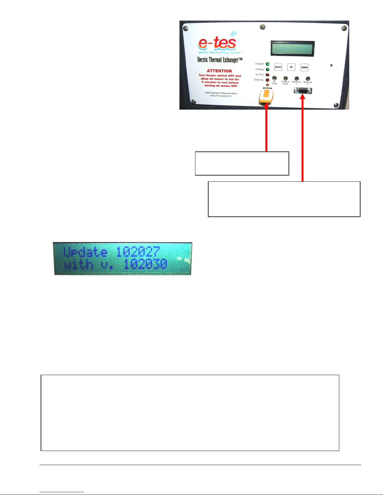
SOFTWARE UPDATES:
Computer Serial Port for E
-
TES SD
The E-TES SD software can be
reprogrammed or updated using a removable
data storage device such as an USB Flash
Drive or Memory Stick. When software
updates are available you will be contacted by
your distributor. You will receive a Flash
Drive preloaded with the new software or the
software can be e-mailed to you to be
downloaded onto your own Flash Drive or
Memory Stick.
To update the E-TES SD software, with the
E-TES SD OFF, simply plug the memory
devise, with the E-TES SD software file, into
USB port on front panel. Push and hold both
the UP & DOWN buttons as you turn the ETES SD Power switch ON. The software will
automatically be updated. The display will read
UPDATE along with the old version and new
version numbers. The screen will not change
until the update is complete.
Then remove the memory device and turn the
switch off.
REMOVABLE USB
MEMORY DEVICE
manufacturer use only, used for testing
and formatting of microprocessor
If your USB Flash Drive is protected by a password, you will need to
temporarily disable the password to connect it to the E-TES SD. This goes
for installing the activation key, installing updates, and downloading the job
data.
SOFTWARE UPDATE SCREEN
Shows the old software version number and the
version number of the new software which is
replacing the old version
From our tests it was not necessary to disable the Flash Drive’s auto-run
programs, such as the SanDisk U3 Launchpad to work with the E-TES SD.
Copyright Tes Drying Systems, 2014
19
Page 20
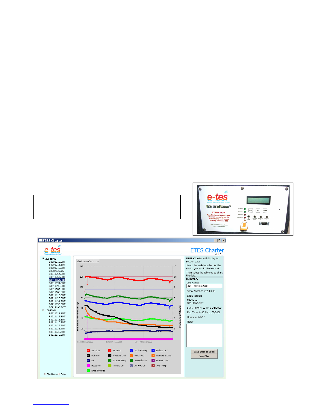
DATA CHARTING:
E-TES Charter Preview Screen
The E-TES SD now has the ability to measure and store data regarding the operating status of the unit and the
environmental conditions during the drying process. The E-TES SD will hold up to one month of continuous
operational data. The Charter data is sorted by the serial number of each unit and each job is given a file number so
one USB Flash Drive can be used for multiple E-TES SD units.
Always check & set the date & time on the E-TES SD display before each job. (See Page 13)
Starting a job with an incorrect date or time setting may create a corrupt job file and prevent the data from
being downloaded or accessed.
Optional E-TES SD Charter Software is required to download, read and graph the data log information.
The Charter software is available to download free online at tesdryingsystem.com.
The E-TES SD job data can be retrieved by inserting a removable data storage device such as a Flash Drive or
Memory Stick into the USB port on front panel. After inserting the flash drive into the USB port, turn the power
switch ON to log data from the E-TES SD unit. When Flash Drive stops flashing, and the Updating USB - Do
Not Remove screen is no longer showing, turn the switch off and remove the Flash Drive. Flash Drive can then
be connected to the USB port on your computer to download the data.
The E-TES SD Charter software will allow you to compile reports for insurance adjusters or homeowners to
support your drying procedures and billing. On the E-TES Charter preview screen you can modify the graph by
clicking on the keys at the bottom of the screen to add or delete different data you want displayed on your graph.
The job can be named and data is exported to Excel to create job files, graphs and reports. Multiple job files can be
joined to create a new single job file for reports.
DATA RETREIVED USING A REMOVABLE USB
MEMORY DEVICE
Copyright Tes Drying Systems, 2014
20
Page 21
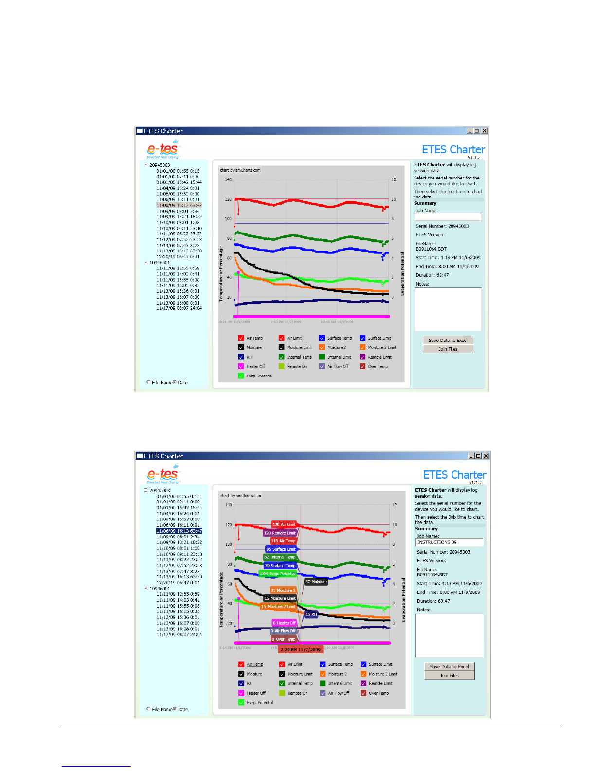
The jobs files are sorted by the serial number of the E-TES SD unit from which the data was retrieved. Serial
numbers starting with “2” are 240 volt units and serial numbers starting with “1” are 120 volt units. The jobs are
listed by either file name or date. Select File Name or Date at the bottom of the page to determine how the jobs will
be displayed. When changing from File Name or Date an error message may be displayed on your computer. Just
click continue and the Charter will re-open and display as you selected. In the example on the previous page the job
file names are listed. The file names such as B0911064 consist of the year, month and day the job was started and a
number to differentiate various jobs started on the same day. The example below shows the job files displayed by
date.
By moving your cursor over the graph it will display flags with the readings for individual points on the graph lines,
as shown in the example below.
Copyright Tes Drying Systems, 2014
21
Page 22
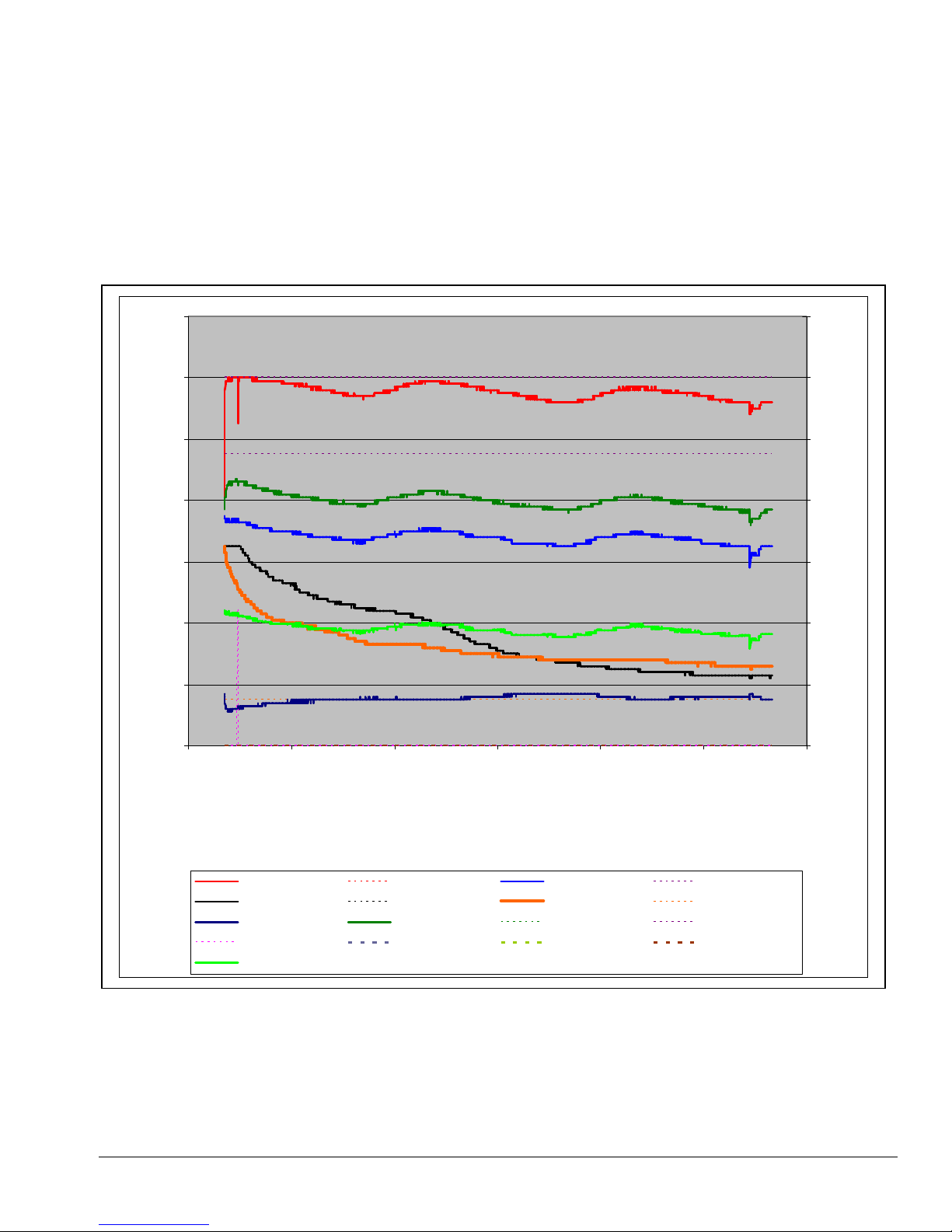
In this example of an Excel graph, you can see that the AIR TEMPERATURE LIMIT and REMOTE LIMIT
were set at 120°F, the SURFACE TEMPERATURE LIMIT was set at 95°F, and the MOISTURE 1 LIMIT and
MOISTURE 2 LIMIT were set at 15%. The RH or Relative humidity stayed around 15 to 20%. The INTERNAL
TEMPERATURE stayed around 80-90°F. The E-TES unit never had the AIR FLOW turn off or an
OVERTEMP condition.
The AIR TEMPERATURE PROBE reading exceeded the limit twice and turned the heater off for two short
periods. When the air temperature cooled the heater turned back on both times.
The moisture content of the wood started over 60%. The MOISTURE 1 VALUE and MOISTURE 2 VALUE
both dropped but stayed above the 15% limit and did not shut the heater off.
140
12
120
10
100
8
80
6
60
Degree or Percent
40
4
Evaporation Potential
2
20
0
0
-2
11/6/09 12:00 PM
Air Temp Air Limit Surface Temp Surface Limit
Moisture Moisture Limit Moisture 2 Moisture 2 Limit
RH Internal Temp x-Internal Limit Remote Limit
Heater Off Air Flow Off x-Remote On Over Temp
Evap Potential
11/7/09 12:00 AM
You can modify the graph to chart the readings which you decide are the most relevant to each job. For this chart:
the following changes were made in the graph:
• The REMOTE ON was not charted.
• The INTERNAL LIMIT was not charted.
Copyright Tes Drying Systems, 2014
11/7/09 12:00 PM
22
11/8/09 12:00 AM
11/8/09 12:00 PM
11/9/09 12:00 AM
11/9/09 12:00 PM
Page 23
Heater Operation Procedure
Section
3
C
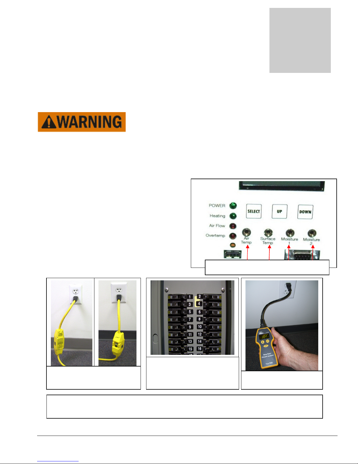
onnect Remote Sensors here
CHECK CIRCUIT BREAKERS
U
SE CIRCUIT ANALYZ
ER
PLUG CORDS INTO
TWO
CIRCUITS
Knowledge of the proper operation of the
heater and heat exchange system is required for safe operation and to
keep heater and components operating properly.
1) Read and understand the Remote Probe connection procedures and Menu Navigation in SECTION #2
before proceeding with set-up and operation.
2) Place the E-TES SD unit as required for your drying situation. (SEE SET-UP SECTION #2)
3) Connect Remote Sensors as needed, place Remote
Sensors in desired locations.
4) Connect the two GFCI E-TES power cords to two
different 120volt outlets. If you have a 20amp circuit
one air mover should be able to be plugged into the
same circuit as one GFCI E-TES SD power cord.
Check the circuit breakers and the amp draw of your
air mover to determine if the circuit can handle the
load. If you are unsure, plug the air movers into an
outlet on a third circuit.
OUTLETS ON TWO SEPARATE
For more information on the capabilities and use of the AC128 Circuit Analyzer, see the Circuit
Copyright Tes Drying Systems, 2014
TO DETERMINE THE
AMPERAGE CAPACITY FOR
EACH CIRCUIT
Analyzer operator’s manual
23
TO CHECK CIRCUIT LOAD
Page 24
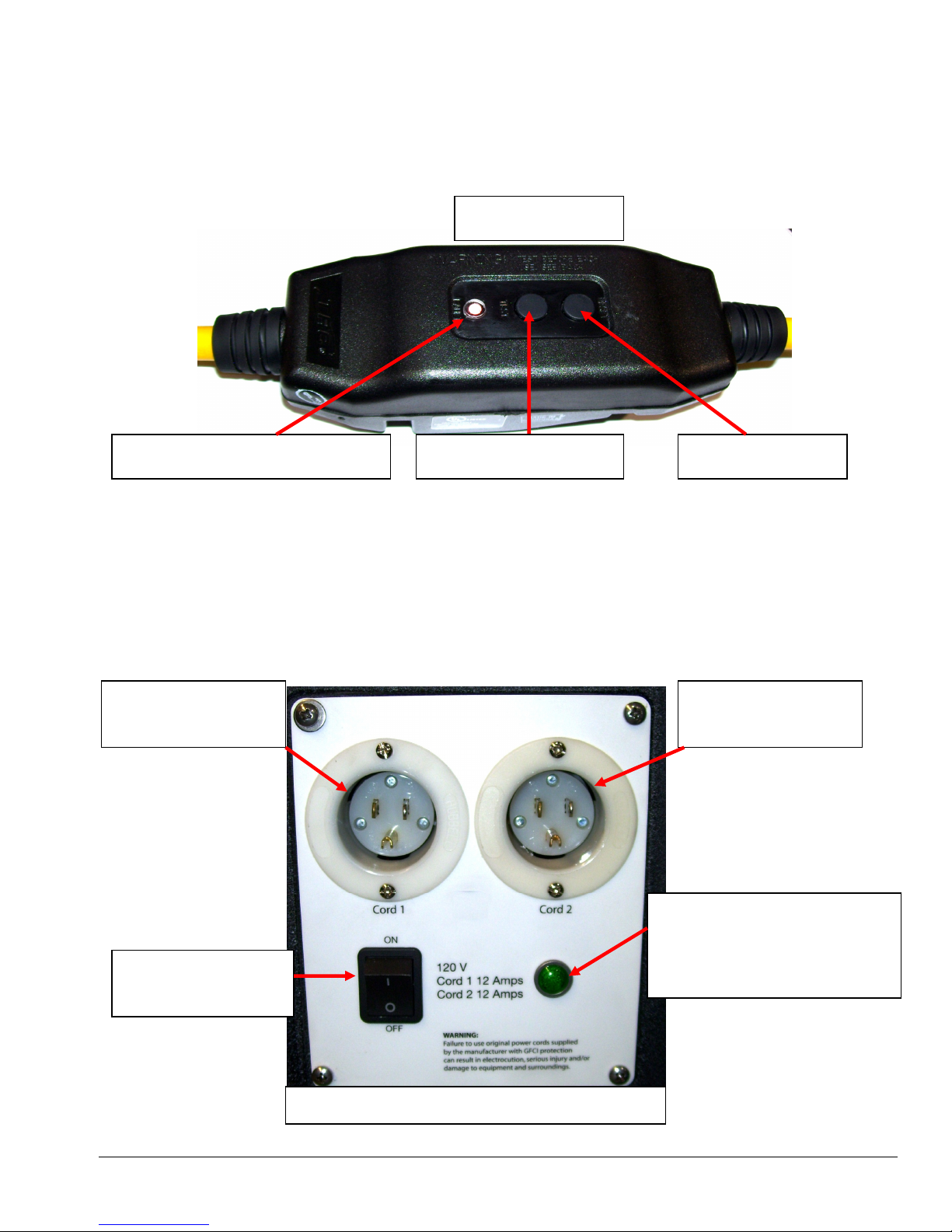
5) Make sure E-TES SD unit power switch is in the OFF position, and then connect the receptacle end of the
E-TES SD 120VOLT LP SWITCH PLATE
RESET BUTTON
FAULT INDICATOR LIGHT
GFCI TEST
BUTTON
GFCI MODULE
GFCI cords to E-TES SD unit. Reset GFCI on both power cords. Push TEST button to test GFCI and if
RESET button pops out and the red FAULT Indicator light turns on, push RESET button back in and
proceed with set-up. If RESET button does not pop out when TEST button is pushed, replace cord or contact
your nearest service center for advice or assistance. When operating properly the red FAULT light on the GFCI
unit will be OFF. Once the unit is plugged in and reset, if there is a power outage the GFCI will reset
automatically. If tripped by a ground fault incident, the GFCI must be manually reset
6) Turn E-TES SD unit power switch to the ON position. Observe Dual Circuit indicator light next to rocker
switch. If green light is ON, cords are on separate circuits and you can proceed with set-up. If light is OFF both
cords are on the same circuit and one cord must be moved. When cords are on separate circuits and green Dual
Circuit indicator light is on proceed with set-up.
If Cord #1 is connected properly and supplying power to the Cord #1 connector, the LED display,
POWER light and HEATING light will operate normally even if Cord #2 is disconnected or
connected to a dead outlet. The unit will still operate, but at only one half of its rated heat output.
CONNECT CORD
#1 HERE
CONNECT CORD
#2 HERE
DUAL CIRCUIT
INDICATOR LIGHT
E-TES SD POWER
SWITCH
Must be ON for proper
operation
Copyright Tes Drying Systems, 2014
24
Page 25
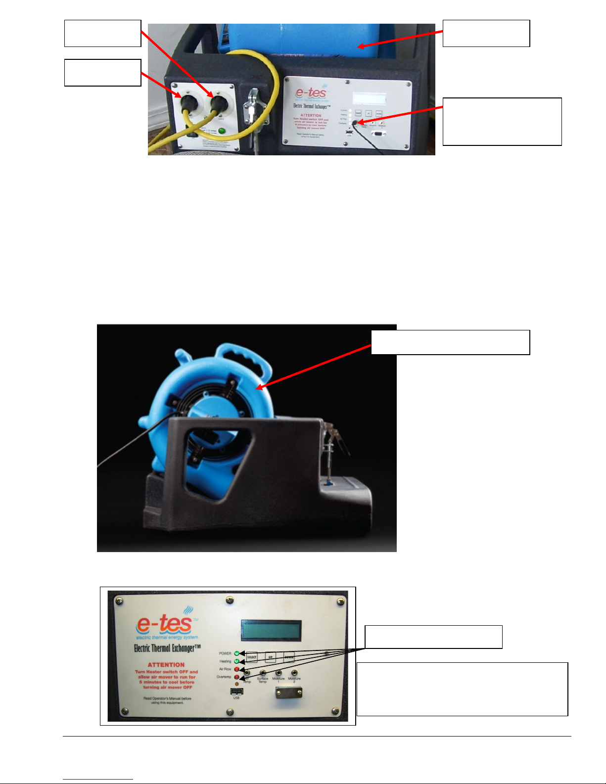
CORD #2
CORD #1
PROBE
AIR MOVER
REMOTE AIR
TEMPERATURE
7) Set the Remote Sensor activation points at the temperature or moisture level required for your application.
(See SECTION 2 for Instruction on how to set activation points.)
8) If you are planning using the data files which the E-TES SD will log during this job, check the current date &
time on the E-TES SD display. Set time & date to correct settings.
(See SECTION 2 – Page 13 for Instruction on how to set the date & time.)
Once set to the correct date & time, turn the E-TES SD OFF & then back ON to start new job file with
correct start time & date.
9) Place an air mover into the E-TES SD unit. Plug in the air mover and turn the air mover switch ON.
OMNIDRY 2.9 AIR MOVER
10) Observe indicator lights. When both green lights are illuminated system is operating properly and the heating
elements are getting power. If the green HEATING light is off, the unit is not heating properly.
INDICATOR LIGHTS
For the E-TES SD unit to heat up, both
the POWER light and HEATING light
must be on.
Copyright Tes Drying Systems, 2014
25
Page 26
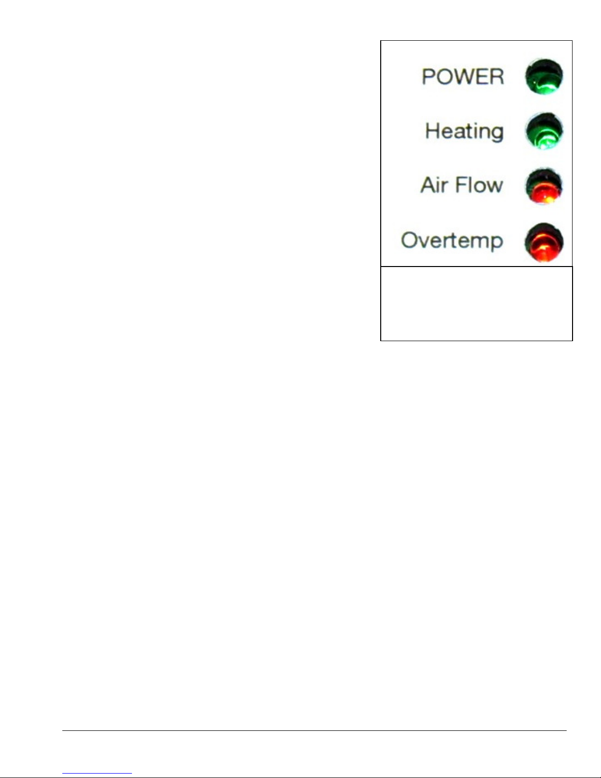
• POWER – When the green POWER light is lighted it
indicates that the heater switch is in the ON position and
the power has been supplied to the heater. (If the green
POWER light is OFF the other lights will not light.)
• HEATING – When the second green light, the
HEATING light, is lighted it indicates that power is being
supplied to the heating elements and the unit should be
heating. If cord #2 is unplugged the heating light can still
turn ON. To assure proper heating, make sure the Dual
Circuit indicator light is ON.
• AIR FLOW – When the first red light, the AIR FLOW
light, is lighted it indicates that there is not sufficient air
flow for the heater to operate or the airflow switch is
malfunctioning and power is being shutoff to the heating
elements. When the AIR FLOW light is ON, the
HEATING light should be OFF.
During normal heater operation, only
the POWER light and HEATING
light will be on.
• OVERTEMP – When the second red light, the
OVERTEMP light, is lighted it indicates that the either
If either red light turns ON, the green
HEATING light will turn OFF.
heating element temperature, internal temperature or the
snout temperature is above the safe operating range and power being shutoff to the heating elements.
When the OVERTEMP light is ON, the HEATING light should be OFF.
If the green HEATING light is not lighted look for the following:
o If the two red lights are OFF, but the HEATING light does not come on, make sure you have power
to E-TES SD and the green POWER light is ON. Check your set points on your remote sensors. One
or more of them may be reading beyond their set point and have shut off the power to the heating
elements. Usually when this happens the display screen will flash indicating the sensor which has signaled
the unit to shutdown. Reset your activation points, disconnect or replace the sensors as needed.
o If the green HEATING light is OFF and the red AIR FLOW light is ON, the air flow through the E-
TES SD unit is not enough to allow the Air Pressure sensor to be engaged. Check the air mover
operation and check the circuit providing power to the air mover to assure proper air flow. The Air
Pressure Sensor readings can be checked or recalibrated as needed. See the Air Flow Set-up
instructions on page 13. If the AIR FLOW light does not turn off, there could be If the air mover is
operating properly, the tubing to one of the pressure ports may be restricted or disconnected. If the
tubing & barbs are clear and the tubing is in good condition, the air pressure sensor may be defective.
Contact your nearest service center for advice or assistance.
o If the green HEATING light is OFF and last red light, the OVERTEMP light is ON the heating
elements, snout temperature or internal temperature may have reached the maximum temperature and
the power to the heating elements has been cut-off to allow the unit to cool. Turn the heater switch
OFF. Make sure the air mover is ON and remove any restriction to allow more air flow to cool the ETES SD. When cool turn the heater switch back ON. If the unit has cooled and the OVERTEMP light
stays on, there could be a loose wire or one of the temperature sensors could be defective. Contact your
nearest service center for advice or assistance.
Copyright Tes Drying Systems, 2014
26
Page 27
11) Observe unit operation to be sure that air flow is kept at a high enough flow rate to prevent the heater from
turning ON and OFF. Remove restrictions to increase air flow as needed to maintain proper air flow rate.
12) Make sure circuit breakers are not tripping and the power supply to the air mover and E-TES SD unit will not
be interrupted.
13) When the E-TES SD unit is adjusted properly and operating normally, the unit can be left alone during
operation.
HEATER SHUTDOWN PROCEDURE
1) Turn the heater switch to the OFF position.
2) Keep the air mover running for 5 minutes to cool the heating elements.
3) When the unit has cooled turn the air mover OFF.
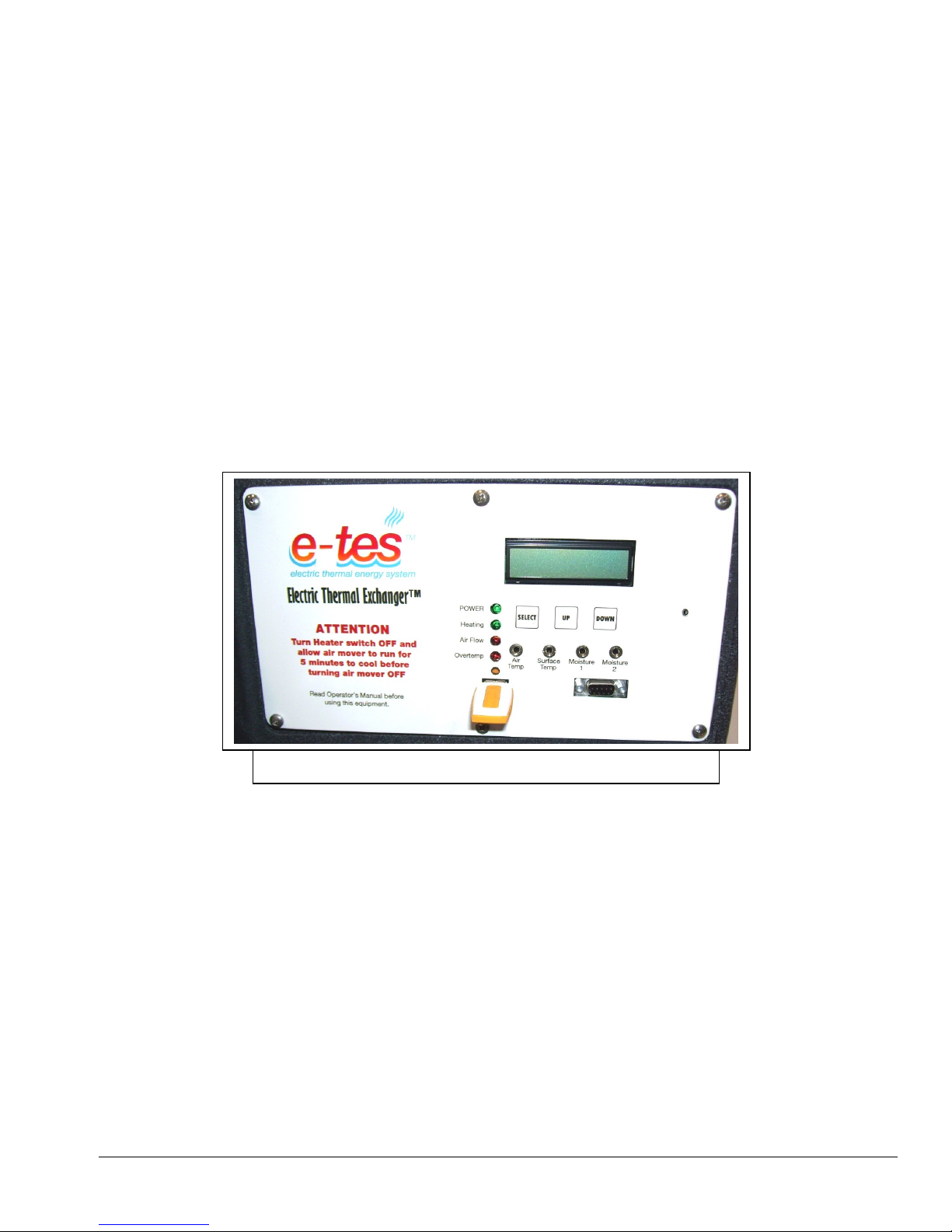
4) If required, insert USB Flash Drive into the USB port on the E-TES SD front panel, turn switch ON to log
data from job. When Flash Drive stops flashing, turn switch off, remove the Flash Drive and proceed with
shutdown. (Display will freeze on Updating USB - Do Not Remove screen while data is downloading.)
Flash Drive inserted into USB port to download job data.
E-TES SD Charter software is required to view and chart job data log
information downloaded from the E-TES SD.
(See instructions on page 20)
5) Disconnect the power cords from the power outlets and heater connections. Roll up and store cords.
6) Remove and store air movers and E-TES SD Electric Thermal Exchanger.
Copyright Tes Drying Systems, 2014
27
Page 28
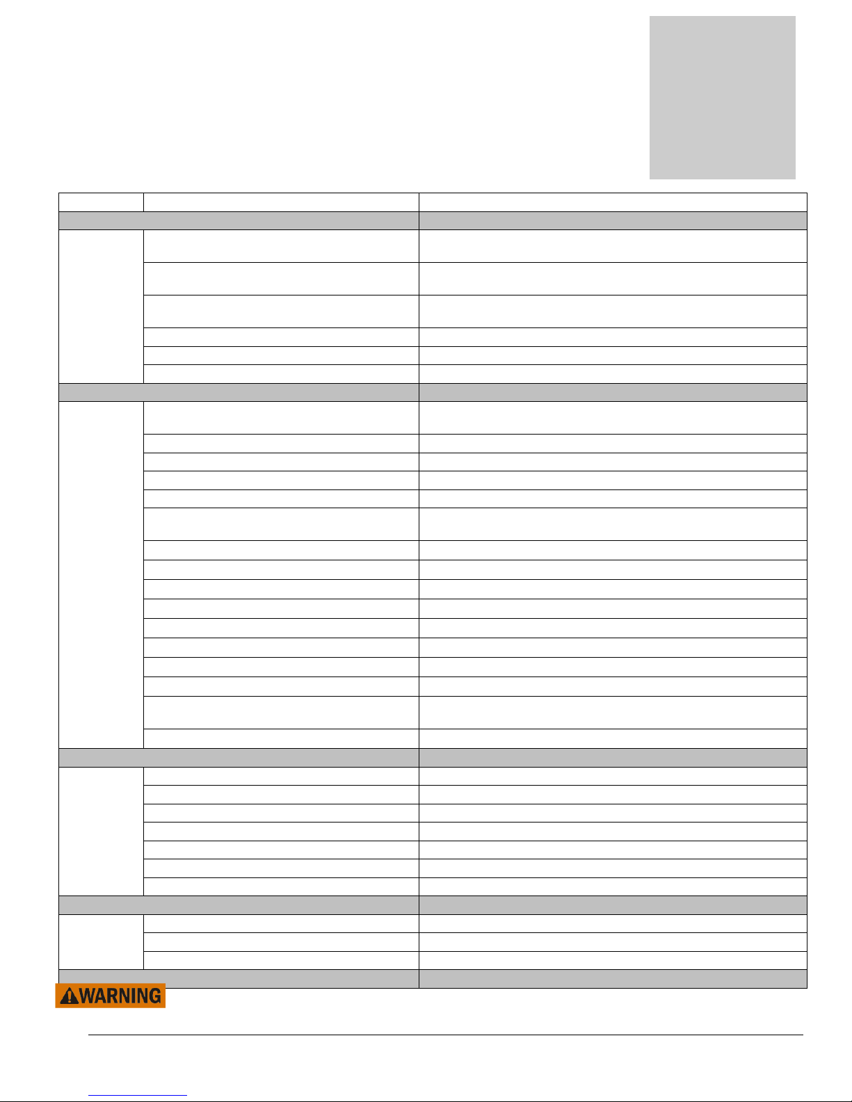
Problem
Section
3
E-TES SD Troubleshooting
Cause Solution
Circuit
Breaker Both cords on one circuit Move one cord to a separate circuit
Move plug to another outlet & circuit or disconnect other
Blowing Too much current demand on circuit
Circuit breaker faulty
Heating Element faulty Replace Heating Element
Faulty power cord Replace cord NM4407
Faulty switches or internal wiring Check wiring & test switches - Repair as needed *
Unit Not
Heating Heater Switch in OFF position Turn switch to ON position
Building circuit breaker tripped. Reset breakers or move cords to other outlets
HEATING GFCI tripped Reset GFCI
Light OFF Faulty power cord Replace cord
(GREEN) Faulty GFCI Replace cord (NM4407A) or replace GFCI
Air Mover not running
Low Air Flow Remove restrictions to maintain adequate air flow
Probe Temperature set too low Reset Air Temp & Surface Temp set points
Moisture 1 or 2 set point too low Reset Moisture Value set points
Moisture 1 or 2 Value stuck at zero With probe connected, turn Power switch OFF then ON
Faulty Remote probes Check probe readings – Replace probes as needed
Internal Temperature sensor faulty Replace circuit board
Faulty Snout Temperature Sensor Replace Snout Temperature Sensor
Faulty switches or internal wiring Check wiring & test switches - Repair as needed *
Faulty Safety Temperature Switch
Faulty indicator light Replace light
POWER Heater Switch in OFF position Turn switch to ON position
Light OFF Building circuit breaker tripped. Reset breakers or move cords to other outlets
(GREEN) GFCI tripped Reset GFCI
Faulty power cord Replace cord
Faulty GFCI Replace cord (NM4407) or GFCI
Faulty switches or internal wiring Check wiring & test switches - Repair as needed *
Faulty indicator light Replace light
Start-Up Memory Locked Up Re-initialize Memory (See page 33)
Error Software Corrupted Reprogram processor (See page 19)
Display Circuit Board Faulty Replace circuit board
* To reduce the risk of injury, repairs to electrical systems should only be performed by experienced
technicians. Contact your nearest service center for assistance.
Copyright Tes Drying Systems, 2014
devices from this circuit.
Move plug to another outlet & circuit or have electrician
replace circuit breaker
Turn on air mover or check power to air mover.
Repair or replace air mover as needed
Observe Lights to determine function
Correct condition or Repair as needed *
28
Page 29
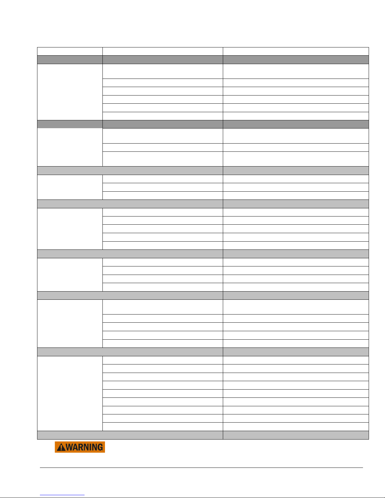
E-TES SD Troubleshooting Continued
Problem Cause Solution
Turn on air mover or check power to air mover.
Air Flow Air Mover not running
Repair or replace air mover as needed
Light ON Low Air Flow Remove restrictions to maintain adequate air flow
(RED) Air Pressure Tubing Damaged Replace Tubing
Air Pressure Barbs plugged Clean out or replace barbs
Air Pressure Sensor not calibrated Recalibrate Air Flow Switch (See page 13)
Faulty Circuit Board Sensor Replace Circuit Board
OVERTEMP
Light ON Unit Overheated
Let unit cool. Allow temperature Switch to cool off
and reset.
(RED) Faulty switches or internal wiring Check wiring & test switches - Repair as needed *
Observe Lights to determine function
Faulty Temperature Switch
Correct condition or Repair as needed *
Remote Sensors Faulty sensor Replace sensor
Not reading Circuit board faulty Replace circuit board
Software Corrupted Reprogram processor (See page 19)
Display Blank No Power Check green power light – See green light section
Faulty switches or internal wiring Check wiring & test switches - Repair as needed *
Faulty indicator Display Replace Circuit Board
Processor Locked Up Reset Processor (See page 35)
Software Corrupted Reprogram processor (See page 19)
Clock, Date or Temporary Glitch Reset Date & Time (See page 13)
Time Wrong Software Corrupted Reprogram processor
Battery Dead
Replace Battery – Use Panasonic BR-2/3A only
Circuit Board Faulty Replace Circuit Board
Check instructions for available key options for
Cannot move Wrong key being pushed
each screen
through menu Process locked up Turn power switch OFF and back ON to reset
Faulty push buttons Replace circuit board
Faulty circuit board Replace circuit board
Software corrupted Reprogram processor (See page 19)
System Overheating Snout Air Flow is restricted Remove air flow restriction
Air Flow Too Low Turn Air Mover to higher speed
Faulty switches or internal wiring Check wiring & test switches - Repair as needed *
Faulty Safety Temperature Switch Replace one or both temperature switch
Faulty Snout Temperature Sensor Replace Snout Temperature Sensor
Room Temperature too high Use Exhaust Controllers to cool room
Internal Temperature sensor faulty Replace circuit board
Remote temp sensor set point too high Reset air & surface temperature set points
Defective remote sensors Replace air or surface temperature sensors
* To reduce the risk of injury, repairs to electrical systems should only be performed by
experienced technicians. Contact your nearest service center for assistance.
Copyright Tes Drying Systems, 2014
29
Page 30
Ind
icates Light is ON
HEATING
AIR FLOW
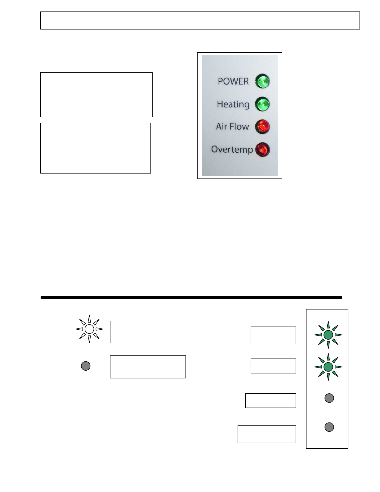
E-TES SD 120 VOLT INDICATOR LIGHT PANEL CONFIGURATIONS
E-TES SD INDICATOR LIGHTS:
During normal operation both Green lights
will be ON when the unit is heating.
POWER LIGHT
When the green POWER light is
ON, the switch is on and power is
being supplied to the unit.
HEATING LIGHT
When the green HEATING light
is ON, the controls are all within
limits and power is being supplied
to the heating elements
AIR FLOW LIGHT & OVERTEMP LIGHT
If either red light is ON, the green HEATING light will turn off, indicating that the
unit is no longer heating.
If Cord #1 has power the POWER light and the green HEATING light can still turn
ON, even if Cord #2 is disconnected. Make sure both cords are connected and DUAL
CIRCUIT INDICATOR light is ON for proper heater operation.
Indicates Light is OFF
When both of the green lights are ON and
both red lights are OFF, as shown here, the
heater is operating normally and the
heating elements are receiving power.
Dual Circuit Indicator light must also be
ON for proper heater operation.
POWER
OVERTEMP
Copyright Tes Drying Systems, 2014
30
Page 31
HEATING
OVERTEMP
AIR FLOW
HEATING
AIR FLOW
HEATING
AIR FLOW
POWER
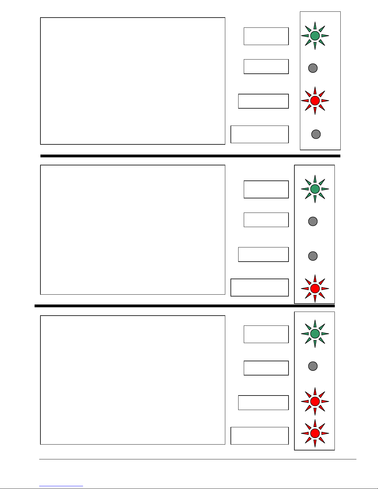
When the red AIR FLOW light is ON, the air flow is too
low for proper operation and the unit has shutoff the power
to the heating elements. This will cause the green
HEATING light to turn OFF.
If the air flow is restored, the red AIR FLOW light will turn
off, the green HEATING light will turn back on and the
unit will again heat up.
When the red OVERTEMP light is ON, one or more of
three over heating conditions has been reached. The internal
temperature measured at the circuit board has exceeded
140°F, the temperature of the Snout Temperature sensor has
reached 170ºF or the heating element box temperature has
exceeded 210°F. The red OVERTEMP light comes on when
the temperature measured by any one of these sensor
exceeds its set point the unit will shutoff the power to the
heating elements. This will also cause the green HEATING
light to turn OFF.
When the temperature cools sufficiently the red
OVERTEMP light will turn off, the green HEATING
light will turn back on and the unit will again heat up.
In some situations when the air flow is too low and the
AIRFLOW light comes ON, the E-TES will also over heat
and cause the OVERTEMP light to come ON too.
When the air flow is restored the red AIR FLOW light will
turn OFF and when the temperature cools sufficiently the
red OVERTEMP light will turn OFF, the green
HEATING light will turn back ON and the unit will again
heat up.
POWER
POWER
OVERTEMP
OVERTEMP
Copyright Tes Drying Systems, 2014
31
Page 32
HEATING
OVERTEMP
AIR FLOW
HEAT
ING
AIR FLOW
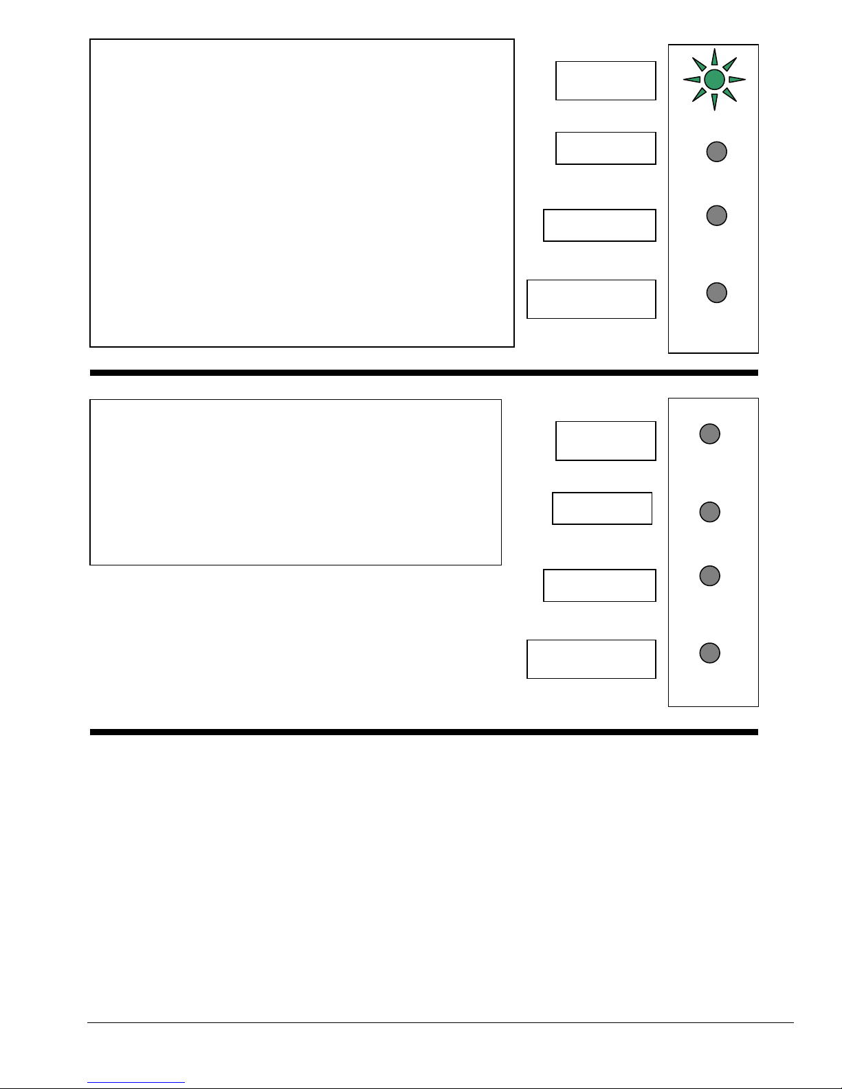
When the green HEATING light is OFF, but neither of the
red lights is ON, it usually means that one on the remote
sensors is getting a reading past its set point.
When the AIR TEMPERATURE, SURFACE
TEMPERATURE or MOISTURE VALUE measured by the
corresponding probe exceeds the set point the green
HEATING light will turn OFF indicating unit has shutoff the
power to the heating elements.
The screen for the sensor sending the shutdown reading will
be displayed, flashing the current reading and the shutoff set
point.
When the temperature cools sufficiently or the moisture level
rises the green HEATING light will turn back ON and the
unit will again heat up.
POWER
The power supply to the E-TES SD unit has been cut off.
Check the building circuit breakers and the GFCI cords
and reset as needed. There also could be a malfunction in
the heater switch or other internal wiring. Contact your
nearest service center for assistance.
POWER
OVERTEMP
ALL OTHER LIGHT COMBINATIONS WILL ONLY OCCUR WHEN THERE IS A
MALFUNCTION IN THE SYSTEM. IF YOU HAVE A LIGHT COMBINATION NOT SHOWN
AND DESCRIBED HERE, CONTACT YOUR NEAREST SERVICE CENTER FOR ADVICE OR
ASSISTANCE.
Copyright Tes Drying Systems, 2014
32
Page 33
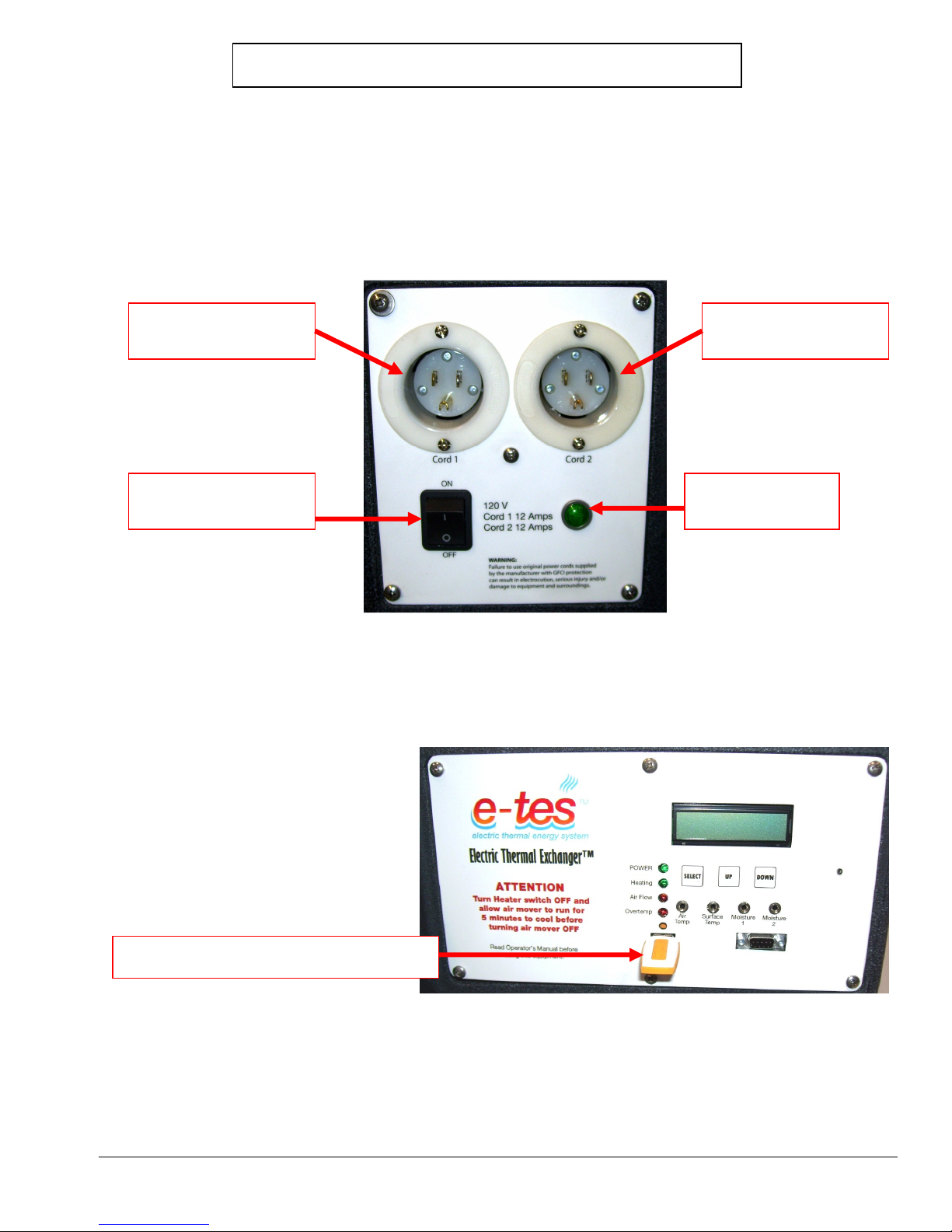
On occasion the memory on the E-TES SD units will need to be re-initialized. When this happens, the ETES SD will not function and the display will show the Start-up Error screen when the power switch is
turned on or will not accept new software updates. These problems can usually be corrected in the field by reinitializing the E-TES SD memory.
E-TES SD 120 Re-initializing the Memory
1. Connect the power cord to the power source and reset the GFCI.
2. Connect the power cord to the E-TES SD. For 120volt units only cord #1 will need
to be connected.
E-TES SD 120 Volt
CORD #1
E-TES SD 120 Volt
CORD #2
E-TES SD 120 Volt
POWER SWITCH
Dual Circuit
Indicator Light
3. If you are updating the software, insert the flash drive with the new software into
the USB port on the front panel of the E-TES SD.
Flash drive in E-TES SD USB Port
Copyright Tes Drying Systems, 2014
33
Page 34
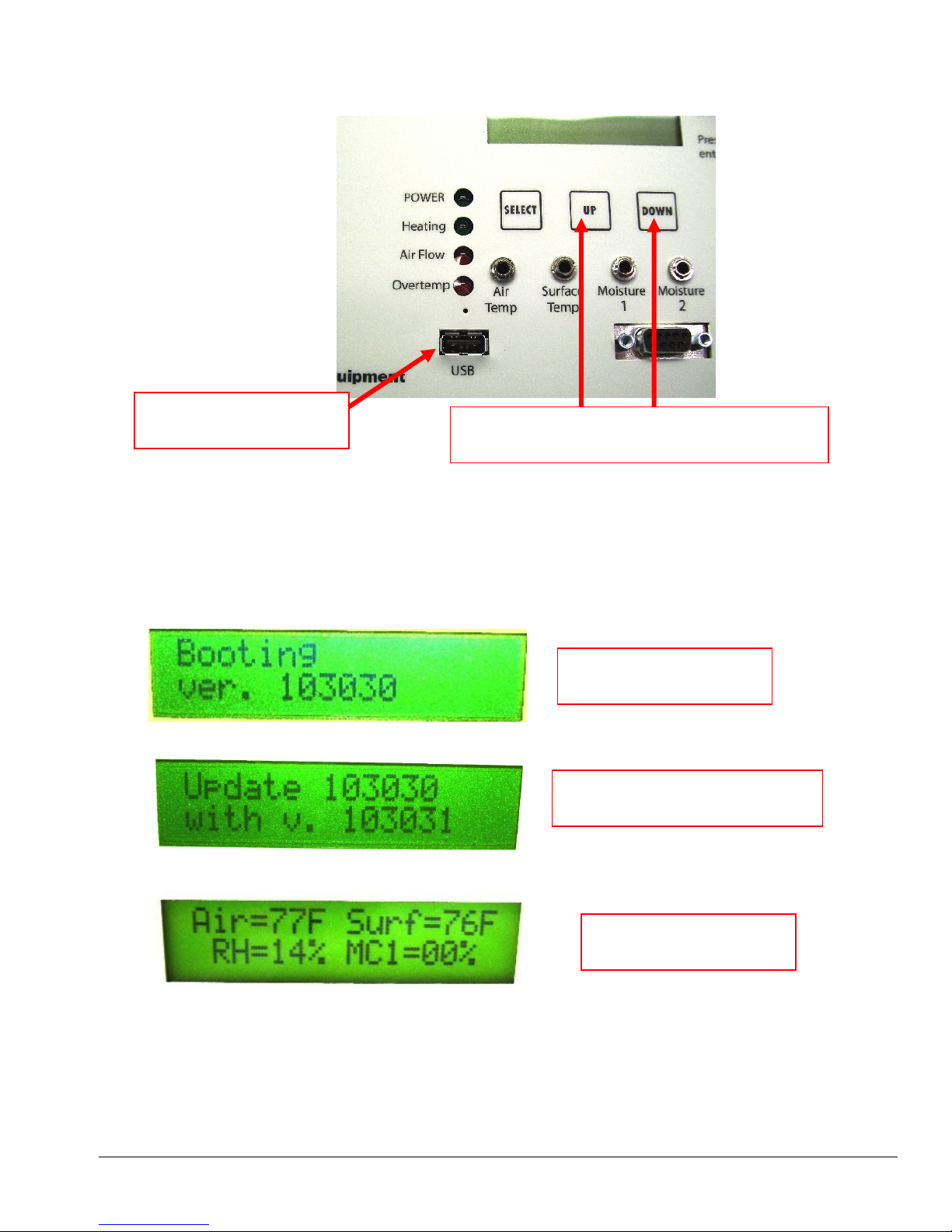
4. Press and hold both the UP button and DOWN button while your turn the power
switch ON.
E-TES SD USB PORT
Hold both the UP button and DOWN
button while you turn the power switch ON.
5. Continue to hold both the UP button and DOWN button until the advances past
the booting screen. If you are updating the software you can release the buttons as
soon as you see the Update Screen. Once the memory is re-initialized and the
software is updated the unit should advance to the main screen and operate
normally. If not, contact you E-TES SD distributor for advice or assistance.
Copyright Tes Drying Systems, 2014
34
E-TES SD
Booting Screen
E-TES SD
Software Update Screen
E-TES SD
Main Screen
Page 35
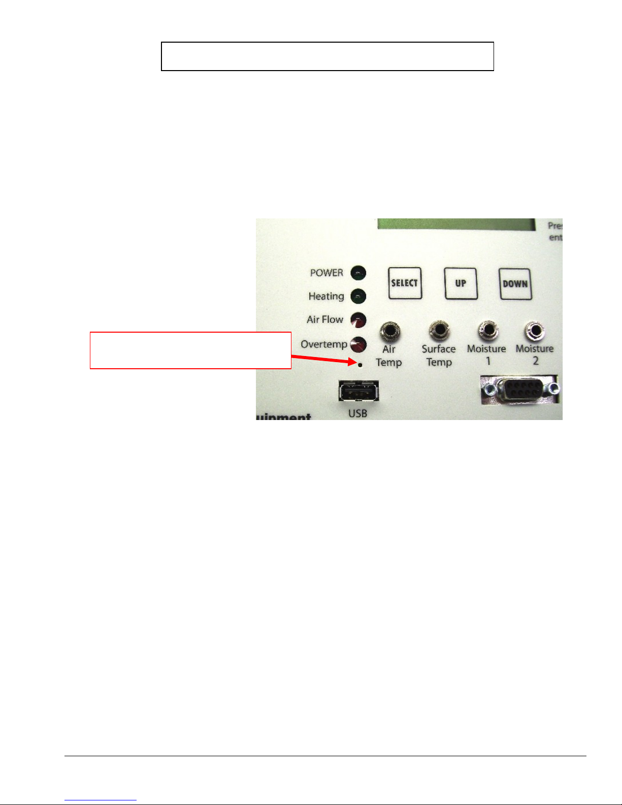
E-TES SD 120 Resetting the Processor
On occasion the processor on the E-TES SD units will lock up. When this happens, the E-TES SD will not
function and the display will show only a line of rectangles or will remain blank when the power switch is
turned on. This problem can easily be corrected in the field by resetting the processor. Sometimes simply
clicking the Power Switch OFF and back ON quickly will unlock and reset the processor. If not, follow these
instructions:
E-TES SD machines have a small hole in the front face plate just above the USB port and below the indicator
light. With the E-TES SD unplugged and the Power Switch in the OFF position, poke a toothpick or paper
clip through the small hole to push the reset button behind the front faceplate. Hold the button for 2-3
seconds.
Access hole used to reset the
microprocessor on the E-TES SD
After resetting the processor, the E-TES SD Date & Time Clock must be reset.
Use the UP & DOWN buttons to move through the menu to the current date & time screen.
♦ Press SELECT to set the E-TES SD Date & Time Clock.
♦ HOUR will flash first. Use the UP/DOWN buttons to change the HOUR setting. When correct, press
SELECT to move to MINUTES.
♦ Use the UP/DOWN buttons to change the MINUTES setting. When correct, press SELECT to move
to SECONDS & press SELECT again to move to the MONTH setting.
♦ Use the UP/DOWN buttons to change the MONTH setting. When correct, press SELECT to move to
DAY NUMBER. (The DAY NAME will change as you adjust the MONTH, DAY NUMBER & YEAR.)
♦ Use the UP/DOWN buttons to change the DAY NUMBER setting. When correct, press SELECT to
move to YEAR.
Use the UP/DOWN buttons to change the YEAR setting. When correct, press SELECT to save setting
and exit the date & time screen. Use the UP/DOWN buttons to move through the menu to check and reset
your activation or shutdown settings on Air Temperature, Surface Temperature, Moisture 1, Moisture 2,
Remote Setup & Air Flow Setup as needed.
Copyright Tes Drying Systems, 2014
35
Page 36
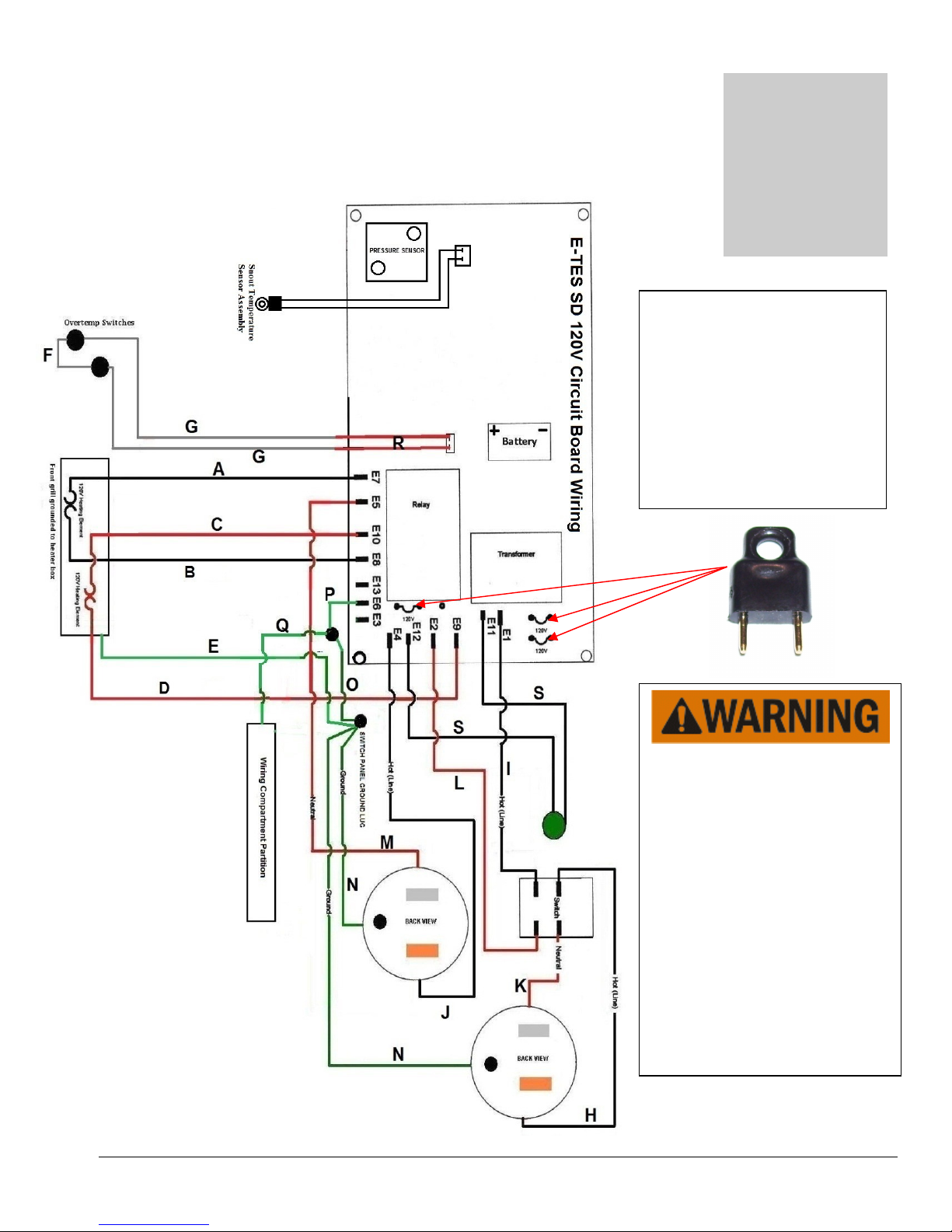
Se
ction
3
Heater Wiring
Copyright Tes Drying Systems, 2014
Three jumpers used to convert
circuit board for use with
120vac must be in the
positions shown for proper
operation of E-TES SD unit.
Circuit board may be damaged
if board is used with jumpers
in the wrong position
The battery used in this device
may present a fire or chemical
burn hazard if mistreated. Do
not recharge, disassemble, heat
above 100° C (212° F) or
incinerate. Replace battery with
Panasonic, Part Number BR2/3A only. Use of another
battery may present a risk of fire
or explosion.
Dispose of used battery
promptly. Keep away from
children. Do not disassemble
and do not dispose of in fire.
36
Page 37
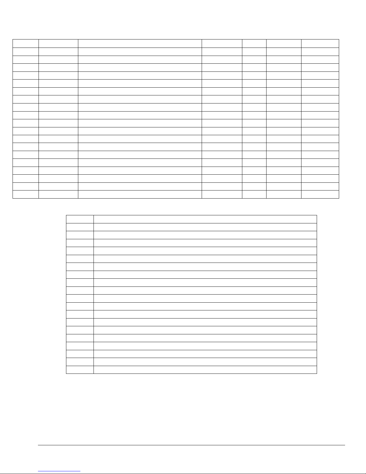
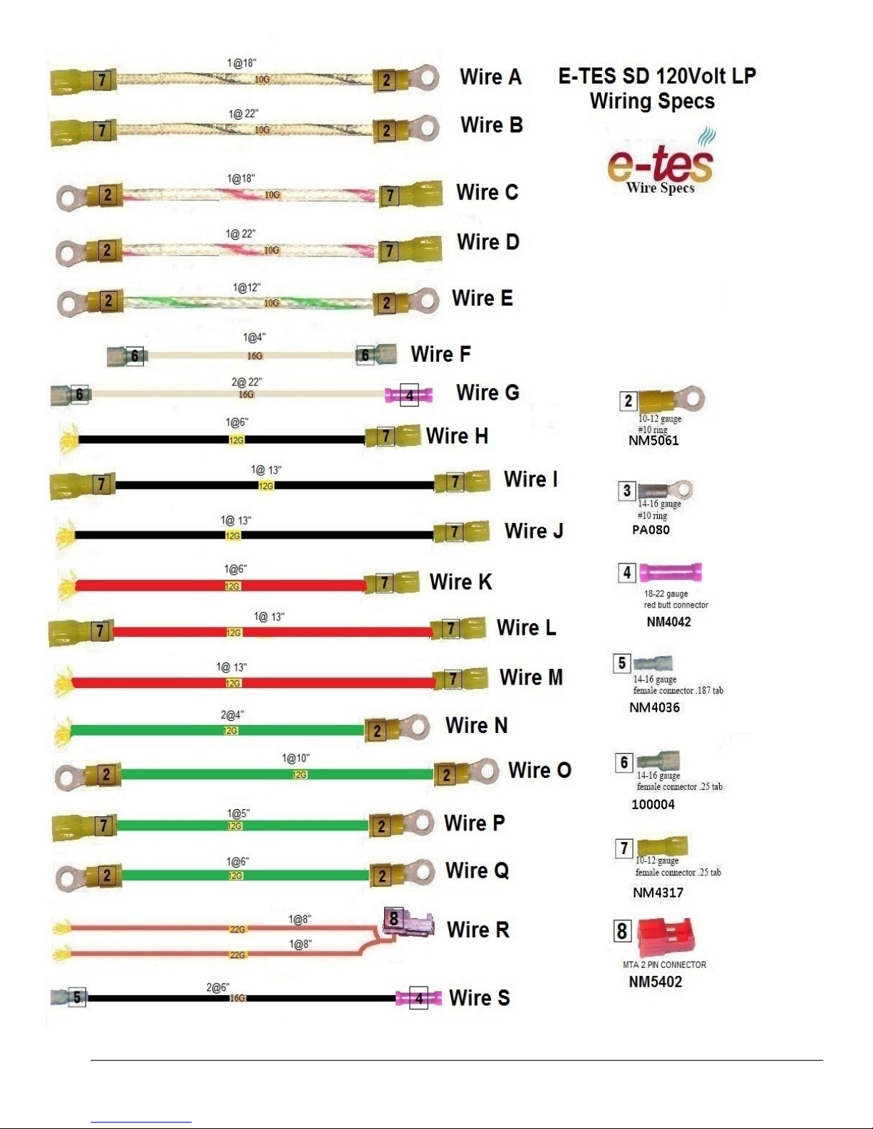
E-TES SD 120V LOW PROFILE WIRING
LIST#
PART #
DESCRIPTION
"
QTY
END #1
END #2
LIST#
NOTE
LENGTH
A NM4033B WIRE 10 GA HI-TEMP BLACK STRIPE 18.00 1 NM5061 NM4317
B NM4033B WIRE 10 GA HI-TEMP BLACK STRIPE 22.00 1 NM5061 NM4317
C NM4033R WIRE 10 GA HI-TEMP RED STRIPE 18.00 1 NM5061 NM4317
D NM4033R WIRE 10 GA HI-TEMP RED STRIPE 22.00 1 NM5061 NM4317
E NM4033G WIRE 10 GA HI-TEMP GREEN STRIPE 12.00 1 NM4037 NM5061
F NM5021HT WIRE 16 GA HI-TEMP 4.00 1 100004 100004
G NM5021HT WIRE 16 GA HI-TEMP 22.00 2 100004 NM4042
H NM5040 WIRE 12 GA BLACK 6.00 1 NONE NM4317
I NM5040 WIRE 12 GA BLACK 13.00 1 NM4317 NM4317
J NM5040 WIRE 12 GA BLACK 13.00 1 NONE NM4317
K NM5040A WIRE 12 GA RED 6.00 1 NONE NM4317
L NM5040A WIRE 12 GA RED 13.00 1 NM4317 NM4317
M NM5040A WIRE 12 GA RED 13.00 1 NONE NM4317
N NM5040B WIRE 12 GA GREEN 4.00 2 NONE NM5061
O NM5040B WIRE 12 GA GREEN 10.00 1 NM5061 NM5061
P NM5040B WIRE 12 GA GREEN 5.00 1 NM5061 NM4317
Q NM5040B WIRE 12 GA GREEN 6.00 1 NM5061 NM5061
R NM5404 WIRE 22GA RED 8.00 2 NONE NM5402
S PA175 WIRE 16GA BLACK 6.00 2 NM4036 NM4042
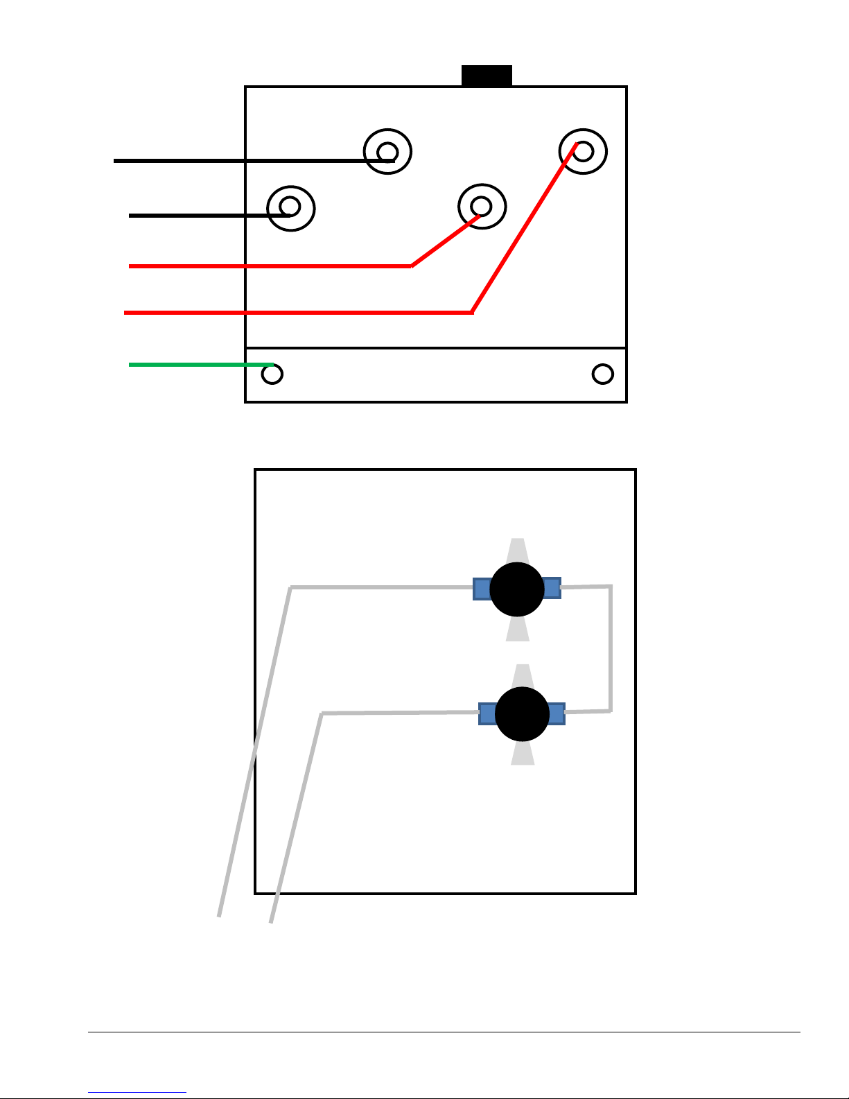
A HEATER #1 TO CIRCUIT BOARD E7
B HEATER #1 TO CIRCUIT BOARD E8
C HEATER #2 TO CIRCUIT BOARD E10
D HEATER #2 TO CIRCUIT BOARD E9
E HEATER TO SWITCH PANEL GROUND LUG
F TEMP SWITCH JUMPER
G TEMP SWITCH TO SPLICE W/ WIRE R
H PLUG 1 TO SWITCH
I SWITCH TO CIRCUIT BOARD E1
J PLUG 2 TO CIRCUIT BOARD E4
K PLUG 1 TO SWITCH
L SWITCH TO CIRCUIT BOARD E2
M PLUG 2 TO CIRCUIT BOARD E5
N PLUGS TO SWITCH PANEL GROUND LUG
O SWITCH PANEL GROUND LUG TO CONTROL PANEL GROUND LUG
P CONTROL PANEL GROUND LUG TO CIRCUIT BOARD E3
Q PARTITION TO CONTROL PANEL GROUND LUG
R BOTH WIRE CONNECT TO SINGLE NM5401 & SPLICE WITH BOTH WIRE G
S EXTEND GREEN LIGHT WIRES TO CIRCUIT BOARD (E11 & E12)
Copyright Tes Drying Systems, 2014
37
Page 38
Copyright Tes Drying Systems, 2014
38
Page 39
B
A
C
D
E
G
F
G
Copyright Tes Drying Systems, 2014
39
Page 40
Heater Maintenance
Section
4
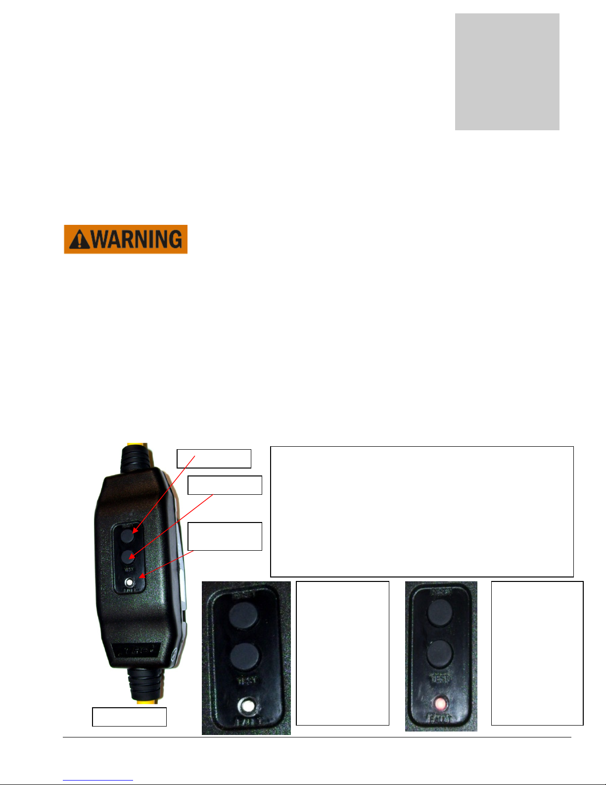
GFCI
RED
The E-TES SD 120 Volt Low Profile Electric Thermal Exchanger requires very little maintenance.
To keep this unit in
each time before using this equipment:
• Remove lint or debris that may be collecting on heating elements or inside E-TES SD unit.
• Examine wiring to ensure wiring to switches and heating elements is not damaged or worn. Check wire
connections to ensure that they are tight and have not worked loose due to vibration or other related
conditions. Repair or replace wires before using this equipment.
• Examine plastic E-TES SD 120 Volt Low Profile unit body for damage and repair or replace as needed.
• Check power cords for wear or damage and repair or replace as needed. Repair or replace worn or damaged
power cords before using this equipment.
•
Check Clock setting. If clock does not keep time & needs to be reset after turning the E-TES SD off and back
on, the battery should be replaced. Replace battery with Panasonic, Part Number BR-2/3A only.
• Clean sensor cord plug ends. Check sensor cords for wear or damage and repair or replace as needed.
• Test GFCI and replace cord if GFCI is not operating properly. Replace cord as needed.
RESET BUTTON
TEST BUTTON
FAULT LIGHT
safe
operating condition, perform the following inspections
When the GFCI cord is connected to the 120vac outlet, push the
RESET Button. Then, push the TEST button to test the GFCI.
• If RESET button pops out and red FAULT light turns ON,
push RESET button back in and proceed with your
equipment set-up.
• If RESET button does not pop out and red FAULT light
stays OFF when the TEST button is pushed, replace cord or
contact your nearest service center for advice or assistance.
RESET Button
in ON position
Red FAULT
Light OFF
Power is flowing
through the
GFCI to the
equipment
RESET Button
in OFF position
Red FAULT
Light ON
No power is
being supplied
to the
equipment
Copyright Tes Drying Systems, 2014
40
Page 41
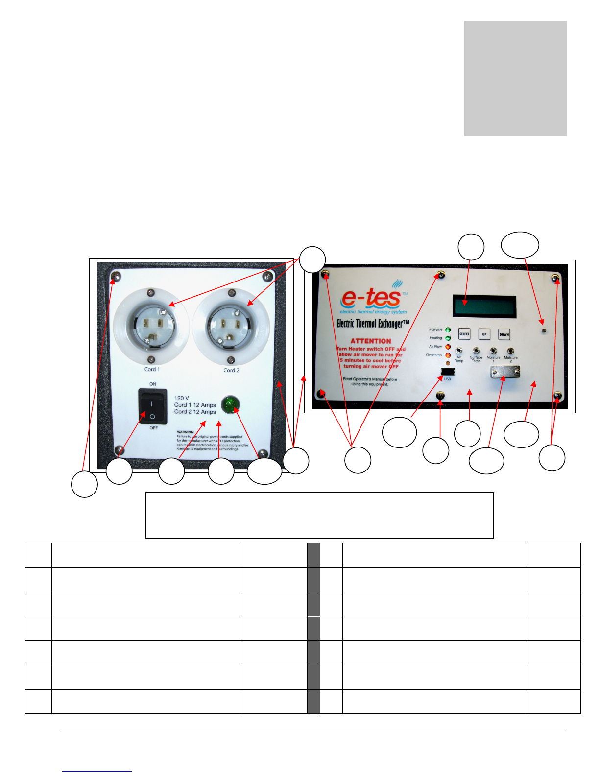
Parts
Section
4
1
2 3
1 FLANGED PLUG NEMA 5
-15P
NM4399
8 DECAL E
-
TES SD
NM5392B
2 ROCKER SWITCH DPST
NM5714
9 PANEL E
-
TES SD
LOW PROFILE
NM5908
3 DECAL E
-
TES SD 120
VOLT
NM
5392A
10 LIGHT DUAL CIRCUIT INDICATOR
NM4447
4 PANEL
E-
TES SD 12
0 VOLT
NM
5906 11
USB PORT DUST CAP
NM5384
5 SCREW 10
-
24 X 1/2” PHPH SS (QTY 10
)
NM5947
12 SERIAL PORT DUST CAP
NM5385
6 BODY TEX THERMAL EXCHANGER
–
NM590
1 NS SCREW 6
-
32 X .375” PPH SS (QTY 4)
NM5436
7 CIRCUIT BOARD E
-
TES SD
NM5394
A NS
WASHER #6 INTERNAL STAR (QTY 4)
NM5434
7
5
4
6
5
8
9
10
12
5
5
41
Replacement parts available for repair of your
ELECTRIC THERMAL EXCHANGER.
FRONT SWITCH PLATE AND CONTROL PANEL
E-TES SD 120 VOLT LOW PROFILE
E-TES SD 120V LOW PROFILE
11
(QTY 2)
LOW PROFILE SWITCH PANEL
LOW PROFILE SWITCH
(Attach switch panel & control panel)
LOW PROFILE PLASTIC
Copyright Tes Drying Systems, 2014
LOW PROFILE CONTROL PANEL
CONTROL
GREEN 120V NEON
(Attach circuit board to panel)
(Attach circuit board to panel)
41
Page 42
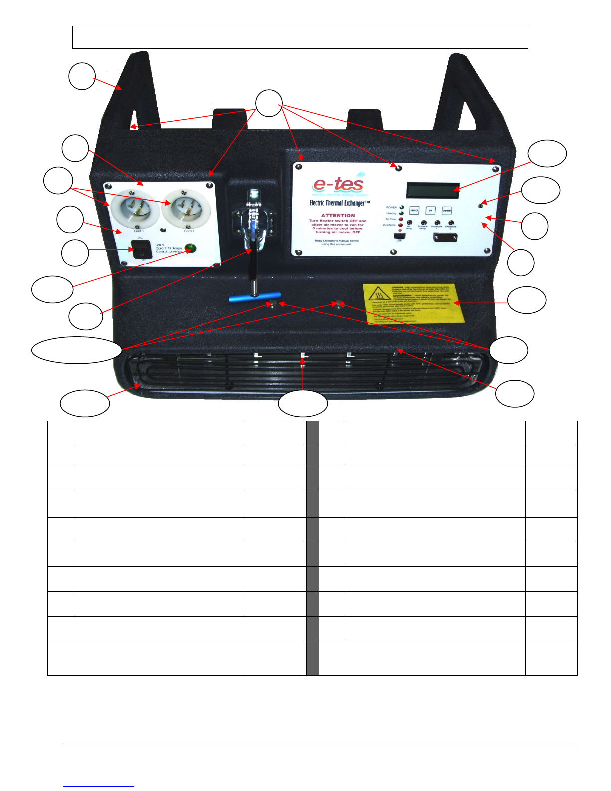
E-TES LOW PROFILE
FRONT VIEW OF
COMPONENTS
1 FLANGED PLUG NEMA 5
-15P
NM4
399 13
SCREW ¼
-
20 X 3/4
” HXHD SS
(QTY 2)
NM
5017
2 ROCKER SWITCH DPST
NM5
714 14
FLAT WASHER ¼” SS
(QTY 2)
NM5066
3 DECAL E
-
TES SD 12
0 VOLT
NM5392A
14A LOCK
WASHER ¼” SS
(QTY 2)
NM
5014
4 PANEL E
-
TES SD 12
0 VOLT
NM5906
15A HEATER BOX BOTTOM E
-
TES LP
SEE
5 SCREW 10
-
24 X ½” PHP SS (QTY 10)
NM5947
15B HEATER BOX TOP E
-
TES LP
SEE PAGE
6 BODY
E-TES LOW PROFILE
NM590
1 16
FRONT GRILLE
E-
TES LOW
NM5932
7 CIRCUIT BOARD E
-
TES SD
NM5394
A 17
CLAMP ASSEMBLY
SEE PAGE
8 DECAL E
-
TES SD
NM5392B
41 BARB 3/32” X 10
-
32 THREAD POLY
NM5914
9 PANEL E
-
TES SD
LOW PROFILE
NM5908
51 DECAL HEATER WARNING
NM4437C
10 LIGHT DUAL CIRCUIT
NM4447
NS SCREW 8
-
32 X ½” PHP SS (QTY 4)
NM5124
6
9
5
3
4
8
17
15A
16
1
2
7
13
10
15B
41
14 & 14A
51
(QTY 2)
LOW PROFILE SWITCH PANEL
(Attach Heater Box to Body)
(Attach Heater Box to Body)
(Attach Heater Box to Body)
LOW PROFILE SWITCH
(Attach switch panel & control panel)
PAGES
45 & 48
48
EXCHANGER
PROFILE
43
LOW PROFILE CONTROL PANEL
CONTROL
KIT PART 2 OF 2
INDICATOR
GREEN 120V NEON
(Attach heater box top & bottom)
Copyright Tes Drying Systems, 2014
42
Page 43
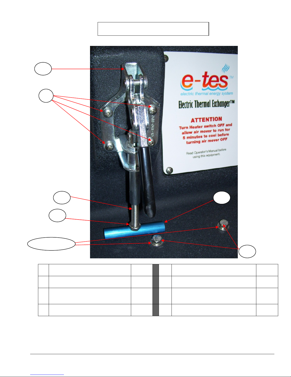
1 CLAMP TOGGLE
NM4245
7 FLAT WASHER ¼” SS
2 STUD 5/16
-
18 X 2”
NM4246
8 SCREW 10
-
32 X 7/8” BHCS SS
NM4240
3 NUT 5/16
-
18 HEX (Qty 2)
NM4290
9 NUT 10
-
32 NYLOCK SS
NM4081
4 BAR CARPET CLAMP ½” X 3”
NM4247
NS BRACKET SN
OUT SUPPORT TEX
5 PLATE CARPET CLAMP
NS
NUT 1/4
-
20 HEX NYLOCK SS
6 SCREW ¼
-
20 X 1” HXHD SS
NS
SCREW 1/4
-
20 x 1/2” PH FTHD SS
18
19
20
5
13
13
1 CLAMP TOGGLE
NM4245
7 FLAT WASHER ¼” SS
2 STUD 5/16
-
18 X 2”
NM4246
8 SCREW 10
-
32 X 7/8” BHCS SS
NM4240
3 NUT 5/16
-
18 HEX (Qty 2)
NM4290
9 NUT 10
-
32 NYLOCK SS
NM40
81
4 BAR CARPET CLAMP ½” X 3”
NM4247
NS BRACKET SNOUT SUPPORT TEX
5 PLATE CARPET CLAMP
NS
NUT 1/4
-
20 HEX NYLOCK SS
6 SCREW ¼
-
20 X 1” HXHD SS
NS
SCREW 1/4
-
20 x 1/2” PH FTHD SS
1 CLAMP TOGGLE
NM4245
14A LOCK
WASHER ¼” SS
(QTY 2)
NM
5014
5 SCREW 10
-
24 X 1/2” PHP
SS
(QTY 4)
NM5947
18 STUD 5/16
-
18 X 2
-
1/2” NM4246
13 SCREW ¼
-
20 X 3/4
” HXHD SS
(QTY
NM
5017 19
NUT 5/16
-
18 HEX
NM4290
14 FLAT WASHER ¼”
SS (QTY 2)
NM5066
20 BAR CARPET CLAMP ½” X 3”
NM4247
14 & 14A
CARPET CLAMP ASSEMBLY
(Attach carpet clamp to box)
2)
(Secure heater box assembly)
(Secure heater box assembly)
Copyright Tes Drying Systems, 2014
(Attach Heater Box to Body)
43
Page 44
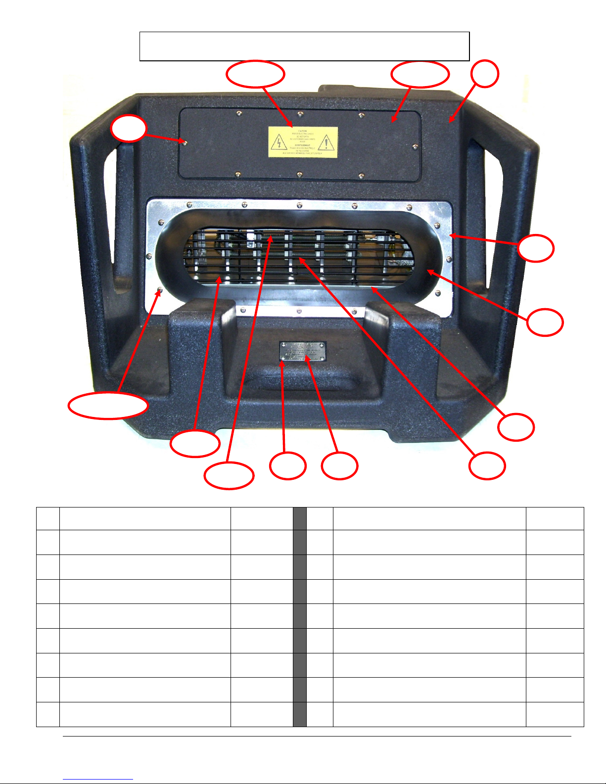
6 BODY
E-TES LOW PROFILE
NM590
1 25
HEATER BOX E
-
TES LP
SEE PAGES
6A BACK ACCESS PLATE E
-
TES LP
NOT SOLD
25A HEATER BOX E
-
TES LP
SEE PAGE
5 SCREW 10
-
24 X ½” P
HP SS (QTY 8)
NM5947
NS
SCREW 8
-
32 X 1/2” PHP SS (QTY 4)
NM5124
14 FRONT GRILLE
E-
TES LOW
NM5932
51 DECAL ELECTRICAL WARNING
NM4437C
20 GASKET
E-TES LOW PROFILE
NM5936
52 SERIAL NUMBER PLATE
NM5572
21
GASKET RETAINER E
-
TES LP
NM5937
53 RIVET 1/8” ALUMINUM (QTY 4)
NS116
22 SCREW 10
-
24 X 3/4
” PPH SS
(QTY 16)
NM4244
23 NUT 10
-
24 NYLOCK SS (QTY 16)
PHY094
-
034 NS
SCREW #8 X ½” SELFTAP SS PH
NM4372
24 INSULATION CERAMIC PAPER
NM4441A
NS WIRING COMPARTMENT PARTITION
NM5934
20
6A
21
E-TES LOW PROFILE
BACK VIEW OF
COMPONENTS
6
22 & 23
24
14
25
5
25A
51
52 53
EXCHANGER (Includes #6A)
PROFILE
SEPARATELY
(BOTTOM)
(TOP)
(Attach top to box bottom)
KIT PART 1 OF 2
45 - 48
48
Copyright Tes Drying Systems, 2014
(Attach serial number plate)
(QTY4) (Attach wiring compartment partition)
44
Page 45
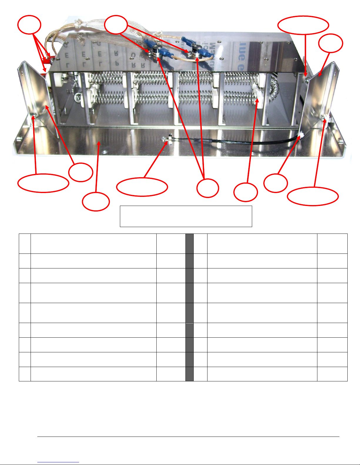
25
25 HEATER BOX
- BOTTOM
NM5916
36 WIRE TIE 4” WHITE
NM5418
28 SCREW 8
-
32 X ½” PHP SS
NM5124
37 CAP THREAD PROTECTOR#8 RED
NM5923
27 NUT 8
-
32 NYLOCK SS
NM5793
45 SNOUT TEMP SENSOR ASSEMBLY
NM5394B
28 SCREW 8
-
32 X 5/8” PHP SS
NM5723
46 RIVET 1/8”
NS116
27 NUT 8
-
32 NYLOCK SS
NM5793
NS W
IRE SLEEVE 5/8” ( 1 PIECE 6” )
NM5420
29 BRACKET AIR FLOW GUIDE
NM5917
NS WIRE SLEEVE 7/16” (1 PIECE 6”)
NM5421
30 SWITCH 210F TEMP SNAP SWITCH
NM5930
NS WIRE TIE 7” BLACK
100003
31 SCREW #8 X 1/2” PPH SS SELF TAP (QTY 4)
NM4372
NS WIRE TIE 4” WHITE
NM5418
32 HEATER COIL ASSEMBLY 3000W 12
0V
NM5920
28 & 27
29
30
31
32
28 & 27
28 & 27
29
45 & 46
36
31
Heater Assembly – E-TES SD 120 Volt LP
(AIR FLOW GUIDE BRACKET MOUNT)
(AIR FLOW GUIDE BRACKET MOUNT)
(ATTACH HEATER COIL ASSY TO BOTTOM
BOX)
(ATTACH HEATER COIL ASSY TO BOTTOM
BOX)
(Attach temp switches)
Front side view – TOP OFF
(Secure Snout Temp Sensor Assembly away
from heater)
(Qty 4)
(ATTACH SNOUT TEMP SENSOR)
(Secure 5/8” wire sleeve)
(Secure 7/16” wire sleeve)
Copyright Tes Drying Systems, 2014
45
Page 46
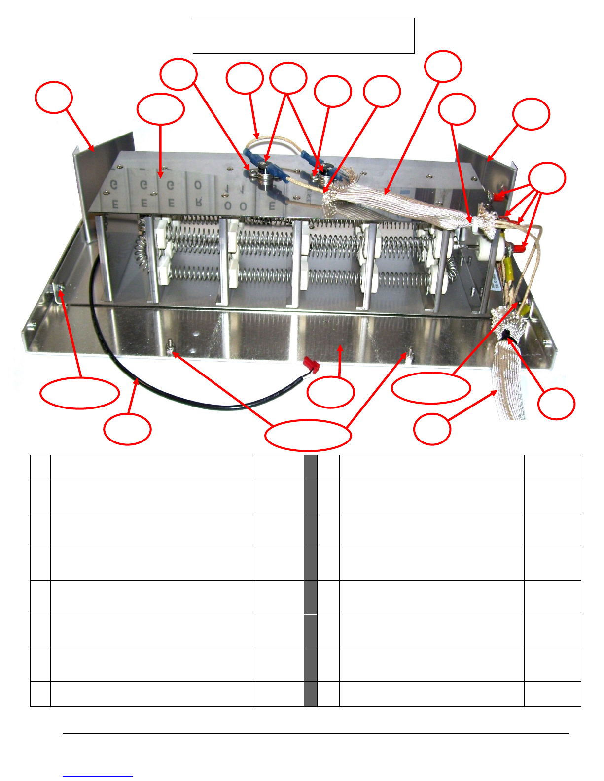
25
25 HEATER BOX
- BOTTOM
NM5916
32 HEATER COIL ASSEMBLY 3000W 120V
NM5920
26 SCREW 8
-
32 X ½” PHP SS
NM5124
33 WIRE SLEEVE 5/8” ( 1 PIECE 6” )
NM5420
27 NUT 8
-
32 NYLOCK SS
NM5793
34 WIRE SLEEVE 7/16” (1 PIECE 6”)
NM5421
28 SCREW 8
-
32 X 5/8” PHP SS
NM5723
35 WIRE TIE 7” BLACK
100003
27 NUT 8
-
32 NYLOCK SS
NM5793
36 WIRE TIE 4” WHITE
NM5418
29 BRACKET AIR FLOW GUIDE
NM5719
F WIRE TEMP SWITCH JUMPER
SEE
30 SWITCH 210F TEMP SNAP SWITCH
NM5930
G WIRE TEMP SWITCH TO CIRCUIT
SEE
31 SCREW #8 X 1/2” PPH SS SELF TAP
(QTY 4)
NM
4372 45
SNOUT TEMP SENSOR ASSEMBLY
NM5
394B
28 & 27
31
31
29
28 & 27
26 & 27
34
35
32
F
G
45
37
33
36
30
29
Heater Assembly – E-TES SD 120 Volt LP
Back side view – TOP OFF
(BOTTOM MOUNTING PEGS FOR REAR
GRILL)
(BOTTOM MOUNTING PEGS FOR REAR
GRILL)
(ATTACH HEATER COIL ASSY TO
BOTTOM BOX)
(ATTACH HEATER COIL ASSY TO
BOTTOM BOX)
(Secure 5/8” wire sleeve)
(Secure 7/16” wire sleeve)
(Attach temp switches)
Copyright Tes Drying Systems, 2014
46
16GA HI-TEMP
BOARD - 16GA HI-TEMP
WIRING
DIAGRAM
WIRING
DIAGRAM
Page 47
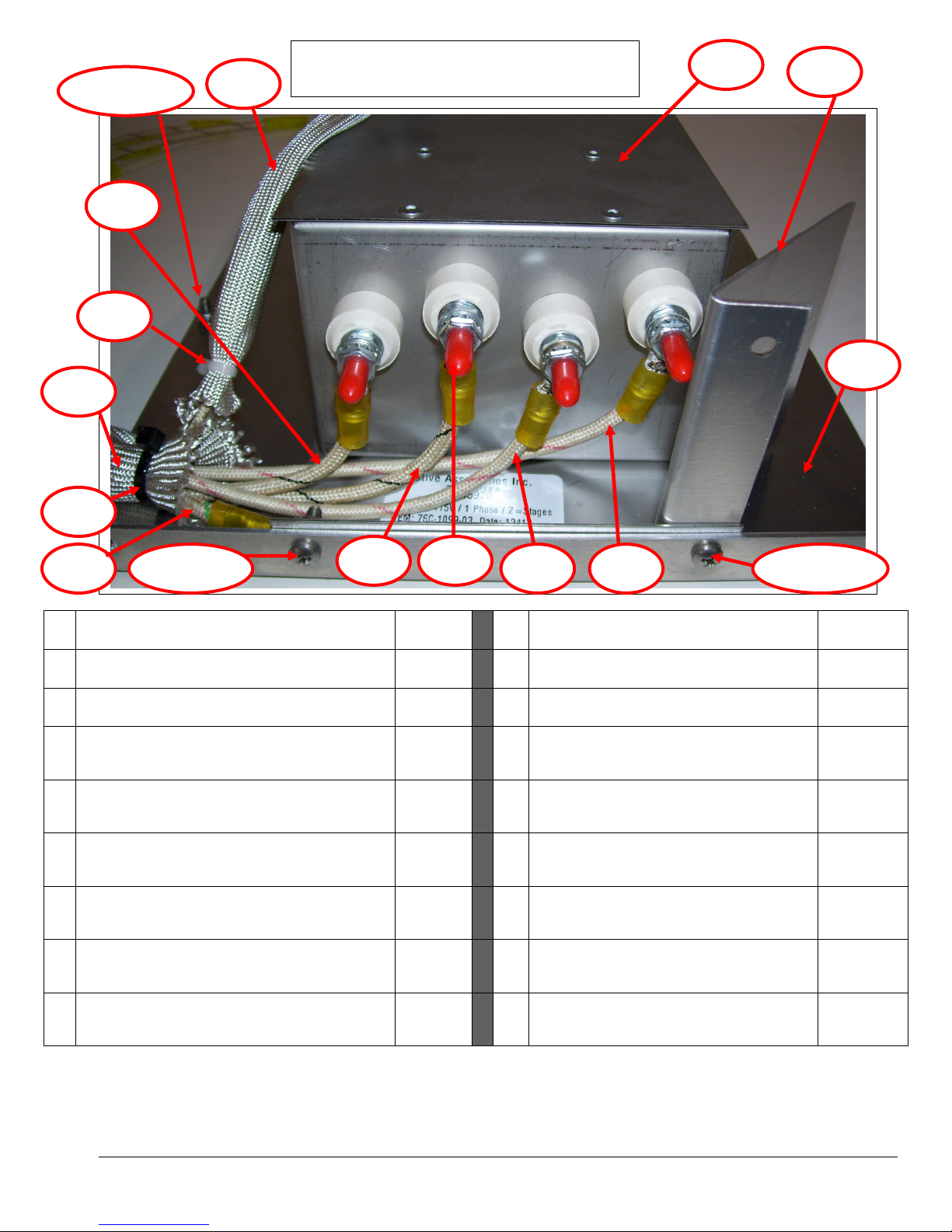
25 HEATER BOX
- BOTTOM
NM5916
35 WIRE TIE 7” BLACK
100003
26 SCREW 8
-
32 X ½” PHP SS
NM5124
36 WIRE TIE 4” WHITE
NM5418
27 NUT 8
-
32 NYLOCK SS
NM5793
37 CAP THREAD PROTECTOR#8 RED
NM5923
28 SCREW 8
-
32 X 5/8” PHP SS
NM5723
27 NUT 8
-
32 NYLOCK SS
NM579
3 A
WIRE CIRCUIT BOARD TO HEATER
SEE
29 BRACKET AIR FLOW GUIDE
NM5719
B WIRE CIRCUIT BOARD TO HEATER
SEE
32 HEATER COIL ASSEMBLY 3000W 120V
NM5920
C WIRE CIRCUIT BOARD
TO HEATER
SEE
33 WIRE SLEEVE 5/8” ( 1 PIECE 6” )
NM5420
D WIRE CIRCUIT BOARD TO HEATER
SEE
34 WIRE SLEEVE 7/16” (1 PIECE 6”)
NM5421
E WIRE HEATER GROUND
SEE
25
26 & 27
28 & 27
29
32
A
E C D 28
& 27
33
35
34
B
36
37
Heater Assembly – E-TES SD 120 Volt LP
TOP OFF -Side view
(BOTTOM PEGS FOR REAR GRILL)
(BOTTOM PEGS FOR REAR GRILL)
(ATTACH HEATER COIL ASSY TO
BOTTOM BOX & AIR GUIDE MOUNT)
(ATTACH HEATER COIL ASSY TO
BOTTOM BOX & AIR GUIDE MOUNT)
(Secure 5/8” wire sleeve)
(Secure 7/16” wire sleeve)
(Qty 4)
BLACK STRIPE 10GA HI-TEMP
WIRING
DIAGRAM
BLACK STRIPE 10GA HI-TEMP
Copyright Tes Drying Systems, 2014
47
RED STRIPE 10GA HI-TEMP
RED STRIPE 10GA HI-TEMP
GREEN STRIPE 10GA HI-TEMP
WIRING
DIAGRAM
WIRING
DIAGRAM
WIRING
DIAGRAM
WIRING
DIAGRAM
Page 48
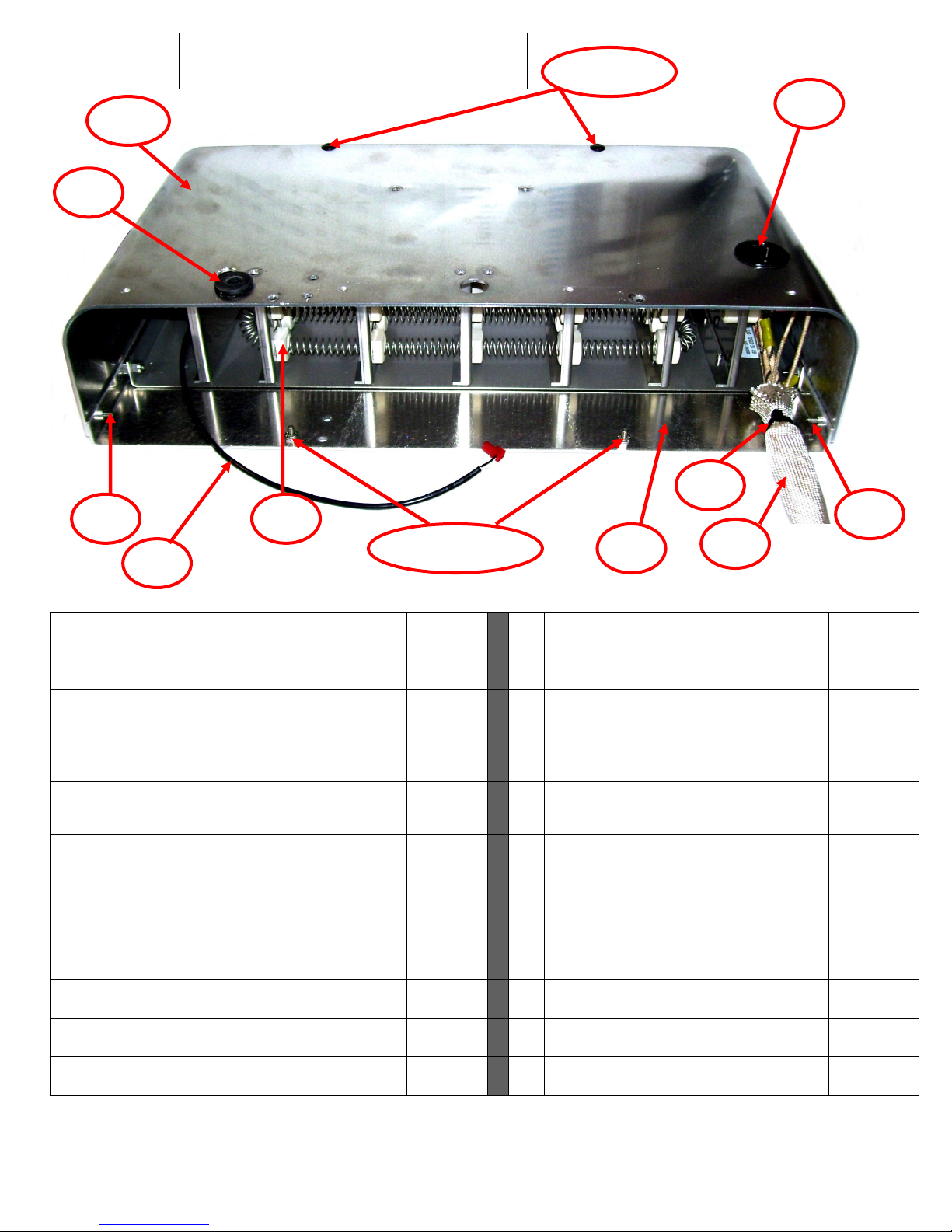
25A HEATER BOX
- TOP NM5916B
36 WIRE TIE 4” WHITE
NM5418
25 HEATER BOX
- BOTTOM
NM5916 37
BUSHING SNAP
-
IN WIRE GUARD
NM5445
26 SCREW 8
-
32 X ½” PHP SS
NM5124
38 RIVET 3/16” SPLIT TYPE
NM5099
26 SCREW 8
-
32 X ½” PHP SS
NM5
124 39
WASHER 3/16” PAINT PIERCING
NM5933
27 NUT 8
-
32 NYLOCK SS
NM5793
45 SNOUT TEMP SENSOR ASSEMBLY
NM5
394B
28 SCREW 8
-
32 X 5/8” PHP SS
NM5723
47 GROMMET
NM4116
27 NUT 8
-
32 NYLOCK SS
NM5793
NS RIVET 3/16” SPLIT TYPE
NM5099
32 HEATER COIL ASS
EMBLY 3000W 120V
NM5920
NS WASHER 3/16” PAINT PIERCING
NM5933
33 WIRE SLEEVE 5/8” ( 1 PIECE 6” )
NM5420
NS GRILL
NM5932
34 WIRE SLEEVE 7/16” (1 PIECE 6”)
NM5421
NS AIR PRESSURE HOSE BRACKET ASSY
35 WIRE TIE 7” BLACK
100003
NS RIVET 3/16” X 1/2” ALUM
(QTY 2)
NM4288
25A
25
26
26 & 27
38 & 39
32
35
33
37
26
45
47
(ATTACH HEATER BOX TOP & BOTTOM)
(BOTTOM MOUNTING PEGS FOR REAR
GRILL)
(BOTTOM MOUNTING PEGS FOR REAR
GRILL)
(ATTACH HEATER COIL ASSY TO
BOTTOM BOX & AIR GUIDE MOUNT)
(ATTACH HEATER COIL ASSY TO
BOTTOM BOX & AIR GUIDE MOUNT)
(Secure 5/8” wire sleeve)
Heater Assembly – E-TES SD 120 Volt LP
TOP ON -Rear view
(Secure 7/16” wire sleeve)
(Front Grill Mount– 2 top & 2 bottom)
(Front Grill Mount– 2 top & 2 bottom)
(Protects tubing through heater box top)
(Rear Grill Mount– 2 top)
(Rear Grill Mount– 2 top)
(One in front & one in rear)
(Mounts to heater box top)
(Secure Air Pressure Hose Bracket)
Copyright Tes Drying Systems, 2014
48
Page 49
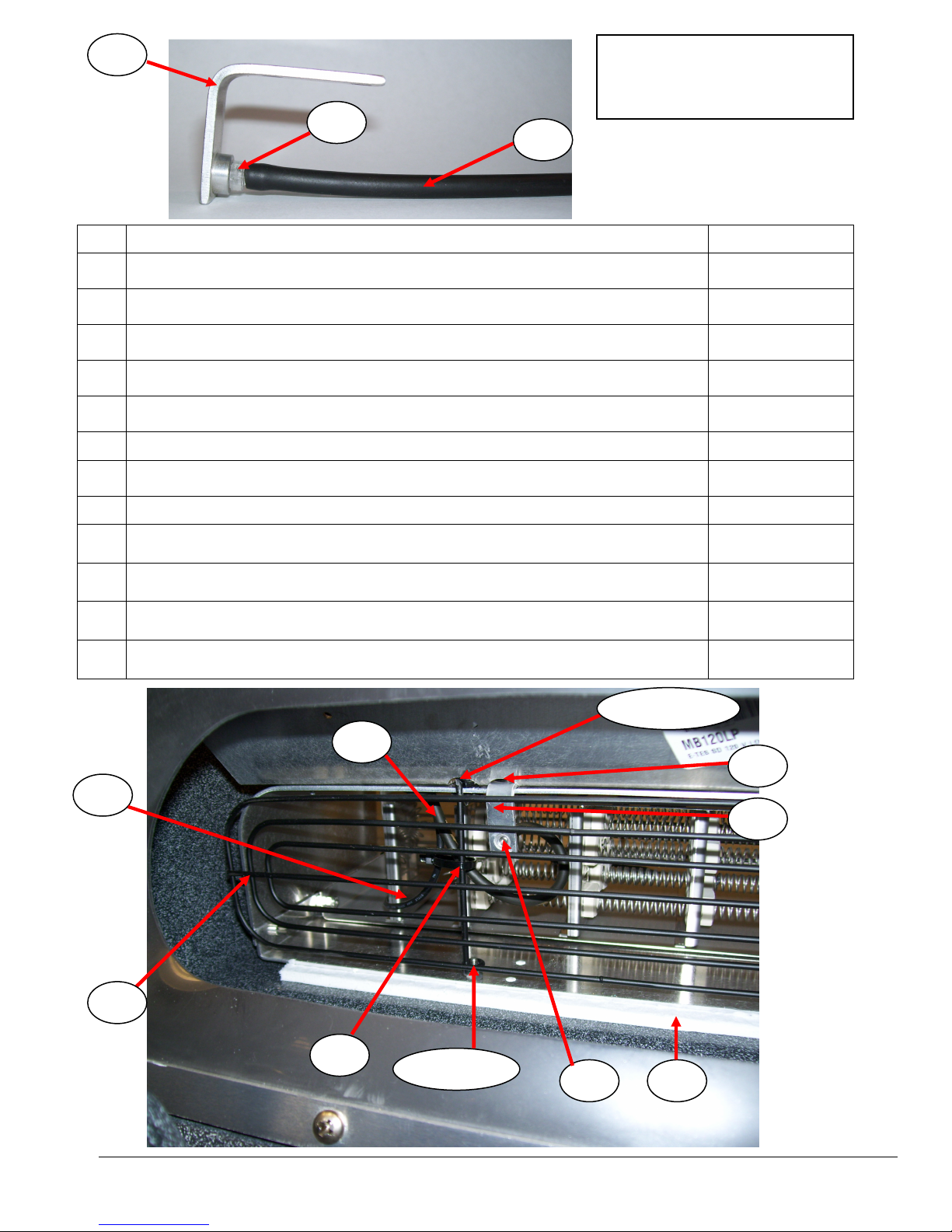
41
40
42
41
42
35
40
38
44
26 & 2
7
24
24 INSULATION CERAMIC PAP
ER NM4441A
26 SCREW 8
-
32 X ½” PHP SS
NM5124
27 NUT 8
-
32 NYLOCK SS
NM5793
35 WIRE TIE 7” BLACK
100003
38 RIVET 3/16” SPLIT TYPE
NM5099
39 WASHER 3/16” PAINT PIERCING
NM5933
40 AIR PRESSURE HOSE BRACKET
NM5913
38 RIVET 3/16” SPLIT TYPE
NM5099
41 BARB 3/32” X 10
-32
THREAD POLY
NM5914
42 TUBING 3/32” ID SOLD PER INCH (12”)
NM5914B
44 GRILL
NM5932
45 SNOUT TEMP SENSOR ASSEMBLY
NM5394B
NS GROMMET
NM4116
45
38 & 39
(Bottom mounting pegs for rear grill)
(Bottom mounting pegs for rear grill)
(Secure tubing & snout sensor wire to grill)
(Rear Grill Mount– 2 top on top only)
(Rear Grill Mount– 2 top on top only)
(Air Pressure Hose Bracket Mount– Qty 2)
AIR PRESSURE HOSE
BRACKET ASSEMBLY
And REAR GRILL
(One in front & one in rear)
(Protects tubing through Heater Box Top)
Copyright Tes Drying Systems, 2014
49
Page 50
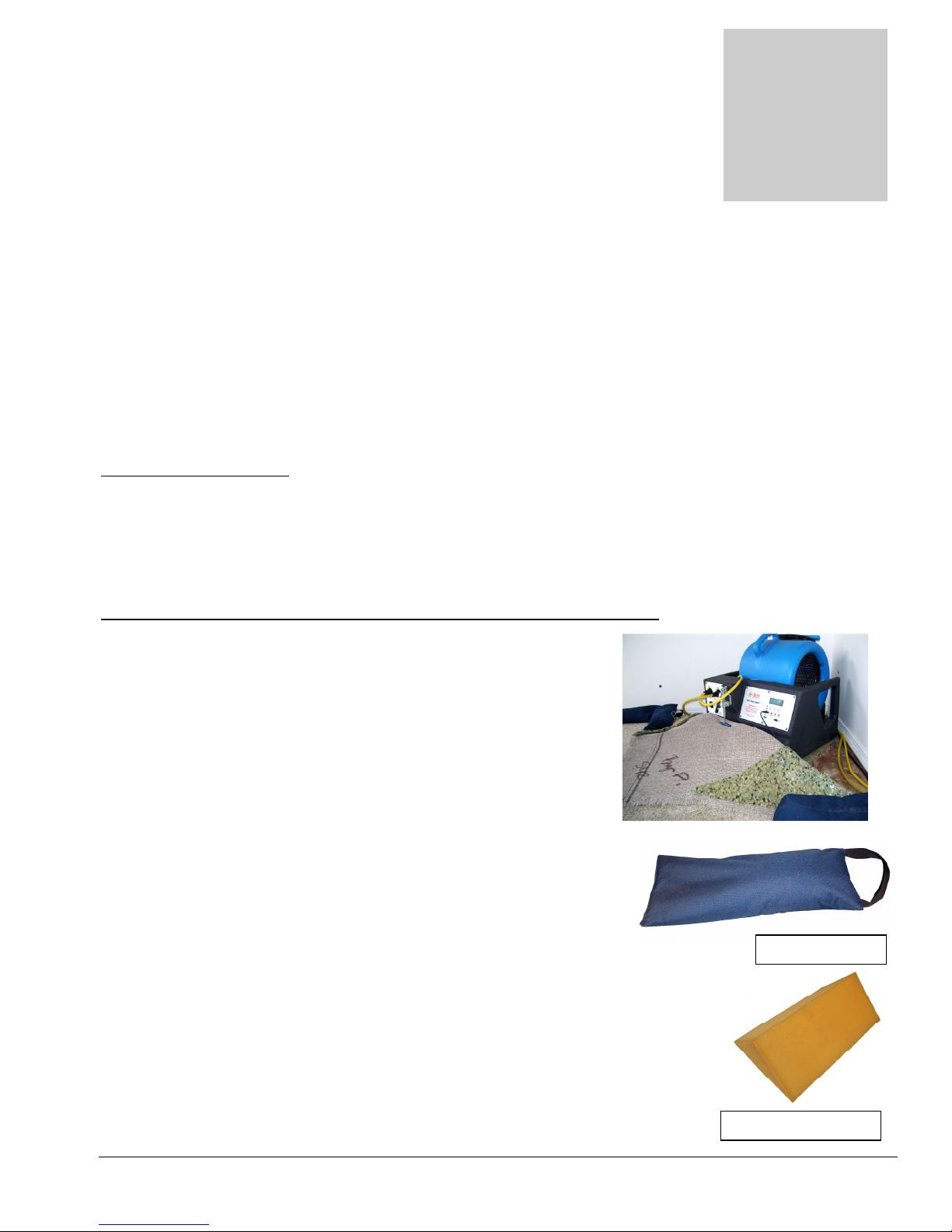
Heater Set-up Procedures
Section
5
SAND BAG
FOAM FILLER
The best way to dry wet carpet, hardwood floors and walls is to implement the Reets Evaporation Method
utilizing your E-TES SD unit. The following steps will explain how to this method can be applied for drying
different surfaces.
Carpet Drying
Step #1 – Extraction
1. This is the key for any drying. Extract as much of the water as possible with your portable or truck
mounted equipment. A weighted extraction tool will compress the padding and carpet to remove more
water. The more you remove with extraction, the faster the carpet will dry. Test extraction by squeezing
the pad in your hand. Continue extracting until no more water can be squeezed out. If this level of
extraction cannot be achieved, remove the pad.
Step #2 - Energy applied directly to the water
To contain the heat and apply the energy (heat) to the carpet and
floor:
1. Set the snout of the E-TES SD unit under the carpet to create a
“soft float”.
2. Pull up one corner of the carpet in the wet area and set the E-
TES SD unit in the corner, on top of the pad. Larger rooms
may require additional E-TES SD units. Leave 3-6 inches
between the back of the E-TES SD box and the wall.
3. Pull the carpet up over the snout and secure the carpet to the E-
TES SD unit with the carpet clamp. Then pull the E-TES SD
back toward the wall to pull the carpet tight. Pulling the carpet
tight will eliminate or reduce carpet flapping during the float.
4. Now place the one or two 10 lb. sandbags on the carpet, along the
wall, on each side of the unit to hold down the carpet and prevent
it from pulling off of the tack strip.
5. Cut the pad on each side of the E-TES SD unit and fold the pad
up on top of the carpet. This will help seal the space between the
carpet and the floor on each side of the E-TES SD unit to reduce air escaping.
Secure the pad to the carpet with pad pins or use Foam Filler to make a good
seal. A good seal will increase the amount of heated air flowing under the
carpet and improve the float.
Procedure
(Temperature)
Copyright Tes Drying Systems, 2014
50
Page 51
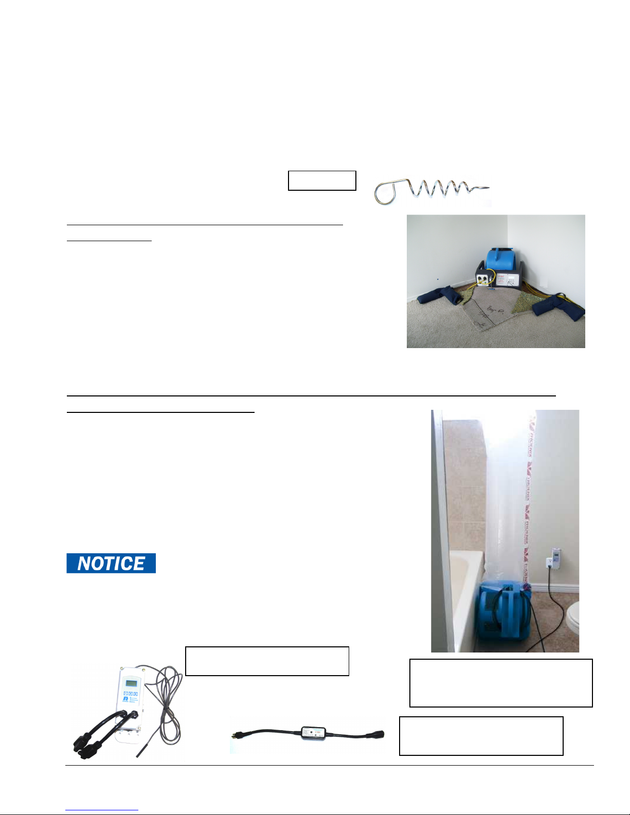
6. Insert a centrifugal air mover into the E-TES SD box. Plug the air mover cord into the wall outlet.
Air mover with ducting
Controller
PAD PIN
Exhaust Controller
MB230
Remote Exhaust Fan
Connect the two GFCI power cords to the E-TES SD 120 Volt unit and plug the cords into two different
120v circuit outlets.
7. Place remote sensors for air temperature, surface temperature and moisture level as needed in desired
locations. Connect the sensors to the E-TES SD 120 Volt unit.
8. Turn on the E-TES SD unit and adjust the set points for each of the remote sensors as required for your
application.
9. Turn on the air mover.
10. Adjust the speed of the air mover, use additional sand bags to hold the carpet down in some spots and
pad pins to lift the carpet in some areas as needed to get the carpet floating and prevent flapping.
Step #3 - Airflow applied directly to the water
(Evaporation)
1. We are getting air movement with the air mover and the E-
TES SD box is providing the heat. We are heating the water to
cause the evaporation, and removing the vapor from the floor
by providing airflow under and through the carpet. This heated
air heats the carpet, walls, baseboards, sill plates and walls up to
12”, that may also be wet, creating water vapor. As the air
escapes through the carpet and along the walls opposite the ETES SD unit, it carries the water vapor away from the wet
surfaces.
Step #4 - Reduction of vapor saturation levels (
evacuation
1. As we have evaporated the moisture into the air, we need to remove
it from the structure along with the excess heat. This is
accomplished with the exhaust controller, an air mover, 14” lay flat
duct and a duct ring. Set up the exhaust system to evacuate to the
outside of the structure.
2.
Set the Remote Activation temperature to turn on the exhaust fan
using the Smart E-TES Remote Exhaust Fan Control or use a
separate exhaust control unit set to keep the ambient room
temperature below 105ºF. (See Page 16 of this manual or the
instructions included with separate exhaust controller unit).
(Dehumidification)
humidity
) by dehumidification or
Overheating the structure may cause damage to
structure or contents. Controlling the temperature is important to
prevent damage.
Monitor your progress at least daily – more often if practical. Carpets,
floors and walls will dry quickly!
Copyright Tes Drying Systems, 2014
connected to Exhaust
Control AT206
51
Page 52
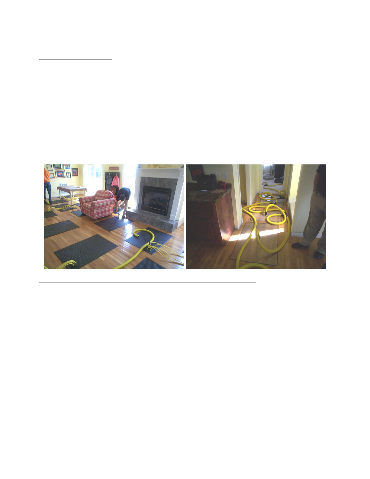
Wood Floor Drying
Procedure
Step #1 – Extraction
1. This is the key for any drying and especially for wood floor drying. Extract the pooled water on top of
the wood with your portable or truck mounted equipment. Use a squeegee type wand. A carpet wand
may scratch the floor’s finish.
2. You can also use a mop or towels. The more you remove this way, the faster it will dry.
3. Now what about the water between or under the boards? Many times there is still a substantial amount
of “free” water that can be extracted to speed up the drying. To remove that water, you need to use a
floor drying panel system. Place the panels on the floor and attach the hoses in the position the system
will be running; however, before you attach your blower unit, attach it to your extraction unit. Let this
run for up to 30 minutes or as long as you can. Pull up each panel and, using a towel, wipe up the excess
water that will have been drawn out of the floor system. Depending on the amount of water, you may
wish to repeat that step. You will be amazed at the amount of extra water you can remove this way.
4. Now reposition your panels and tape them as needed. Attach your blower and start the system.
Step #2 - Energy applied directly to the water
(Temperature)
1. Set up the wood floor drying panels and attach to the vacuum unit that was designed for this application.
2. Direct containment is the best way to apply the energy (heat) to the floor. Spread poly sheeting (4-6 mil)
over the affected floor and cut slightly larger than the area.
3. Now place the 10 lb. sandbags around the perimeter every 3 – 4 feet or as needed to hold the poly
sheeting down. You may even utilize any furniture in the room along the edges to hold the sheeting.
4. Place the snout of the E-TES SD under the sheeting and secure it with the clamp.
5. Place remote sensors for air temperature, surface temperature and moisture level as needed in desired
locations. Connect the sensors to the E-TES SD.
6. Insert a centrifugal air mover into the E-TES SD box. Connect the power cord to the E-TES SD and
plug in the E-TES SD and air mover cords.
7. Turn on the air mover and the E-TES SD unit.
8. Adjust the set points for each of the remote sensors as required for your application.
9. If you have a crawlspace to place an E-TES SD or can direct more heated airflow below the floor, it will
aid in the drying process.
10. It is important that the blower for the floor drying panel system be placed outside the direct containment
(i.e. NOT under the poly sheeting).
Copyright Tes Drying Systems, 2014
52
Page 53
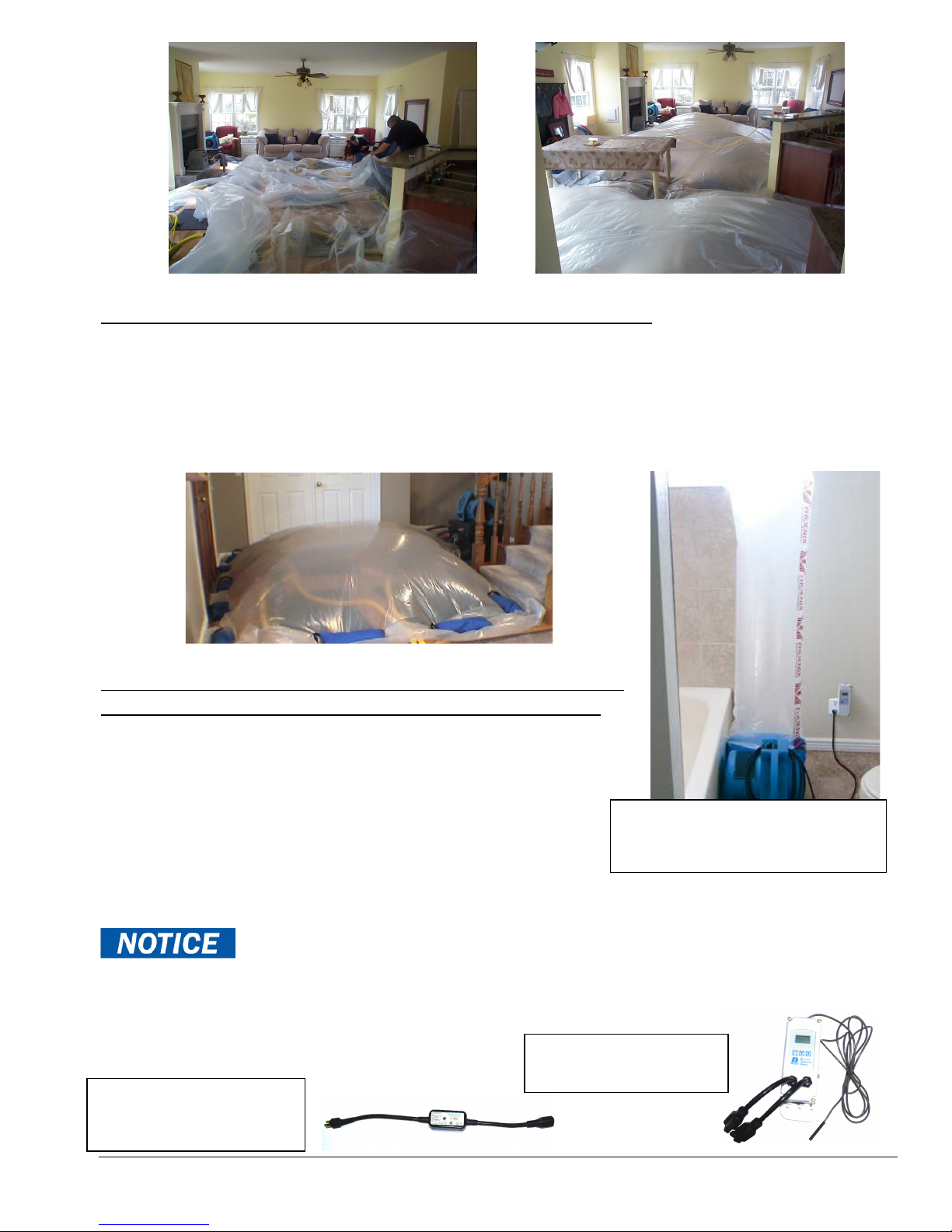
Air mover with ducting
Controller
Smart E
-
TES Remote
AT206
Exhaust C
ontroller
Step #3 - Airflow applied directly to the water
(Evaporation)
1. We are getting air movement with two pieces of equipment – the air mover / E-TES SD box and also the
floor drying panel system. We are heating the water to cause the evaporation, but the floor drying panel
system is removing the vapor from the floor by providing airflow through the interspatial cavities in the
floor.
2. The sandbags – rather than stapling/taping/sealing – allows the air to escape bringing with it water vapor
and heating the walls, baseboards and sill plates that may also be affected.
Step #4 - Reduction of vapor saturation levels (
by dehumidification or evacuation
(Dehumidification)
humidity
)
1. Now that we have evaporated the moisture into the air, we need
to remove it from the structure along with the excess heat. This
is accomplished with the exhaust controller, an air mover, 14”
lay flat duct and a duct ring. Set up the exhaust system to
evacuate to the outside of the structure.
2.
Set the Remote Activation temperature to turn on the
connected to Exhaust
exhaust fan using the Smart E-TES Remote Exhaust Fan
Control or use a separate exhaust control unit set to keep
the ambient room temperature below 105ºF. (See Page 16 of this manual or the instructions included
with separate exhaust controller unit).
Overheating the structure may cause damage to structure or contents.
Controlling the temperature is important to prevent damage.
Since there is less water in the wood than would be in a carpet/pad combination, the exhaust doesn’t need to
cycle as often. Monitor your progress at least daily – more often if practical.
Floors will dry quickly!
Exhaust Controller
Copyright Tes Drying Systems, 2014
MB230
53
Page 54
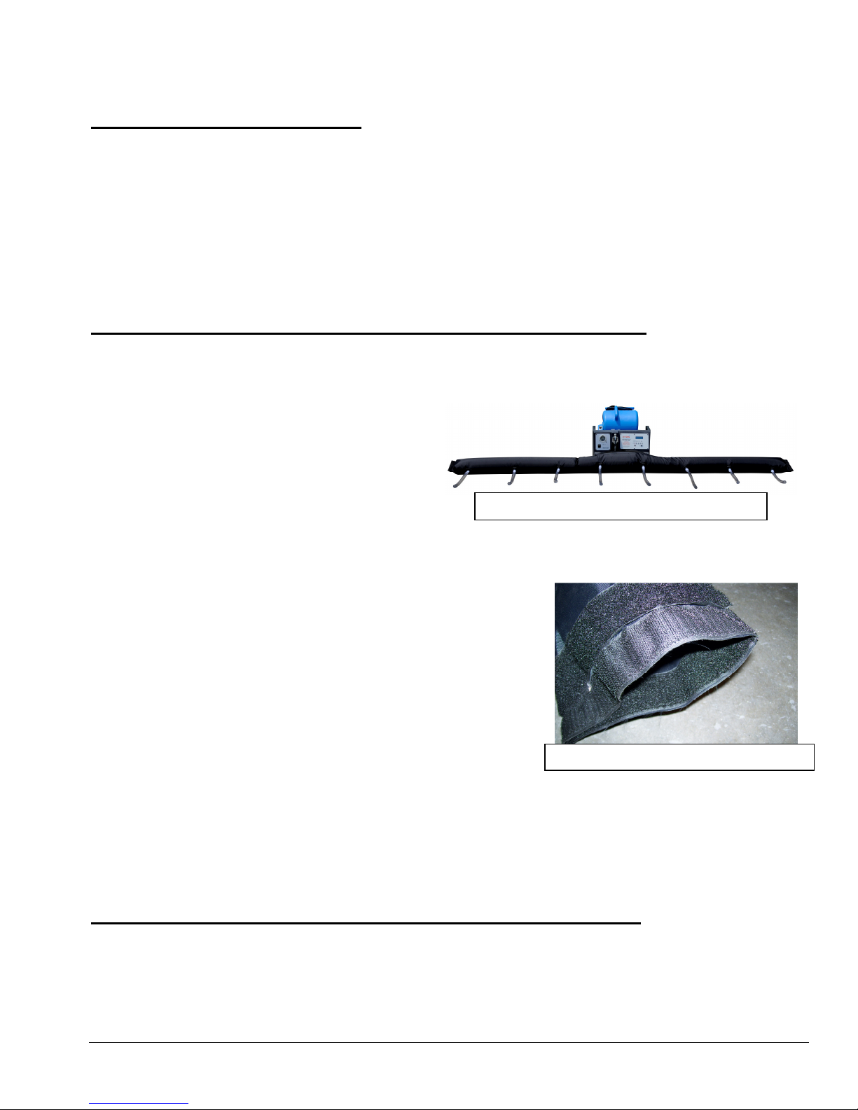
FLEXI Dry Secured to E
-
TES SD Snout
Wall Drying
End opened for increased airflow
Procedure
Step #1 – Access Wall Cavity
1. Remove the base board from the wall. Remove the base board carefully, including cutting any caulk bead
at the top to prevent damage to the drywall. If not damaged, the base board can be re-installed after the
drying process is completed.
2. Locate the wall studs in the area to be dried.
3. Drill 1” diameter access holes through the wall. Locate the holes between the studs, just above the wall
base plate. Whenever possible place holes where they will be covered by the base board after drying is
completed.
4. Insert one Flexi Dry outlet barb or hose into each hole. Turn tube to point air flow in the desired
direction. Multiple Flexi Fry units can be connected together for larger areas.
Step #2 - Energy applied directly to the water (Temperature)
1. Insert the snout of the E-TES SD unit into the large opening of the Flexi Dry. Secure the Flexi Dry to the
E-TES SD snout with the Velcro strap and the carpet clamp. Seal the ends of the Flexi Dry to prevent air
leaking. When using multiple Flexi Dry units connected together, seal the Velcro strips on the other large
openings to prevent air from leaking out.
2. Insert a centrifugal air mover into the E-TES
SD box. Plug the air mover cord into a wall
outlet. Connect the two GFCI power cords to
the E-TES SD 120volt unit and plug the cords
into two different 120v circuit outlets.
3. Place remote sensors for air temperature,
surface temperature and moisture level as needed in desired locations. Connect the sensors to the E-TES
SD.
4. Turn on the E-TES SD unit and adjust the set points for each
of the remote sensors as required for your application.
5. Turn on the air mover.
6. In some cases the Flexi Dry may restrict the E-TES SD outlet
air flow enough to overheat and engage the E-TES snout
temperature sensor or the Safety Overtemp switches.
When using the FlexiDry, the Overtemp Light will often turn
ON & OFF as the snout overheats and cools off. The E-TES
SD will continue to operate and no adjustments are needed.
However if the air flow is restricted too much, the Heater
Safety Overtemp switches will engage, the unit will cycle ON & OFF a few times before it locks in the
OFF position and will not turn back ON until the E-TES power is turned OFF and back ON.
To prevent this, open one end of the Flexi Dry to increase the total airflow. Opening the end just a small
amount should increase the air flow enough to keep the E-TES SD operating. Opening the end too much
may reduce the flow through the outlet tubes and increase the drying time.
Step #3 - Airflow applied directly to the water (Evaporation)
1. We are getting air movement into the wall with the air mover / E-TES SD box and the Flexi Dry system.
We are heating the water to cause the evaporation, but the water vapor still needs to be removed from the
wall.
2.
If the wall is wet top to bottom, air outlet holes may need to be drilled at the top of the wall between the
studs to allow the water vapor to be removed from the wall cavity. If the wall is only wet at the bottom,
drill an outlet hole below the baseboard level to allow moist air to escape
Copyright Tes Drying Systems, 2014
54
.
Page 55
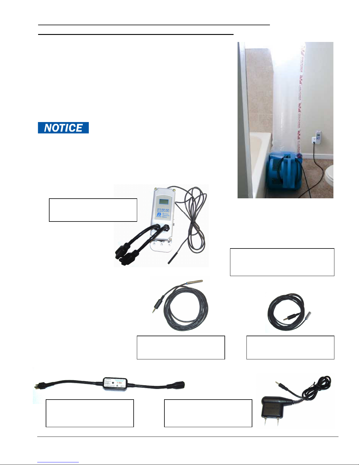
Step #4 - Reduction of vapor saturation levels (humidity) by
Air mover with ducting
Controller
Smart E
-
TES Remote
AT206
Air Temperature Sensor
Surface Temperature
Moisture Sensor
Exhaust Controller
dehumidification or evacuation (Dehumidification)
1. Now that we have evaporated the moisture into the air, we
need to remove it from the structure along with the excess
heat. This is accomplished with the exhaust controller, an air
mover, 14” lay flat duct and a duct ring. Set up the exhaust
system to evacuate to the outside of the structure.
2.
Set the Remote Activation temperature to turn on the exhaust
fan using the Smart E-TES Remote Exhaust Fan Control or
use a separate exhaust control unit set to keep the ambient
room temperature below 105ºF . (See Page 16 of this manual
or the instructions included with separate exhaust controller
unit).
Overheating the structure may cause damage
to structure or contents. Controlling the temperature is
important to prevent damage.
Monitor your progress at least daily – more often if practical.
Walls will dry quickly!
MB230
connected to Exhaust
AT202
Sensor AT200
Exhaust Fan Control
Copyright Tes Drying Systems, 2014
PGE5060
55
 Loading...