

Teryair SG-6K Operation & Maintenance Manual
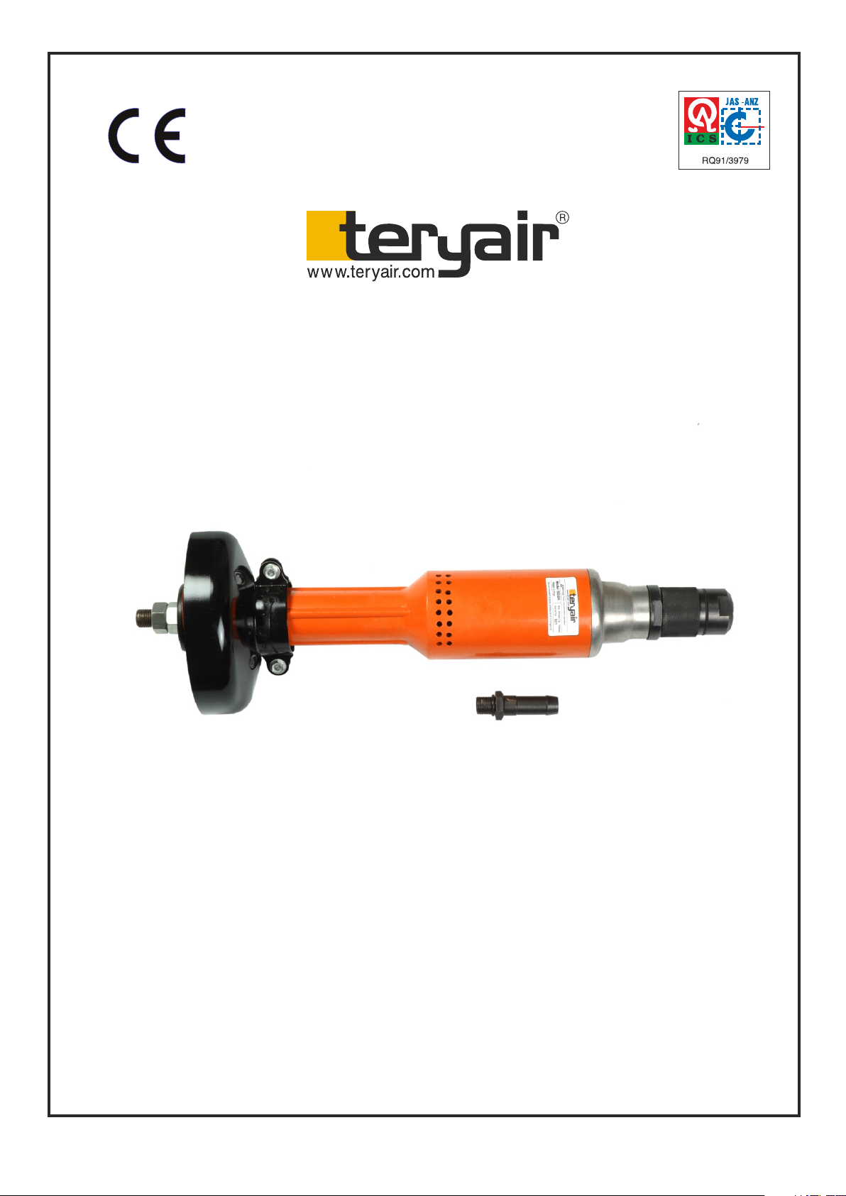
Pneumatic Straight Grinder
STRAIGHT GRINDER
SG-6K
SG6K
ISO 9001 : 2008
Operation & Maintenance Guide
Sheet 1 of 5
FF - MM - 75 REV - 0
Pneumatic Straight Grinder, SG-6K
Problem
Improper tightening of
mechanical parts or, improper
assembly of the tool.
Insufficient air flow (cfm)
Loss of
power
Use a line oiler, see char t on lubrication for oil selection.
Lowered compressor output
Excessive moisture in air
Repair compressor for proper output
Check hoses etc. for leaks
Disassemble tool, thoroughly clean and inspect all parts.
Check ball bearings for rough, bumpy action or exessive end
play. Check rotor blades for wear, damaged or swelling.
Replace defective parts, re-lubricate and re-assemble.
TROUBLE SHOOTING
SolutionProbable Causes
Low air pres sure at the tool For rated performance 90 psi air pressure is required at the
tool while tool operating
Foreign material in tool inlet. Rem ove foreign material
Tools run
erratically
If suggested remedies fail to correct the problem, dis-assemble and inspection m ust be performed to
determine the cause.
Operation and Maintenance Guide
AIR SUPPLY :
To enable the tool to function satisfactorily, it is essential that a constant 90 psi pressure of clean, dry air is supplied to the
hose connection (18). A short leader hose of 16mm I.D should be attached to the tool and the length of the pipe should
be less than 12 meters. The installation of air line separator, a filter to purify and dry the air supply (FRL unit)
recommended, and should be connected as close to the tool as operation will allow.
DAILY BEFORE OPERATION :
Disconnect and pour in 1 to 2 ounces of recommended oil into the air inlet and reconnect hose after blowing out any
accumulated dirt in the hose line before connection. Tighten both spindle nuts properly
SAFETY INSTRUCTIONS :
Always wear suitable protection, eye goggles, ear muffs, safety shoes etc to safe guard against possibility of flying
particles. Ensure that a wheel guard is fitted onto the tool and the wheel is secured properly.
Never operate the tool over the rated 90 psi pressure, Check that all bolts and other fasteners are tightened correctly. Do
not exert excessive pressure against the work surface. Never use larger wheels than recommended and check new
wheels for cracks before using them on the tool. Keep hoses in good condition. Check hoses for wear and ensure that
fittings are secure. Accidental disconnection while tool is in use can make the hose whip and can be safety hazard.
Remove wheel from the tool before attempting to dis- assemble this grinder . Check that the cause of the problem is not
external.Check that the inlet air pressure is O.K. i.e. 90 Psi. At the tool. Check for wet and dirty air moisture is not carried
into the tool, and corrode the internal parts. Dirt in the air tends to get into the motor parts and causes loss of
performance.
MAINTENANCE :-
A regular maintenance schedule will greatly add to the durability of the tool. Disconnect air supply to the tool. Unscrew
both spindle nuts (1) so that wheel collar (2) and one washer for wheel (3) will come out. Remove grinding wheel from
the tool. Take out another wheel collar (2) and washer (3)
Take out wheel guard (9) by loosening both nuts (5) remove clamp (8) and then take out hex head bolt (7) with plain
washers (6) With the help of a suitable wrench unscrew bearing clamp nut (10)
and remove it so that both ball bearings (14) will come out . Tap out gently to the spindle (12) so that
spindle (12) will come out from bearing (11) Remove coupling (15) Now from another end unscrew hose nipple (39)
along with ' O ' ring (38). Unscrew Air inlet bushing (37). Unscrew control body (33). Control body (33) will come out
along with rotary valve (34) and control sleeve (36). Remove
control sleeve (36) and tap out cylindrical pin (35) and slide out rotary valve (34) Also remove 'O' ring (32) Now with help
of spanner, unscrew rear housing (31) and remove it . Unscrew governor housing (26) and take it out. Tap out roll pin
(27) and remove seat (30), governor spring (29) then
housing cover (28) and all the three steel balls (25). Preserve all these items neatly.Pull out complete air motor. Tap out
ball bearing (24) so that lower end plate (18) will come out . Also remove rotor blades (19) and pull out rotor (20) from
another end of cylinder liner (21). Now tap out other end of rotor (20) and take out ball bearing (14) so that upper end
plate (16) and bearing spacer (17) will come out.
Sheet 2 of 5
FF - MM - 75 REV - 0
 Loading...