

Ter Welding Multi 250K, Multi 400K, Multi 500K DUO, Multi 500 MAR, Multi 400K DUO Instruction Manual
...
Multi 250 - 400K - 500F- 500K - 500 MAR e Accessories
This manual must be completed by the “CE Operating and service maual”
Edition of 29/05/2013
Instruction Manual
GB
English
Multi 250 - 400K - 500F - 500K - 500 MAR e Accessories
GB
English
Instruction Manual
Multi 250 - 400K - 500F - 500K - 500 MAR e Accessories
WARNING
IMPORTANT: BEFORE STARTING THE EQUIPMENT, READ THE CONTENTS OF THIS MANUAL, WHICH MUST BE STORED IN A PLACE FAMILIAR TO ALL
USERS FOR THE ENTIRE OPERATIVE LIFE-SPAN OF THE MACHINE.THIS EQUIPMENT MUST BE USED SOLELY FOR CUTTING OPERATIONS.
INTRODUCTION
To obtain the best performance from the machine and ensure the longest possible life of all its components you must careully follow the instructions for use and
maintenance detailed in this manual. In the interest of our customers we suggest any maintenance or repair of the equipment is made by qualied personnel.
All our products are subject to a constant development. We are therefore constrained to reserve the right to make any necessary or useful changes in design and
equipment.
ROUTINE MAINTENANCE
Prevent metal powder from accumulating inside the equipment. Disconnect the power supply before every operation ! Carry out the following periodic controls on
the power source:
• Clean the power source inside by means of low-pressure
compressed air and soft bristel brushes.
• Check the electric connections and all the connection cables.
For the use and maintenance of the pressure reducers, consult the specic manuals.
GB
English
Instruction Manual
Multi 250 - 400K - 500F - 500K - 500 MAR e Accessories
1. DECLARATION OF CONFORMITY
TER SRL - Via Leopardi, 13 - 36030 Caldogno (VI) Italy
declares that the machines descripted in this manual must be use solely for professional purposes in an industrial
environment and they are manufactured in compliance with the instructions contained in the harmonized standard:
2006/95/CE (LDV) – 2004/108/CE (EMC) – 2002/95 (RoHs)
and with the instructions contained in the harmonized standard,
if applicable:
EN 60974-1 EN 60974-2 EN 60974-3 EN 60974-5 EN 60974-7 EN 60974-10 EN 60974-12
Maurizio Terzo
Direttor Generale
Date 31/01/2012
IN CASE OF ANY TECHNICAL PROBLEM ASK FOR QUALIFIED SERVICE ASSISTANCE
The equipment don’t compiles with EN/ IEC 61000-3-12.
The installer or the user must be sure that it can be connected to the public low voltage power line,
if necessary, in consultation with the network distributor.
1
GB
English
Instruction Manual
Multi 250 - 400K - 500F - 500K - 500 MAR e Accessories
2. RAEE STANDARDS
The symbol on the product or on its packaging indicates that this product
may not be treated as household waste. Instead it shall be handed over to
the applicable collection point for the recycling of electrical and electronic
equipment. By ensuring this product is disposed of correctly, you will help
prevent potential negative consequences for the environment and human health,
which could otherwise be caused by inappropiate waste handling of this product.
For more detailed information about recycling of this product, please contact your
local city oce, your household waste disposal service or the shop where you
purchased the product.
3. SAFETY PRECAUTIONS
WELDING AND ARC CUTTING CAN BE HARMFUL TO YOURSELF AND OTHERS.
The user must therefore be educated against the hazards, summarized below, deriving from welding operations.
RISK of FIRE and BURNS
Sparks (sprays) may cause res and burn the skin; you should therefore
make sure there are no ammable materials in the area, and wear appropriate protective garments.
NOISE
This machine does not directly produce noise exceeding 80dB. The plasma cutting/welding procedure may produce noise levels beyond said limit;
users must therefore implement all precautions required by law.
PACE MAKER
The magnetic elds created by high currents may aect the operation of
pacemakers. Wearers of vital electronic equipment (pacemakers) should
consult their physician before beginning any arc welding, cutting, gouging
or spot welding operations.
EXPLOSIONS
Do not weld in the vicinity of containers under pressure, or in the presence
of explosive dust, gases or fumes. All cylinders and pressure regulators
used in welding operation should be handled with care.
ELECTRIC SHOCK – May be fatal
Install and earth the welding machine according to the applicable regulations. Do not touch live electrical parts or eletrodes with bare skin,
gloves or wet clothing.Isolate yourselves from both the earth and the
workpiece. Make sure your working position is safe.
FUME and GASES – May be hazardous to your health
Keep your head away from fumes. Work in the presence of adequate ventilation, and use ventilators around the arc to prevent gases from forming
in the work area.
ARC RAYS – May injure the eyes and burn the skin
Protect yuor eyes with welding masks tted with ltered lenses, and
protect your body with appropiate safety garments.
Protect others by installing adequate shields or curtains.
4. GENERAL DESCRIPTION
This machine is a constant direct current power source, designed for welding
electrically conductive materials (metals and alloys) using the electical arc
procedure.
2
GB
English
Instruction Manual
Multi 250 - 400K - 500F - 500K - 500 MAR e Accessories
5. PLC DEVICE POWER LINE CONTROLLER
On the MULTI single-phase generators equipped with PLC device. The domestic
(inside houses) power supply is normally limitated to 16A: the machine can be used
in such a conditions turning the PLC key, positioned on the rear panel, on 16A.
Note: use an industrial plug 25A at maximum power. The PLC key must be
positioned on 25A (industrial applications). Don’t use the 16A plug for industrial applications.
5.1 PLC function
The MULTI 250K machine is an industrial power source for light/medium applications; the duty cycle is very high and the inverter architecture allows hight current
rates. When the machine is plugged on a domestic (house) power line, a plug 16A
should be mounted; the input current must be less than 16A in order to avoid the
switching-o of the main switch protecting the power line.
The PLC feature controls the input current, automatically inhibiting the welding process when the power input rises the limit of the main line switch (16A).
The power of the machine isn’t reduced, only the welding time (duty cycle) is concerned when the demanded current is highter than the available one.
5.2 PLC display
When the PLC inhibits the welding process, the current supply is breaked
immediately, and the front panel shows the PLC timer count down.
When the timer arrives to 0, the welding job can restart.
Please refer to the plots in order to avoid unexpected welding interruptions when
the machine is used on domestic lines.
6. STANDBY
The machine stops its main functions when it is
not continuosly used, in order to reduce the
power consumption at 10W; the “STANDBY”
icon lights. The fan works only when the machine
needs to be cooled down; during ligth
applications, the fan normally doesn’t work.
The water cooling unit, if any, works only on MIG
process; at the end of the mig welding process, it
works for further 180 sec.
7. VRD VOLTAGE REDUCTION DEVICE
This feature reduces the output no load voltage <15V.
It increases the safety conditions of the operator: the no load voltage is not dangerous but any contact between human body and live parts may cause a shock
with lost of equilibrium control or similar.
The VRD feature is activated with “VRD” light on. The feature is always “on”: the
system grants ecient arc stricking even with a no load voltage <15V.
On manual MIG process it becomes automatically “o”.
3
GB
English
Instruction Manual
Multi 250 - 400K - 500F - 500K - 500 MAR e Accessories
Sound Function
If mode mig or mig pulse is selected, any increase or decrease of the stored job,
done by the digital buttons of the torch, determines a sequence of sounds that
indicate the number on the arc. If the adjustment, however, is made on the conventional parameters, such as voltage or the wire speed, the sound accompanying the
increase or decrease of the parameter. A dierent sequence is emitted when they
are reached the minimum and maximum limits of the adjustment.
Inch Wire Function
This function is used during loading of the wire. I press the button on the mig torch
until the display shows the word “INC”, release the button and press again within 3
seconds. Now the wire advances quickly. To stop the process release the button.
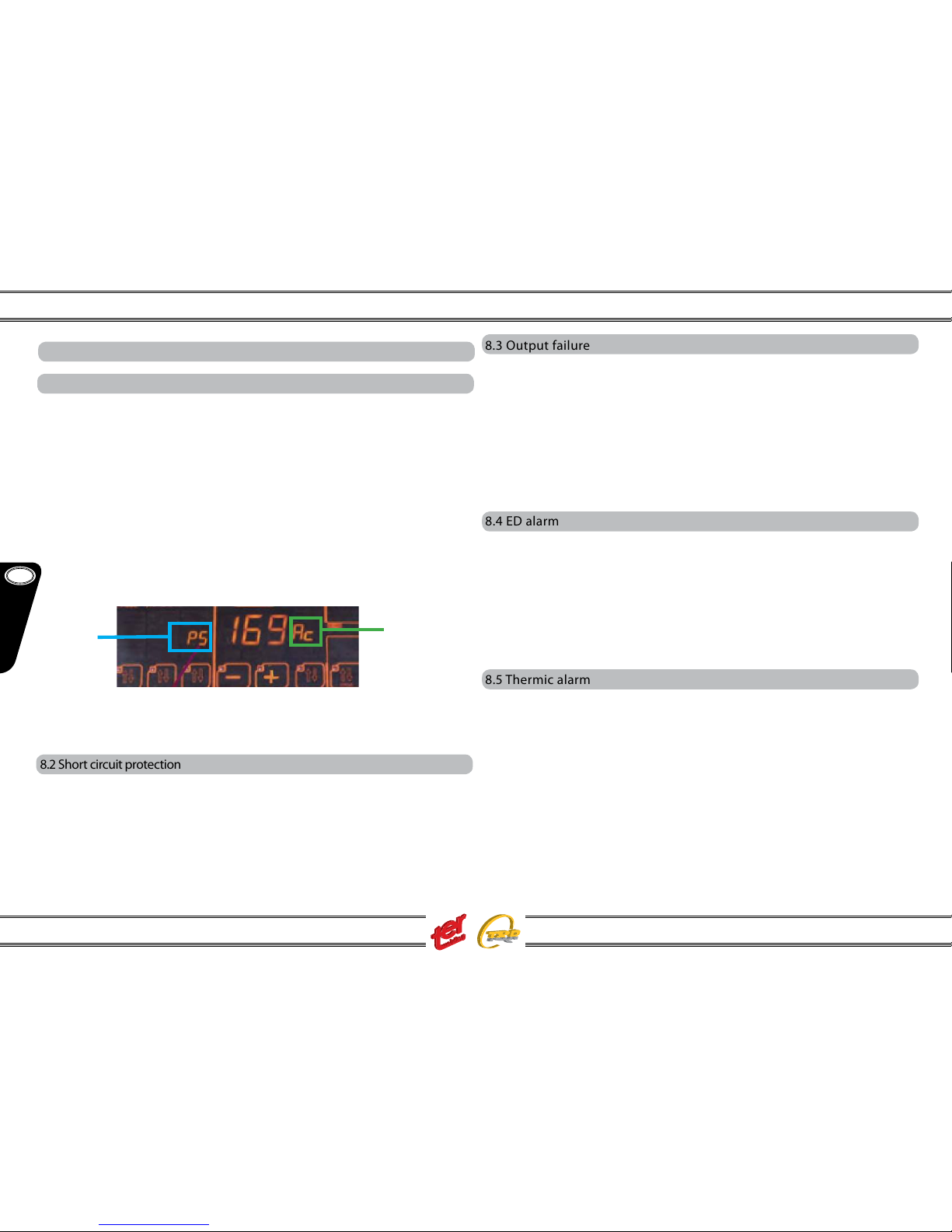
Wire Speed Calibration Function
With this process it is perfectly possible to calibrate the speed of the wire which, with the
use of dierent torches and welding wires with dierent diameter and consistency may
increase or decrease the drag. The procedure is as follows: Press the torch switch until the
ashlight shows “INC”, within 3 second press 3 times switch sw4, then, press again the
torch switch.
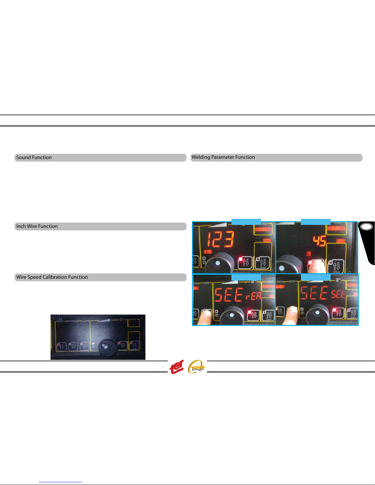
Welding Parameter Function
With this mode of operation the display, during the welding, indicating the actual values
of current and voltage. In default mode, however, only the set of welding parameters are
displayed. The function mode is activated by “MMA Manual”, set the encoder to the current
123 (PICTURE 1), press the button of the parameter 2 and with the encoder set “45” (PICTURE
2), now press the size button for 5 seconds, the message “SEE rEA” indicates that’ll display
the actual data (PICTURE 3). By pressing another 5 seconds will return to the original mode
and the display will read “SEE SEt” (PICTURE 4).
PICTURE 1
PICTURE 2
PICTURE 4PICTURE 3
4
sw4
GB
English
Instruction Manual
Multi 250 - 400K - 500F - 500K - 500 MAR e Accessories
8.3 Output failure
Fires, burns and shocks may be caused by uncorrect current outputs.
Reasons may be found on:
• involuntary failures on mig jobs which may release, without any control, the welding wire: it melt entering in contact with negative polarities generating possible re
and burn conditions
• damaged cables, with insulation losses, etc.
In case of any output failure, the machine enters in alarm condition showing:
ALL Out - Output Alarm
8.4 ED alarm
The MULTI serie generators are characterized by a high ED factor – 60% at 40°C
(40% in case of MULTI 250K) and power supply may, in certain cases, be insucient
causing damages on the exhisting supply network.
The MULTI serie controls regularly the input power value and in case of any
discrepancy display will shows:
ALL Ed xxx: The machine will be available again at the end of the count-down
shown on the display.
8.5 Thermic alarm
The MULTI serie generators are fan cooled. Forced ventilation is activated once the
inverter temperature exceed the 40°C and fan turns automatically o once internal
components are correctly cooled.
Fan cooling is anyway rarely activated: it may accur when duty cycle has been exceeded, in case of high environment temperatures, etc.
In case of overheating, output is disabled and display will shows:
ALL OL
The icon °C light on
Leave the machine on to allow a correct ventilation; when thermal conditions are
recovered, normal operations are again possible.
In case current exceeds the mentioned limits (current peaks), machine functions
stop and display shows the detected current peak. Reset the machine by switching the main ON/OFF knob.
The tri-phase version detects even the right presence of the three current phases and, should one of those fail for > 20 m/s, machine functions stop and display
will show the missing phase. Again, reset the machine by switching the main ON/
OFF knob.
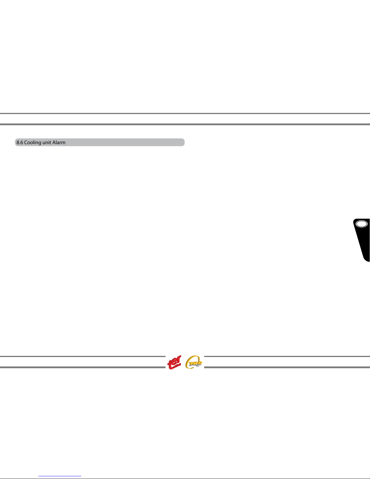
Power supply alarms that may appear on display:
PS XXX ac : power supply current peak
ALL Ph : current phase failure
8.2 Short circuit protection
A circuit test is released every time you switch “ON” the machine. The correct output
polarities are checked-out and in case of an eventual short circuit detection, machine enters in alarm standby showing on the display:
ALL Ph - alarm short circuit
Once short circuit conditions are removed, machine test will continue correctly.
Short circuit conditions may appear even during the welding job: in case they persist
continuosly for more than 5 sec, generator enter in “short circuit alarm”.
The “antisticking” icon lights too.
Power Supply
169V = current peak
8. ALARMS AND SETTINGS
8.1 Power supply alarms and setting
The single-phase welding generator MULTI 250K has an imput voltage of 230V
( min 170V – max 270V ). The tri-phase welding generators MULTI 400K and 500K
have an imput voltage of 400V ( min 340V – max 500V). Both single and tri-phase
versions can be supplied with motorgenerators and/or long cables (within the
min/max imput voltage limits).
5
GB
English
Instruction Manual
Multi 250 - 400K - 500F - 500K - 500 MAR e Accessories
8.6 Cooling unit Alarm
When the generator is equipped with the cooling unit, the correct cooling liquid circulation is constantly controlled. The cooling unit works only when Mig, Pulsed Mig
or Tig processes are activated.
The cooling unit pump is activated switching the torch trigger and turns o 4 minutes
after the welding job end.
In case of liquid circulation failures, output is disabled and display will show:
ALL h2o
Reset the machine switching the main knob ON/OFF.
Long unactivity periods may damage the cooling unit pump or generate momentary
re-start problems. First ensure the presence of liquid inside the tank and control the
right positioning of the in/out hoses – following instructions may help:
• unplug the water-out blu hose from the machine rear panel and plug a temporary
hose
• push & release the torch trigger once: cooling unit pump test should be activated
for 15 seconds
• cooling liquid should ow from the temporary hose: if not, repeat the pump test as
above
• once ensured the correct liquid owing, restore the original hose
• if necessary, control the correct liquid owing at the intermediary levels, i.e wire
feeder unit rear and front
6
GB
English
Instruction Manual
Multi 250 - 400K - 500F - 500K - 500 MAR e Accessories
9. MAIN FEATURES:
Power Source Type Multi 250K Multi 400K Multi 500K Multi 500F Multi 500 MAR
Code
Power supply ( -10% / +15% ) 230V 400V 400V 400V 400V
Phases 1ph 3ph 3ph 3ph 3ph
Fuses T25A T25A T32A T32A T32A
Rated Duty Cycle in 10 min ED 40% ED 60% ED 60% ED 60% ED 60%
Rated secondary current 250A 400A 500A 500A 400A
Permanent Sec. Current 100% 160A 310A 380A 380A 380A
Rated power 8,7KVA 18KVA 26K VA 26K VA 26 KVA
Permanent power 100% 5,5 KVA 12,5KVA 17,5K VA 17,5K VA 17,5K VA
Overload protection DIGITAL DIGITAL DIGITAL DIGITAL DIGITAL
TIG Regulation eld 10A-250A 10A-400A 10A-500A 10A-500A 10A-500A
STICK Regulation eld 20A-220A 20A- 400A 20A-500A 20A-50 0A 20A-500A
Range di regolazione MIG - MAG – MIG PULS 20A-250A 20A-400A 20A-500A 20A-50 0A 20A-500A
NO LOAD voltage (S) (K) 90V 90V 90V 90V 90V
Max secondary current 320A 500A 640A 640A 640A
Short circuit limit 480A 850A 1050A 1050A 1050A
Protection class IP21S IP21S IP21S IP21S IP23
Insulating class H H H H H
Stick synergi programs N° 19 19 19 19 puls exp opt
Tig synergi programs N ° 18 18 18 18 puls exp opt
Mig-Mag syne rgi programs N° 18 18 18 18 puls exp opt
Pulsed Mig synergi progra ms N° 5 5 5 5 puls exp opt
Pulsed Mig Double Pulsation ok ok ok ok puls exp opt
Up grade 8-16-32 puls Mig program opt opt opt opt no
Optional water cooling unit no ok ok ok no
Optional kit DUO (second wire feeder) no ok ok ok no
Double gas bottle trolley opt. no no ok ok no
Digital remote control Mig torch optional ok ok ok ok puls exp opt
Remote control receptacle ok ok ok ok puls exp opt
Digital Amperometer voltmeter ok ok ok ok ok
Width - Height Length mm 340x400x620 340x400x620 650x820x960* 340x600x620* 340x600x620*
Weight Kg 24 30 85 50 50
* Height of the Multi 500
Note: dimentions and weight are without wire feeder, without cooler unit
10. JOBS and SETTING
The MULTI generators serie can be divided in three categories:
- K Serie
- K Serie + DUO kit
- F Serie and MAR Serie
7
GB
English
Instruction Manual
Multi 250 - 400K - 500F - 500K - 500 MAR e Accessories
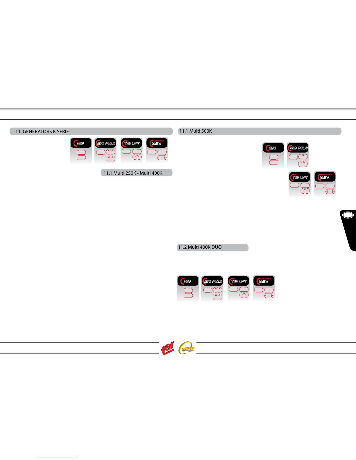
11. GENERATORS K SERIE
- Multi 250K
- Multi 400K
- Multi 500K
- Multi 400K DUO
- Multi 500K DUO
11.1 Multi 250K - Multi 400K
They can be equipped with trolley;
the 400K version even with cooling
unit. Mode and job settings
achievable directly from the front
panel.
With the rst left hand side key you can select the welding process between:
MMA (manual or synergic)
TIG (manual or synergic)
PULSED TIG (manual or synergic)
MIG-MAG (manual or synergic)
PULSED MIG (synergic and synergic/double pulsed)
Once welding mode is choosed, the machine will always recall the last used
program or the last used setting.
11.1 Multi 500K
It can be equipped with trolley and cooling unit.
Generators K Serie with Duo kit (secondary wire feeder unit)
11.2 Multi 400K DUO
It can be equipped with trolley and cooling unit.
The DUO conguration (double torch) provides
double job programs; on the main generator you
can select between:
MMA (manual or synergic)
TIG (manual or synergic)
PULSED TIG (manual or synergic)
MIG-MAG (manual or synergic)
PULSED MIG (synergic and synergic/double pulsed)
Pulsed
MIG
Sinergyc
MIG
MIG PULS
Sinergyc
MMA
VRD
MMA
CELLULOSIC
Sinergyc
TIG
TIG LIFT
DC
Sinergyc
MIG
MIG
Manual
Manual
Double
Pulsed
MIG
Pulsed
TIG
Manual
Pulsed
MIG
Sinergyc
MIG
MIG PULS
Sinergyc
MMA
VRD
MMA
CELLULOSIC
Sinergyc
TIG
TIG LIFT
DC
Sinergyc
MIG
MIG
Manual
Manual
Double
Pulsed
MIG
Pulsed
TIG
Manual
Pulsed
MIG
Sinergyc
MIG
MIG PULS
Sinergyc
MMA
VRD
MMA
CELLULOSIC
Sinergyc
TIG
TIG LIFT
DC
Sinergyc
MIG
MIG
Manual
Manual
Double
Pulsed
MIG
Pulsed
TIG
Manual
8
GB
English
Instruction Manual
Multi 250 - 400K - 500F - 500K - 500 MAR e Accessories
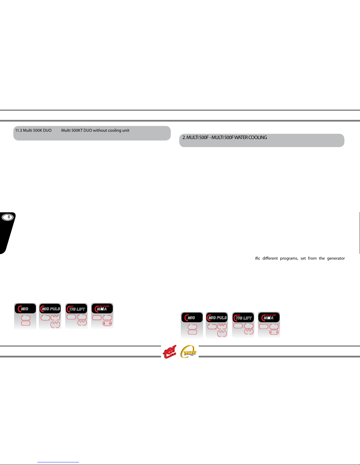
11.3 Multi 500K DUO Multi 500KT DUO without cooling unit
On the wire feeder unit you can choose between:
MIG-MAG (synergic)
PULSED MIG (synergic)
PULSED MIG (synergic/
double pulsed)
MIG-MAG (manual)
MMA
Job transfer from main generator
to wire feeder unit or viceversa is
released automatically switching
the corresponding torch trigger,
pushing the knob on the main
panel or any key on the wire
feeder panel.
When the main generator torch is working, the remote wire feeder unit will display
“INT CNT” meaning someone is using the main unit.
Once welding mode is choosed, the machine will always recall the last used program or the last used setting.
12. MULTI 500F - MULTI 500F WATER COOLING
It can be equipped with cooling unit and can work as standard MMA and TIG DC
power source.
On the generator main panel you
can select between:
MMA (manual or synergic)
TIG (manual or synergic)
PULSED TIG (manual or synergic)
while from remote wire feeder unit:
MIG-MAG (synergic)
PULSED MIG (synergic)
PULSED MIG (synergic/double pulsed)
MIG-MAG (manual)
MMA
Every welding job can work with specic dierent programs, set from the generator
main panel.
Job transfer from main generator to wire feeder unit or viceversa is released automatically switching the corresponding torch trigger, pushing the knob on the main panel or
any key on the wire feeder panel.
When the main generator torch is working, the remote wire feeder unit will display “INT
CNT” meaning someone is using the main unit.
Once welding mode is choosed, the machine will always recall the last used program
or the last used setting.
Pulsed
MIG
Sinergyc
MIG
MIG PULS
Sinergyc
MMA
VRD
MMA
CELLULOSIC
Sinergyc
TIG
TIG LIFT
DC
Sinergyc
MIG
MIG
Manual
Manual
Double
Pulsed
MIG
Pulsed
TIG
Manual
Pulsed
MIG
Sinergyc
MIG
MIG PULS
Sinergyc
MMA
VRD
MMA
CELLULOSIC
Sinergyc
TIG
TIG LIFT
DC
Sinergyc
MIG
MIG
Manual
Manual
Double
Pulsed
MIG
Pulsed
TIG
Manual
9
GB
English
Instruction Manual
Multi 250 - 400K - 500F - 500K - 500 MAR e Accessories
13. MULTI 500 MAR
The generator can be connected with the MIDI LPM wire feeder unit, able to provide
pulsed mig mode adding the relative kit
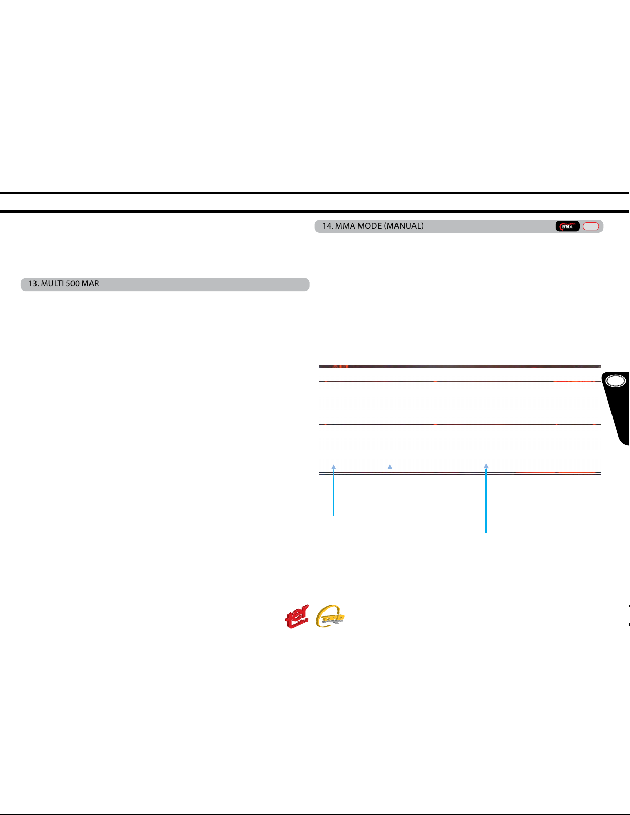
14. MMA MODE MANUAL
Connect the electrode holder and earth clamp to the right main generator polarities; the electrode holder can be connected even to the wire feeder unit – in that
case B and C setting steps are inhibited – on the wire feeder panel you can simply
adjust the welding current and arc dynamic (see wire feeder setting).
A - Select STICK
B - Select MANUAL
C – Adjust welding current….and weld
A - S elect S TICK
B - S elect M ANU AL
C – Ad just weld ing cur rent
A - Select STICK
B- Select MANUAL
C- Adjust welding current
MMA
CELLULOSIC
Manual
10
GB
English
Instruction Manual
Multi 250 - 400K - 500F - 500K - 500 MAR e Accessories
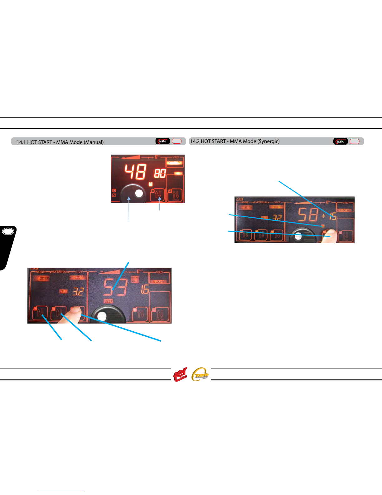
14.1 HOT START - MMA Mode (Manual)
The value can be adjusted according to the electrode type – Ex. stainless steel and
rutile electrodes demand a low value, near
to 0 – basic and the majority of the commun
electrodes a mi-value between 30/50 – cellulosic electrodes require a high value.
Push the 2nd level key until “HS” icon light on
– the led will blink for two seconds and during
this time adjust the required value. Two seconds after the last touch, “HS” setting mode
get o.
(see also wire feeder setting)
MMA mode (synergic)
MMA synergic welding is a really usefull way to avoid setting mistakes. Even skilled
welders can save job time entering the synergic mode:
2nd level key
Adjusting kno b
A -Select STICK B – Select electrode type C – Select electrode size
14.2 HOT START - MMA Mode (Synergic)
In synergic MMA mode the value is already set according to the choosed electrode.
The parameter can be changed anyway - adjustments are diplayed in % (pourcentage)
towards the original value:
push the 2nd level key until “HS” icon light on – the led will blink for two seconds and
during this time adjust the required value. Two seconds after the last touch, “HS” setting mode get o.
The adjustment is made using the main display knob, as usual.
The new parameter is automatically stored – it will be restored once recalling the same
program.
This setting is available only on the main generator panel.
NB: the welding current can be adjusted as well, remaining anyway inside the
programmed synergic values.
C – HS value increased of 15%
B – HS icon
A – 2nd level key
Welding Current
Adjusting knob
2nd level key
MMA
CELLULOSIC
Manual
MMA
CELLULOSIC
Manual
11

GB
English
Instruction Manual
Multi 250 - 400K - 500F - 500K - 500 MAR e Accessories
15.1 Current Setting - Tig Mode (Manual)
Turning the main display knob adjust the welding current.
NOTE: on manual tig mode the material tickness setting is not available.
15.2 Trigger Setting - Tig Mode (Manual)
Plug the tig torch to the negative polarity and the torch trigger plug to the respective socket. In case of remote control function, use the remote control socket.
Torch gas hose must be screwed to the machine gas nipple.
The welding generator can be equipped with cooling unit: in that case a water
cooled tig torch may be used plugging the water inlet/outlet hoses.
NOTE: generator provided with cooling unit can support even gas cooled tig
torches. Do not forget to close the water circuit by using a suitable by-pass
hose placed between the inlet and outlet nipples (front and rear).
Using an appropriate hose connect the gas bottle to the inlet gas nipple placed on
the rear panel (market with tig) – release the gas ow at 5/7 lt/min.
The MULTI generators provide tig torch arc strike by using the Lift-Arc method:
push the torch trigger
slow down the torch until the ceramic
nozzle touch the
workpiece; in this phase held the torch and
avoid any contact between tungsten and
workpiece
keeping the nozzle in contact, turn the
torch until the tungsten enters in contact
with the workpiece
maintaining the nozzle-work piece contact,
turn back the torch to the original position; the arc strikes and the welding can be
performed
A – Select TIG or TIG PULSE
B – Select MANUAL
(A) TIMER
it activates
the spot
function.
The spot arc
remains on
during the
set time
(B) 2T trigger
:
arc strikes when
torch trigger is
pressed, and
stops when
released
(C) 2T slope:
arc strikes when
torch trigger is
pressed, and
stops when
released with a
slope down
(D) 4T trigger:
arc strikes
pressing and
releasing torch
trigger. It stops
pressing and
releasing once
again
(E) 4T slope:
it’s like the 4T
trigger, adding a
current slope on
start and a slope
down current on
stop
15.TIG MODE MANUAL
TIG LIFT
DC
Manual
TIG LIFT
DC
Manual
TIG LIFT
DC
Manual
12
 Loading...