

TER SRL Multi Synergic 280, Multi Synergic 350, Multi Synergic 400F, Multi Synergic 500, Multi Synergic 500F Instruction Manual

Instruction Manual
Multi Synergic 280 - Multi Synergic 350 - Multi Synergic 400F - Multi Synergic 500- Multi Synergic 500F and Accessories
Multi Synergic 280 - Multi Synergic 350 - Multi Synergic 400F - Multi Synergic 500- Multi Synergic 500F and Accessories
This manual must be completed by the “CE Operating and service maual”
Edition of 26/03/2015
Instruction Manual
Multi Synergic 280 - Multi Synergic 350 - Multi Synergic 400F - Multi Synergic 500/500F and Accessories
GB
English

Instruction Manual
Multi Synergic 280 - Multi Synergic 350 - Multi Synergic 400F - Multi Synergic 500- Multi Synergic 500F and Accessories
Instruction Manual
Multi Synergic 280 - Multi Synergic 350 - Multi Synergic 400F - Multi Synergic 500- Multi Synergic 500F and Accessories
INDEX
DESCRIPTION CHAP. PAGE
1. DECLARATION OF CONFORMITY 05
2. RAEE standards 06
3. Safety precautions 06
4. General description 06
5. STAND BY 07
6. VRD - VOLTAGE REDUCTION DEVICE 07
7. ALARMS AND SETTINGS 07
8. POWER SUPPLY QUALITY IN THE VOLTAGE, IN THE MISSING PHASE, 07
IN THE FREQUENCY
9. OUTPUT WELDING CONDITIONS, SHORT CIRCUIT OR WELDING OVER LIMITS 07
10. AUXILIARY ELECTRONIC WARNING AND FAILURE 08
11. WATER COOLING UNIT STATUS 08
12. COMMUNICATION WITH THE EXTERNAL WIRE FEEDER 08
13. SPECIAL FUNCTIONS 09
14. ACCESSORIES 10
16. MAIN FEATURES MULTI SYNERGIC 350 11
17. MAIN FEATURES MULTI SYNERGIC 500 12
18. MAIN FEATURES MULTI SYNERGIC 500F 13
19. FRONT PANEL FUNCTIONS AND ADJUSTMENTS 14
20. FRONT PANEL LAYOUT 15
21. MANUAL ELECTRODE SETTING. CONNECT THE WORK PIECE CABLE TO 16
THE NEGATIVE RECEPTACLE, AND THE ELECTRODE OLDER T THE POSITIVE
RECEPTACLERECEPTACLE
22. TIG SETTING. CONNECT THE GAS INPUT TO THE GAS REGULATOR AND 17
ADJUST THE GAS FLOW BETWEEN 6 TO 8 LITRES PER MINUTE. DJUST THE
GAS FLOW BETWEEN 6 TO 8 LITRES PER MINUTE
DESCRIPTION CHAP. PAGE
23. MANUAL PULS TIG SET 18
24. SYNERGIC TIG SETTING 19
25. MIG-MAG WELDING 20
26. MIG-MAG MANUAL 21
27. MIG-MAG SYNERGIC 22
28. PULS MIG SYNERGIC 23
29. PULS MIG SYNERGIC PROGRAMS 24
30. MIG SYNERGIC PROGRAMS 24
31. DIGITAL TORCH 26
32. MULTI SYNERGIC 280 SPART PARTS 27
35. MULTI SYNERGIC 280 WELDING DIAGRAM 30
36. MULTI SYNERGIC 350 SPART PARTS 31
39. MULTI SYNERGIC 350 WELDING DIAGRAM 34
40. MULTI SYNERGIC 500 SPART PARTS 35
43. MULTI SYNERGIC 500 WELDING DIAGRAM 38
44. MULTI SYNERGIC 500F SPART PARTS 39
47. MULTI SYNERGIC 500F WELDING DIAGRAM 42
48. MULTI fil MIG Remote Wire Feeder 43
49. MULTI FIL MIG WIRE FEEDER SPARE PARTS 51
50. MULTI FIL MIG WIRE FEEDER DIAGRAM 52
51. MULTI FIL MIG WIRE FEEDER SPARE PARTS - DIAGRAM 53
52. PACKED 54
53. HOW TO FIX THE TROLLEY IN THE POWER SOURCE 55
54. HOW TO FIX THE COOLER UNIT AND THE TROLLEY IN THE POWER SOURCE 56
Instruction Manual
Multi Synergic 280 - Multi Synergic 350 - Multi Synergic 400F - Multi Synergic 500- Multi Synergic 500F and Accessories
1
WARNING
IMPORTANT: BEFORE STARTING THE EQUIPMENT, READ THE CONTENTS OF THIS MANUAL, WHICH MUST BE STORED IN A PLACE FAMILIAR TO ALL
USERS FOR THE ENTIRE OPERATIVE LIFE-SPAN OF THE MACHINE.THIS EQUIPMENT MUST BE USED SOLELY FOR CUTTING OPERATIONS.
INTRODUCTION
To obtain the best performance from the machine and ensure the longest possible life of all its components you must careully follow the instructions for use and
maintenance detailed in this manual. In the interest of our customers we suggest any maintenance or repair of the equipment is made by qualied personnel.
All our products are subject to a constant development. We are therefore constrained to reserve the right to make any necessary or useful changes in design and
equipment.
ROUTINE MAINTENANCE
Prevent metal powder from accumulating inside the equipment. Disconnect the power supply before every operation ! Carry out the following periodic controls on
the power source:
• Clean the power source inside by means of low-pressure
compressed air and soft bristel brushes.
• Check the electric connections and all the connection cables.
For the use and maintenance of the pressure reducers, consult the specic manuals.
Instruction Manual
Multi Synergic 280 - Multi Synergic 350 - Multi Synergic 400F - Multi Synergic 500- Multi Synergic 500F and Accessories
5
1. DECLARATION OF CONFORMITY
TER SRL - Via Leopardi, 13 - 36030 Caldogno (VI) Italy
declares that the machines descripted in this manual must be use solely for professional purposes in
an industrial environment and they are manufactured in compliance with the instructions contained in
the harmonized standard:
2006/95/CE (LDV) – 2004/108/CE (EMC) – 2002/95 (RoHs)
and with the instructions contained in the harmonized standard, if applicable:
EN 60974-1 EN 60974-2 EN 60974-3 EN 60974-5 EN 60974-7 EN 60974-10 EN 60974-12
Maurizio Terzo Direttor Generale
Date 30/01/2012
IN CASE OF ANY TECHNICAL PROBLEM ASK FOR QUALIFIED SERVICE ASSISTANCE
The equipment don’t compiles with EN/ IEC 61000-3-12.
The installer or the user must be sure that it can be connected to the public low voltage power line,
if necessary, in consultation with the network distributor.
Instruction Manual
Multi Synergic 280 - Multi Synergic 350 - Multi Synergic 400F - Multi Synergic 500- Multi Synergic 500F and Accessories
6
2. RAEE STANDARDS
The symbol on the product or on its packaging indicates that this product
may not be treated as household waste. Instead it shall be handed over to
the applicable collection point for the recycling of electrical and electronic
equipment. By ensuring this product is disposed of correctly, you will help
prevent potential negative consequences for the environment and human health,
which could otherwise be caused by inappropiate waste handling of this product.
For more detailed information about recycling of this product, please contact your
local city oce, your household waste disposal service or the shop where you
purchased the product.
3. SAFETY PRECAUTIONS
WELDING AND ARC CUTTING CAN BE HARMFUL TO YOURSELF AND OTHERS.
The user must therefore be educated against the hazards, summarized below, deriving from welding operations.
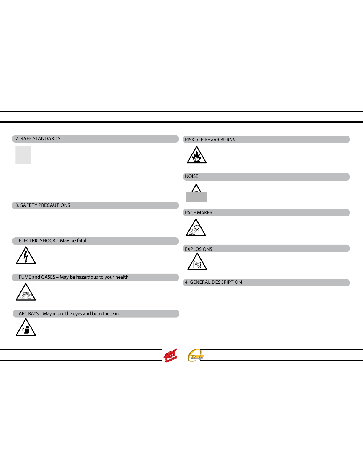
RISK of FIRE and BURNS
Sparks (sprays) may cause res and burn the skin; you should therefore
make sure there are no ammable materials in the area, and wear appropriate protective garments.
NOISE
This machine does not directly produce noise exceeding 80dB. The plasma cutting/welding procedure may produce noise levels beyond said limit;
users must therefore implement all precautions required by law.
PACE MAKER
The magnetic elds created by high currents may aect the operation of
pacemakers. Wearers of vital electronic equipment (pacemakers) should
consult their physician before beginning any arc welding, cutting, gouging
or spot welding operations.
EXPLOSIONS
Do not weld in the vicinity of containers under pressure, or in the presence
of explosive dust, gases or fumes. All cylinders and pressure regulators
used in welding operation should be handled with care.
ELECTRIC SHOCK – May be fatal
Install and earth the welding machine according to the applicable regulations. Do not touch live electrical parts or eletrodes with bare skin,
gloves or wet clothing.Isolate yourselves from both the earth and the
workpiece. Make sure your working position is safe.
FUME and GASES – May be hazardous to your health
Keep your head away from fumes. Work in the presence of adequate ventilation, and use ventilators around the arc to prevent gases from forming
in the work area.
ARC RAYS – May injure the eyes and burn the skin
Protect yuor eyes with welding masks tted with ltered lenses, and
protect your body with appropiate safety garments.
Protect others by installing adequate shields or curtains.
4. GENERAL DESCRIPTION
This machine is a constant direct current power source, designed for welding
electrically conductive materials (metals and alloys) using the electical arc
procedure.
Instruction Manual
Multi Synergic 280 - Multi Synergic 350 - Multi Synergic 400F - Multi Synergic 500- Multi Synergic 500F and Accessories
7
5. STAND BY
The machine stops its main functions when it is not continuosly used,
in order to reduce the power consumption at 10W; the “STANDBY” icon
lights. The fan works only when the machine needs to be cooled down;
during light applications, the fan normally doesn’t work.
The water cooling unit, if any, works only on MIG process; at the end of the mig welding process, it works for further 180 sec.
6. VRD - VOLTAGE REDUCTION DEVICE
This feature reduces the output no load voltage <25V.
It increases the safety conditions of the operator: the no load voltage is not dan-gerous but any contact between human body and
live parts may cause a shock with lost of equilibrium control or
similar.
The VRD feature is activated with “VRD” light on. The feature is always “on”:
the system grants ecient arc stricking even with a no load voltage <15V.
On manual MIG process it becomes automatically “o”.
To set the VRD on On or O, push the pushbutton for ten seconds up to the icon
VRD light on or the icon V>20 light on
7. ALARMS AND SETTINGS
The power sources Multi synergic are completed with a monitoring system of the
machine conditions in order to avoid failure in the machine and in the welding.
In particular the alarms involve in:
Power supply quality in the voltage, in the missing phase, in the frequency.
Output welding conditions, short circuit or welding over limits Inverter over heating
or over load or over current.
Auxiliary electronic warning and failure wire feeder status water cooling unit status
communication with the external wire feeder.
REFER TO THE TROUBLESHOOTING, PARAGRAPH FOR THE DE TAILS
8. POWER SUPPLY QUALITY IN THE VOLTAGE, IN THE MISSING
PHASE, IN THE FREQUENCY:
The tri-phase welding generators have an input voltage of 400V ( min 340V – max
480V). MULTI SYNERGIC versions can be supplied with motor generators and/or
long cables (within the min/max input voltage limits).
In case current exceeds the mentioned limits (current peaks), machine functions
stop and display shows the detected current peak.
Reset the machine by switching the main ON/OFF knob.
The tri-phase version detects even the right presence of the three current phases
and, should one of those fail for > 20 m/s, machine functions stop and display
will show the missing phase. Again, reset the machine by switching the main ON/
OFF knob.
In the case of shift of supply net frequency the machine is stopped an the appropriate alarm is shown in the display (this case can occurs when the supply is
coming from motor generator and the the frequency goes outside the limits of
50-60 Hz.
9. OUTPUT WELDING CONDITIONS, SHORT CIRCUIT OR
WELDING OVER LIMITS
A circuit test is released every time you switch “ON” the machine. The correct
output polarities are checked-out and in case of an eventual short circuit detection, machine enters in alarm standby showing on the display:
Once short circuit conditions are removed, machine test will continue correctly.
Short circuit conditions may appear even during the welding job: in case they
persist continuously for more than 5 sec, generator enter in “short circuit alarm”.
The “anti sticking” icon lights too.
Fires, burns and shocks may be caused by uncorrected current outputs.
Reasons may be found on:
• involuntary failures on mig jobs which may release, without any control, the
weld ing wire: it melt entering in contact with negative polarities generating possible fire and burn conditions
• damaged cables, with insulation losses, etc.
In case of any output failure, the machine enters in alarm condition showing: ALL
OUT
Instruction Manual
Multi Synergic 280 - Multi Synergic 350 - Multi Synergic 400F - Multi Synergic 500- Multi Synergic 500F and Accessories
8
The MULTI series generators are characterised by a its ED factor – 40% at 40°C and
power supply may, in certain cases, be sucient for this output but the used can
adjust higher power output causing damages on the existing supply network. (or can
use long interconnecting cable at maximum output current).
The MULTI SYNERGIC series controls regularly the output power Vs the input power
value and in case of any discrepancy the welding stops and the display will shows:
ALL Ed xxx: The machine will be available again at the end of the count-down
shown on the display.
INVERTER OVER HEATING OR OVER LOAD OR OVER CURRENT
The MULTI SYNERGIC series generators are fan cooled. Forced ventilation is activated
once the inverter temperature exceed the 40°C and fan turns automatically o once internal components are correctly cooled.
Fan cooling is anyway rarely activated: it may occurs when duty cycle has been exceeded, in case of high environment temperatures, etc.
In case of overheating, output is disabled and display will shows:
ALL OL
10. AUXILIARY ELECTRONIC WARNING AND FAILURE
The Internal electronic is governed by software and when errors come from the execution
of the cycles the display shows the alarms that can be ALL MEM, ALL TAB, I2C OCC,
when those alarms occurs may be the machine still works, refer to the troubleshooting
for the solution.
WIRE FEEDER STATUS
The wire feeder is digitally controlled, and ever, the wire speed has the right value,
in the case that something doesn’t works properly two alarms indicates the kind of
failure :
ALL ENC and ALL BRA that means a wrong or missing speed or a wrong or
missing brake status of the motor at the end of the welding, refer to the troubleshooting for the solution.
11. WATER COOLING UNIT STATUS
When the generator is equipped with the cooling unit, the correct cooling liquid circulation is constantly controlled. The cooling unit works only when Mig,
Pulsed Mig or Tig processes are activated.
The cooling unit pump is activated switching the torch trigger and turns off after
some time that the welding job end.
In case of liquid circulation failures, output is disabled and display will show:
ALL h2o
Reset the machine switching the main knob ON/OFF.
Long inactivity periods may damage the cooling unit pump or generate momentary re-start problems. First ensure the presence of liquid inside the tank and
control the right positioning of the in/out hoses – following instructions may help:
• unplug the water-out blu hose from the machine rear panel and plug a temporary hose
• push & release the torch trigger once: cooling unit pump test should be activated for 15 seconds
• cooling liquid should flow from the temporary hose: if not, repeat the pump
test as above
• once ensured the correct liquid flowing, restore the original hose
• if necessary, control the correct liquid flowing at the intermediary levels, i.e
wire feeder unit rear and front
12. COMMUNICATION WITH THE EXTERNAL WIRE FEEDER
The external wire feeder can be connected to the connectors of the back panel of the
machine, the machine recognise the wire feeder and starts to communicate.
The control from the machine is passed to the wire feeder when the torch switch
of the wire feeder is pressed or when one of the pushbuttons of the wire feeder is
touched.
When an error in the communication between the machine and the wire feeder appear, the two display of the wire feeder show thee lines instead the values, this problem often occurs when the interconnecting cable connectors are loose or internal
wires of the interconnecting cable are open.
Instruction Manual
Multi Synergic 280 - Multi Synergic 350 - Multi Synergic 400F - Multi Synergic 500- Multi Synergic 500F and Accessories
9
13. SPECIAL FUNCTIONS
RESET TO DEFAULT SETTING FUNCTION (default working parameters)
Press for 10 seconds the switch SW1 until the display show the menu load default
working parameters. Conrm YES by the switch under display yes.
LOCK JOBS FUNCTION
This function is activated only if insert the digital torch.
LOCK JOBS : press SW2 for 5 seconds.
UN LOCK JOBS : press SW2 for 10 seconds.
With LOCK JOBS is it only possible change the JOBS parameters.
All other setting are locked. If it press a switch or it moved a knob the display shows
“LOCK JOB” function activated.
SEE SET / SEE REAL FUNCTION
Set MANUAL MMA mode, set current 123A (in to display 1), set arcforce 45 (in to
dipslay 2).
Press SW3 for 3 seconds If is active the function see set, and you want activate the
function see real.
Press SW3 for 3 seconds If is active the function see real, and you want activate the
function see set.
In SEE SET mode during the welding the display show setting parameters.
In SEE REAL mode during the welding the display show real working parameters :
output current and output voltage.
SEE POWER MODULE TEMPERATUR FUNCTION
Set MANUAL MMA mode, set current 123A (in to display 1), set arcforce 50 (in to
dipslay 2).
Press SW3 for 3 seconds, unless the display show the temperatur read from the NTC
in the power module.
DISPLAY SOFTWARE VERSION FUNCTION OF ROUCH PANEL
Set MANUAL MMA mode, set current 123A (in to display 1), set arcforce 55 (in
to dipslay 2).
Press SW3 for 3 seconds, unless the display show the touch pannel software
version, and other parameter.
INC FUNCTION.
press torch switch for 3 seconds untill display show, INC and the motor stops.
Release and re-press the torch switch, the wire comes out without gas at speeds
up to 10 m / min.
SPEED WIRE CALIBRATION
press torch switch for 3 seconds, untill display show INC and the motor stops
release the torch switch and press SW4 button 3 times, untill display show SPD
SET, press torch switch again, the wire exits without gas first at three m/min and
then to 10 m/min, then stops. This operation serves to control board to calibrate
the motor speed and must be performed to load, with the wire inserted in the
sheath.
Instruction Manual
Multi Synergic 280 - Multi Synergic 350 - Multi Synergic 400F - Multi Synergic 500- Multi Synergic 500F and Accessories
10
14. ACCESSORIES
The Multi synergic series has the capability to recognise the accessory connected and
install it. The external wire feeder can be connected trough the interconnecting cable
and the machine recognise it and switch from internal control to wire feeder control
just using the torch switch or with a simple touch in the wire feeder or machine control.
The interconnecting cable is recognised in its impedance and automatically the parameter make a compensation in order to grant the same results also with dierent
length of the cables.
Digital torches, MIG or TIG can be installed also in a second time, the process recognise their presence and start to work in the SMART mode.
Water cooling unit can be installed with a simple operation to put the power source
over it and connect the cable. The process recognise it and start to drive the water
cooler in MIG or TIG, only during the welding and control the ow rate of the cooling
liquid. Remote control as manual or foot control can be connected in the front of the
machines and gives the adjustment in the main parameter without any extra setting
by the user. Digital remote control can be connected in the wire feeder, they work in
simple way,giving to the user a powerful extra control up to a smart interface to mechanical automatised applications.
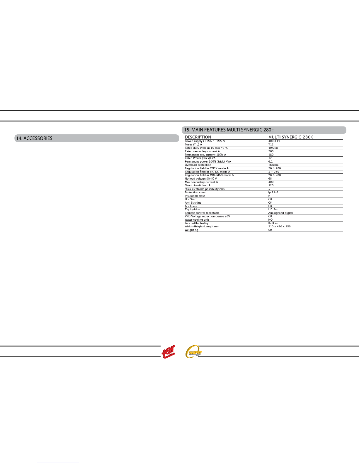
15. MAIN FEATURES MULTI SYNERGIC 280 :
The base machine includes the trolley and the bottle support, water cooling cannot
be used in the Multi Synergic 280, the accessories as external wire feeder and interconnecting cable can be used at any time as expansion. The other accessories as
digital torches and DRC can be connected at any time.
Three phase multifunction developed for light in-dustrial applications. The base machine is
equipped with robust digital
controlled wire feeder built
in, the trolley and ro-bust gas
bottle support.
Especially appreciate in the
synergic MIG-MAG applications with fast mig characteristic and for its easy to use au¬to-learning front panel.
Oer also the very often used pulse mig programs for aluminium wire 1,2mm, stainless steel 1,0 mm, mild steel 1,0 mm and silicon bronze 0,8 mm for these applications that needs something more, (the base program use the plus concept technology with double pulse capability).
Instruction Manual
Multi Synergic 280 - Multi Synergic 350 - Multi Synergic 400F - Multi Synergic 500- Multi Synergic 500F and Accessories
11
Included the welding process of Stick electrode and TIG features with manual adjustment or syn-ergic direct thickness adjustment.
This version of Multi Synergic 280 has the second wire feeder connected with ve
meters intercon-necting cable.
The external wire feeder can use a dierent pro-cess with also dierent wire and gas
from the built in wire feeder and allow an easy change of the work in use.
The selection between the two process, the inter-nal or the external is done only bypressing the torch switch of the process selected.
Dierent length of interconnecting cable can be selected from the accessory list.
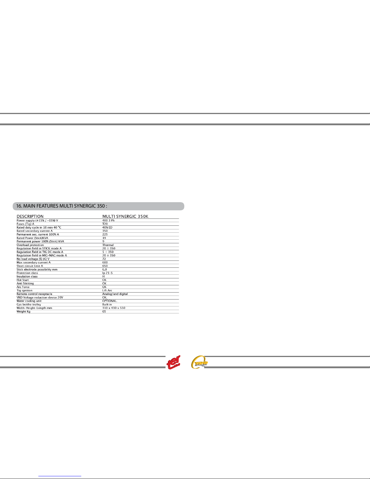
16. MAIN FEATURES MULTI SYNERGIC 350 :
The base machine includes the trolley and the bottle support, water cooling cannot
be used in the Multi Synergic 350 base but must be chosen the Multi Synergic 350W
that have built in the water cooling unit , the accessories as external wire feeder and
interconnecting cable can be used at any time as expansion. The other accessories
as digital torches and DRC can be connected at any time.
Complete version of the Multi synergic 350 for universal applications with the the
water cooling unit built in the bottom side of the trolley and the second wire feeder
connected with ve meters interconnecting cable.
The external wire feeder can use a dierent process with also dierent wire and gas
from the built in wire feeder and allow an easy change of the work in use.
The external wire feeder can use a water or air cooled torch.
The selection between the two process, the internal or the external is done only by
pressing the torch switch of the process selected.
Dierent length of interconnecting cable can be select-ed from the accessory list.
This version of Multi Synergic 350W has the water cooling unit built in the bottom
side of the trolley.
The water cooling system can be used in MIG-MAG and pulse mig process and
also in the TIG applications . Special controls drive the water cooling unit only during
the welding and monitor the eciency of the cooling liq-uid ow.
High power 350 three phase Multifunction with the latest innovation of the Multi
Synergic family.
With its 350A, 40% duty cycle is ideal for Industrial metal fabrications. The base
machine is equipped with robust digital controlled wire feeder built in, the trolley and
robust gas bottle support.
Especially appreciate in the synergic MIG-MAG applications with fast mig characteristic and for its easy to use au¬to-learning front panel.
Oer also the very often used pulse mig programs for alu-minium wire 1,2mm, stainless steel 1,0 mm, mild steel 1,0 mm and silicon bronze 0,8 mm for these applications that needs something more, (the base program use the plus concept technology with double pulse capability.
Included the welding process of Stick electrode and TIG features with manual adjustment or synergic direct thick-ness adjustment.
Instruction Manual
Multi Synergic 280 - Multi Synergic 350 - Multi Synergic 400F - Multi Synergic 500- Multi Synergic 500F and Accessories
12
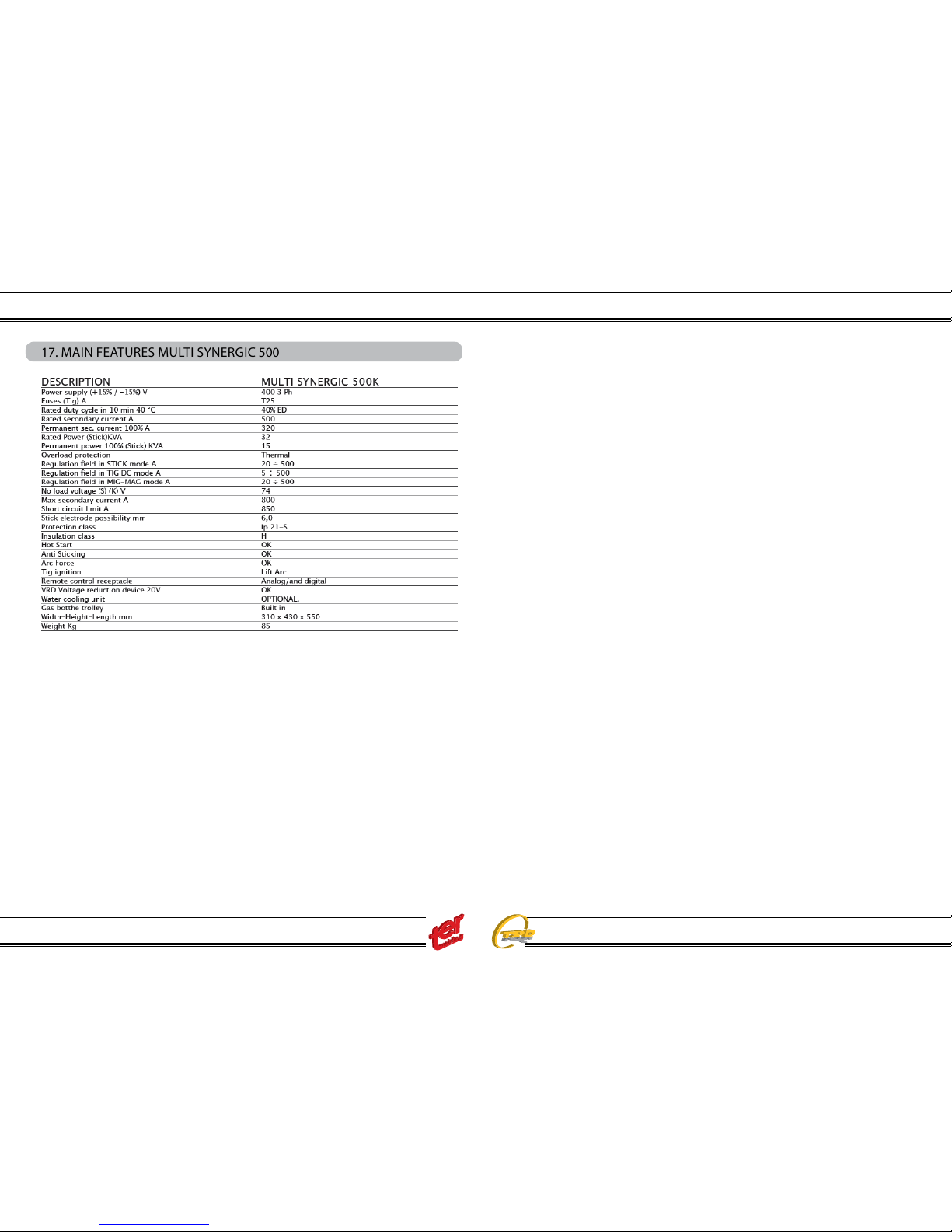
17. MAIN FEATURES MULTI SYNERGIC 500
The base machine includes the trolley and the bottle support, water cooling cannot be used in the Multi Synergic 500 base but must be chosen the Multi Synergic
500W that have built in the water cooling unit , the accessories as external wire
feeder and interconnecting cable can be used at any time as expansion. The other
accessories as digital torches and DRC can be connected at any time.
Complete version of the Multi synergic 500 for univer-sal and heavy applications with
the the water cooling unit built in the bottom side of the trolley and the sec-ond wire
feeder connected with ve meters intercon-necting cable.
The external wire feeder can use a dierent process with also dierent wire and gas
from the built in wire feeder and allow an easy change of the work in use.
The external wire feeder can use a water or air cooled torch.
The selection between the two process, the internal or the external is done only by
pressing the torch switch of the process selected.
Dierent length of interconnecting cable can be se-lected from the accessory list.
This version of Multi Synergic 500 has the water cool-ing unit built in the bottom side
of the trolley.
The water cooling system can be used in MIG-MAG and pulse mig process and also
in the TIG applications .
Special controls drive the water cooling unit only dur-ing the welding and monitor the
eciency of the cool-ing liquid ow.
Three phase multifunction developed for heavy indus-trial applications with 500A at
ED 40%. Complete manual and synergic multifunction with se-lection of MMA, TIG,
MIG MAG ideal for any kind of application.
The base machine is equipped with robust digital con-trolled wire feeder built in, the
trolley and robust gas bottle support.
Especially appreciate in the synergic MIG-MAG appli-cations with fast mig characteristic and for its easy to use au¬to-learning front panel.
Oer also the very often used pulse mig programs for aluminium wire 1,2mm, stainless steel 1,2 mm, mild steel 1,2 mm and silicon bronze for these applica-tions that
needs something more, (the base program use the plus concept technology with
double pulse capabi¬lity).
Included the welding process of Stick electrode and TIG features with manual adjustment or synergic direct thickness
Instruction Manual
Multi Synergic 280 - Multi Synergic 350 - Multi Synergic 400F - Multi Synergic 500- Multi Synergic 500F and Accessories
13
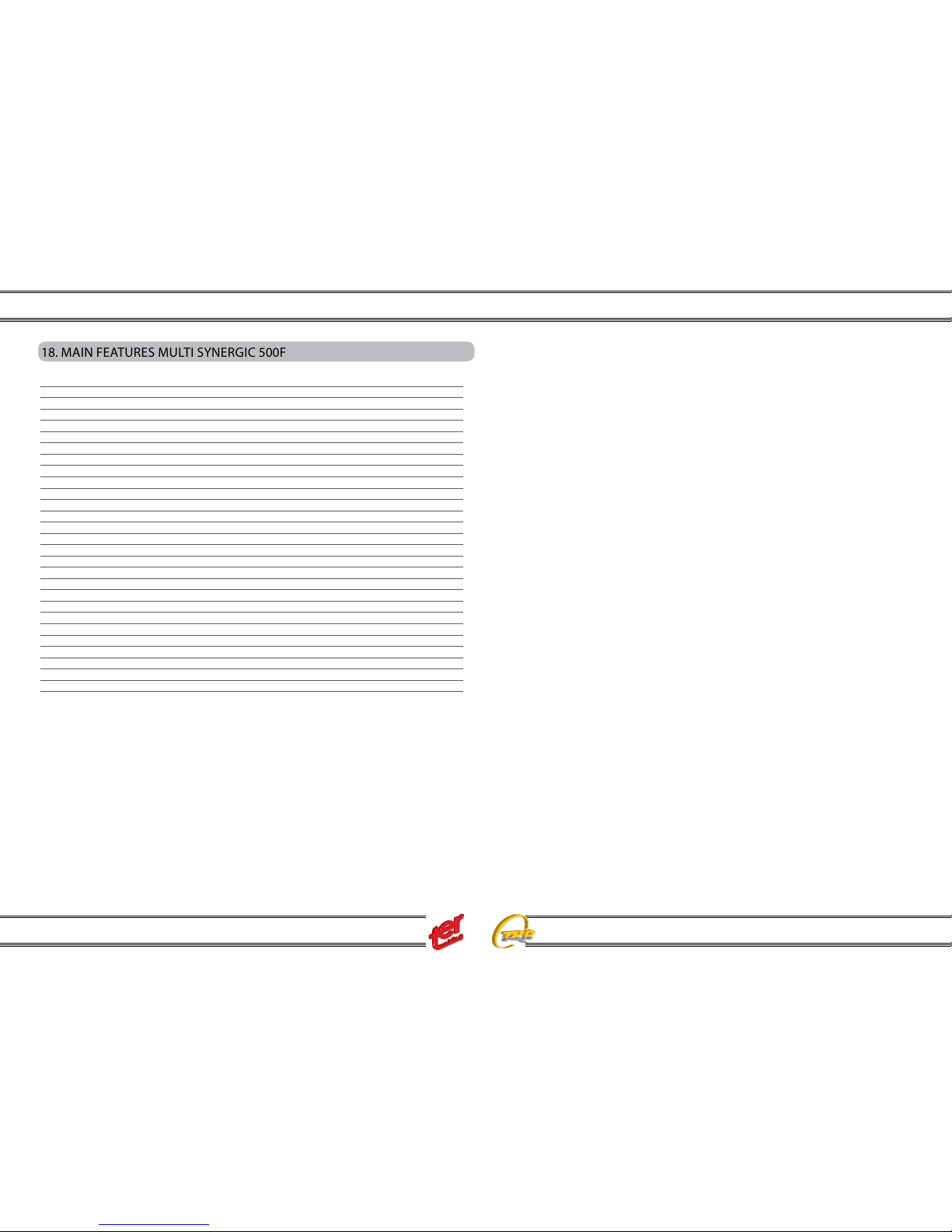
18. MAIN FEATURES MULTI SYNERGIC 500F
The base machine includes the trolley and the bottle support, water cooling cannot
be used in the Multi Synergic 500 base but must be chosen the Multi Synergic 500W
that have built in the water cooling unit. The accessories as digital torches and DRC
can be connected at any time.
The external wire feeder can use a water or air cooled torch.
Dierent length of interconnecting cable can be se-lected from the accessory list.
This version of Multi Synergic 500 has the water cool-ing unit built in the bottom side
of the trolley.
The water cooling system can be used in MIG-MAG and pulse mig process and also
in the TIG applications .
Special controls drive the water cooling unit only dur-ing the welding and monitor the
eciency of the cool-ing liquid ow.
Three phase multifunction developed for heavy indus-trial applications with 500A at
ED 40%. Complete manual and synergic multifunction with se-lection of MMA, TIG,
MIG MAG ideal for any kind of application.
The base machine is equipped with robust digital con-trolled wire feeder built in, the
trolley and robust gas bottle support.
Especially appreciate in the synergic MIG-MAG appli-cations with fast mig characteristic and for its easy to use au¬to-learning front panel.
Oer also the very often used pulse mig programs for aluminium wire, stainless steel,
mild steel and silicon bronze for these applica-tions that needs something more, (the
base program use the plus concept technology with double pulse capabi¬lity).
Included the welding process of Stick electrode and TIG features with manual adjustment or synergic direct thickness
DESCRIPTION MULTI SYNERGIC 500F MULTI SYNERGIC 500FW
Power supply (+15% / -15%) V 400 3 Ph 400 3 Ph
Fuses (Tig) A T25 T25
Rated duty cycle in 10 min 40 °C 40% ED 40% ED
Rated secondary current A 500 500
Permanent sec. current 100% A 320 320
Rated Power (Stick)KVA 32 32
Permanent power 100% (Stick) KVA 15 15
Overload protection Thermal Thermal
Regulation eld in STICK mode A 20 ÷ 500 20 ÷ 500
Regulation eld in TIG DC mode A 5 ÷ 500 5 ÷ 500
Regulation eld in MIG-MAG mode A 20 ÷ 500 20 ÷ 500
No load voltage (S) (K) V 74 74
Max secondary current A 800 800
Short circuit limit A 850 850
Stick electrode possibility mm 6,0 6,0
Protection class Ip 21-S Ip 21-S
Insulation class H H
Hot Start OK OK
Anti Sticking OK OK
Arc Force OK OK
Tig ignition Lift Arc Lift Arc
Remote control receptacle Analog/and digital Analog/and digital
VRD Voltage reduction device 20V OK. OK
Water cooling unit OPTIONAL. INCLUDED
Gas botthe trolley Built in Built in
Width-Height-Length mm 310 x 430 x 550 310 x 430 x 575
Weight Kg 85 85
MULTI SYNERGIC 500F MULTI SYNERGIC 500FW
Instruction Manual
Multi Synergic 280 - Multi Synergic 350 - Multi Synergic 400F - Multi Synergic 500- Multi Synergic 500F and Accessories
14
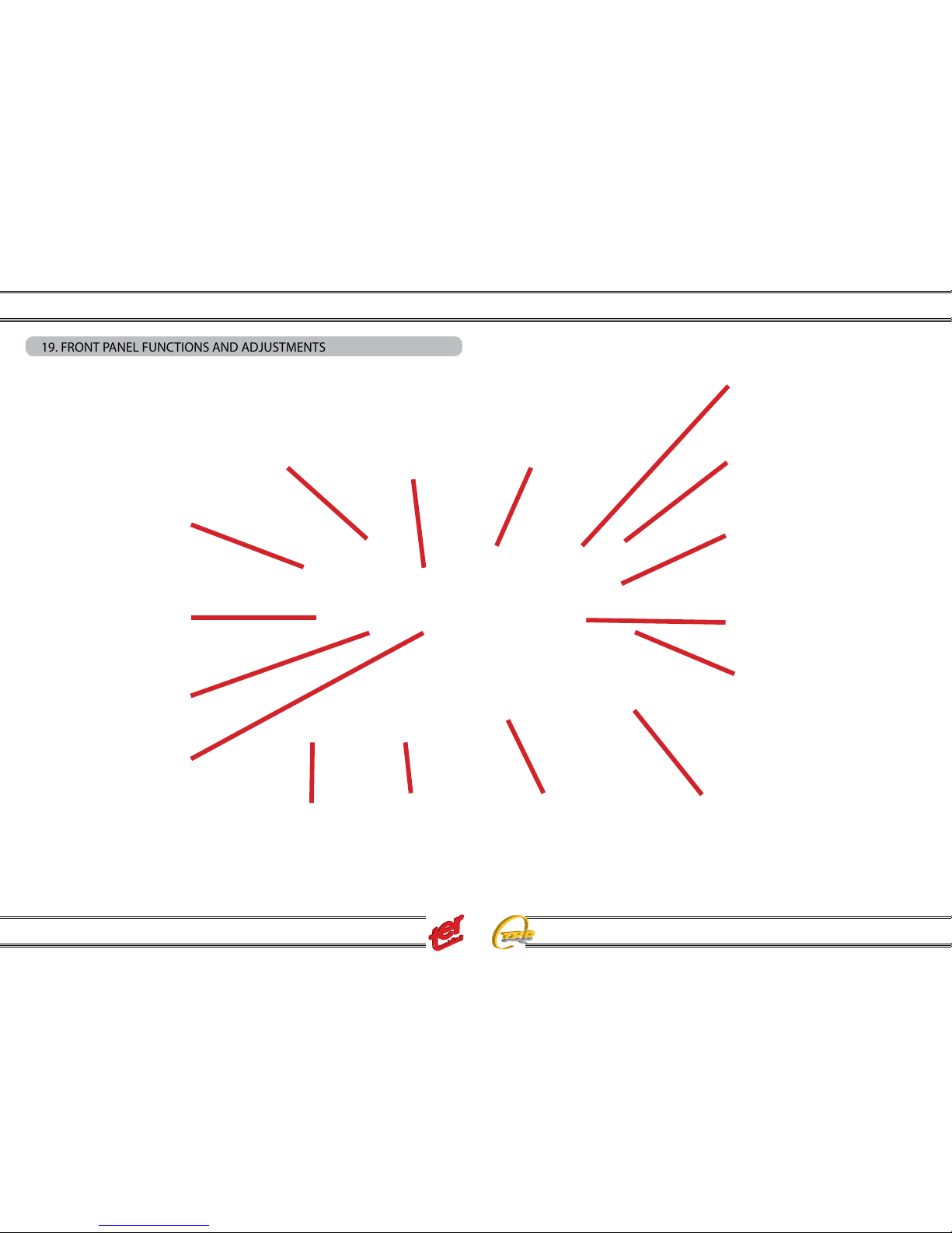
19. FRONT PANEL FUNCTIONS AND ADJUSTMENTS
Work mode in actual use.
The icons light on when
selected, between :
Mma; TIG, TIG PULSE; MIG
and MIG PULSE.
First pushbutton MODE,
allow to change the working
mode. The working MODE
are: Mma; TIG, TIG PULSE;
MIG and MIG PULSE.
Second pushbutton SYNERGIC
Trough this pushbutton, it is
possible to the modality manual
or synergic selecting the kind of
material under welding.
Third push button
Though this pushbutton is
possible to select that diameter,
in Mma the size of electrode, in
TIG the tungsten, and in Mig and
Pulse Mig the wire diameter.
This lamp, shows
if the digital torch
adjustment select
jobs or adjust the
welding parameter
in analog way.
Job position, any
welding processcan have its ownjobs levels. To
select jobs, the
digital torch must
be used.
Main knob
Modify the main in
welding: In MMA,
TIG, Synergic MIG
and Puls MIG adjust the current, in
Manual MIG adjust
the voltage.
Secondary knob.
Adjust the second level parameters:
MMA, Arc-force TIG, nothing Pulse
TIG, frequency Manual MIG,wire
speed Synergic Mig and Puls MIG,
the arclenght
Fifth pushbutton.
Trough this pushbutton is possible
to select the torch switch cycle:
2T; 2TS(with slopes);
4T; 4TS ( with slopes);
Timer.
In MMA is also possible select/deselect the function VRD helding
the pushbutton for 5
seconds.
Forth pushbutton, trough this pushbutton it is possible to adjust other
parameters that are in function with
the working modality chosen with
the rst pushbutton.
Torch switch cycle icons that can
be selected trough the fth pushbutton between:
Timer, simple two step, two step
with slopes, simple 4 step and 4
step with slopes.
Warning indications for VRD, over
heating, output in short circuit...
Area where are selected
the manual mode or, in
Synergy Mode, the material to be welded or
the type of electrode
used in MMA mode.
Area where are selected,
in Synergy Mode, the size
of the wire, or the size of
electrode in MMA mode or
the diameter of tungsten
electrode in TIG mode.
Main display, show, the
set and real voltage, in
MIGMAG manual mode,
or the set and real current
in the other setting.
In Alarm mode gets the
ALL indication.
Second display, shows the set wire
speed and real current in Manual
MIG-MAG mode, or the voltage, the
material thickness, the inductance,
the frequency of double pulsation..
In function of the selected icon
trough the forth push button.

Instruction Manual
Multi Synergic 280 - Multi Synergic 350 - Multi Synergic 400F - Multi Synergic 500- Multi Synergic 500F and Accessories
15
20. FRONT PANEL LAYOUT
FRONT PANEL
MIG TORCH
INTERNAL
WIRE FEEDER
ACCESS
TIG
TORCH
SWITCH
REMOTE
CONTROL
SOCKET
POSITIVE
OUTPUT
NEGATIVE
OUTPUT
TIG GAS OUT
TIG TORCH SWITCH
REMOTE CONTROL SOCKET
TIG GAS OUT
NEGATIVE OUTPUT
POSITIVE OUTPUT
ONLY MULTI SYNERGIC 500F AND MULTI SYNERGIC 500FW
Instruction Manual
Multi Synergic 280 - Multi Synergic 350 - Multi Synergic 400F - Multi Synergic 500- Multi Synergic 500F and Accessories
16
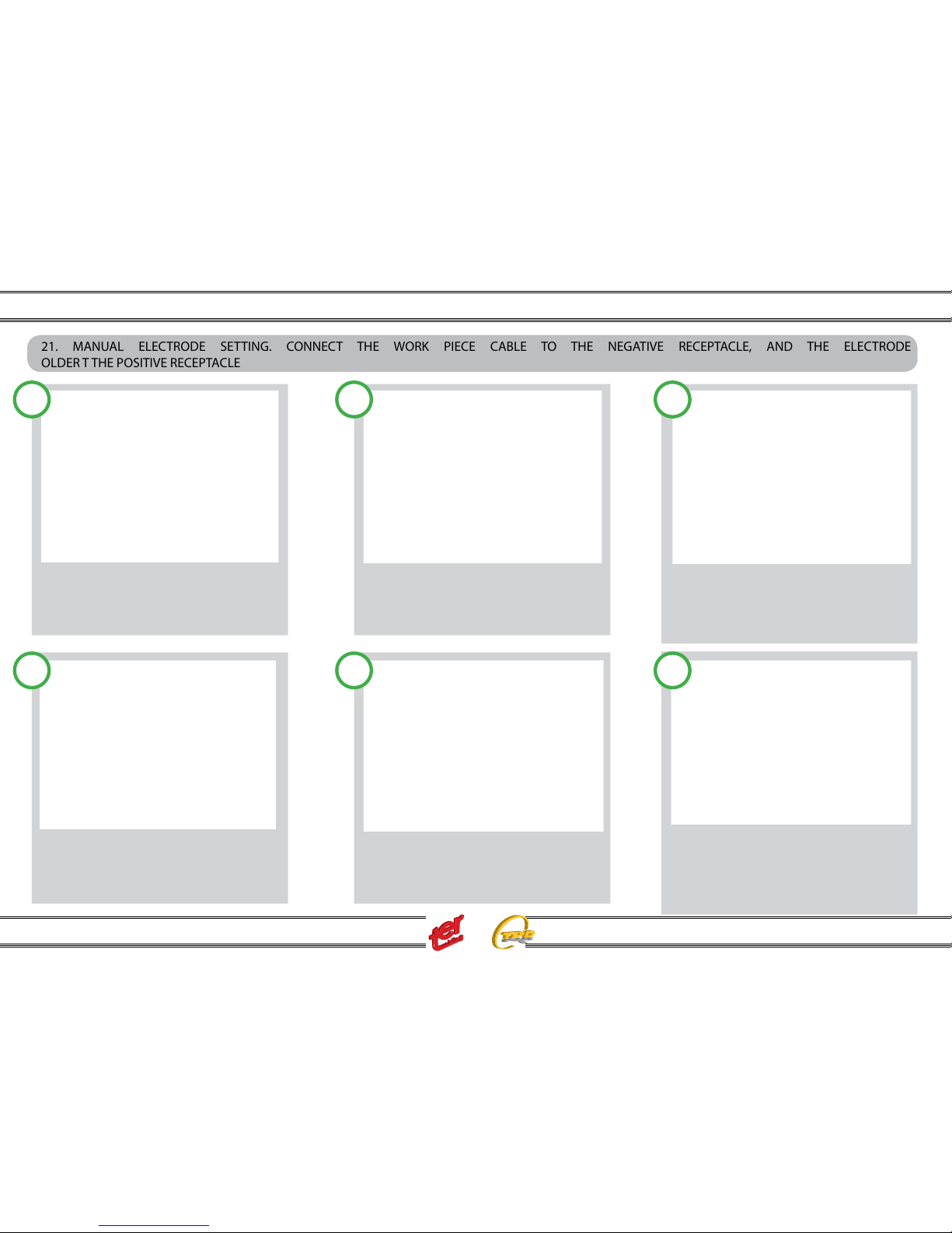
21. MANUAL ELECTRODE SETTING. CONNECT THE WORK PIECE CABLE TO THE NEGATIVE RECEPTACLE, AND THE ELECTRODE
OLDER T THE POSITIVE RECEPTACLE
SELECT MMA IN MANUAL:
With the rst push button, select STICK
With the second push button select MANUAL
With the main knob, adjust the welding current.
ADJUST THE WELDING DYNAMIC:
With the forth pushbutton select the dynamic
icon. The second display show the current set
value.
ADJUST THE WELDING DYNAMIC:
With the second knob, adjust the desired value
The dynamic can be adjusted from 0 to 100%
Dynamic increase the current for arc striking
Dynamic increase the current during drop transfer.
SELECT MMA IN SYNERGYC:
With the second push button, select the type
of the electrode.
SELECT MMA IN SYNERGYC:
With the third pushbutton select the size of the
electrode.
ADJUST THE WELDING CURRENT AND DYNAMIC:
With the FIRST knob, adjust the desired value,
the second display shows the material thickness.
Dynamic is automatic, but can be increased or
Decreased in % as the operator desire.
1 2 3
4 5 6

Instruction Manual
Multi Synergic 280 - Multi Synergic 350 - Multi Synergic 400F - Multi Synergic 500- Multi Synergic 500F and Accessories
17
22. TIG SETTING. CONNECT THE GAS INPUT TO THE GAS REGULATOR AND ADJUST THE GAS FLOW BETWEEN 6 TO 8 LITRES PER
MINUTE.
NOTE: generator provided with cooling unit can support even gas cooled tig torches. Do not forget to close the water circuit by using a suitable by-pass hose
placed between the inlet and outlet nipples (front and rear).
Full control of the cycle and easy access control. Pregas; initial current; up slope; down slope; final craterfiller
current; post gas pulser TIG version.
SELECT MANUAL TIG MODE:
With the rst push button, select TIG
SELECT THE TORCH
SWITCH CYCLE:
With the fth push
button select the torch
switch Cycle.
If the timer cycle is selected, than the time is
adjustable with the selection trough the forth
Push button.
ADJUST THE SECOND LEVEL PARAMETER
With the forth push button select the other
welding parameter and adjust, with the second
knob, to the desired value PRE GAS; POST
GAS, icons light on and the Second display
shows the value.
ADJUST THE TIG CYCLE PARAMETERS:
When a cycle 2 step with slopes or 4 step with
Slope, is selected, the forth knob has also the
Capability to select the start current, up slope,
down slope and stop current.
All the data are stored in the internal memory
push the torch trigger
slow down the torch until the ceramic
nozzle touch the
workpiece; in this phase held the torch and
avoid any contact between tungsten and
workpiece
keeping the nozzle in contact, turn the
torch until the tungsten enters in contact
with the workpiece
maintaining the nozzle-work piece contact,
turn back the torch to the original position; the arc strikes and the welding can be
performed
1 2 3
4 5
6
Instruction Manual
Multi Synergic 280 - Multi Synergic 350 - Multi Synergic 400F - Multi Synergic 500- Multi Synergic 500F and Accessories
18
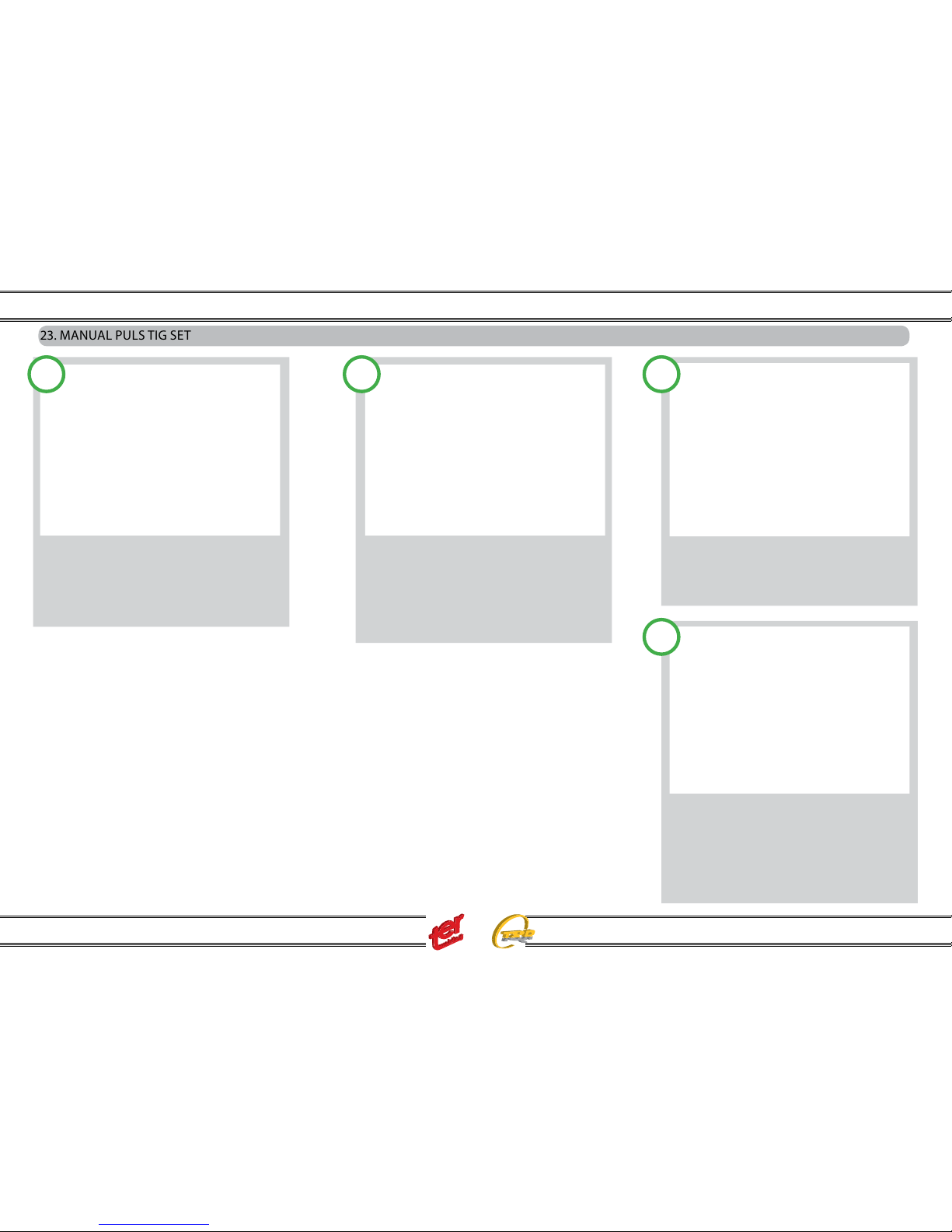
23. MANUAL PULS TIG SET
SELECT MANUAL PULSE TIG MODE:
With the rst push button, select TIG PULSE.
SELECT ALL THE OTHER PARAMETERS:
PULS TIG is a dierent session and have its
own Torch switch cycle, and second level parameters, they will be recovered when Manual
PULS TIG is selected, adjust all o them, as in
Manual Tig.
SELECT THE FREQUENCY:
With the forth push button is possible also to
select the frequency of pulsation and adjust it
The adjustment is from 0,2 Hz up to 2 KHz.
SELECT PULSE TIG PARAMETERS:
For the expert welders is also possible to adjust The parameters of pulsation as :
I LOW (background current during pulsation) and Balance ( ratio between ON and OFF in the pulse). The
peak pulse is self calculate by the processor
1 2 3
4
Instruction Manual
Multi Synergic 280 - Multi Synergic 350 - Multi Synergic 400F - Multi Synergic 500- Multi Synergic 500F and Accessories
19
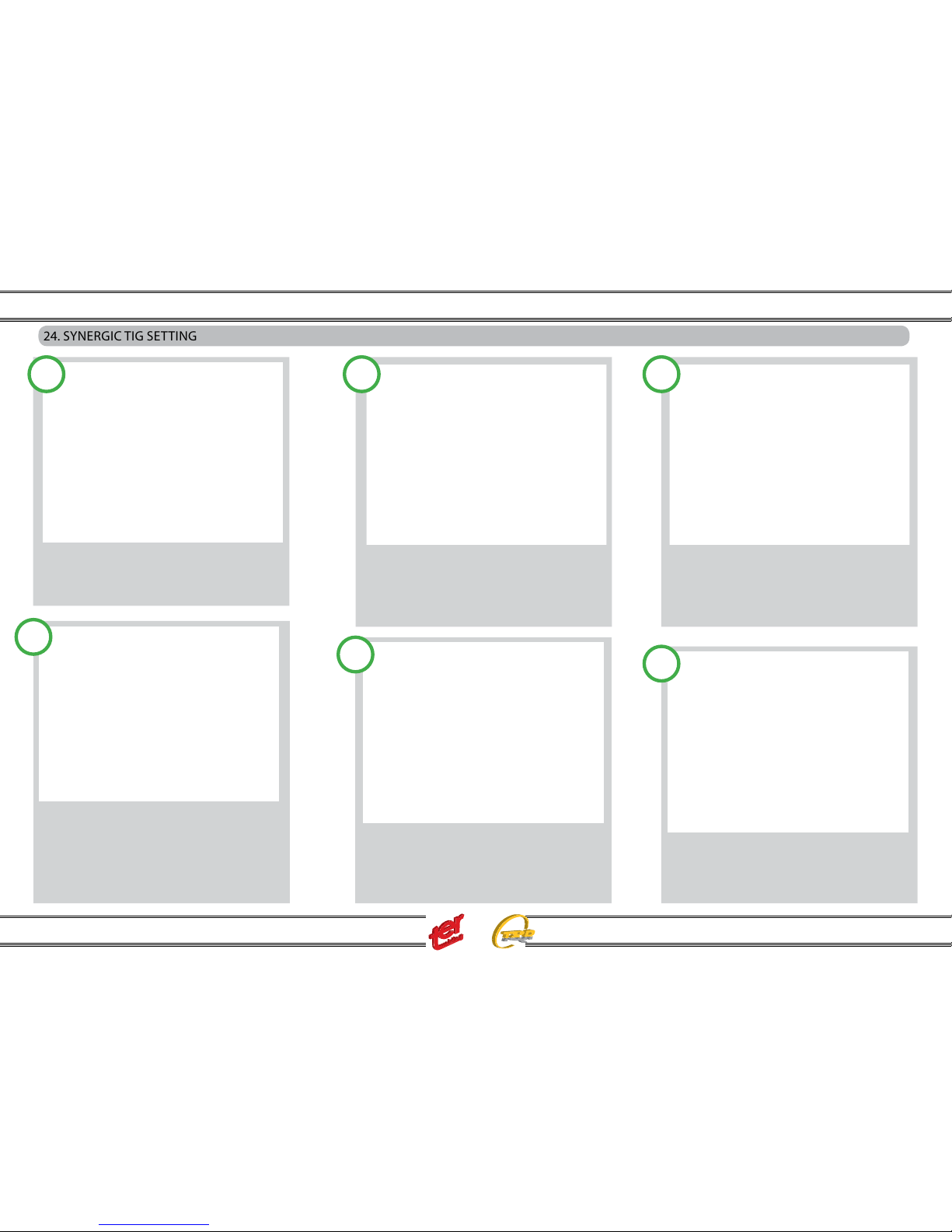
In this example, the down slope synergic value
is increased of 6%.
The value is stored in the internal memory.
24. SYNERGIC TIG SETTING
SELECT SYNERGY TIG OR PULSE MODE:
With the rst push button, select TIG or TIG
PULSE with the second push button select the
material in welding.
COMPLETE THE TIG SYNERGY SELECTION:
with the third push button select the diameter
of the tungsten electrode of the tig torch.
From this time all the adjustment are automatically done from the synergy selection.
Adjust the welding current , in the little display
The value of the suggested thickness of the
welding material is proposed. The selection
of the Torch switch cycles is the same of the
manual setting.
The second level parameters change as the set
current change giving ever the optimal value.
If the expert user need to increase or decrease
the synegic value of one of these values, push
the forth push button and select the value to
be changes.
1 2 3
4
Once selected the value that need to be
changed, Use the second knob to adjust.
The little display, shows the correction value in
% That can increase or decrease up to 100%
the current synergic value.
5
6
Instruction Manual
Multi Synergic 280 - Multi Synergic 350 - Multi Synergic 400F - Multi Synergic 500- Multi Synergic 500F and Accessories
20
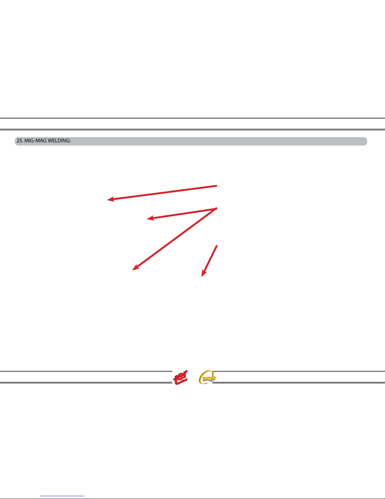
25. MIG-MAG WELDING:
MULTI SYNERGIC POWER SOURCE HAS THE POSSIBILITIES TO PERFORM MIG-MAG WELDING IN MANUAL OR IN SYNERGY, FOR ADVANCED
APPLICATION, THERE ARE ALSO THE POSSIBILITIES TO USE THE PROCESS PULS MIG FOR THE MOST COMMON MATERIALS.
The wire feeder unit can receive 200 or 300 mm size wire spools.
Make sure your wire spool is correctly and safely xed to the pinion
than adjust the friction screw.
a) match the driving rolls located into the driving motor with your wire
type and size.
b) insert the wire into the driving rolls and push it till the machine euro
adaptor. Lock the driving rolls properly.
c) connect the mig torch to the machine euro adaptor.
d) press the torch trigger: wire drives for 5 sec. and stops once the
display will light “INC”.
e) release the torch trigger and press it again: wire drives now into the
torch at 10 mt/min, until trigger remain pressed.
f) Fit the shielding gas hose in to the back panel of the machine
(gas nipple marked with MIG).
Adjust the ow rate between 16/22 lt/min. depending on the welding task.
g) connect the earth clamp plug to the negative polarity.
h) adjust the welding parameter in one of the following three mode : MANUAL, SYNERGY OR PULSE MIG.
 Loading...