

TER SRL MIG175GD User Manual

USER MANUAL
MIG175GD


USER MANUAL - 1 - YF-74L A2
CONTENTS
1. CONTENTS .................................................................................................................... 1
2. SAFETY WARNING ............................................................................................................................. 2
3. PRODUCT DESCRIPTION .................................................................................................................. 7
4. TECHNICAL PARAMETERS .............................................................................................................. 8
5. INSTALLATION INSTRUCTION ......................................................................................................... 9
6. PANEL FUNCTION ILLUSTRATION ................................................................................................ 13
7. OPERATION PARAMETER RECOMMENDATION .......................................................................... 19
8. STRUCTURE CHART AND MAJOR PARTS LIST .......................................................................... 22
9. CIRCUIT DIAGRAM .......................................................................................................................... 24
10. ATTENTIONS & PREVENTIVE MEASURES ................................................................................... 25
11. POTENTIAL OPERATING PROBLEMS ........................................................................................... 26
12. DAILY MAINTENANCE ..................................................................................................................... 27
13. TROUBLESHOOTING AND FAULT FINDING ................................................................................. 28
14. INITIAL PROBLEMS DIAGNOSE ..................................................................................................... 29
15. DAILY CHECKING ............................................................................................................................. 31
USER MANUAL - 2 - YF-74L A2
1. DECLARATION OF CONFORMITY
TER SRL - Via Leopardi, 13 - 36030 Caldogno (VI) Italy
declares that the machines descripted in this manual must be use solely for
professional purposes in an industrial environment and they are manufactured in
compliance with the instructions contained in the harmonized standard:
2014/35/EU (LDV) – 2014/30/EU (EMC) – 2002/95 (RoHs)
and with the instructions contained in the harmonized standard, if applicable:
EN 60974-1 EN 60974-2 EN 60974-3 EN 60974-5 EN 60974-7 EN 60974-10 EN 60974-12
Date 30/03/2016
Maurizio Terzo
General director
IN CASE OF ANY TECHNICAL PROBLEM ASK FOR QUALIFIED
SERVICE ASSISTANCE
The equipment don’t compiles with EN/ IEC 61000-3-12.
The installer or the user must be sure that it can be connected to the public low voltage power line, if necessary, in consultation with the network
distributor.
USER MANUAL - 3 - YF-74L A2
SAFETY WARNING
● Please read this manual carefully before using it.
● The safety notes listed in this manual is to ensure correct use of the machine and to keep you and
other people from being hurt.
● The machine is safety considered designed, please refer to the safety warning listed in the manual
when using it in case of bad accidents.
● Wrong use of the machine will cause different extent of hurt as follows, and there will be warning sign
and description for remind.
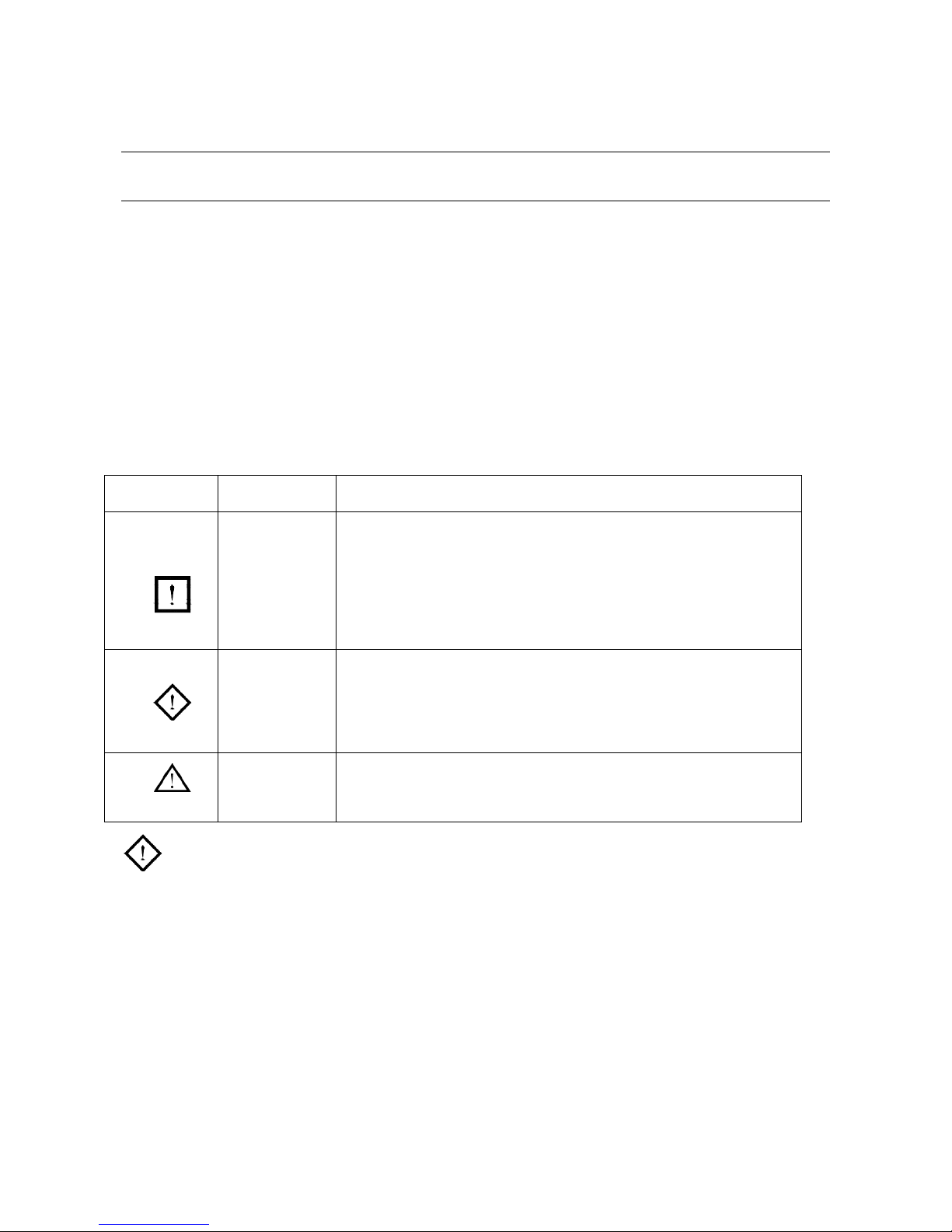
Warning sign
Description
Meaning
High-danger
“High-danger” means there is possibility of severe dangerous, and
may cause dead if not avoid. This sign is used in extreme case,
which is normally related to body dangerous neither than property
loss.
Danger
“Danger” means there is possibility of dangerous situation, and
may cause badly hurt if not avoid. It can also refer to property
loss.
Notes
This means it may cause body hurt if not avoid. Please refer to
the related description when this sign occurred.
Danger! Please follow the rules below in case of bad accidents:
1. Do not use the machine in none-welding areas.
2. The machine is safety considered designed, please do read the warning notes carefully in case of
dead or other bad accidents.
3. Follow related regulations for the construction of the input drive force, selection of the setup place,
usage of the high-pressure gas, storage and configuration, safe-keeping of the workpiece after
welding and management of the offal etc.
4. No entry of unrelated person to the welding area.
USER MANUAL - 4 - YF-74L A2
5. People using heart pacemaker cannot get close to the welding machine and area without the doctor’s
permit. The magnetism caused when connecting the machine will cause influence to the pacemaker.
6. Ask profession person to install, check and maintain the machine.
7. Please correctly understand the contents of this manual to ensure safety, and ask those professional
people with safety knowledge and technique to operate the machine.
Danger! Please follow the rules below in case of electric shock:
*Any contact of electric parts may cause fatal electric shock or burnt.
1. Don’t touch any electric parts.
2. Ask professional person to connect the machine and workpiece to the ground.
3. Cut off the power box before the installation or checking, and restart after 5 minutes. For the
capacitance is chargeable, please ensure it has no voltage before restart even if the power source is
cut off.
4. Do not use cable without enough section or with worn-out cover or broken conductor.
5. Do ensure insulation at the cable joint parts.
6. Do not use the machine when the housing is off.
7. Do not use broken or wet insulation gloves.
8. Use safety net when work at high position.
9. Check and maintain regularly, don’t use it until the broken parts are fixed well.
10. Cut off all the input power when not use.
11. Follow the national or local related standard and regulations when using the AC/DC machine at
narrow or high position.
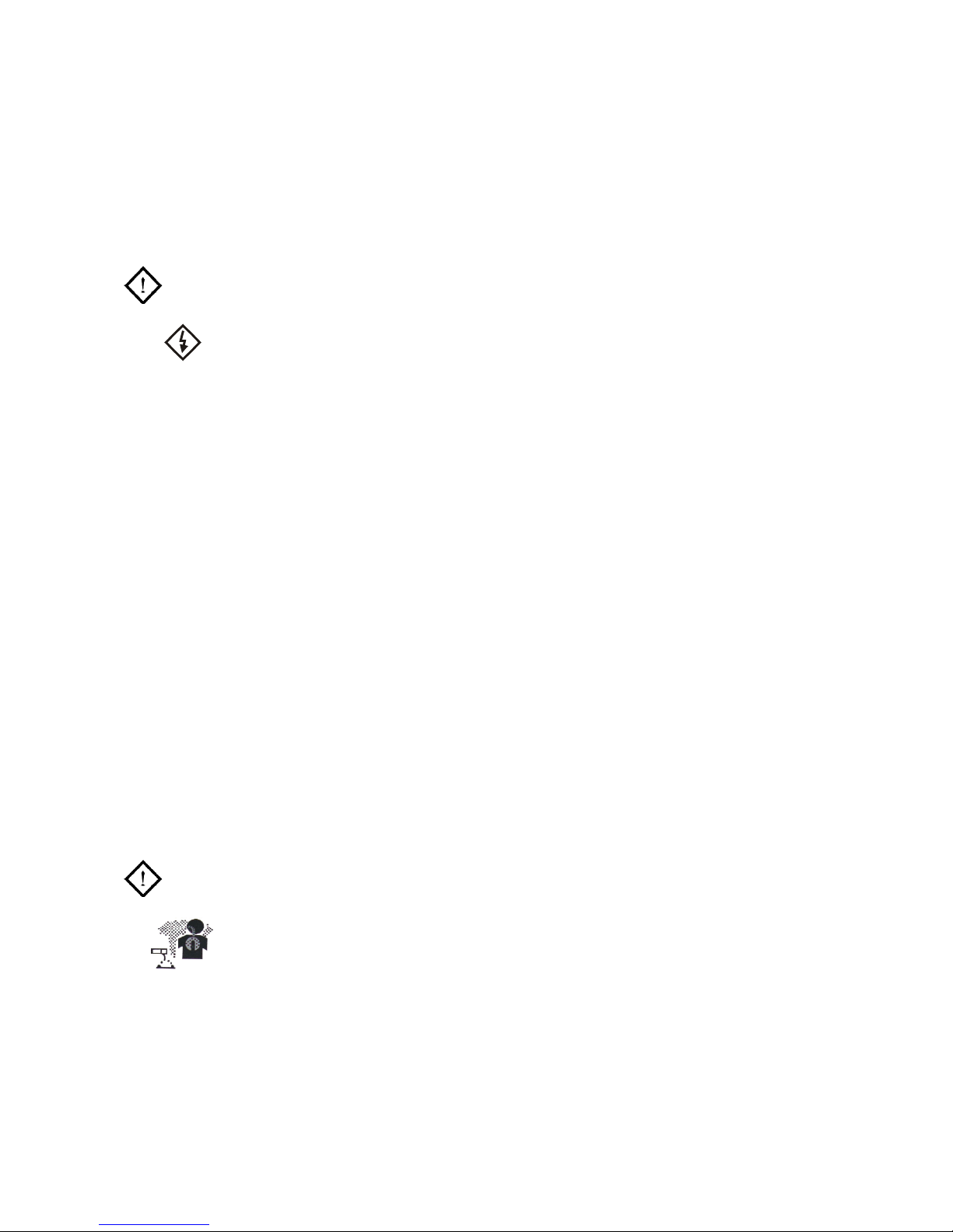
Danger! Please use preventive measures to avoid gas and fumes.
*Gas and fumes are harmful to health.
*It may cause choke when operate in narrow space.
1. In case of accidents like gas poisoning or choke, please use suggested exhaust equipment and
breathe preventive facilities.
2. In case of hurt and poisoning by gas and other powder, please use suggested part exhaust
equipment and breathe preventive facilities.
USER MANUAL - 5 - YF-74L A2
3. When operated on trunks, boilers, cabins etc.,the CO2 and argon gas will stay in the bottom. Please
replace gas sufficiently and use gas respire facilities in case of oxygen shortage.
4. Please accept the supervisor’s check when operate in narrow space, and ensure enough gas supply
and use breathe preventive facilities.
5. Do not weld in degrease, washing and spray space.
6. Use breathe preventive facilities as it will cause poisonous dust and gas when weld shielded steel.
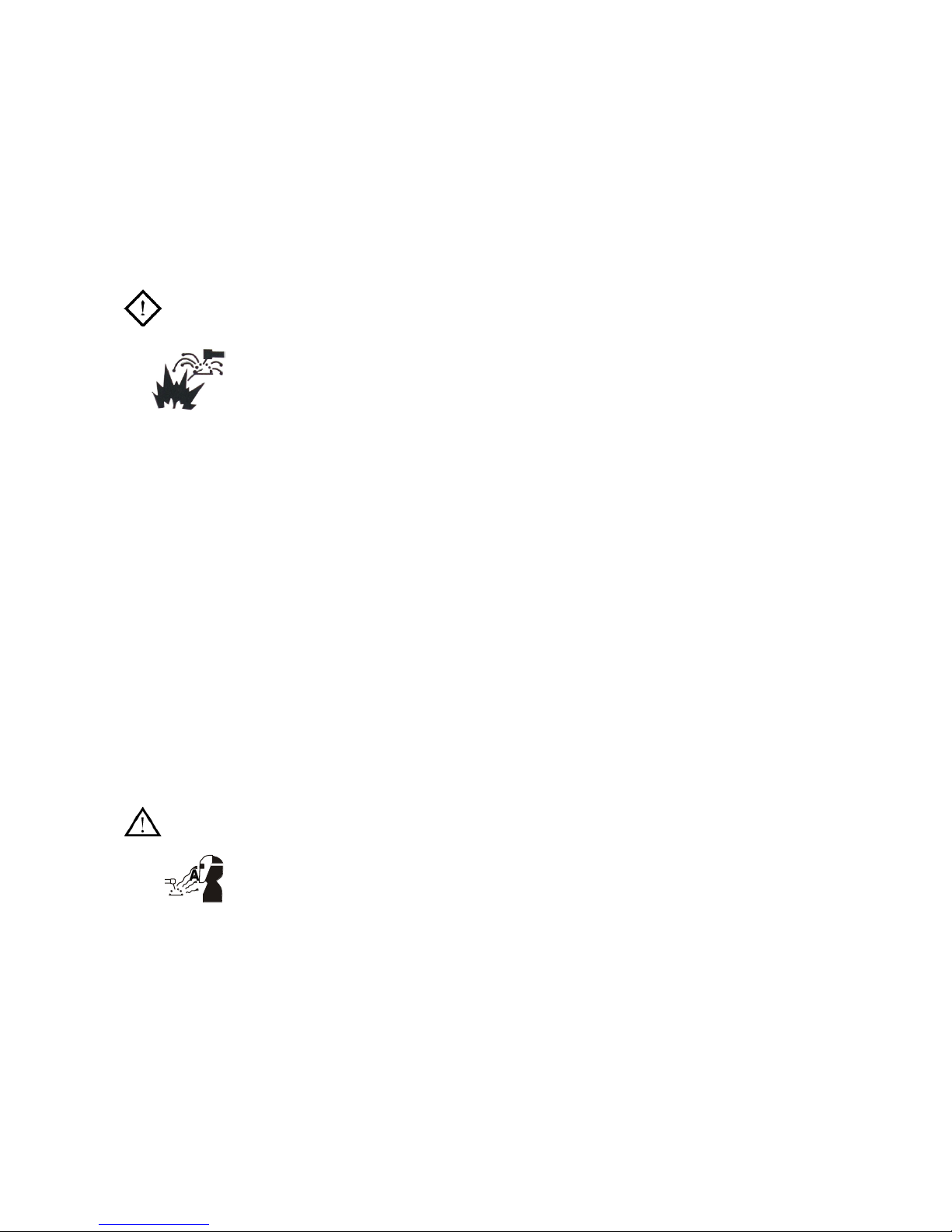
Danger! Please follow the below notes to avoid accidents like fire and explode:
*Spark and hot workpiece can cause fire.
*It may cause fire if the cable is not connected well or when the current circuit of
the steel or other workpiece are not connected completely.
*Do not weld on the case of tinder stuff, or it may cause explode.
*Do not weld airtight containers such as slot, pipe etc., or may break.
1. Do not put tinder stuff in welding area.
2. Do not weld around tinder gas.
3. Do not put heat workpiece near the tinder stuff.
4. When weld the dooryard, ground and wall, do move away the tinder stuff around.
5. The cable joint place should be insulated.
6. The cable joint of the workpiece should be close enough to the welding place.
7. Do not weld those facilities with gas pipe or airtight slot.
8.Put fire extinguisher around the welding area in case of fire.
Notes! Please wear protective appliance to avoid arc, spark, residue and noise.
* Arc ray can cause eye inflammation or skin burnt.
*Spark and residue will burn your eyes and skin.
1. When welding or supervise welding, please use preventive facilities with enough shielding.
2. Please wear preventive glasses.
3. Please wear preventive facilities such as leather gloves, coat, foot-safeguard and apron.
4. Set preventive shield screen around the welding area to protect other people from harmful arc rays.

USER MANUAL - 6 - YF-74L A2
Notes! Please follow the below notes to avoid gas cylinder toppling over or broken.
*Toppling over of the gas cylinder will cause body hurt.
* Wrong use of the gas cylinder will lead to high-pressure gas eruption and
cause human hurt.
1. Use the gas cylinder correctly.
2. Use the equipped or recommended gas adjustment.
3. Read the manual of the gas adjustment carefully before using it, and pay attention to the safety
notes.
4. Fix the gas cylinder with appropriative holder and other relative parts.
5. Do not put the cylinder under high temperature and sunshine.
6. Do not put your face close to the gas cylinder exit when opening it.
7. Put on the gas shield when not use.
8. Do not put the torch on the gas cylinder or touch the electrode.
Notes! Any touch of the switch part will cause injury, please pay attention to the below
notes:
* Do not put fingers, hair, clothes etc. near to the moving parts such as the fan.
1. Do not use the machine when the housing is off.
2. Ask professional person to install, operate, check and maintain the machine.
3. Do not put fingers, hair, clothes etc. near to the switch parts such as the fan.
Notes! Follow the below note as the wire end may cause body hurt:
* The wire shoot out from the torch can stab eyes, face and other naked parts.
1. Before feeding the wire, do not look into the electric conduction hole, or the wire shooted out may
stab your eyes and face.
2. When feeding the wire manually or press the torch, do not put the torch end near to your eyes, face
and other naked parts.

USER MANUAL - 7 - YF-74L A2
Notes! Follow the below notes to ensure better work efficiency and power source:
* No person under of in front of the machine when swing in case of injury!
1. Precautions against toppling over.
2. Warning against the use of welding power source for pipe thawing.
3. Lift the power source from two sides when use the up-down forklift truck in case of toppling over.
4. When using the crane for lift, tie the rope to the ears with an angle no more than φ15 to the vertical
direction.
5. If the machine is equipped with gas cylinder and wire feeder, download them from the power source
and ensure the horizontal of the machine. Do fix the gas cylinder with gallus or chain when moving it
in case of body hurt.
6. Ensure fastness and insulation when using the swing ring to lift the wire feeder in welding.
7. If the machine is equipped with gallus or handles, they are only for hands not for crane, fork-lift truck
or other swing equipments.
Notes for electromagnetism disturb:
1. It may need extra preventive measures when the power is used in some partial space.
2. Before the installation, please estimate the potential electromagnetism problems of the environment
as follows:
1) Upper and down parts of the welding equipments and other nearby power cable, control cable,
signal cable and phone cable.
2) Wireless electric as well as TV radiation and reception equipment.
3) Computer and other control equipments.
4) Safety-recognition equipment etc. Eg: supervise of industrial equipments.
5) Health conditions of the people around. Eg: use of the heart pacemaker and audiphone.
6) Equipments for adjustment and measurement.
7) Anti-disturb capability of other used equipments .Users should ensure these equipments and the
environment are compatible, and this may need extra preventive measures.
8) Practical state of the welding and other activities.
3. Users should follow the below notes to decrease radiation disturb:
1) Connect the welding equipments to the power supply lines.

USER MANUAL - 8 - YF-74L A2
2) Maintain the welding equipments regularly.
3) The cable should be short enough to be close to each other and near to the ground.
4) Ensure the safety of all the metal parts and other parts nearby.
5) The workpiece should be well connected to the ground.
6) Shield or protect the other cable and equipments to decrease the influence of disturb. The welding
equipments can be fully shielded under special conditions.
4. Users are responsible for the disturb problems caused by welding.
PRODUCT DESCRIPTION
The welding machine applies the most advanced inversion technology in the world.
The principle of inversion is to transform the power frequency of 50Hz/60Hz into direct current and invert it into high
frequency (25KHz) through high-power device IGBT, then perform voltage-drop and commutation with the output high-
power D.C power supply via Pulse Width Modulation (PWM). Since the switch power inversion technology is adopted,
the weight and volume decrease greatly while the conversion efficiency increase of more than 30%
Additional to MIG, the machine has the functions of STICK and TIG. It adopts full digital panel display, which can
realize synergic adjustment of feeding speed and welding voltage as well to regulate the welding parameters easily.
Our CO2 gas shielded welding machine is equipped with unique electronic reactor circuit, which can precisely control the
short-circuiting transfer and mixed transfer resulted in better performance than other machines. Compared with silicon
controlled welding machine and tapped welding, our products have the following advantages: stable wire feed rate,
portable, energy-saving, electromagnetic noise free. Besides, our products spatter less, easier arc starting, deep welding
pool, high duty cycle etc.
Thank your for choosing our products. Please feel free to propose your valuable suggestions; we will make efforts to
perfect our products and service.
WARNING!
The machine is mainly used for industrial purpose. It will cause radio interference indoor, operators
shall take fully preventative measures.

USER MANUAL - 9 - YF-74L A2
TECHNICAL PARAMETERS
Type Item
MIG175GD
Power voltage (V)
1 phase
220V15%
Frequency (Hz)
50/60
Rated input current (A)
28
No-load voltage(V)
56
Output current adjustment (A)
20-175(MMA)
10-175(TIG)
50-175(MIG)
Output voltage (V)
16.5-22.8
Duty cycle (%)
35
Power factor
0.73
Efficiency (%)
80
Type of wire feeder
Internal
Wire feed speed (m/min)
2-12
Post flow time (S)
3
Welding-wire diameter (mm)
0.6/0.8/1.0
Insulation grade
F
Housing protection grade
IP23S
Welding thickness (mm)
More than 0.8
Weight (kg)
12.8
Overall dimension (mm)
420*220*439

USER MANUAL - 10 - YF-74L A2
INSTALLATION INSTRUCTION
The welding equipment is equipped with power voltage compensation device. It keeps the machine work normally when
power voltage fluctuating ±15% of rated voltage.
When using long cable, in order to reduce voltage drop, big section cable is suggested. If the cable is too long, it will
affect the performance of arcing and other system function, it is suggested to use the recommend length.
1. Make sure the intake of the machine is not covered or blocked to avoid the malfunction of the cooling system.
2. Use ground cable whose section no less than 6mm2 to connect the housing and earth. The method is to connect the
grounded interface in the back to the earth device, or make sure the earth end of power interface has been reliably
and independently grounded. Both ways can be used together for better security.
MIG 175GD Installation Procedures:
1、Correct Installation of MIG:
1) Connect the gas cylinder with CO2 decompression flow mete tightly to CO2 mouth behind the machine via air tube.
2) Insert the swift plug of earth cable into socket at the front panel.
3) Set the wire wheel with wire on the wheel axis, the wheel hole should be matched with the wheel fixer.
4) Choose wire slot according to wire size.
5) Loosen the screw of wire-pressing wheel, pit the wire into slot via wire-lead tube, adjust the wire-pressing wheel to
keep wire fix from gliding, but strength should be suitable in case the wire distorts and affects wire sending.
6) Wire roll should turn clockwise rotation to let out wire, to prevent wire from gliding; wire is usually set to the fixed hole
on the wheel side. To prevent the bent wire from getting stuck, please cut off this part of the wire.
7) Put and tighten the torch on the output socket and put the wire into the torch by hand.
2、Correct Installation of LIFT TIG:
1) Connect the shielded-gas source correctly. The gas supplying route shall include gas cylinder, argon decompression
flow meter and gas pipe. The connecting parts of the gas pipe should be fastened by hose clamp or other objects, in
order to prevent leakage and air-in.
2) Connect the plug of TIG torch to “-“of the front panel, and fasten it clockwise.
3) Connect the plug of TIG torch to the relative interfaces of panel and fasten the screw.
4) Connect one end of the earth clamp cable to “+” of the front panel, and fasten it clockwise, the other end clamp the
workpiece.
 Loading...