

Page 1
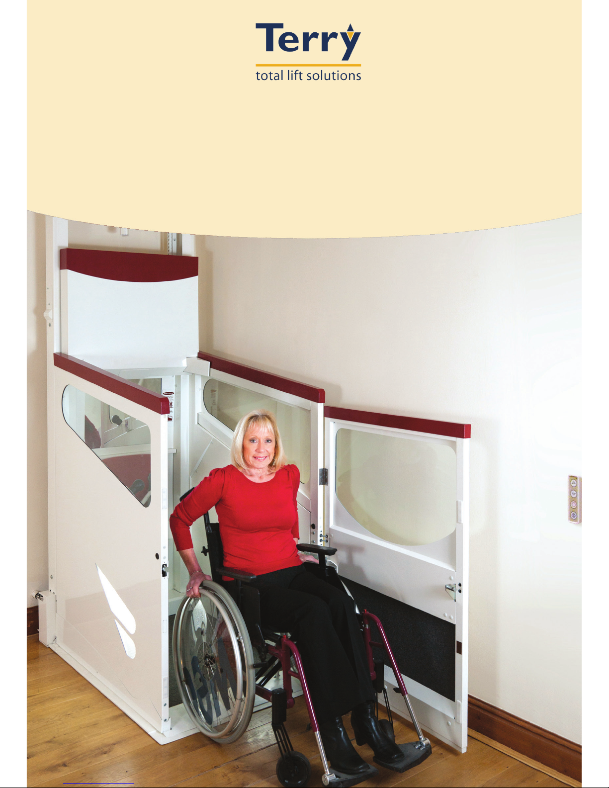
USER MANUAL
Harmony Series 2 Homelift
Through Floor Lift
Original instructions
Page 2

CONTENTS
Introduction 4
Description 5
General Do’s and Don’ts 6
Controls and Operation 8
Smoke Alarms 10
Emergency Procedures 12
Fault Finding 14
Changing Smoke Alarm Batteries 16
Changing Call Station Batteries 17
Safety Feature Check 18
Lift Disassembly / Safe Disposal of Hazardous
Materials
19
Service History Record 20
Declaration of Conformity 21
Lift Specication Sheet 22
3
Page 3

4
INTRODUCTION
Thank you for choosing the Harmony Lift, designed and
manufactured in the U.K. using the latest technology by Terry
Group Ltd. We want you to get the most out of your Harmony Lift
and to help in this aim we have produced this small booklet on
operation and maintenance of the equipment, which we hope you
will find helpful.
It is hoped that any queries you may have during day to day
operation will be answered in the text, but if you do have any
problems, technical assistance is only a phone call away.
We hope our product gives you many years of reliable service.
Peter Morrey
Managing Director
Page 4

5
DESCRIPTION
The Harmony Homelift ‘N’ is an inter floor lift that is designed for
use by persons with impaired mobility travelling between fixed
floor levels in private dwellings.
With a maximum carrying capacity of one person, with or without
a wheelchair, this lift is not intended for use as a means of
transporting goods.
The lift is designed to operate without a lift shaft and is provided
with an automatic infill panel which makes the ceiling aperture
safe when the lift is parked downstairs.
An optional telephone can be supplied in the car for emergency
communication.
A standard feature is the provision of half hour fire rated panels in
both the aperture infill and the car underpan.
The lift car panels are made from powder coated steel which can
easily be cleaned using normal household cleaners. Upholstery
is made from PVC and can be cleaned in the same way.
A smoke detection system has been installed on your lift. It has
been designed to provide adherence to British Standard BS5900
2012 Section 9.13 “Behaviour of homelift in the event of fire”.
Page 5

GENERAL DO’S AND DON’TS
• Never switch off the power supply to the lift, even when you go away. The
lift control circuits are fed by a battery, which must be kept on constant
charge.
• The lift should always be returned to the lower level when not in use. If
it is left upstairs for prolonged periods, it will occasionally re-level itself
depending on conditions. The lift must be left at the lower level if the
mains is turned off.
• If your lift is fitted with a manual door always close it after use. Powered
door units have a self closer. Do not pull or push the automatic door.
• Never allow children to play in, under or around the lift. If children are in
the house, isolate the lift using the optional remote control fob, see pg 8.
• Ensure that the area under the lift is kept clear. The underpan surface is
fitted with sensors, which automatically stop the lift if it strikes an object
(see Fig.1).
• Always keep your emergency door release key and key fob in the lift or in
a safe place near the lift.
• Do not place any object on the aperture infill or stand on it when the
lift is in operation. Ensure that as far as practical, the area around the
travelling infill panel is clear of persons (particularly children) when the lift
is being operated. This is to ensure there is no danger of them falling into
the car when the lift is in use. The infill panel is fitted with sensors that
automatically stop the lift if the infill panel is obstructed (see Fig.1)
• Do not use this lift for anything other than transporting those with
impaired mobility between fixed floor levels
• Do not lean over the car sides or door. These are fitted with safety edges
which will stop the lift if activated.
• Always treat your lift with respect that should be shown to electrical and
mechanical equipment.
• Users with wheelchairs should apply the brakes on their chair and all
other users should ensure they are using the seat provided before
moving the lift. Do not travel in the lift unless seated.
• Safety related components should only be adjusted and reset by a
competent person.
6
Page 6
7
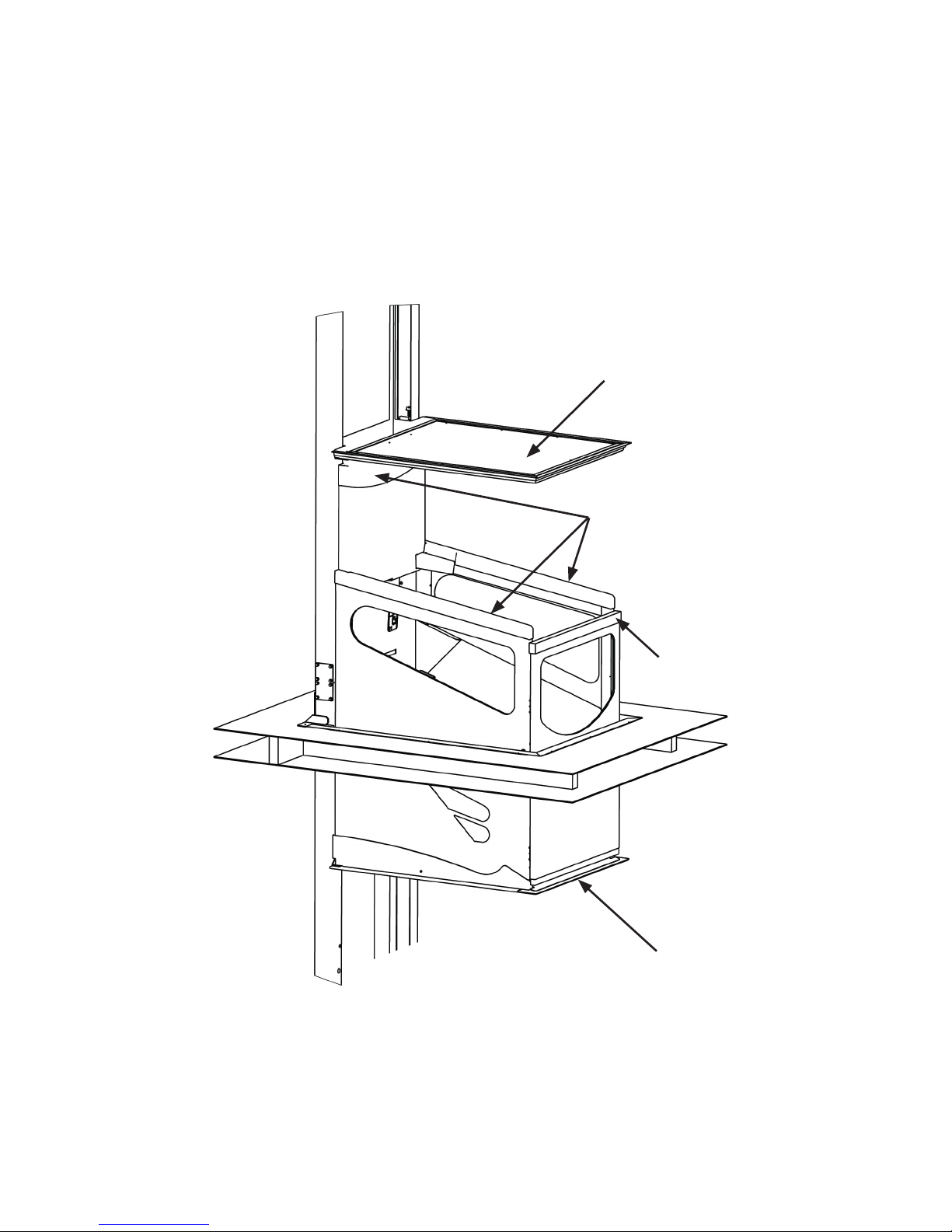
Proceed with caution when exiting the carriage backwards
The diagram below (Fig.1) shows the position of all the sensors
on the lift, designed to prevent injury or damage if the movement
of the carriage is obstructed.
Infil panel safe edge
(sensors on upper
and lower surfaces)
Safe edges
Door safe edge
Underpan safe edge
(sensor on lower and
upper surface)
Fig. 1
Harmony lift shown part-way
through aperture
Page 7
CONTROLS AND OPERATION
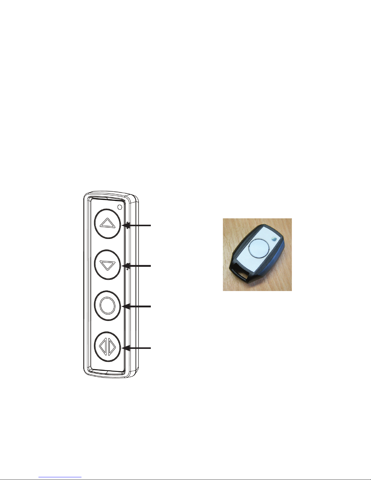
There are two wall mounted call stations, one at each level (see
Fig.2) and a similar control station fitted in the lift car. The lift can
be isolated by using the optional remote control fob. When the lift
is isolated, none of the control stations will function. The call and
control stations can only be activated by using the remote fob.
When the lift is activated, the coloured indicator lights in the car
will illuminate. The lights in the car will switch on automatically
when any call or control button is pressed and will automatically
turn off after a few minutes.
Once the lift has been stopped it cannot be restarted for 3
seconds.
Users with wheelchairs should apply the brakes on their chair
and all other users should ensure they are using the seat
provided before starting the lift.
8
DOWN
DOOR
STOP
UP
Wall mounted call station
Optional remote
isolate fob
Fig. 2
Page 8
General operation
Call the lift by pressing the UP or DOWN button on either call
station and wait for it to stop. The door will automatically open.
Enter the lift and press and release the door button to close it.
Then press and release UP or DOWN on the control station. The
lift will travel uninterrupted to the next floor. If the lift does not
start, check that the door is properly closed and try again. Always
close the door after using the lift by pressing the DOOR button on
the wall mounted call station. The lift should always be returned
to the lower level when not in use.
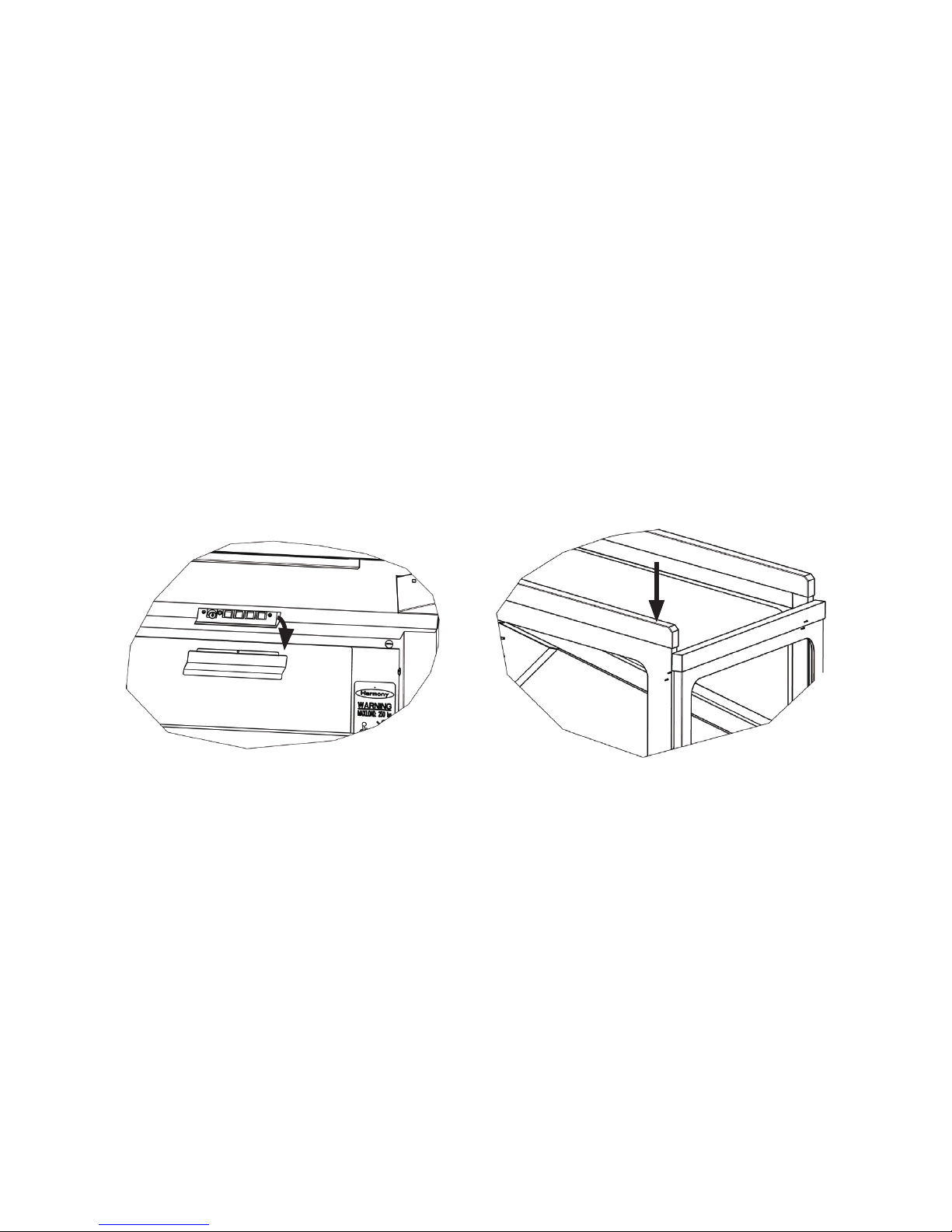
In the event that the normal controls fail to work, emergency
controls can be found under the flap above the mirror. Green is
‘UP’, red is ‘STOP’, black is ‘DOWN’ and white is ‘DOOR’. See
Fig.3
When outside the car, in an emergency the door can be opened
by pressing the front end of the side safe edge, on the corner
where the door opens (See Fig.3a).
9
Fig. 3 Fig. 3a
Page 9

SMOKE ALARM
A smoke detection system has been installed on your lift. It has
been designed to provide adherence to British Standard BS5900
2012 Section 9.13 “Behaviour of homelift in the event of fire”.
The system utilises two smoke alarms one upper level, one lower
level, which are wirelessly connected to the main circuit board on
the lift (see illustration below).
The Smoke Alarm unit comprises two parts, the first (TOP PART)
being a Smoke alarm unit. This is the Smoke detection unit and
contains an integral battery with a 10 year life span. This is not
replaceable.
The second part (BASE UNIT) contains the radio transmitter
receiver unit. Power to this unit is supplied by two AA style
Lithium batteries. The voltage level of the batteries is monitored.
In the event of a low battery, a sounder in the carriage will beep
(see Fault Finding pg.14). If the batteries are not replaced, the lift
will be taken out of service.
Radio smoke alarm operation
When installed on a Harmony Lift, the smoke alarm system will
cause the lift to deactivate safely once the alarm is triggered.
When deactivated, the door will continue to operate as normal.
Mute/test button
Smoke Alarm (TOP PART)
Radio Transmitter/receiver
Unit (BASE UNIT)
10
Page 10

When the Lift is stationary at either level:
If smoke is detected, the alarm will sound. After a period of time,
all other smoke alarms connected to the system will then start to
sound and the lift deactivates.
When the Lift is travelling between levels:
If smoke is detected, the alarm will sound. After a period of time,
all other smoke alarms connected to the system will then start to
sound.
The lift will continue to its requested level, it will remain possible
(until that level is reached) to change the direction of the lift.
Once at the desired level, the lift will deactivate.
Reactivation of Lift
The lift will automatically reactivate when the smoke alarm no
longer detects smoke and a period of two minutes has expired.
Silencing the Smoke Alarms
In either situation, it is possible that the sounder of each
individual alarm can be silenced. The alarms that has been set
off remotely can be silenced by pressing the both the STOP and
DOOR button on one of the lift handsets. Then the alarm that
has been triggered by the smoke can be silenced by pressing
the mute button on the alarm itself. Doing this will silence the
alarms for four minutes. When silenced, the lift will automatically
reactivate when a period of two minutes has expired. If the
source of smoke is not removed, the smoke alarms will begin to
sound again and the lift will be disabled.
11
Page 11

12
EMERGENCY PROCEDURES
In the event of a mains failure during travel, the battery backed
control system of the Harmony will allow normal operation in the down
direction without loss of any safety features. This allows the user to exit
the car at the lower level in the normal way.
Emergency Manual Lowering
IMPORTANT:
During emergency manual lowering, the normal safety features will not
function, so the lift will not stop if a person, pet or object is under the
lift.
• The exact lowering procedure must be observed, because the normal
safety features will not function during manual lowering.
• The emergency lowering procedures should never be used if the lift is
fully up or no one is trapped in it.
• The emergency lowering procedures should also never be used as
the normal down travel function until an engineer attends.
PLEASE NOTE:
If the lift is fully upstairs and a person is trapped inside, please see the
section Emergency unlocking (see pg13).
If the lift has stopped mid level and the customer is unable to get the lift
up or down then the only time it should be lowered by the emergency
valve is if:
• There is a second person (B) around the lift area at the lower level to
ensure that nothing goes under the lift during the lowering by the first
person (A);
• OR the person lowering the lift has sight of the area under the lift .
Person A
• Ensure the door is fully closed.
• Turn the mains supply to the lift off.
• Locate the hydraulic power unit, normally outside the property (see
Fig. 4).
• Swivel the small metal cover plate on the front face of the housing to
reveal an access hole (see Fig. 4).
• The red cord revealed in the access hole now needs to be pulled
continuously to lower the lift car slowly.
Page 12

13
• After 5 seconds release button and check with person B that the trap
door is following the carriage. If so continue to lower
• Once the lift is at the lower level turn the mains supply back on.
Person B
Remains in the house by the lift and communicates with Person A to
ensure the safe lowering of the lift.
• Ensure that no object, person or pet are in the path of the lift travel
• Confirms that the trap door follows the lift during descent and locates
fully in the floor to guard against the possibility of anyone falling down
the lift way.
Emergency unlocking
WARNING: RISK OF FALLING – Emergency unlocking must only
be undertaken when the lift is at the upper or lower landing level.
The lift car door is designed so that it will only open when the lift is at
or within 25mm of each floor served. If for any reason the door cannot
be opened, the door lock can be over-ridden from the inside using the
following steps:
• Remove the black rubber grommet by the door.
• Insert the black emergency door release key into the square hole
behind the grommet.
• Turn the key to release the mechanism.
This should release the catch. The door can be opened from the
outside in the same way.
The electrically operated door on the wheelchair model can be forced
open or closed manually. This will disengage the door from the opening
mechanism and require re-setting of the door. Re-setting of the door
can be done as follows:
Remove the screw using the
screwdriver provided at installation.
Swivel this metal plate to one
side in order to gain access to the
lowering string behind the plate.
Indicates mains power to lift
(usually ‘on’ red).
Fig. 4
Page 13

Battery warning (red) This
is normally off, but may be
on during operation.
This is OK providing it
extinguishes eventually
when lift is at either level
DOWN CAR (yellow
light). Means safe edge
car OK. Will be off when
ascending and when at
lower level.
UP CAR (green light)
Means safe edge car
OK. Will be off when
descending.
DOWN TRAP (yellow
light). Means safe edge
in fill panel OK. Will be
off when ascending.
UP TRAP (green light)
Means safe edge infill
panel OK. Will be off
when descending.
Fig. 5
• Manually close the door as far as possible.
• Press and release the door button.
• Move the door back and forth until it clicks.
• Press and release the door button again.
The door should now operate normally, otherwise repeat the
above process.
FAULT FINDING
The most likely causes of your lift failing to operate are:
• No mains power supply
• The door not being fully closed.
• Something obstructing the travel of the car or in fill panel
causing one or more of the sensors or safe edges (see Fig.1)
to operate and therefore preventing travel in the appropriate
direction.
To assist in identifying the cause the car if fitted with a simple
system of coloured indicator lights on the rear panel, one red, two
yellow and two green (see Fig.5).
14
Page 14

Lift Malfunction
Fault Indication Cause Remedy
No lift function at all. No red LED on
powerpack cover.
No mains power to
the lift.
Check mains is on
and reset RCD/Spur
if required.
Lift will not travel in either
direction.
No lights on car
panel.
Door not shut or
remote fob o.
Press door button
Press button on fob.
Flat batteries in
smoke alarms.
Replace smoke
alarm batteries.
Lift will not go up. One green o on
car panel.
Car safe edge
obstruction.
Remove obstruction
or free safe edge.
Both greens o on
car panel.
Inll panel obstructed
on upper surface.
Remove obstruction
from upper surface.
Lift will not go down. One yellow o on
car panel.
Car underpan
obstruction.
Remove obstruction
from beneath
surface.
Both yellow o on
car panel.
Inll panel obstructed
on lower surface.
Remove obstruction
from lower surface.
Powered door will not
close fully.
Can be moved
easily by hand.
Door has disengaged
from drive
mechanism.
See pg 13 & 14
Person B emergency
unlocking.
Smoke Alarm Malfunction
Indication Cause Remedy
Alarm beeps twice every 45 seconds. Unit Malfunction. Call an engineer.
Alarm does not sound upon pressing test
button.
Unit Malfunction. Call an engineer.
The operating light remains steadily on or off
(ie. Does not flash approximately once every 45
seconds when unit not in alarm).
Unit Malfunction. Call an engineer.
Low Battery Warning
Indication Cause Remedy
Single short beep on lift car every 2 minutes. Low Handset battery. Replace CR2450
batteries in handset.
Double short beep on lift car every 2 minutes. Low smoke alarm
battery.
Replace AA batteries
in smoke alarm.
Double long beep on lift car every 2 minutes. Smoke alarm battery
dangerously low.
Replace AA batteries
in smoke alarm.
Lift will not travel in either direction. Smoke alarm
batteries flat.
Replace AA batteries
in smoke alarm.
15
Page 15

CHANGING SMOKE ALARM BATTERIES
1. To change the batteries push upwards
on this part of the alarm base with any
small tool, then turn alarm clockwise.
2. Unscrew the alarm base plate from
the box
3. Fit the two AA style Lithium
batteries into the board battery
holder as shown.
16
Page 16

17
CHANGING CALL STATION BATTERIES
CR2450 (550 mAh minimum) are approved for use with these
devices.
CRITICAL:
• It is critical that all three batteries are replaced with new ones of
the same type, manufacture and age, that they are fitted at the
same time and that they are correctly oriented.
1. The call station can be
removed from the wall by
sliding the case upwards.
2. Remove the four screws in
the back with a posi-drive
screwdriver.
3. Using a screw driver, gently
push the battery out a short
way and then pull using
fingers.
Page 17

SAFETY FEATURE CHECKS
AS A PRECAUTIONARY MEASURE WE ADVISE PERIODIC
(WEEKLY) CHECKS OF THE SAFETY FEATURES BUILT INTO
YOUR HARMONY INTER FLOOR LIFT AS FOLLOWS:-
(see Fig.1)
1 CARRIAGE SIDES AND DOOR UPPER SAFE EDGE
With the lift at lower level, press the UP button on the wall
station, when lift starts to ascend press downwards on
carriage side upper surface, the lift should stop.
Lower the lift to floor level and repeat operation with other
carriage side and door.
2. CARRIAGE UNDERFLOOR SAFETY UNDERPAN
With the lift at approximately eye level press the DOWN
button on wall station, when lift starts to descend press
upwards on the carriage underpan, the lift should stop.
Raise lift and if possible, repeat operation on opposite
side of lift.
THESE CHECKS SHOULD BE CARRIED OUT WITH THE LIFT
UNOCCUPIED
If any of the above checks fail, the lift MUST NOT be used and
advice sought from Terry Group Ltd.
Servicing & Maintenance
This lift should be serviced at least every 12 months. This service
should be conducted by competent persons trained in servicing
and repair of the product.
18
Page 18

19
Lift Disassembly/Safe Disposal of
Hazardous Materials
This lift must be disassembled by a competent person who has
been fully trained in the installation of this lift and is qualified to
provide safe disconnection of the lift to the mains terminal.
Batteries & Printed Circuit Boards (PCB)
The batteries and PCB’s within this product should not be
disposed of with other household waste at the end of their
working life. Where batteries are marked with the chemical
symbols Hg, Cd or Pb, it indicates that the battery contains
mercury, cadmium or lead above the reference levels in EC
Directive 2006/66. If batteries are not properly disposed of, these
substances can cause harm to human health or the environment.
Batteries and PCB’s that are no longer required for this lift, at the
end of their working life, can be returned either to an approved
waste disposal facility or to Terry Group Ltd for safe disposal.
Oil
Oil from this lift should be disposed of via an authorised waste
disposal contractor or to an approved waste disposal facility.
Page 19

SERVICE HISTORY RECORD
An entry should be added to the following table every time the lift
is serviced.
Date Engineer Company Comments
20
Page 20

21
DECLARATION OF CONFORMITY
Lift Type: Harmony Lift
This lift was manufactured by TERRY GROUP Ltd., who declare that this lift fulfils all
the relevant provisions of the following Directives:
2004/108/EEC Electromagnetic Compatibility Directive
2006/42/EC Machinery Directive
This lift also fulfils all the relevant provisions of the following Standards:
BSEN 12015:2014 Electromagnetic compatibility. Product family
standard for lifts, escalators and moving walks.
Emission.
BSEN 12016:2013 Electromagnetic compatibility. Product family
standard for lifts, escalators and moving walks.
Immunity.
BS5900:2012 Powered homelifts with partially enclosed
carriers and no liftway enclosures – Specification
Person authorised to compile Technical File:
Greg Gnyp, Terry Group Ltd., Longridge Trading Est, Knutsford, Cheshire, WA16 8PR.
EC examination carried out by: Bureau Veritas UK Ltd., Parklands, Wilmslow Road,
Didsbury, Manchester, M20 2RE.
Notified Body Reference Number:0041
EC examination certificate number: CE-0041-MD-TER001-10-GBR
This declaration was completed at Terry Group Ltd., Longridge Trading Estate,
Knutsford, Cheshire, WA16 8PR, in August 2014.
This compliance is only valid if the installation test Certificate has been completed
and signed by a competent lift engineer trained to install this product to the latest
installation instructions.
TERRY GROUP Ltd.
P.Morrey (Managing Director)
Page 21

LIFT SPECIFICATION
Address of manufacturer:Terry Group Ltd.,
Unit 1 Longridge Trading
Estate,
Knutsford,
Cheshire,
England,
WA16 8PR.
Lift serial No: Year of manufacture:
Safe working load: Harmony S & W = 280kg
Harmony L & LW = 250kg
Maximum travel: 3.6 metres
Duty cycle: 10 cycles per hr with max load
Average noise level: 65 dB
Power supply: Dedicated 240V ~ 50/60 Hz
single phase supply
Control voltage: 12V DC
Hydraulic pump power
consumption:
1200W maximum
Hydraulic oil grade: T22
Hydraulic pump enclosure: IP54
Designed and manufactured
to:
BS5900:2012
Fire specification: Half hour fire integrity through
aperture, Exova Warrington Fire
Research assessment
No. 320925
22
Page 22

23
Page 23

24
Page 24

Ref: ED00052J
For technical help,
sales or service enquiry telephone:
This Harmony Lift has been manufactured by:
Terry Group Ltd.
Longridge Trading Estate,
Knutsford, Cheshire, WA16 8PR.
t: 0345 365 5366
e: sales@terrylifts.co.uk
w: www.terrylifts.co.uk
Certicate Number 13858
ISO 9001, ISO 14001,
OHSAS 18001
 Loading...