

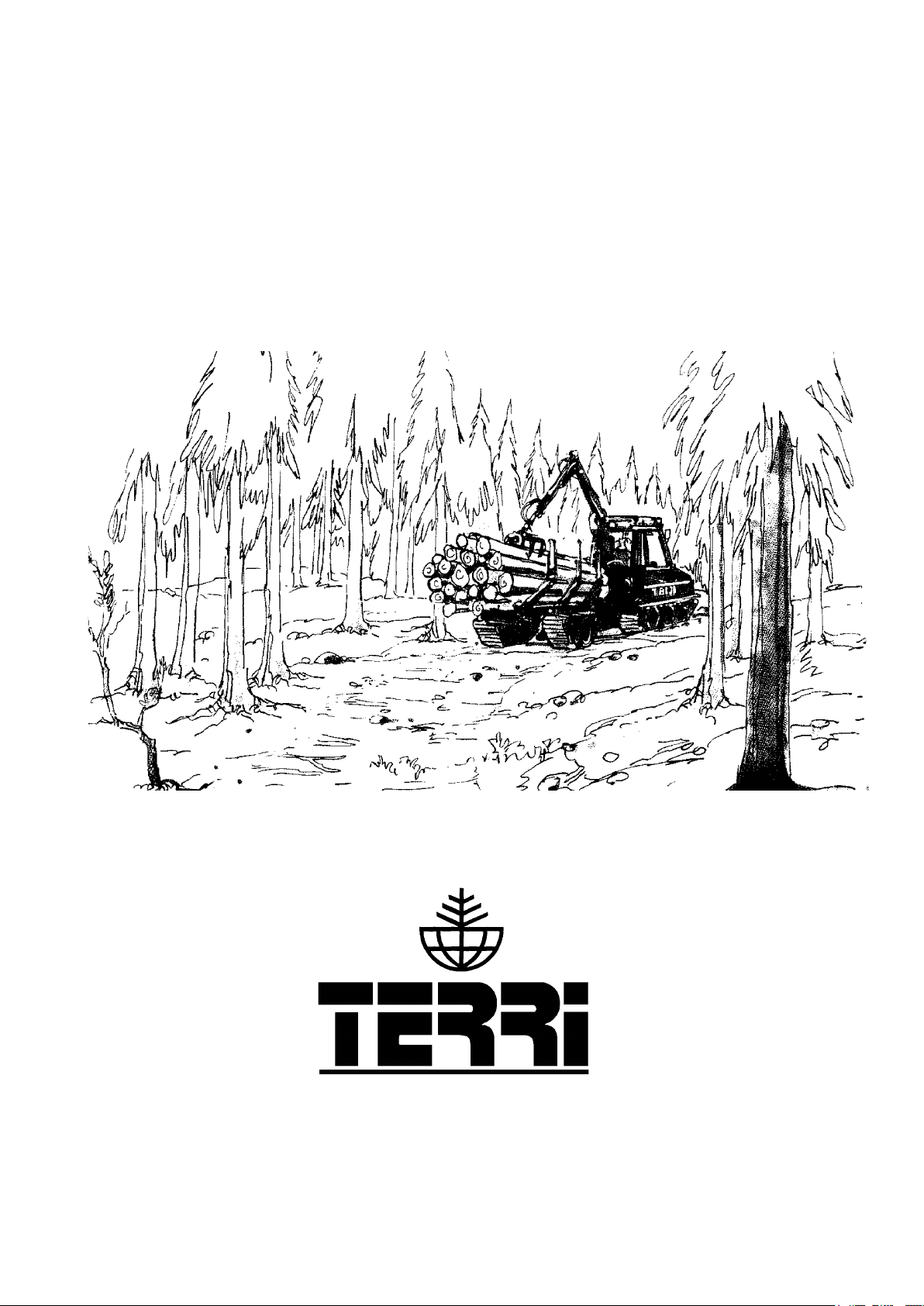
Terri 2040 Instruction Book
Instruction book
From 199561010
2040
604732
1

Foreword
By studying this Manual you will learn how to
operate and look after your new Terri 2040. For
those of you already familiar with Terri, this
Manual also contains certain information which
you must know.
Apart from lubrication and simpler maintenance
tasks, which you can easily do yourself, you
should let your dealer, who has trained personnel,
be responsible for the servicing.
We reserve the right to change without previous
notice data and equipment, as well as maintenance
and other service instructions.
Manufacturer: Tranells Heby Terrängfordon
THT AB
S-744 31 HEBY, Sweden
Tel: +46-224- 341 40
Fax: +46-224-318 95
Machine type: TERRI 2040
Machine nameplate:
front of the engine
compartment
Serial number: .............................
Engine number; .............................
Located to the left in the
2

ICONTENTS
1 Foreword
1 Manufacturer
1 Machine nameplate
1 Serial number
2 Contents
3 Description
4 Safety
5 Working close to overhead lines
6 Main components of Terri 2040
7 Instrumentation and controls
8 Front dashboard
8 Rear dashboard
15 Driver’s seat
16 Driving instructions
18 Maintenance
18 Diesel engine
20 Fuel system
21 Air lter
22 Cooling system
23 Electrical system
25 Hydraulic system
26 Hydraulic oil tank
27 Tracks-Bogie system
29 Brakes
30 Winch
31 Gearbox
32 Trailer adjustments
33 Lubrication
34 Recommended lubricants
35 Maintenance schedule
36 Troubleshooting
37 Technical specication
39 Alphabetical index
3

DESCRIPTION
TERRI 2040
Terri 2040 is a articulated-steered off-road tracked vehicle (forwarder), with a load capacity of 1.2 m².
Terri 2040 is a special machine with a wide and versatile range of applications.
A 3-cylinder Kubota D1105 diesel engine with precombustion chamber is used as power source in Terri
2040.
Terri 2040 has a hydrostatic/mechanical transmission with a closed hydraulic circuit. The system is
driven by a power-limited variable hydraulic pump, which is directly coupled to the diesel engine. In the
trailer a high-speed hydraulic motor drives a 2-speed preselector gearbox with mechanical differential
lock. The gearbox drives the tracks via two sprocket wheels.
Terri 2040 is easy to operate, having smooth driving charactristics and providing a substantial pulling
power in all situations. The closed hydraulic system is just as effective as a brake as a power unit, when,
for example, the forwarder is driven with a full load down a slope.
The safety cab is spacious and the controls used during normal work are in easy reach of the driver. The
number of functions needed to operate Terri 2040 has been reduced to a minimum. The driver therefore
sits comfortably when both driving and working. The versatile grab-loader is operated with a conventional multi-stick system. Different driver seats with mechanical or air suspension are available.
At the front of the machine there is a built-in winch. This can be used to pull the machine loose or to haul
timber from inaccesible terrain.
TRAILER WITH HYDRAULIC DRIVE
The trailer has two low-speed hydraulic motors, which drive the tracks via sprocket wheels. It is
equipped with an automatic hydraulic differential brake. An electric switch in the cab is used to engage
and disengage the trailer drive. When the trailer drive is disengaged, the hydraulic motors are disconnected at the same time from the load, which enables the trailer to move freely. The highest transport speed is
obtained with the trailer drive disengaged and the gearbox in top gear engaged. The trailer has a built-in
parking brake, which is operated with an electric switch in the cab. When the diesel engine is stopped, the
trailer is automatically braked.
Remember that safety always depends on the driver. Therefore always follow the safety instructions
carefully.
4
SAFETY
This chapter summarizes the rules, which must
always be followed when you are working with
Terri 2040. These rules do not exempt the driver,
however, from taking into account statutory or
other valid national regulations and directives concerning trafc safety and industrial safety.
To be on the safe side
Get throughly acquainted with Terri 2040 and its
operating instructions.
Don’t lend Terri 2040 to anybody who is not used
to operating your machine. You may be held responsible for any injury or damage that may occur.
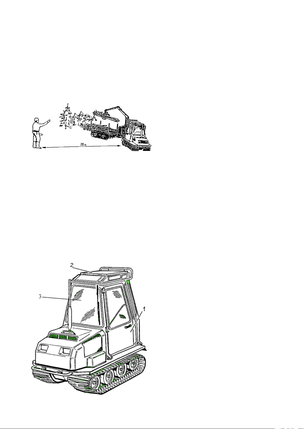
T H E D A N G E R Z O N E I S 2 0 M E T R E S!
Nobody may stay in the danger zone when the
machine is in use.
Terri 2040 does not have any room for a passenger.
Never start the diesel engine, or let it run indoors
in premises with closed doors. Warning for carbon
monoxide poisoning.
If the machine overturns, hold on to the seat or
handles. DON’T JUMP OUT!
Don’t drive the forwarder with a load hanging
from the grab-loader.
Before getting out of your Terri 2040, lower the
gripper, stop the engine and turn off the main
switch.
Don’t walk or stand under a hanging load.
Carry out regularly the maintenance points according to the schedule. Before servicing or checking
the machine, always stop the engine.
Familiarize yourself with the emergency exits in
the cab:
1. Side doors 2. Roof opening
The safety bolts of the roof opening must be
withdrawn when you drive on a lake or river covered with ice.
When checking the level of the fuel tank and the
battery electrolyte, never use a naked ame.
5

If possible, inspect in advance the terrain on the
route to be taken, particularly during the winter,
when snow may cover unevenness in the ground.
Note the slope of the terrain and its inuence on
the stability of the tractor.
Be aware of the total height of the grab-loader and
load, before driving anywhere with height restrictions. Pay particular attention to any temporary
structures, sagging overhead lines, etc.
Never load the trailer above the height of the load
protection.
Never allow children to stay in the cab or in the vicinity of the machine, when the engine is running.
WORKING CLOSE TO OVERHEAD
LINES
When you are working in the vicinity of electric overhead lines, no part of the machine or
the load must come closer to the line than the
distances given in the following:
Low voltage 2 metres
High voltage <40 kV 4 metres
High voltage >40 kV 6 metres
If it is difcult to follow the above-mentioned
safety regulations, contact the owner of the overhead line in order to de-energize it. Under no circumstances whatsoever can you rely on good luck
when working close to an overhead line. Where
applicable, material must be moved by some other
means a sufcient distance from the overhead line
before it is loaded.
When driving in forests and along forest roads,
remember that it is difcult to see an overhead line
crossing the route. In addition, the line may be
sagging heavily due to snow and ice.
ELECTRICITY DOES NOT NEED ANY DIRECT CONTACT. A HIGH VOLTAGE CAN
JUMP ACROSS EVEN LONGER DISTANCES.
6
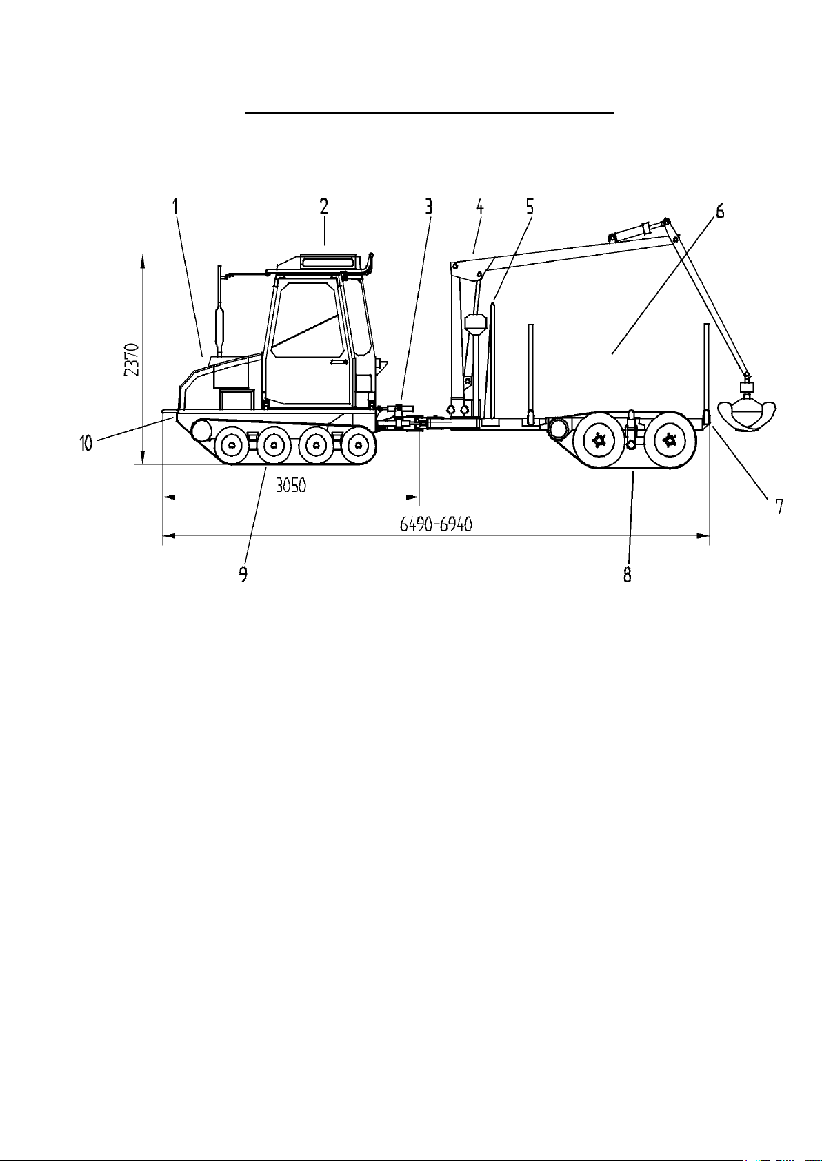
Main components of Terri 2040
1 Drive unit
2 Cab
3 Pulling bar with support cylinder
4 Grab-loader
5 Load shifting protection
6 Load area
7 Trailer
8 Track-bogie system
9 Track-bogie system
10 Winch
7
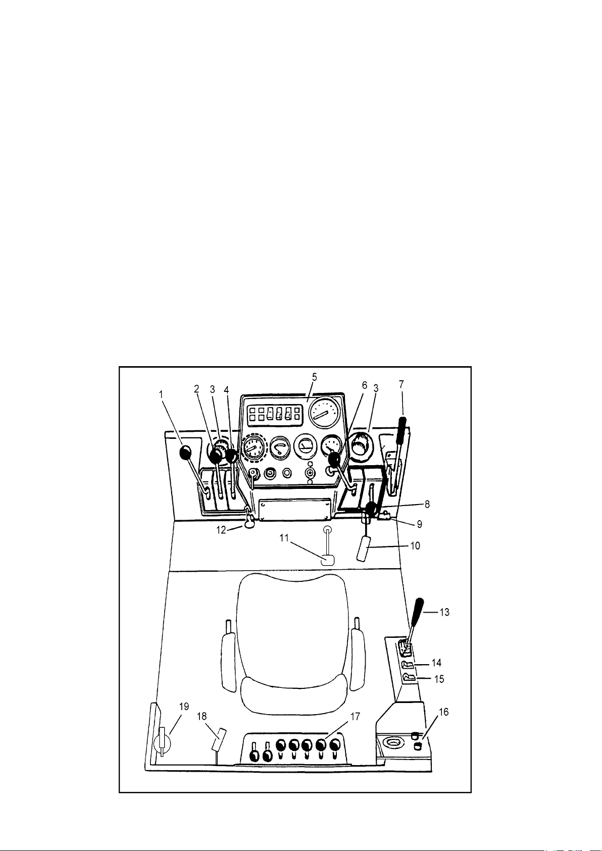
Instrumentation and controls
1 Load cylinder control lever
2 Differential lock (not Sweden)
3 Air vents
4 Winch lock control lever
5 Front dashboard
6 Winch control lever
7 Parking brake
8 Gear shift lever
9 Main switch
10 Accelerator pedal, front
11 Brake (only Sweden)
12 Hand throttle (optional equipment)
13 Drive lever
14 Switch with indicator for trailer drive
15 Switch with indicator for trailer parking brake
16 Rear dashboard
17 Grab-loader controls
18 Accelerator pedal, rear
19 Fire extinguisher
8
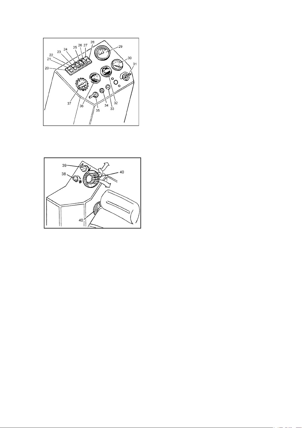
5 Front dashboard
20 Warning light for low hydraulic oil level
21 Warning light for differential lock engaged
22 Indicator for main beams
23 Glow plug indicator
24 Switch with indicator for main-dipped beams
25 Switch with indicator for working lights, side
26 Switch with indicator for working lights, rear
27 Warning light for low oil pressure in diesel engine
28 Charging indicator
29 Tachometer
30 Engine temperature gauge
31 Ignition switch
32 Hydraulic oil temperature gauge
33 Pushbutton for windscreen washer
34 Pushbutton for horn
35 Direction indicator
36 Fuel gauge
37 Running-time meter
16 Rear dashboard
38 Ventilation blower control
39 Cab heating control
40 Air vents
9
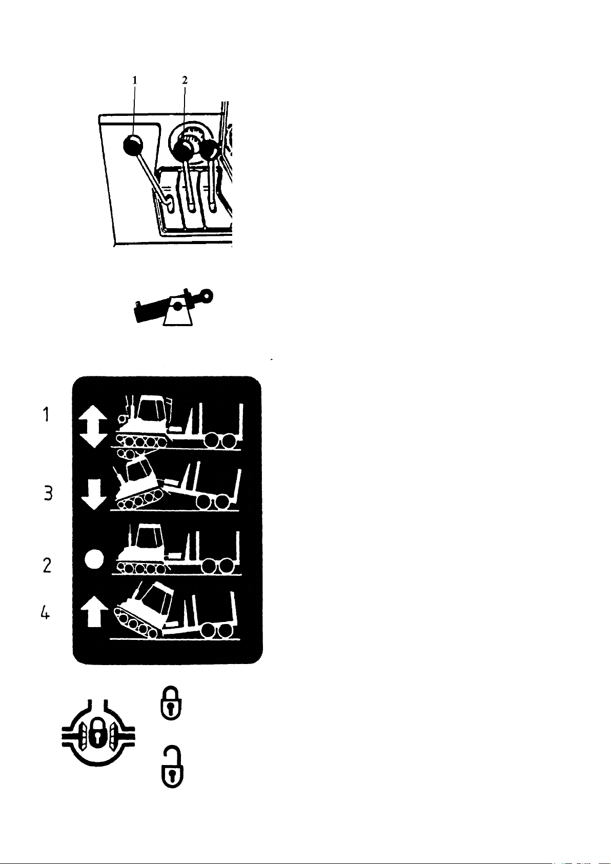
1 Load cylinder
With the help of the load cylinder, which is located
between the tractor and the trailer, it is possible to
adjust the position of the front of the tractor depending on different situations. The load cylinder
is operated with a lever to the left on the dashboard.
Position 1: The lever pushed upwards = the tractor
‘moves freely’, i.e., the tractor can freely follow
the terrain. It is recommended that this position
should always be used.
N.B. Spring-loaded locking of the lever in this position!
Position 2: The lever in the mid-position, with
spring loading in the centred position = ‘locked
position’. The position of the tractor in relation to
the trailer is locked. It is recommended that this
position should only be used during driving in
loose snow without any track or when the tractor
is driven over a ditch or the like.
Locked
Position 3: When the lever is moved forwards, the
front of the tractor is lowered. The lever returns
with spring loading to the ‘locked position’ (2),
when it is released.
CAUTION! Do not turn sharply when the front of
the machine is lowered.
Position 4: When the lever is moved downwards,
the front of the tractor is raised. The lever returns
with spring loading to the ‘locked position’ (2),
when it is released.
Practical example: Driving over a ditch of normal
size:
•Raise the front slightly when approaching the ditch.
•Lower the front before the tractor’s bogie has com-
pletely crossed the ditch so that the front of the bogie
touches the ground on the other side of the ditch.
•Drive the vehicle with the load cylinder in the
locked position until the trailer wheels have
crossed the ditch.
•Continue to drive the vehicle with the load cylinder in the ‘free position’.
Free
2 Differential lock
The tractor’s gearbox is provided with a mechanical differential lock, which is controlled with a
lever on the dashboard. When the lever is in its
lowest position, the differential lock is disengaged.
10

Locked
Free
3 Front air vents
The direction of the incoming air is controlled
with the air vents. The air is directed towards the
front windscreen to provide a defroster action.
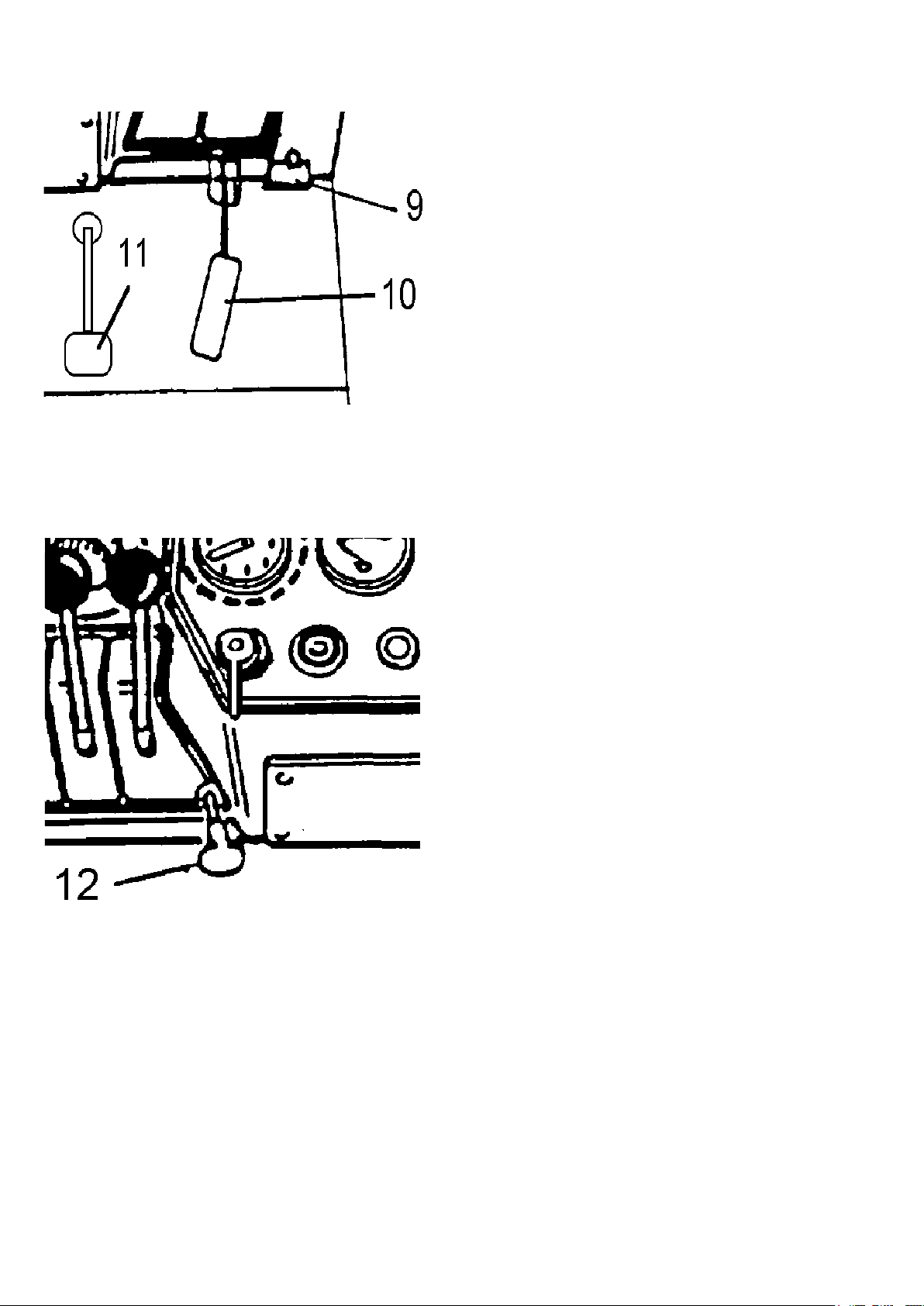
4 Winch lock
The winch lock prevents the wire rope from running out. It is operated with a lever to the left on
the dashboard. The winch lock is released when
the lever is in its upper position. Release the
winch lock and draw out the wire rope.
N.B. Wear protective gloves!
N.B. Never drive backwards with the drive lever
while using the winch! This may damage the gearbox.
Engaged
Disengaged
6 Winch
The winch is operated with a lever to the right
on the dashboard. When the lever is in the upper position, the gear in neutral, the trailer drive
disengaged, the drive lever forwards and the accelerator pedal is pushed, the wire rope is wound
up on the drum
N.B. Never drive backwards with the drive lever
while using the winch! This will cause the wire
rope to be wound up in the wrong direction on the
winch drum.
7 Parking brake
This lever actuates a mechanical brake yoke.
When the lever is moved backwards, the machine
is braked. The lock is released with the button at
the end of the lever.
High gear
Low gear
Gear shift lever
8
Two gears can be selected with the lever. If the
lever is moved upwards, the low gear is engaged,
while if the lever is moved downwards, the high
gear is engaged. When the lever stands in the
middle, the gearbox is in neutral.
11
9 Main switch
All the power supply is disconnected with the
main switch.
N.B. Never open the main switch when the engine
is running!
10 Accelerator pedal, front
The engine speed is controlled with the accelerator
pedal during driving.
11 Brake pedal
The machine is braked with the brake pedal.
12 Hand throttle
(optional equipment)
The engine speed can be set with the hand throttle.
Rough setting: press the button and withdraw it.
Fine setting: turn the knob.
12
 Loading...