

TerraWave T35170P1000690 Quick Start Manual
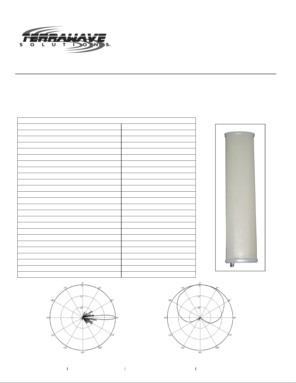
TerraWave Solutions® 3.5 GHz 17 dBi Sector Panel Antenna
with 90-Degree Horizontal Beamwidth and N-Style Jack Connector
TerraWave’s 3300-3800 MHz 17 dBi 90-degree sector panel antenna is designed for outdoor WiMAX network
applications. This antenna features high gain in a slim profile and is constructed of UV resistant PVC. The
antenna is easy to install and includes an articulating mast mount and integrated N-Style Jack connector. All
TerraWave antennas are covered by the Company’s two-year TerraNet warranty program. For questions and to
purchase product, contact a wireless networking solutions sales engineer at 210-375-8482, 800-851-4965 or
sales@terrawave.com. Visit www.terrawave.com for additional information.
Specifications
Model Number T35170P1000690
Frequency Range 3300 - 3800 MHz
Bandwidth 500 MHz
Gain 17 dBi
Polarization Vertical
Electrical Downtilt 0°
Half-power Beamwidth Horizontal: 90° / Vertical:6°
Front-to-Back Ratio ≥ 23 dB
VSWR ≤ 1.5
Impedance 50 Ω
Intermodular Distortion (2x43 dBm Carrier) ≤ -150 dBc
Maximum Input Power 100 Watts
Lightning Protection DC Grounded
Connector N-Style Jack (female)
Connector Position Bottom of Antenna
Dimensions 31.10" (H) x 4.49" (W) x 2.13" (D)
Antenna Weight with Installation Kit 5.73 lbs
Wind Loading Area 0.11 Ft²
Rated Wind Velocity 134.2 mph
Reflector Material Aluminum Alloy
Radome Material UV PVC
Radome Color Pantone Cool Gray
Mechanical Tilt 0-10°
Operating Temperature Range -40° F - +140° F
Mounting Hardware 1.18" x 2.76"
E-Plane H-Plane
www.terrawave.com Email: sales@terrawave.com Phone: 210-375-8482 or 800-851-4965 10521 Gulfdale, San Antonio, TX 78216

TerraWave Solutions® 3.5 GHz 17 dBi Sector Panel Antenna
with 90-Degree Horizontal Beamwidth and N-Style Jack Connector
Installation Information for T35170P1000690
I. Tools Required: Two 13 mm Box Wrench
II. Installation Diagram:
Strap Arm
Tune Up Angle of Antenna
Clamp
Bolt M8
Top Mounting Assembly
Pole
Antenna
Bottom Mounting Assembly
III. Installation Instructions:
A. Loosen the nuts on the Strap Arm.
B. Remove the bolts, M8 nuts, 8 lock washers and flat washers from the mounting clamps. Wrap the clamp
around the pole and then reassemble the M8 bolts, the 8 flat washers, 8 lock washers and the M8 nuts.
Adjust the position of the clamp and then tighten it with the M8 nuts.
C. Repeat step B above and attach the other clamp of the bottom mounting assembly on the pole.
D. Adjust the antenna until it is perfectly vertical (slightly loosen the clamp of the top mounting assembly to
readjust its position if necessary). Set the desired antenna tilt angle and then tighten all nuts in the top
and bottom assembly.
E. Remove the protective caps from the antenna connectors. Connect and tighten the cable connectors and
thoroughly wrap the cable connectors with weatherproofing.
F. The antenna is normally mounted vertically or tilted downward by adjusting the mounting assemblies.
However, the top and bottom mounting assemblies could be switched to be mounted for upward tilting.
Notes:
- Ensure the antenna is installed in a safe and suitable location and well away from high power lines.
- Do not attempt to install during inclement weather.
- Do not attempt to install the antenna on a pole with a diameter other than 1”-3”.
www.terrawave.com Email: sales@terrawave.com Phone: 210-375-8482 or 800-851-4965 10521 Gulfdale, San Antonio, TX 78216
 Loading...