

Page 1
wireless infrastructure
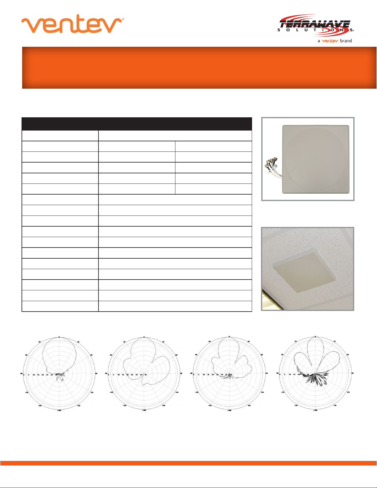
TerraWave High-Density 2.4/5 GHz 10/11 dBi Ceiling-Mount Antenna
With N-Style Jack Connector
SPECIFICATIONS
Specications- SKU# 567653
Model M6100110MP1D41802
Frequency Range 2400-2500 MHz 5150-5850 MHz
Bandwidth 100 MHz 700 MHz
Gain 10 dBi 11 dBi
Vertical Beamwidth
Horizontal Beamwidth
VSWR ≤1.8
Front to Back Ratio ≥25 dB
Isolation ≥30 dB
Nominal Impedance 50 Ohm
Polarization Vertical/Horizontal
Maximum Power 20 W
Wind Rating 123 mph
Connector Type N-Style Jack
Dimension 10.3”x 10.3”x 1.4”
Weight 4.4 lbs.
Mast Diameter 1.57” - 1.97”
28
40
°
°
18
24
°
°
2.4 GHz: H-Plane
© 2013 Ventev
2.4 GHz: E-Plane
www.ventev.com sales@terra-wave.com 800-851-4965
5 GHz: H-Plane
5 GHz: E-Plane
Page 2
wireless infrastructure
TerraWave High-Density 2.4/5 GHz 10/11 dBi Ceiling-Mount Antenna
With N-Style Jack Connector
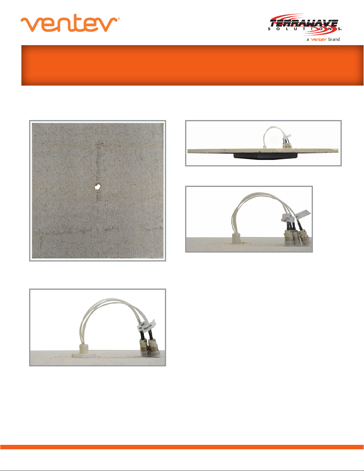
MOUNTING INSTRUCTIONS
Figure 2
Figure 1
Figure 3
Figure 2a (Close-Up)
1. Drill 1” hole in ceiling tile (See Figure 1).
2. Pull leads through drilled hole and
ensure antenna is ush against ceiling
tile (See Figure 2).
3. Tighten screw mount until antenna is
securely fastened (See Figure 3).
4. Insert ceiling tile into grid.
© 2013 Ventev
www.ventev.com sales@terra-wave.com 800-851-4965
 Loading...