

Page 1
2.4/5 GHz 3 dBi Above Ceiling Omni Antenna
With RPTNC Plug Connectors
TerraWave’s dual band 2.4/5 GHz above ceiling mount multiple-input and multiple-output (MIMO) omnidirectional antenna is
designed to operate with the Cisco 1252 Access Point (AP). The antenna features three integrated 2.4 GHz 3 dBi antennas and three
integrated 5 GHz 3 dBi omni antennas in one enclosure. It consists of a high-performance circuit design, Flame Retardant 4 (FR-4)
rated material and six plenum-rated 24” UL94-V0 pigtails, making it an excellent re-resistant above ceiling tile mounted antenna.
The antenna is specically intended to support demanding applications in next generation IEEE 802.11n wireless communication
systems where aesthetics matter. Includes above ceiling tile mounting bar. Every TerraWave antenna is covered by the Company’s
two-year TerraNet warranty program. For questions and to purchase product, contact a Regional Sales Executive at 210-375-8482,
800-851-4965 or sales@terrawave.com.
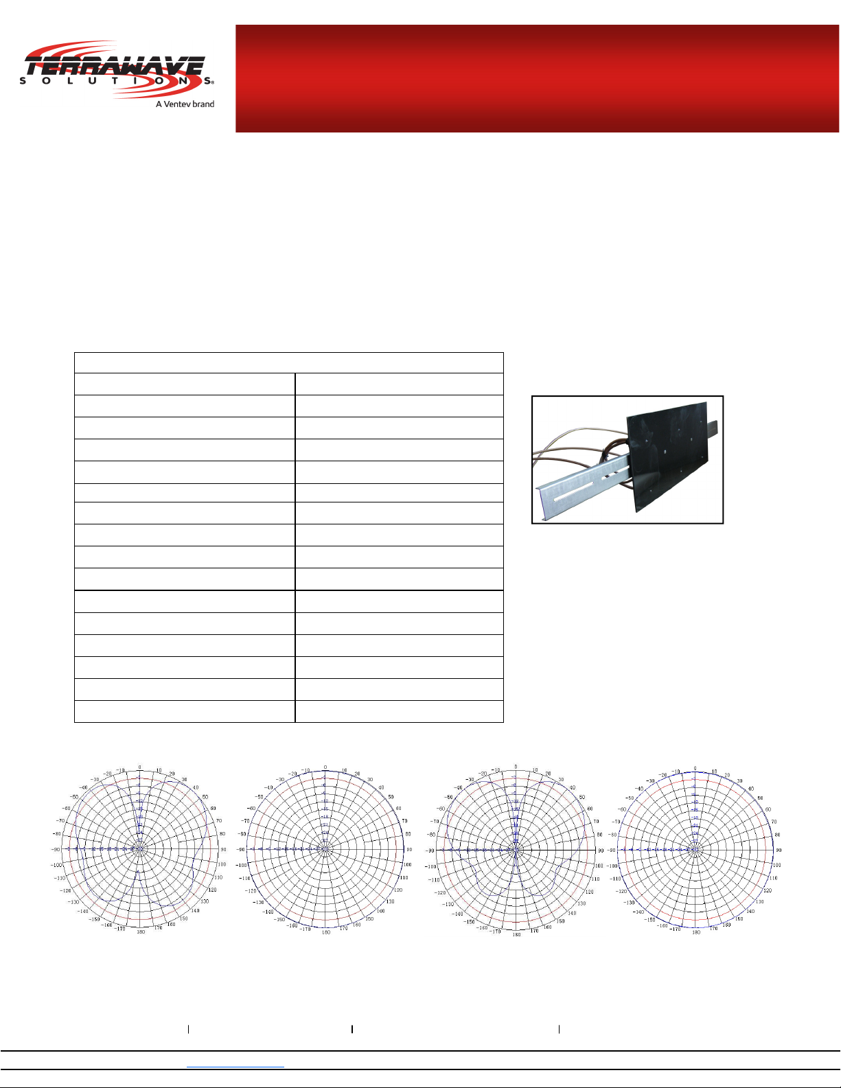
Specications
Model M6030030O32402A
Frequency Range 2400~2500 / 5150~5850 MHz
Bandwidth 100 / 700 MHz
Gain 3 dBi
Vertical Beamwidth 60° / 50°
Horizontal Beamwidth 360°
VSWR ≤ 2.0
Nominal Impedance 50 Ohms
Polarization Vertical
Max Power 50 Watts
Connector RPTNC Plug
Dimensions 13.8” x 6.3” x 1.2”
Weight 2.64 lbs
Operating Temperature Range -22°F to +158°F
Mounting Style Above Ceiling Mount
Mounting Bar Dimensions 24” x 1.6” x 0.3”
Key Feature:
TerraWave’s 802.11n 2.4/5 GHz 3 dBi
Above Ceiling Mount Omnidirectional
Antenna is made with:
Flame Retardant-4 (FR-4) Rated
Material
Six Plenum-Rated UL94-V0 24”
Pigtails
E-Plane Pattern H-Plane Pattern
2.4 GHz
www.terrawave.com Email: sales@terrawave.com Phone: 210-375-8482 or 800-851-4965 10521 Gulfdale, San Antonio, TX 78216
www.terra-wave.com sales@terra-wave.com 1-800-851-4965
E-Plane Pattern H-Plane Pattern
5 GHz
Page 2
2.4/5 GHz 3 dBi Above Ceiling Omni Antenna
With RPTNC Plug Connectors
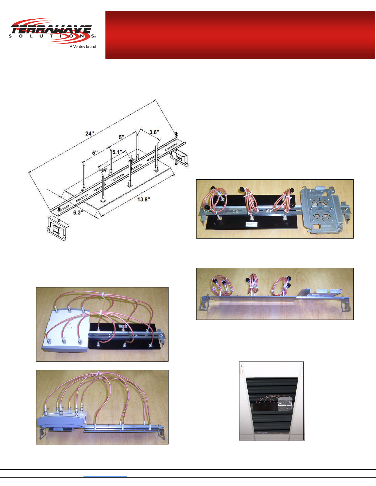
Mounting Bracket Information
TerraWave’s Above Ceiling Tile Mounting Bracket is speci-
cally designed to support and mount the above ceiling tile
antenna or, optionally, the above ceiling tile antenna and
the AP the antenna operates with.
Installation Instructions
Step 1
Install the above ceiling tile antenna and the AP mounting bracket
to the antenna bracket with the supplied wing nuts and screws.
Step 2
Install the AP to the secured AP mounting bracket. Screw on the
antenna’s pigtails and connectors to the AP.
Example 2A—Top View
Example 1A—Top View
Example 1B—Side View
Step 3
Remove the ceiling tile and install the complete solution to the
ceiling tile grid using the antenna mount’s side clips. Once installed, replace the ceiling tile.
Example 2B—Side View
www.terra-wave.com sales@terra-wave.com 1-800-851-4965
Example 3—Complete Solution Installed Above the Ceiling
 Loading...