

Page 1

Installation Procedures and Users Guide
Page 2

2
Contents
..................................................................................................................................................................1
..................................................................................................................................................................1
............................................................................................................................1
GTRM 100 Installation Guide ........................................................................................................................ 4
Overview ...................................................................................................................................................4
GTRM Standard Components ................................................................................................................... 4
GTRM Optional Accessories ......................................................................................................................4
GTRM 100 Overview .................................................................................................................................5
GTRM Installation ......................................................................................................................................... 6
Installation Steps...........................................................................................................................................7
Step 1: Mounting the GTRM .....................................................................................................................7
Step 2: Choose the Connection points to monitor and then Run the Wiring. .......................................... 7
Step 3: Connect Power to the GTRM ........................................................................................................8
Step 4: Make Final Connections To GTRM ................................................................................................ 9
Step 5: GTRM Power up and Final Installation Testing ............................................................................. 9
GTRM Configuration ...............................................................................................................................10
The Toroid Ground Sensor ..................................................................................................................11
To Install the Toroid Ground Sensor ...................................................................................................11
Connecting the GTRM Channel Terminals ..........................................................................................11
Activating GTRM Channel Monitoring ................................................................................................11
Using the Web Interface to Configure the GTRM ...................................................................................12
For Direct GTRM to PC Connection.....................................................................................................13
GTRM Web Interface Menus ..................................................................................................................16
System Status..........................................................................................................................................16
Channel Setup .........................................................................................................................................17
Options....................................................................................................................................................18
Email Configuration ................................................................................................................................19
Email Test................................................................................................................................................20
Network Configuration ...........................................................................................................................21
SNMP Configuration ...............................................................................................................................22
Help .........................................................................................................................................................23
Page 3

About and Factory...................................................................................................................................24
SNMP Functionality.................................................................................................................................26
Network SNMP Monitoring.................................................................................................................26
SNMP Monitoring through a MIB Browser .........................................................................................26
To Install MIB Browser ........................................................................................................................26
Install SNMP Traps File........................................................................................................................26
Configure the Trap Receiver ...................................................................................................................29
Cannot bind to port 162 Error Message .................................................................................................30
Open Trap Receiver.................................................................................................................................33
3
Page 4

GTRM 100 Installation Guide
Overview
The GTRM 100 was designed to provide an easy and convenient way to remotely monitor ground
cabling and components at site locations prone to copper theft.
The GTRM 100 contains everything you need to activate alarms and automatically send alert messages
via email or SNMP. Providing you with instant feedback the moment a copper line is cut or a ground bar
has been removed that is being monitored by one of the 5 ground monitoring channels on the GTRM.
The procedures in this guide outline the steps you should follow to correctly install and operate the
GTRM 100.
**DANGER**Although the GTRM 100 Monitors grounding components caution should be taken during
installation. Live power wires may be in close proximity to the installation location of ground monitor
leads or the main unit. Do Not touch or remove any live AC lines during the installation of the GTRM.
Serious Injury or Death could occur from electrocution.
GTRM Standard Components
The GTRM is a self-contained DC powered unit an optional AC power adapter is available if your
installation requires it. Please verify that you have received everything with your order.
(1) GTRM unit
(1) AC Power Adapter (Optional)
(1) Toroid Ground Sensor (Optional)
(1) 3’ Ethernet Cable
(1) User’s Guide
GTRM Optional Accessories
For additional ground monitoring you can purchase a clip-on toroid sensor to provide additional
monitoring of ground quality at the site. This accessory plugs into the RJ11 port on the GTRM and clips
over any site ground cable you wish to monitor. The sensor is then activated from the web browser
configuration interface.
Toroid Clip-on Ground Sensor
AC Adapter
4
Page 5

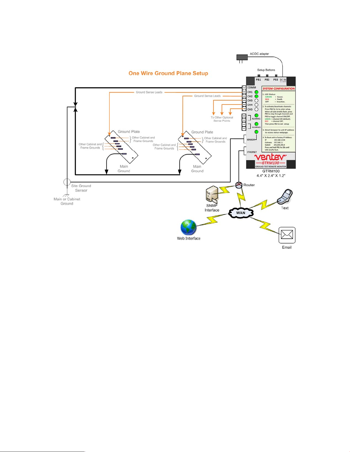
GTRM 100 Overview
Use the Diagram below to familiarize yourself with the GTRM components and features.
5
Page 6
GTRM Installation
Because the GTRM can be used in a variety of applications there are many variations on exactly how the
GTRM can be installed and connected to ground lines. Please use the steps below as a guideline for
installing the GTRM. Proper testing should be done after installation to ensure you receive the desired
level of alarming and alert messages.
6
Page 7
7
Installation Steps
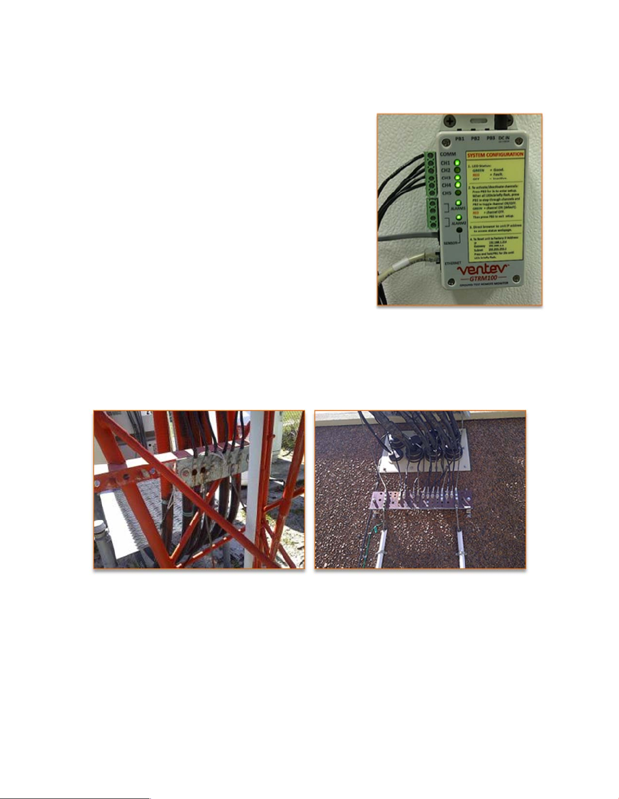
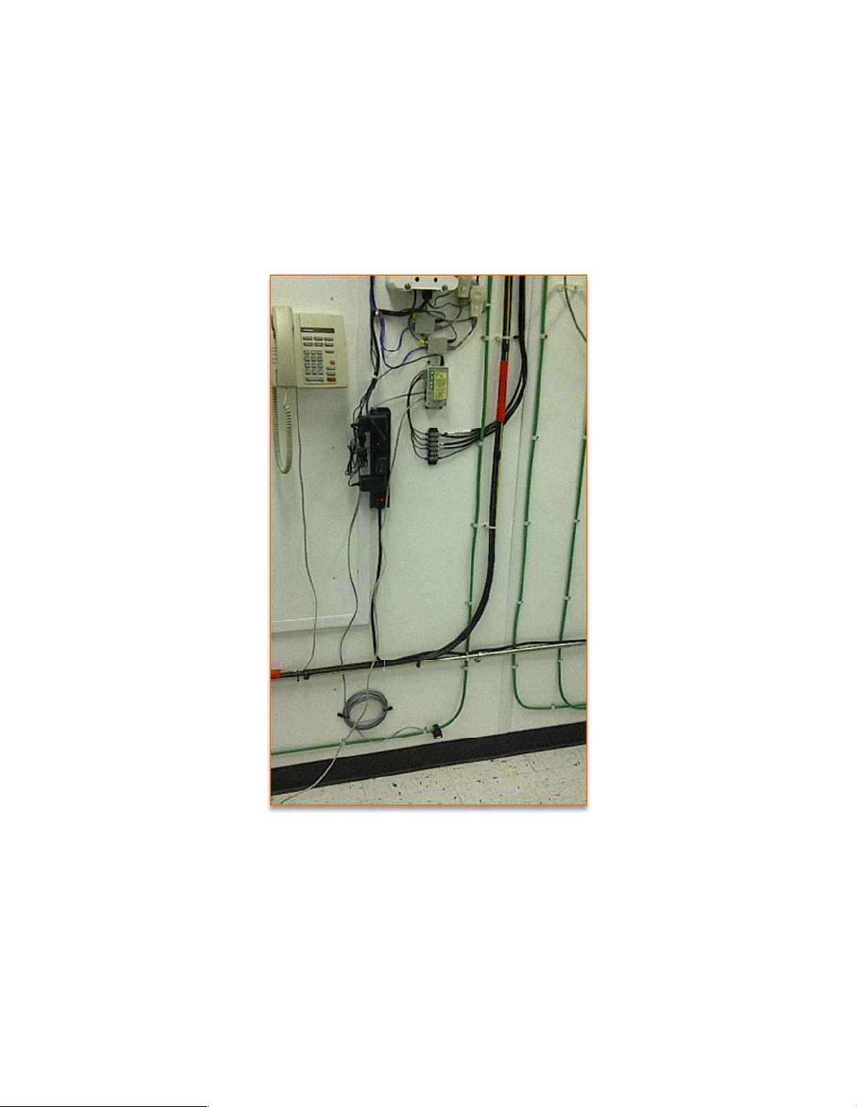
Step 1: Mounting the GTRM
Mount the GTRM in a suitable location inside the shelter or
cabinet.
The GTRM mounts easily to any flat surface. The mounting
flanges can be used to mount to wall or board, two-sided tape
or Velcro can also be used to secure the GTRM.
The mounting location should be in close proximity to the exit
point of the ground wires that you wish to monitor.
Step 2: Choose the Connection points to monitor and then Run the Wiring.
Typical locations to monitor are the main shelter ground bar and the tower ground bars. Leads should
be run from each channel terminal on the GTRM to each point you wish to monitor.
Connecting the Channel Monitor Wires: Connections to the tower ground bars and the shelter ground
bars typically use #6 wires. You can connect to these locations with smaller gauge wiring but it is
common practice to use the #6 wiring and lugs to connect the GTRM to these monitor points in order to
“mask” or “hide” the installation and make all the connection look the same.
Page 8
8
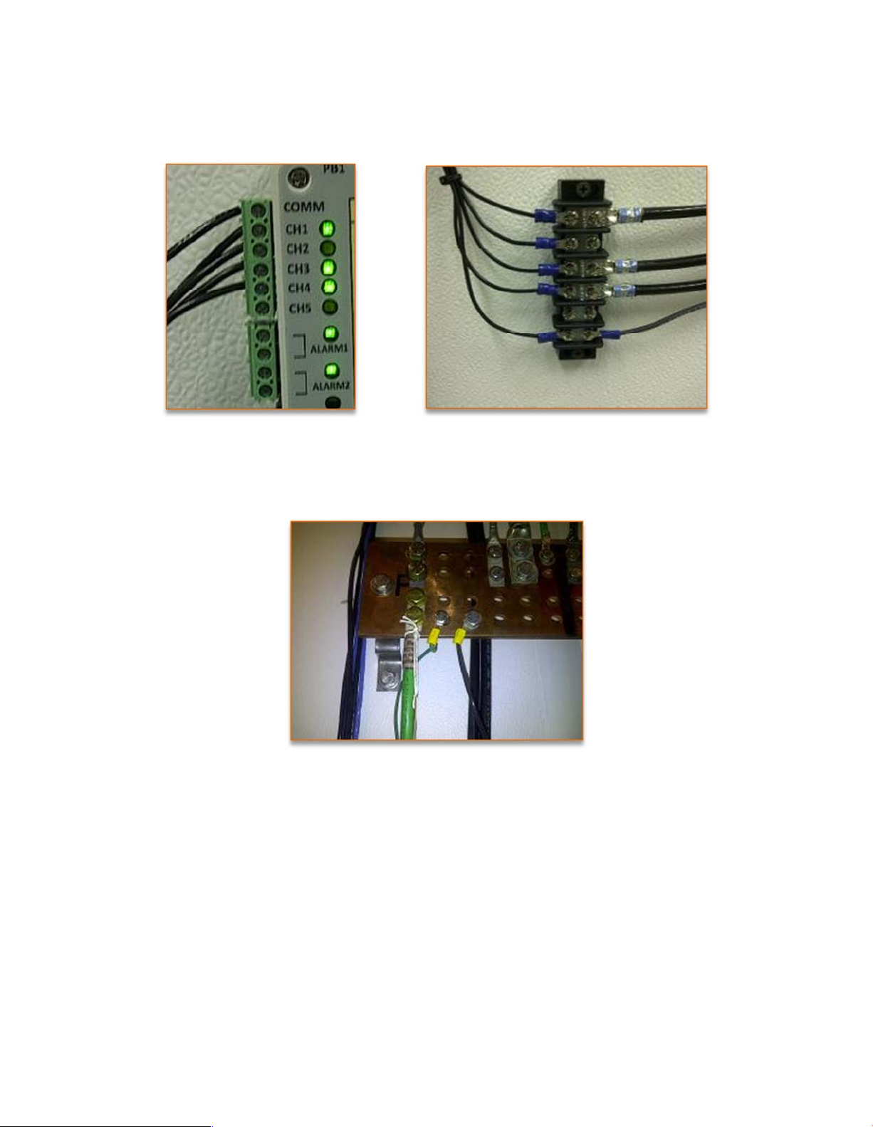
Using a Terminal Block: The #6 wiring will then be reduced to 18 AWG wire inside the cabinet or shelter
by using a standard terminal block. The 18AWG will then connect to the GTRM channel block.
Connecting the Comm Terminal: The Common wire from the GTRM is connected to the main ground
bar inside the shelter or cabinet. The common wire must be connected or the GTRM will not function
properly.
Step 3: Connect Power to the GTRM
The GTRM comes in both AC and DC versions. The DC version is preferred as it allows you to connect the
GTRM directly to your site power supply which takes advantage of battery backup and provides
continuous monitoring in the event of a power outage or if the copper thieves cut the AC power to the
site.
DC powered GTRM will wire directly into your site DC power supply or terminal block.
AC powered GTRM comes with an adapter that plugs into any standard 120VAC outlet or power strip.
Page 9
9
Step 4: Make Final Connections To GTRM
Choose your method of alarming and make Ethernet and Dry Contact connections as necessary.
Ethernet Connection will require you to configure IP Network Settings and Email parameters.
SNMP trap messages and network configurations will be necessary if using GTRM SNMP functionality for
alarming. Coordination with your network administrator will be necessary to configure SNMP alarming
on the GTRM.
Dry Contacts can be set to normally Open or normally Closed and can be access via the browser
interface.
Step 5: GTRM Power up and Final Installation Testing
Once the GTRM is powered verify functionality and alarm notifications. If using the Web Browser to
configure the GTRM, it may be necessary to power cycle the GTRM in order for it to update save the
changes.
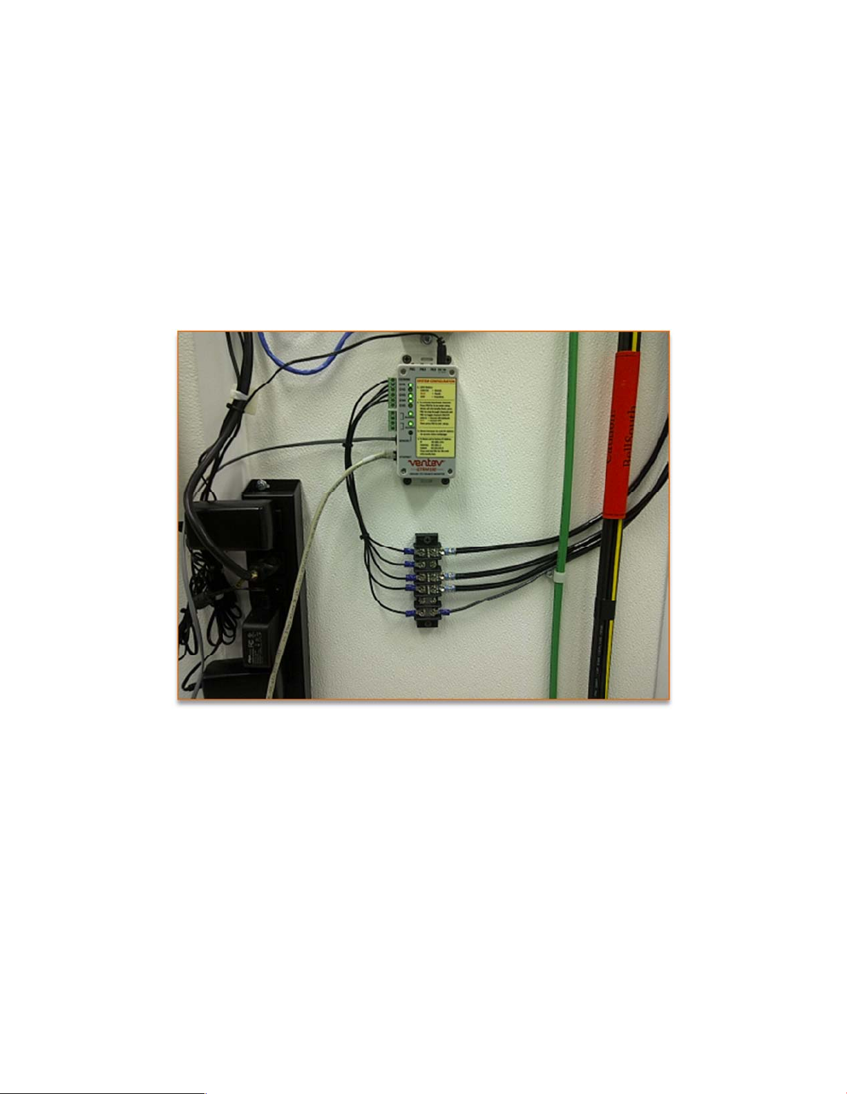
The terminal block (if installed) can be used to simulate copper cuts and test your installation to verify
that the GTRM goes into alarm and that everything is configured properly.
By removing connections at the terminal block you should see the GTRM go into alarm and you can
verify:
Page 10
10
If using email alerts, confirm receipt of alarm notification email when GTRM goes into alarm. This will
verify your network and email configurations are correct.
Verify SNMP setup and receipt of correct SNMP messages when GTRM goes into Alarm
Confirm dry contact configuration and wiring is setup correctly when GTRM goes into alarm. If using the
dry contacts to wire into an existing alarm monitoring system, verify that the alarm company is seeing
the alarm notification.
GTRM Configuration
The GTRM monitors and senses Ground wires in two different manners. The first is through a ground
sensor Toroid to detect the presence of an active ground and the second uses pulse monitoring through
up to five different channels to detect connectivity of ground lines to a ground plate.
Page 11

The Toroid Ground Sensor
The Ground sensor uses a clip-on toroid to detect low level currents on the ground wire that generate a
magnetic field inside the toroid. The Toroid converts this magnetic field to electrical current and passes
it on to the GTRM. If the magnetic field is no longer present, (ground is lost), the current to the GTRM i s
interrupted causing the GTRM to go into alarm.
When the Toroid Sensor is in alarm, the indication will be displayed through
Alarm 2 on the GTRM.
To Install the Toroid Ground Sensor
1. Locate the main ground feed wire that you wish to monitor.
2. Open the clip sensor and place the sensor around the wire.
3. Close the clip sensor around the ground wire.
4. Connect the Ground Sensor wire to the RJ11 jack on the GTRM
5. Enable the Sensor by checking the appropriate box in the Options
Menu of the Web interface.
Connecting the GTRM Channel Terminals
The GTRM can monitor up to 5 different channel lead locations. The channel terminal blocks will accept
18 – 24 AWG wire. It is recommended that you use smaller wire to connect directly to the GTRM
channel terminal blocks and then use a split-bolt style connector to attach the channel wire lead to a
larger wire that will then connect to your ground plate.
1. Using 16 or 18 AWG wire, determine the correct length needed to connect to copper ground
wire or to attach directly to the ground plate.
2. Strip off approx. ¼” of coating to expose copper wire and insert into channel terminal. Screw
down terminal to secure wire. Repeat for the desired number of channels you wish to monitor.
Note: you do not need to wire all terminals. You can use any of the terminals or all of the terminals.
You can activate and deactivate each channel by using the push buttons on top of the GTRM or by
accessing the configuration settings through a web browser.
Activating GTRM Channel Monitoring
The GTRM monitors up to 5 separate channels. Each channel operates independently and can be
activated or deactivated by either the push buttons on top of the unit or through the configuration
menu.
11
Page 12
Push Button Configuration: To activate or
deactivate channels
1. Press PB3 for 3 seconds to enter setup
mode.
2. When All LEDs briefly flash, press PB1 to
step through channels
3. Press PB2 to toggle channel on/off
a. GREEN LED = channel ON
b. RED LED = channel OFF
4. Press PB3 to exit setup and save
configuration
For Factory Reset
1. Hold PB1 down for 15 to 20 seconds until all LEDs blink, then release button.
Webpage Configuration – Use your web browser to connect to the GTRM. Default IP address is:
192.168.1.214.
Type this address into your web browser with the GTRM connected to the network or directly to
your laptop via an Ethernet cable.
Channels can be toggle on and off through the pulldown selection for each channel.
Click Save button before exiting menu.
Using the Web Interface to
Configure the GTRM
1. Before connecting to the GTRM’s web
interface, supply power to the unit.
2. Connect Ethernet Cable
a. Use an Ethernet cable to connect
the RJ45 port on the GTRM to the
network or you may also connect
directly to your PC’s Ethernet port.
12
Page 13

3. Verify Your Network settings and Connection to the GTRM – You can ping the GTRM to verify
connectivity.
For Direct GTRM to PC Connection
For the initial configuration of the GTRM and to change Network setting IP settings for placement in an
IP based network you will need to connect the GTRM directly to your PC. Once connected to your PC
you will be able to configure the GTRM to match your network settings.
You will need the following information from your network administrator to add the GTRM to your IP
Network:
IP Address – we recommend using a static IP address for the GTRM
Gateway – what is the IP address of the Gateway of your network
Subnet Mask – what is the mask of your network
Primary DNS – IP address of the primary DNS server for your network
Once you have your connection made to you laptop or PC you will need to record your IP address and
verify connection to the GTRM.
NOTE: It may be necessary to give your PC or Laptop a static address to access the GTRM default
network.
Example: IP Address: 192.168.1.200
Subnet mask: 255.255.255.0
Use the following screen shots to guide you into finding your IP address and record your address for use
later.
1. Click Start and then Run
13
Page 14

2. In the window type cmd and click OK
3. Type ipconfig then <Enter>
4. Record your IP Address
14
Page 15

5. Verify connectivity to the GTRM by sending a Ping command to the GTRM’s default IP address:
PING 192.168.1.214 <Enter> you should receive four REPLY messages from the GTRM.
6. Open a New Web Browser Session (Internet Explorer, Firefox or Google Chrome) and type in the
address of the GTRM (default is 192.168.1.214) and click go or <enter>. If everything is set up
15
Page 16

correctly you should see the System Status of the GTRM. Note: The Status light blinks when the
GTRM is active.
GTRM Web Interface Menus
The GTRM will need to be configured to match your network settings as well as your email and SNMP
notification if those features are to be used.
The following Screenshots will explain the different menus of the GTRM user interface. This interface
allows you to remotely configure and change settings across the network.
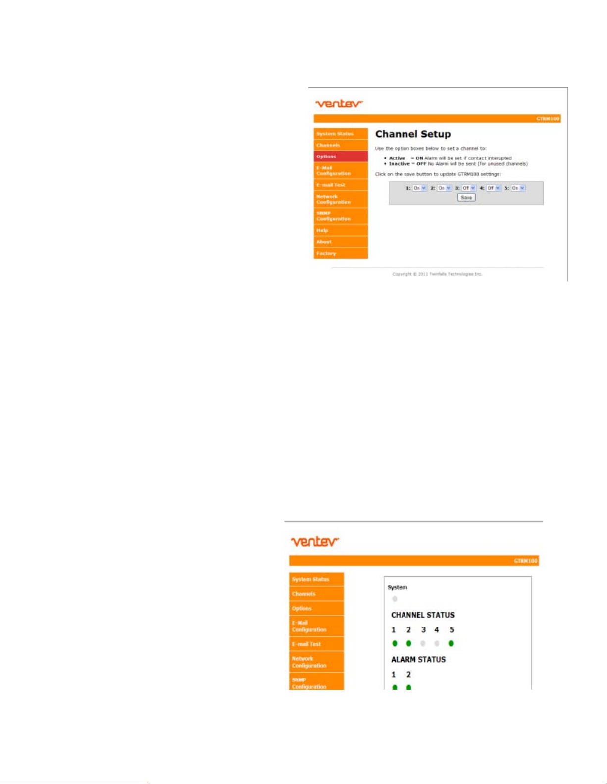
System Status
16
Page 17

This screen displays an overview of the channel status on the GTRM. You can quickly see any alarms
occur by watching this screen. You can show the alarms on this screen by removing any one of the three
ground leads to cause an alert on the GTRM.
Channel Setup
Channel Setup
17
Page 18

This screen walks your through the channel setup. You can turn on or off any of the channels at
anytime. If you only want to monitor two or three channels then turn those channels on while the
others remain off.
Options
18
Page 19

The options screen provide you access to the Alarm contacts. You can toggle between normally open or
normally closed contacts.
You can set the Alarm contacts up independently of each other enabling you many possiblities for
external alarm notifications.
UPDATE: The Options screw now contains a check box to enable the Ground Sensor.
Email Configuration
19
Page 20

The email configuration screen is where you setup the contact information of the person you want to
alert when the GTRM goes into alarm.
Contact: Enter the name of the contact person responsible for the site.
Location: Enter a short description of the site location the GTRM is monitoring
The following information should be obtained from your Network Administrator to setup the SMTP
server.
Port: Enter the Port number the SMTP server uses, select SSL if it uses Secure Socket Layer
Username: username for the SMTP server account
Password: Enter the password for the account
Server Address: enter the SMTP server address (example: smtp.gmail.com)
Email address: Enter the email address of the person you want the email alert to be sent to.
Email Test
20
Page 21

When you have everything set up correctly, use the Email Test screen to send a test email to your
account. This will verify the settings.
Note: You must have a direct connection to the Internet in order for the email alerts to work. If you are
connected to a corporate network or behind a firewall the email alert may not work. A network
administrator will need to configure the GTRM to be part of the network and give it access to the
Internet to ensure the email configuration works properly.
If everything is setup correctly, click “Send Test Message” and in a few seconds you should receive an
email from the GTRM. If it works, you are setup properly and you will now receive alert messages
anytime the GTRM goes into alarm.
Network Configuration
21
Page 22

This screen allows you to configure the Network settings on the GTRM. DO NOT change any of the
settings here unless you know what you are doing. These settings should be configured under the
direction of your network administrator.
Multiple GTRM’s could be active in the network at the same time. Each will have its own IP address to
allow for remote access and monitoring.
To access any GTRM in the network, open a web browser and type the IP address of the GTRM into the
address bar. Each GTRM should have their own unique address when they are part of the same
network.
SNMP Configuration
22
Page 23

This screen provides access to the SNMP settings. If you wish to use SNMP alerts the Read and Write
strings will need to be configured to match your network. These settings should only be changed by a
Network Administrator or by someone who understands the proper settings for your network.
NOTE: SNMP configurations may be confusing. Please consult your Network Administrator to assist
you in the SNMP configuration and setup.
Help
23
Page 24

The Help screen provides you with the Default settings for the GTRM and instructions on how to
configure the major options on the GTRM. It explains in detail how to manually configure the GTRM
using the configuration buttons on the top of the unit.
About and Factory
24
Page 25

The About and Factory Screens provide you with software version information and provide access to
restore the GTRM to factory defaults.
25
Page 26

SNMP Functionality
In order to accept SNMP messages being sent from the GTRM you will need to have an SNMP
monitoring system in your network or a MIB browser loaded onto your laptop.
Network SNMP Monitoring
For Network SNMP functionality, consult your network administrator for SNMP setu p and configuration
parameters and how the GTRM should be configured for your specific SNMP requirements and trap
receivers.
A MIB browser can be used to capture SNMP traps in place of a network SNMP trap receiver The MIB
Browser can be loaded onto a PC or Laptop for monitoring of GTRM SNMP Traps. The MIB browser will
need to be on the same network as the GTRM in order to receive the messages.
SNMP Monitoring through a MIB Browser
A MIB Browser will allow you to accept SNMP messages on any PC or Laptop. A suitable MIB Brower can
be downloaded (FREE Version) from http://www.ireasoning.com
IMPORTANT: Once the MIB Browser is loaded you will need to load the GTRM MIB file. If you did not
receive this file with your GTRM please contact Ventev innovations or your TESSCO Account Manager to
download the file.
To Install MIB Browser
1. Download MIB Browser from http://www.ireasoning.com
2. Open MIB Browser Folder
3. Click on the Setup.exe file
4. Click Run and Follow the installation instructions
5. Click Close when the installation has completed
6. Launch the MIB Browser
Install SNMP Traps File
1. In the MIB Browser – Click on the File Tab
2. Select Load MIBs
3. In the Open Window, locate the file called tft_2.mib (This traps file should be located in the
software files included with your GTRM)
4. Click on the tft_2.mib file
5. Click Open
26
Page 27

Once the MIB browser is loaded, click on the desktop icon to launch it. You will see the main screen
that should look similar to the one below. In the Address field type in the IP address of the GTRM.
192.168.1.214 also, expand the folders on the left menu and highlight private.
From the Operations pull down menu select “Walk” and click Go
27
Page 28

You should see data results begin to fill up in the main window Results Tab
28
Page 29

Configure the Trap Receiver
In order to receive SNMP Traps (alert messages) you will need to setup your MIB browser to receive
them. This means you need to setup your TrapReceiver so that the GTRM knows where to send the
traps. So in the next you will setup the TrapReceiver IP address. (You will set this to the IP address of
your laptop that you recorded earlier)
In the Results Table locate the line that says trapReceiverAddress.0 , right click on the line and select
“set”
29
Page 30

Enter the IP Address of your PC or Laptop in the Value field and click OK
Note: In order to receive SNMP messages the GTRM and the associated PC or Laptop must be on the
same network or be able to communicate across networks. Verify connectivity by pinging the GTRM
with your PC or laptop. If you receive a reply you should be able to receive SNMP messages.
If your entry was successful you will see a SET succeeded window.
Cannot bind to port 162 Error Message
Depending on your computer configuration you may get an error message pop up that says that you
cannot bind to port 162. SNMP uses port 162 and sometimes Windows has an active SNMP server
running that is using port 162. If you get this message you will need to follow the steps below to kill the
process using the port.
30
Page 31

Steps to shut down Application binding to Port 162
1. Load CurrPorts software – find the cports.exe file on the thumb drive and load it onto your
computer.
2. Click on the cports.exe icon to launch the software
3. When the software opens click Run
31
Page 32

4. Locate the application that is using port 162 by finding it under the Local Port column. Click on
the line to highlight it.
5. Right click on the highlighted line (ensure you are on the line of the process using port 162)
select “Kill Processes Of Selected Ports”
32
Page 33

6. Select Yes on the window that asks if you want to kill the process.
7. You should now be able to return to the MIB browser and continue to open the Trap
Receiver.
Open Trap Receiver
In order to see the SNMP alert messages coming in you will need to open the trap receiver Tab. To do
this, in the MIB Browser, go to Tools and select Trap Receiver.
33
Page 34

You should now see a Trap Receiver Tab in the main window of the MIB Browser.
Now, in order to see the SNMP traps coming in you need to throw the GTRM into an alarm by removing
one ground lead at a time.
As you remove the first ground lead you should see the GTRM alarm LEDs go red and the amber LED
light illuminate on the Demo kit. In a few seconds you should see an SNMP message alert come into the
trap receiver in the MIB Browser.
34
Page 35

When you remove a second ground lead you should see the second alarm on the GTRM, the RED LED
illuminate and you should receive the second SNMP message come into the MIB Browser.
ALSO NOTE: along with the LED alarms, the software alarms in the GTRM user interface and the SNMP
alert messages, the GTRM is also sending out email message alerts to the email address that you
configured in the email setup section.
35
Page 36

Sreenshot of the User Interface Status Screen showing alarm on Channel 2
Screenshot of SNMP Messages – If you click on the SNMP messages you can read the detailed
description including timesstamp and location the message was sent from.
36
Page 37

If you have any further questions or require assistance installing and configuring your GTRM
100 please contact your Account Manager or call TESSCO Technical Support.
1-800-472-7373
We Appreciate Your Business
37
 Loading...