

Page 1

VENTEV INNOVATIONS BTRM200 Battery Test Remote Monitoring System – User Guide V1.0
1
Innovations
BTRM200
Battery Test Remote Monitor
User Guide
Contact :
Ventev Innovations
10999 McCormick Road
Hunt Valley, MD 21031
Phone Number 800.759.9996
Email
Info@ventev.com
Page 2

VENTEV INNOVATIONS BTRM200 Battery Test Remote Monitoring System – User Guide V1.0
2
Contents
1. Warnings...............................................................................................................................4
2. Supplied Accessories ............................................................................................................4
3. Overview...............................................................................................................................4
4. System Description ...............................................................................................................5
4.1. Overall System Connection Diagram.............................................................................5
4.2. System Connector Overview .........................................................................................5
5. Basic setup ............................................................................................................................6
5.1. Connecting unit to a PC.................................................................................................6
5.2. Initial Power up to set IP address..................................................................................6
5.3. Accessing your host computer’s network settings .......................................................7
5.4. Setting IP address information for BTRM default .........................................................8
5.5. Verify IP address information........................................................................................8
6. Unit Deployment ................................................................................................................13
6.1. Mounting.....................................................................................................................13
6.2. Wiring Battery Connection..........................................................................................13
6.3. Wiring Power Supply Connections ..............................................................................13
6.4. Wiring battery Charger Connections...........................................................................13
6.5. Alarm Connections ......................................................................................................13
6.6. Clearing Battery Test Data ..........................................................................................13
7. Web Interface Menus .........................................................................................................13
7.1. System Status Page .....................................................................................................14
7.2. Battery Status Page .....................................................................................................17
7.3. Battery Test Page ........................................................................................................18
7.3.1. Manual Test.................................................................................................................19
7.3.2. Capacity IO Check........................................................................................................19
7.3.3. Reset Battery Data and Setting to Defaults ................................................................19
7.4. Port Options Page ...........................................................................................................19
7.5. Email Configuration Page ............................................................................................22
7.6. Email Test Page ...........................................................................................................24
7.7. Network Configuration Page .......................................................................................24
7.8. DNP3 and Modbus ..........................................................................................................26
7.8.1. Addressing ...................................................................................................................26
7.8.2. DNP Retry Settings ......................................................................................................26
7.8.3. Communications Interface ..........................................................................................27
7.8.3.1. TCP/IP ......................................................................................................................27
7.8.3.2. RS232 .......................................................................................................................27
7.9. SNMP Configuration Page...............................................................................................27
Page 3

VENTEV INNOVATIONS BTRM200 Battery Test Remote Monitoring System – User Guide V1.0
3
7.11. Help Page.....................................................................................................................30
7.12. About...........................................................................................................................31
8. SNMP Functionality ............................................................................................................31
8.2. SNMP Monitoring through a MIB Browser.....................................................................32
8.2.1. Install MIB Browser..................................................................................................32
8.2.2. Install SNMP MIB File...............................................................................................32
8.2.3. View BTRM via MIB Browser ...................................................................................33
8.2.4. Configure Trap Receiver ..............................................................................................35
8.2.5. Cannot Bind to Port 162 Error Message .....................................................................37
8.2.6. Open Trap Receiver .....................................................................................................40
8.3. Further Reading ..............................................................................................................44
9. Additional Protocols ...........................................................................................................44
9.1. DNP3 ...............................................................................................................................44
9.1.1. Overview .....................................................................................................................44
9.1.2. Data Link Layer ............................................................................................................44
9.1.3. Application Layer.........................................................................................................44
9.1.3.1. Function Support .....................................................................................................44
9.1.3.1.1. Enable Disable Unsolicited Event Status..............................................................45
9.1.3.2. Groups and Variations .............................................................................................45
9.1.3.3. Qualifiers..................................................................................................................45
9.1.3.4. Binary Input Status Points .......................................................................................45
9.1.3.5. Analog Input Status Points ......................................................................................46
9.1.3.6. Analog Output Status Points ...................................................................................46
9.1.3.7. Binary Output Status Point ......................................................................................47
9.1.3.8. Binary Output Write to Points .................................................................................47
9.1.3.9. Events ......................................................................................................................48
9.1.3.10. .....................................................................................................................................48
9.2. Mod Bus ..........................................................................................................................48
10. Additional Network Setup ..............................................................................................49
10.1. IP Reset ....................................................................................................................49
10.2. Router Ports.............................................................................................................49
10.3. Port Table.................................................................................................................50
11. Specifications and Warranty...........................................................................................50
Page 4

VENTEV INNOVATIONS BTRM200 Battery Test Remote Monitoring System – User Guide V1.0
4
1. Warnings
Alarm Connections 1 and 2 rated for 60 Vdc, 80 ma max load. Do not exceed these ratings.
Do not connect to AC line powered loads.
2. Supplied Accessories
BTRM200 Monitor
3ft Ethernet Cable
3. Overview
Batteries age and their capacity slowly deteriorate until they need replacement. Also,
batteries can suddenly develop an internal fault that again limits their capacity. In an AC
Line Down situation, where batteries are used in critical back-up applications, these
conditions will result in premature, or in some cases immediate, system shutdown.
Although a battery’s state of charge can be inferred by monitoring the battery terminal
voltage while in standby mode, this voltage will not give an indication of actual capacity.
Furthermore, a battery that is marginal may not be detected until it is called upon to
perform, at which point it is too late to prevent a system failure. For a battery connected to
a charger that maintains a float voltage, neither condition can be checked.
In these cases, the BTRM200 is designed to evaluate battery capacity transparently to
system operation and provide network based notification should a battery fail or its
capacity drop below a specified level. This also has the advantage of allowing batteries that
exceed their nominal lifetime to remain in service, provided they meet capacity
requirements.
Page 5
VENTEV INNOVATIONS BTRM200 Battery Test Remote Monitoring System – User Guide V1.0
5
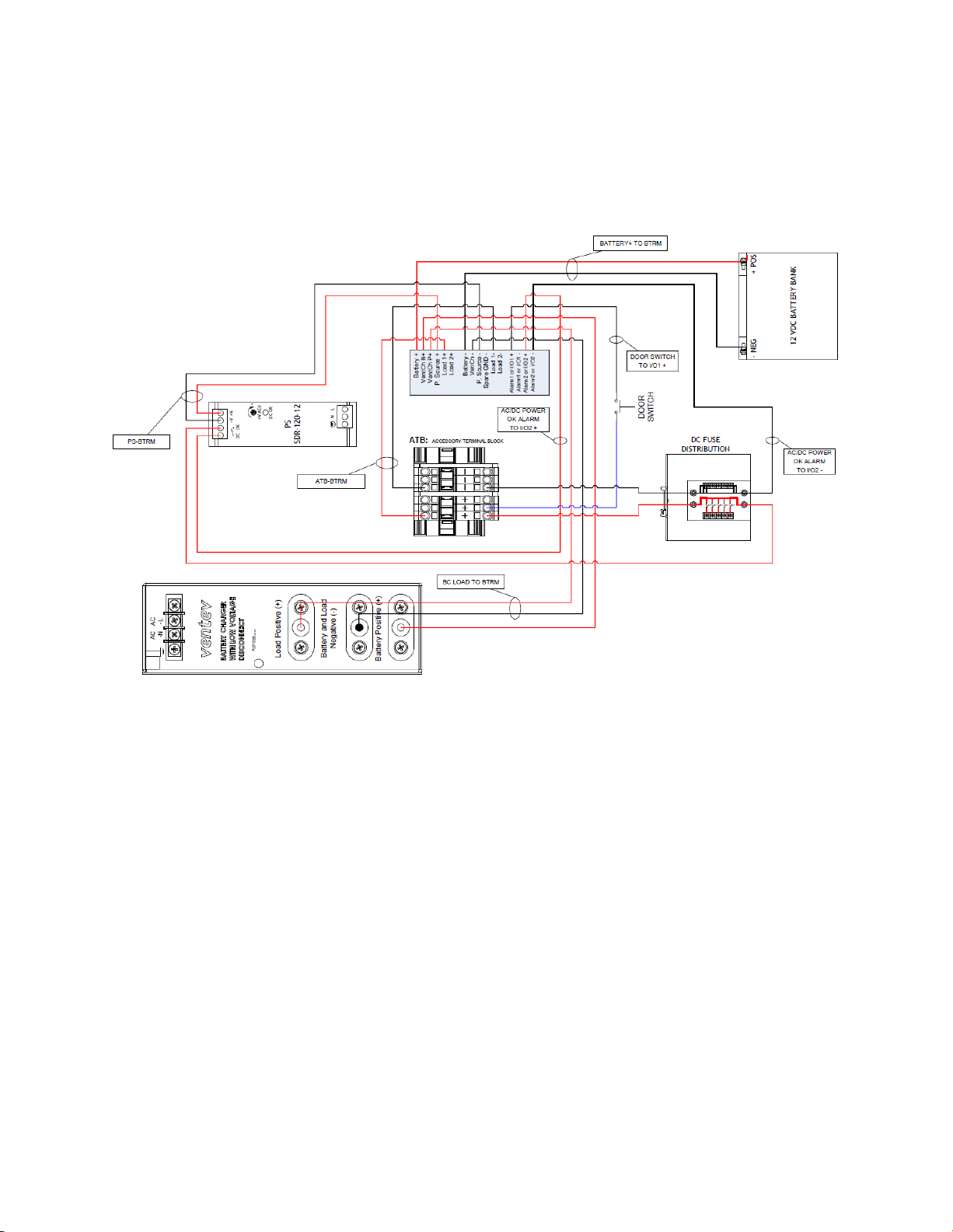
4. System Description
4.1. Overall System Connection Diagram
4.2. System Connector Overview
4.2.1. Power Supply In Power Jack (P. Source +/ - and VenCh P+)
The BTRM must be connected to the load power supply in order to energize the
load while the battery charger is charging the battery.
4.2.2. Battery Charger In Power Jack (VenCh B+/ -)
The BTRM must be connected to the battery charger in order to charge the
battery bank after the battery capacity test is performed.
4.2.3. Battery In Power Jack (Battery +/-)
The battery bank must be connected directly to the BTRM in order to perform
the battery capacity test.
4.2.4. Alarm Connector (Alarm1 or I/O1, Alarm2 or I/O2)
BTRM has two independent, isolated relay contacts for alarm indication.
Contacts are normally open when power is off. The user can select normally
open or normally closed under an alarm condition. Do not exceed the contact
Page 6

VENTEV INNOVATIONS BTRM200 Battery Test Remote Monitoring System – User Guide V1.0
6
maximum relay ratings of 60 Volts, 80 ma. Do not use to directly operate AC line
connected equipment.
5. Basic setup
5.1. Connecting unit to a PC
Notes on accessing a BTRM over Ethernet:
Technically you should be able to plug the device into your current network, regardless of
how your current network IP addressing is set up, and be able to reach the BTRM’s Status
and Setup web page by entering its IP address (found on the BTRM front label) in a Web
Browser on a local computer. However, in practice, not so easy, due to a wide variety of
possibly incompatible network addressing and firewall configurations. These difficulties
occur most often if someone else has set up the network settings, and in particular where
these settings are “managed” by software installed on your computer by your internet
provider or corporate IT departments.
To avoid these potential network issues at the initial evaluation stage it is best to connect
both your computer and the device to a hub/network switch (one that is not connected to
the rest of your network) or directly connect your computer to the BTRM with a crossconnected Ethernet cable.
5.2. Initial Power up to set IP address
To power up the device, connect the battery to the BTRM. Power up the power supply
and battery charger. The BTRM starts in self-test mode for 5 to 15 seconds. PB1 and PB2
push button LEDs will blink.
Once the device is power up and cabled to the Ethernet, the GREEN LED will illuminate
on the Ethernet connector and startup should be complete within 30 sec.
Page 7

VENTEV INNOVATIONS BTRM200 Battery Test Remote Monitoring System – User Guide V1.0
7
5.3. Accessing your host computer’s network settings
From the start button select Control Panel -> Network and Internet ->Network
Connections
Select the adapter that you plan to use and from the File menu, select properties.
This will bring up the properties window, shown on
the right.
Scroll down to the Internet Protocol Version 4
(IPv4) item, select it, and then select “properties”.
This will bring up the window to allow manual
configuration of the network adapter’s IP
addresses.
Page 8
VENTEV INNOVATIONS BTRM200 Battery Test Remote Monitoring System – User Guide V1.0
8
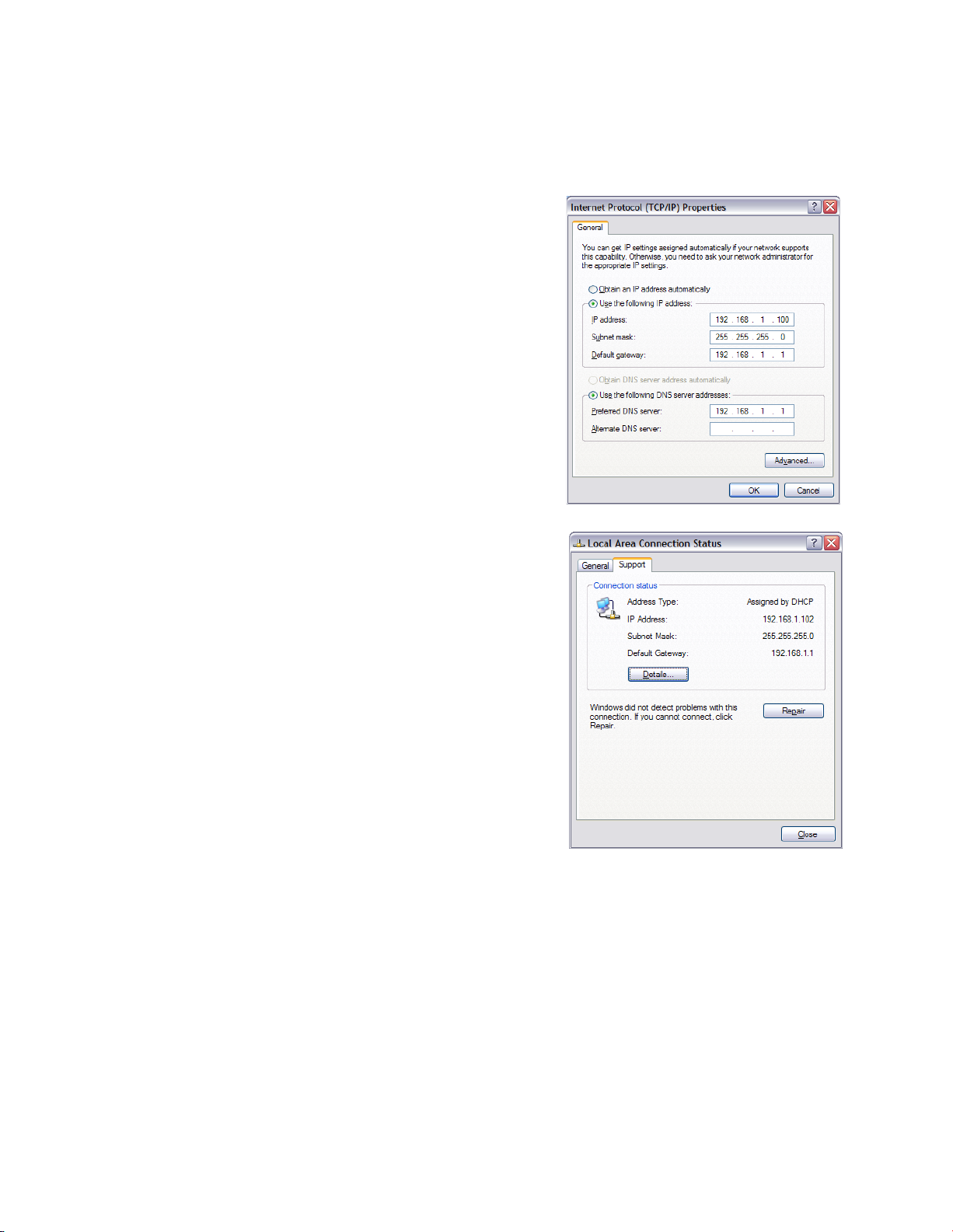
5.4. Setting IP address information for BTRM default
Using a direct connection to the device with a
cross connected cable or using a network switch
(hub), use the manual IP settings shown on the
right. This property dialog can be found in the
TCP/IP properties, which is a sub dialog of the
Network Connections Properties, both found in
Control Panel Network Connections.
(Typically the default gateway and DNS server
need not be entered.)
If using a router, check your local area connection settings to see if the router gateway
address is the same as the default device gateway
of 192.168.1.1. If it’s not, you will need to use a
direct connection as described above to change
the device gateway address to match the router’s
gateway address.
5.5. Verify IP address information
For the initial configuration of the BTRM and to change Network IP settings for
placement in an IP based network you will need to connect the BTRM directly to your
PC. Once connected to your PC you will be able to configure the BTRM to match your
network settings.
Page 9
VENTEV INNOVATIONS BTRM200 Battery Test Remote Monitoring System – User Guide V1.0
9
You will need the following information from your network administrator to add the
BTRM to your IP Network:
IP Address – we recommend using a static IP address for the BTRM
Gateway – what is the IP address of the Gateway of your network
Subnet Mask – what is the mask of your network
Primary DNS – IP address of the primary DNS server for your network
Once you have your connection made to you laptop or PC you will need to record your
IP address and verify connection to the BTRM.
NOTE: It may be necessary to give your PC or Laptop a static address to access the BTRM
default network.
Example: IP Address: 192.168.1.200
Subnet mask: 255.255.255.0
Use the following screen shots to guide you into finding your IP address and record your
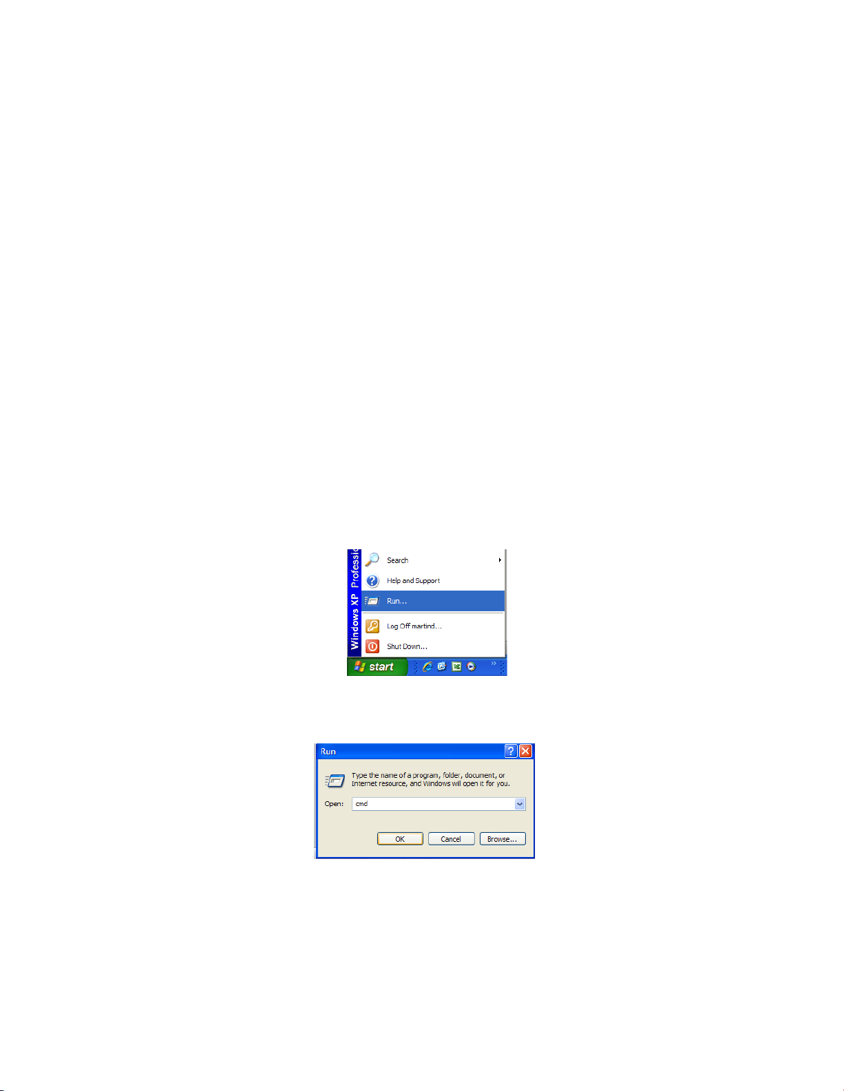
address for use later.
1. Click Start and then Run.
2. In the window type cmd and click OK.
Page 10
VENTEV INNOVATIONS BTRM200 Battery Test Remote Monitoring System – User Guide V1.0
10
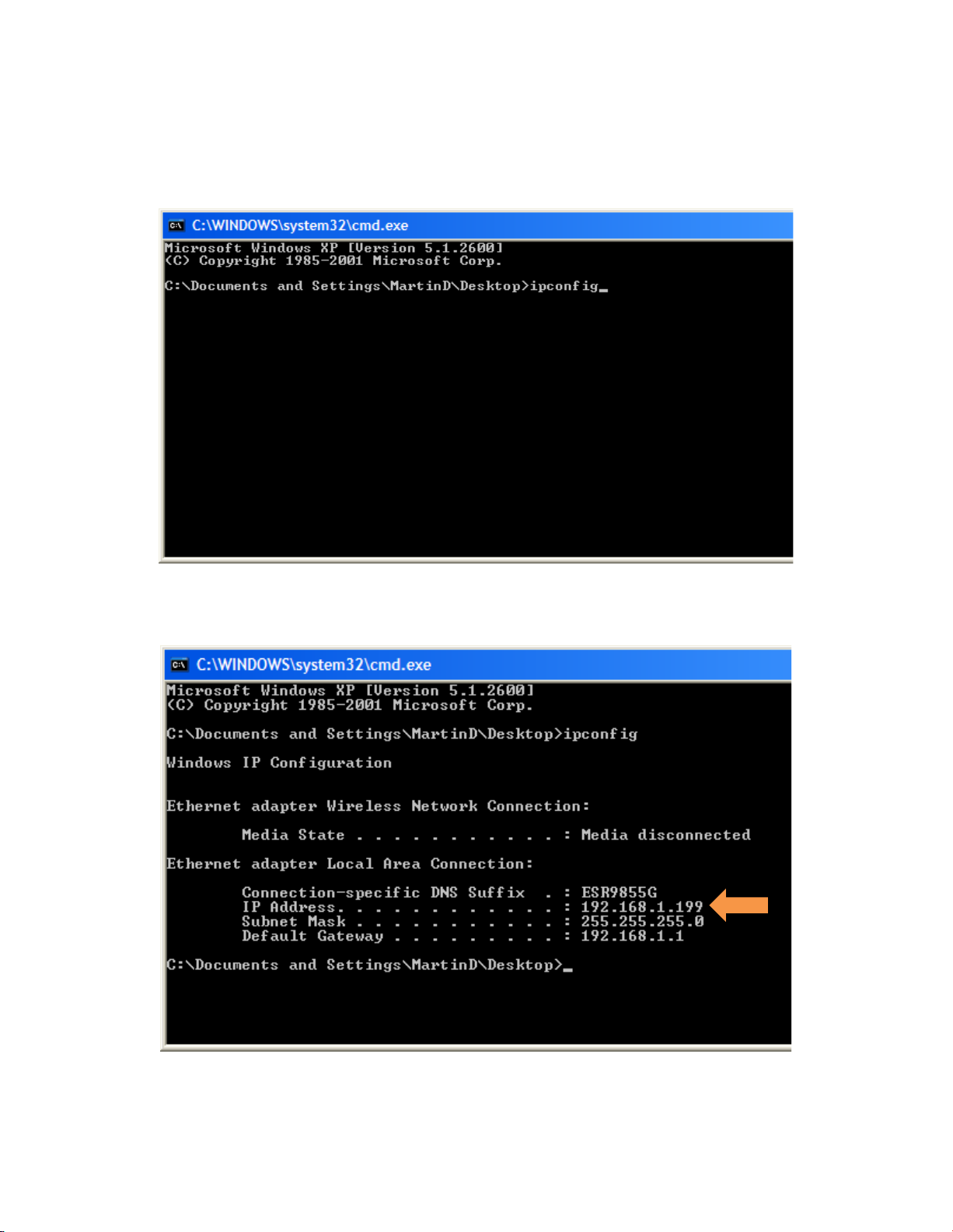
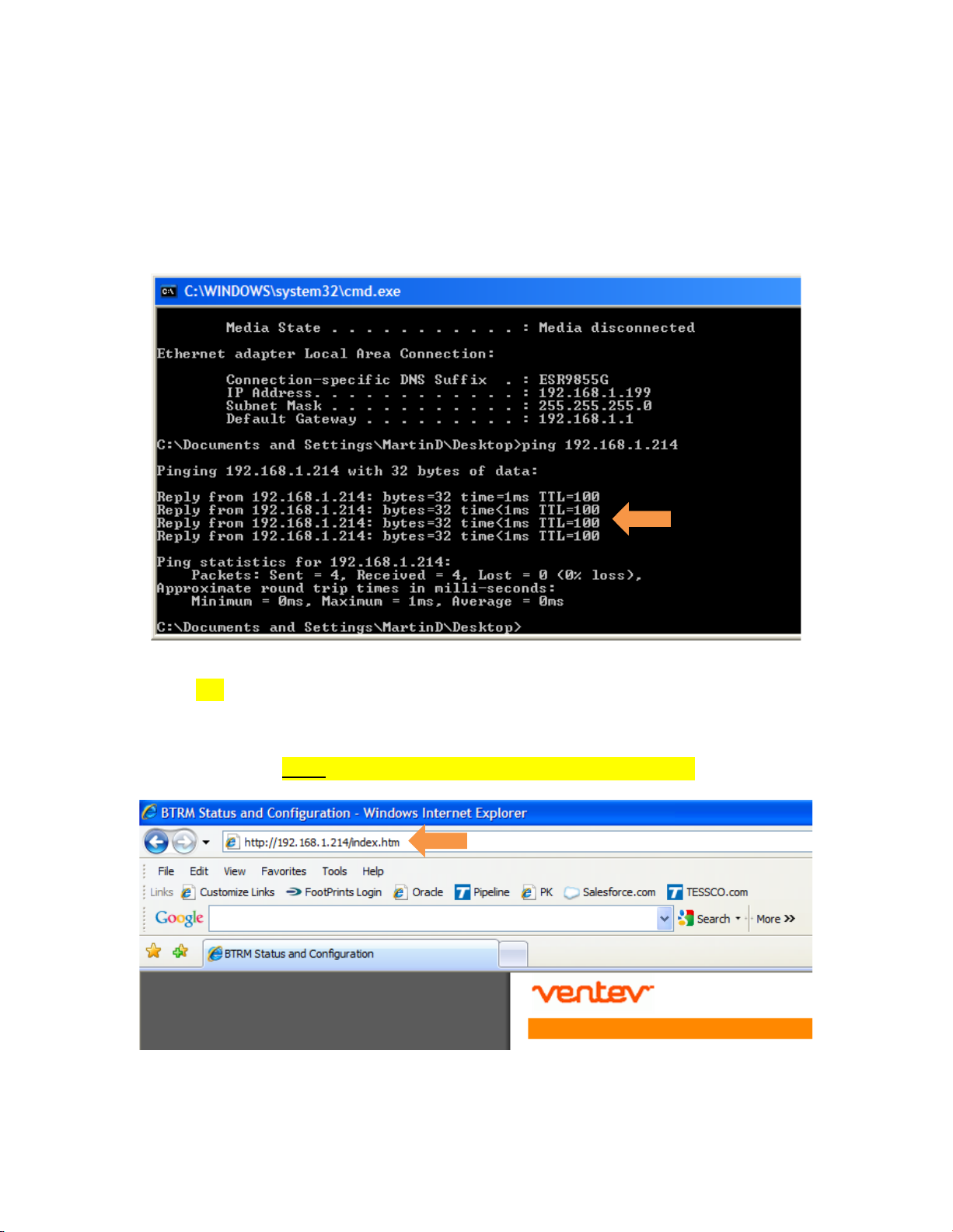
3. Type ipconfig then <Enter>.
4. Record your IP Address
Page 11
VENTEV INNOVATIONS BTRM200 Battery Test Remote Monitoring System – User Guide V1.0
11
5. Verify connectivity to the BTRM by sending a Ping command to the BTRM’s
default IP address: PING 192.168.1.214 <Enter> you should receive four REPLY
messages from the BTRM.
6. Open a New Web Browser Session (Internet Explorer, Firefox or Google Chrome)
and type in the address of the BTRM (default is 192.168.1.214) and click go or
<enter>. If everything is set up correctly you should see the System Status of the
BTRM. Note: The Status light blinks when the BTRM is active.
Page 12
VENTEV INNOVATIONS BTRM200 Battery Test Remote Monitoring System – User Guide V1.0
12
Page 13

VENTEV INNOVATIONS BTRM200 Battery Test Remote Monitoring System – User Guide V1.0
13
6. Unit Deployment
6.1. Mounting
The BTRM needs to be mounted in a water-proof location. Typically in a cabinet with
access to DC power. Use the DIN rail clip on the BTRM to secure to the DIN rail on the
enclosure back plate wall.
6.2. Wiring Battery Connection
Connect the battery connectors from the BTRM to the battery bank per system
configuration diagram **.
6.3. Wiring Power Supply Connections
Connect the BTRM power supply connections to the load power supply per system
configuration diagram **.
6.4. Wiring battery Charger Connections
Connect the BTRM battery charger connections to the battery charger per system
configuration diagram **.
** see section 4.0 for system connection diagram
6.5. Alarm Connections
Alarm connections are sets of normally open / closed contacts. These contacts are
isolated from the BTRM power source, and do not provide power. They can be used to
alert the Network Operations Center by connecting the alarms to your systems existing
alarm signaling pairs. Alternatively, the alarm contacts can be used to operate external
DC relays that then can be used to control alarm lights or audible alerts. Provided that
the contact ratings (60V, 80 ma) are not exceeded.
6.6. Clearing Battery Test Data
To clear test data from the BTRM memory, press and hold button PB2 for 15 seconds
until the LEDs flash.
7. Web Interface Menus
The BTRM will need to be configured to match your network settings as well as your
email and SNMP notification if those features are to be used. See section 5 for IP
addressing setup. The default Web page address of the BTRM is 192.168.1.214.
Once the BTRM is connected, enter this number into your web browser.
Page 14

VENTEV INNOVATIONS BTRM200 Battery Test Remote Monitoring System – User Guide V1.0
14
The Screenshots included with each sub heading will explain the different menus of the
BTRM user interface. This interface allows you to remotely configure and change
settings across the network.
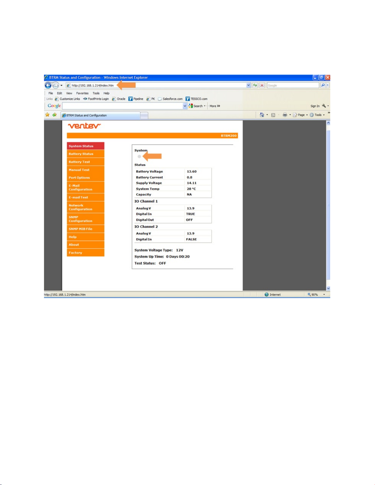
7.1. System Status Page
This screen displays an overview of the status on the BTRM. You can quickly see any
alarms occur by watching this screen.
7.1.1. System Status Indicator
If the web browser has a connection to the unit, the system indicator will toggle
between grey and green once a second.
7.1.2. Battery Voltage
This is the measurement of the battery voltage.
Page 15

VENTEV INNOVATIONS BTRM200 Battery Test Remote Monitoring System – User Guide V1.0
15
7.1.3. Battery Current
This is the measurement of the battery current.
Negative battery current Battery is powering the load.
Positive battery current Battery is being charger by battery charger.
7.1.4. Supply Voltage
This is the measurement of power supply voltage.
7.1.5. System Temperature
This is the measurement of the enclosure temperature.
7.1.6. Capacity
This is the measurement of the battery’s capacity level. This reading is present
after the first test is completed.
7.1.7. IO Channel 1 – Analog V
This is the measurement of the voltage present across contact number 1.
7.1.8. IO Channel 1 – Digital In
This is the logic setting for IO Channel 1 (see port options menu).
TRUE The logic level voltage for the port has been met. An alarm
message has been sent.
FALSE The logic level voltage for the port has not been met. No alarm
message has been sent.
7.1.9. IO Channel 1 – Digital Out
This indicates that the IO Channel 1 relay has been set to indicate a battery
relate fault (see port options menu).
OFF The relay is set for normal operation.
ON The relay is set to indicate a battery fault as diagnosed by the
BTRM.
Page 16

VENTEV INNOVATIONS BTRM200 Battery Test Remote Monitoring System – User Guide V1.0
16
7.1.10. IO Channel 2 – Analog V
This is the measurement of the voltage present across contact number 2.
7.1.11. IO Channel 2 – Digital In
This is the logic setting for IO Channel 2 (see port options menu).
TRUE The logic level voltage for the port has been met. An alarm
message has been sent.
FALSE The logic level voltage for the port has not been met. No alarm
message has been sent.
7.1.12. System Voltage Type
Record of the voltage the system is operating at.
7.1.13. System Up Time
Record of the time the system has been operational.
7.1.14. Test Status
This indicates if the battery capacity test has been enabled.
Page 17

VENTEV INNOVATIONS BTRM200 Battery Test Remote Monitoring System – User Guide V1.0
17
7.2. Battery Status Page
7.2.1. Capacity Test Settings Results.
This field displays the time stamp for the last battery capacity test was
performed, the average load current, and the average enclosure temperature
the test was performed at.
7.2.2. Current Status.
This field displays the estimated time to perform the battery capacity test. The
test is terminated when the battery voltage goes below 11 Vdc for a 12 Vdc
system or 22 Vdc for a 24 Vdc system. This is based on the battery capacity
curves for lead acid batteries and the average load current of the system. The
field also displays the minimum run time for the battery capacity test and the
status of the last test performed.
Page 18

VENTEV INNOVATIONS BTRM200 Battery Test Remote Monitoring System – User Guide V1.0
18
7.3. Battery Test Page
This page is used to enable the battery capacity test and customize the test. The user
can set the time between the tests and the length of the capacity test is performed.
Page 19

VENTEV INNOVATIONS BTRM200 Battery Test Remote Monitoring System – User Guide V1.0
19
Manual Test Page
7.3.1. Manual Test
This allows the user to manually start the battery capacity test at their
discretion.
7.3.2. Capacity IO Check
This allows the user to set the battery capacity level at which the test terminates.
7.3.3. Reset Battery Data and Setting to Defaults
This allows the user to reset the BTRM test parameters.
7.4. Port Options Page
This allows the user to enable the IO channels and the system operation voltage.
Page 20

VENTEV INNOVATIONS BTRM200 Battery Test Remote Monitoring System – User Guide V1.0
20
7.4.1. IO Channel 1
7.4.1.1. Analog Input 0-32V
This allows the user to enable an analog input level for triggering alarms
from external sources (door switches, solid state relays, etc.).
7.4.1.2. Digital Input Alarm if < 1V
This allows the user to enable a digital input logic levels that is less than 1
volt to trigger an alarm from external sources (door switches, solid state
relays, etc.).
7.4.1.3. Digital Input Alarm if > 2V
This allows the user to enable a digital input logic levels that is greater
than 2 volt to trigger an alarm from external sources (door switches, solid
state relays, etc.).
Page 21

VENTEV INNOVATIONS BTRM200 Battery Test Remote Monitoring System – User Guide V1.0
21
7.4.1.4. Low Capacity Alarm
This allows the user to enable the channel relay to indicate a battery
relate fault
Digital Out Normally Open The relay closes when a fault is indicated.
Digital Out Normally Low The relay opens when a fault is indicated.
7.4.2. IO Channel 2
7.4.2.1. Analog Input 0-32V
This allows the user to enable an analog input level for triggering alarms
from external sources (door switches, solid state relays, etc.).
7.4.2.2. Digital Input Alarm if < 1V
This allows the user to enable a digital input logic levels that is less than 1
volt to trigger an alarm from external sources (door switches, solid state
relays, etc.).
7.4.2.3. Digital Input Alarm if > 2V
This allows the user to enable a digital input logic levels that is greater
than 2 volt to trigger an alarm from external sources (door switches, solid
state relays, etc.).
7.4.3. System Voltage
Allows the user to select whether the system operates at 12 V or 24 V.
Page 22

VENTEV INNOVATIONS BTRM200 Battery Test Remote Monitoring System – User Guide V1.0
22
7.5. Email Configuration Page
This page allows the user to configure information needed for the BTRM to access an
email server and deliver messages to the destination email address along with two
customizable text strings to provide additional situation detail in the email alert.
7.5.1. Contact and Location
While these text strings that are included with outgoing email and SNMP
notifications to aid in identifying the site location and manager, they can be used
for any purpose.
Contact: Enter the name of the contact person responsible for the site.
Location: Enter a short description of the site location the BTRM is monitoring
Page 23

VENTEV INNOVATIONS BTRM200 Battery Test Remote Monitoring System – User Guide V1.0
23
The following information should be obtained from your Network Administrator to
setup the SMTP server.
7.5.2. Port
Enter the Port number the SMTP server uses, select SSL if it uses Secure Socket
Layer. Normally this port is 25. For secure servers other port numbers are
typically used such as Secure SMTP (SSMTP) - port 465 and Secure IMAP (IMAP4SSL) - port 585.
7.5.3. User name and Password
If you are using your dedicated IP provider’s internet service and its email server
you will likely leave these two items blank. If you are on a public network, most
likely you will need to access a secure server using SSL. In this case the user
name and password will likely be required.
7.5.4. Server Address
This is the IP address or IP name of your outgoing email server. For example
Gmail’s server is smtp.gmail.com
7.5.5. Destination Email Address
The BTRM will send the email notifications to this email address.
Page 24

VENTEV INNOVATIONS BTRM200 Battery Test Remote Monitoring System – User Guide V1.0
24
7.6. Email Test Page
Use this page to send a test email using the setting from the previous page.
If successful after several seconds, the web page will update to indicate that the
message has been successfully sent. If the page does not refresh after a minute, then
likely the message was not sent. Check you setting, and or try these setting using a
laptop and its email client to verify the connection and settings.
7.7. Network Configuration Page
This screen allows you to configure the Network settings on the BTRM. DO NOT change
any of the settings here unless you know what you are doing. These settings should be
configured under the direction of your network administrator.
Page 25

VENTEV INNOVATIONS BTRM200 Battery Test Remote Monitoring System – User Guide V1.0
25
Multiple BTRM’s could be active in the network at the same time. Each will have its own
IP address to allow for remote access and monitoring.
To access any BTRM in the network, open a web browser and type the IP address of the
BTRM into the address bar. Each BTRM should have their own unique address when
they are part of the same network.
7.7.1. Host Name
This name can be used in place of the IP address to get access to the BTRM.
7.7.2. IP address, Gateway, Subnet Mask
Enter the settings to match your network system.
Page 26

VENTEV INNOVATIONS BTRM200 Battery Test Remote Monitoring System – User Guide V1.0
26
7.8. DNP3 and Modbus
Selection and setup of DNP3 and Modbus Master and BTRM Device addresses and
communications protocol selection.
7.8.1. Addressing
Master and Device addressing supports values between 0 and 65535.
Confirm with your selected protocol what address values are allowable.
7.8.2. DNP Retry Settings
Retry settings for unsolicited messages range between 0 (no retries) and 254
with setting of 255 causing continuous retries.
Elapsed time between retries 0 to 255 seconds (settings below 5 seconds not
recommended).
Page 27

VENTEV INNOVATIONS BTRM200 Battery Test Remote Monitoring System – User Guide V1.0
27
7.8.3. Communications Interface
7.8.3.1. TCP/IP
Configurable :TCP/IP Port (Default 20000)
Configurable: TCP/IP Unsolicited message destination IP address
7.8.3.2. RS232
BTRM supports a 3 wire RS232 using standard connections on DB9
connector.
Baud Rates: Selectable 9600, 19200
Format: Data 8 bits, No Parity, Stop Bits 1
7.9. SNMP Configuration Page
Setting the community strings provides SNMP with basic password protection. User has
a choice of 3 read only and 3 write only strings. Most SNMP browsers are configured to
use the typical default strings, public, read, or write. When a string is changed read or
write, the software used to connect to the BTRM must also use the same strings for
read write access. If you wish to use SNMP alerts the Read and Write strings will need
to be configured to match your network. These settings should only be changed by a
Network Administrator or by someone who understands the proper settings for your
network.
Leaving a field blank will disable it.
Page 28

VENTEV INNOVATIONS BTRM200 Battery Test Remote Monitoring System – User Guide V1.0
28
NOTE: SNMP configurations may be confusing. Please consult your Network
Administrator to assist you in the SNMP configuration and setup.
Page 29

VENTEV INNOVATIONS BTRM200 Battery Test Remote Monitoring System – User Guide V1.0
29
7.10. SNMP MIB File Page
The BTRM is provided with a Management Information Base File (a text file
ending in “.mib”). This file allows a MIB browser to translate the numeric OID
numbers into text descriptions. This can be down loaded in the MIB browser
from the BTRM firmware using this webpage.
Page 30

VENTEV INNOVATIONS BTRM200 Battery Test Remote Monitoring System – User Guide V1.0
30
7.11. Help Page
This page provides the user default IP and SNMP notification setup information.
Page 31

VENTEV INNOVATIONS BTRM200 Battery Test Remote Monitoring System – User Guide V1.0
31
7.12. About
This page provides the user with web page and firmware revision information.
8. SNMP Functionality
8.1. Network SNMP Monitoring
Simple Network Management Protocol (SNMP), used by most Network Operations
Centers (NOC), is a protocol that allows the NOC to retrieve parameters, set
parameters, and receive Alert Notifications from Ethernet connected appliances though
a common interface and language. Each network appliance feature, that can be read or
written to, will have a numeric string assigned to it. For example system description
(sysDesc) is .1.3.6.1.2.1.1.1.0.
Page 32

VENTEV INNOVATIONS BTRM200 Battery Test Remote Monitoring System – User Guide V1.0
32
For Network SNMP functionality, consult your network administrator for SNMP setup
and configuration parameters and how the BTRM should be configured for your specific
SNMP requirements and trap receivers.
8.2. SNMP Monitoring through a MIB Browser
In order to accept SNMP messages being sent from the BTRM you will need to have an
SNMP monitoring system in your network or a MIB browser loaded onto your laptop.
A MIB browser can be used to capture SNMP traps in place of a network SNMP trap
receiver. The MIB Browser can be loaded onto a PC or Laptop for monitoring of BTRM
SNMP Traps. The MIB browser will need to be on the same network as the BTRM in
order to receive the messages.
SNMP network access can be had from interfaces as simple as a command line
interface available in Windows, Linux, and other operating systems, or using a
dedicated software browser like the one shown below from iReasoning, available at
www.iReasoning.com, to larger packages such as HP Openview designed to support
and manage larger networks.
IMPORTANT: Once the MIB Browser is loaded you will need to load the BTRM MIB file.
You can down load the BTRM MIB file from the BTRM via the SNMP MIB file page on
you web browser.
8.2.1. Install MIB Browser
1. Download MIB Browser from http://www.ireasoning.com.
2. Open MIB Browser Folder.
3. Click on the Setup.exe file.
4. Click Run and Follow the installation instructions.
5. Click Close when the installation has completed.
6. Launch the MIB Browser.
8.2.2. Install SNMP MIB File
1. In the MIB Browser – Click on the File Tab.
2. Select Load MIBs.
3. In the Open Window, locate the file called btrm2_mib_yyyy-mm-dd.mib (This
traps file should be located in the software files included with your BTRM).
4. Click on the btrm2_mib_yyyy-mm-dd.mib.
5. Click Open.
Page 33

VENTEV INNOVATIONS BTRM200 Battery Test Remote Monitoring System – User Guide V1.0
33
8.2.3. View BTRM via MIB Browser
1. Once the MIB browser is loaded, click on the desktop icon to launch it. You
will see the main screen that should look similar to the one below. In the
Address field type in the IP address of the BTRM, 192.168.1.214. Expand the
folders on the left menu and highlight private.
2. If you have changed the community strings from the default values, use the
advanced menu item to update the browsers read write community strings
to match the BTRM.
Page 34

VENTEV INNOVATIONS BTRM200 Battery Test Remote Monitoring System – User Guide V1.0
34
3. From the operations pull down menu, select “Walk” and click Go.
Page 35

VENTEV INNOVATIONS BTRM200 Battery Test Remote Monitoring System – User Guide V1.0
35
4. You should see data results begin to fill up in the main window Results Tab.
8.2.4. Configure Trap Receiver
In order to receive SNMP Traps (alert messages) you will need to setup your MIB
browser to receive them. This means you need to setup your TrapReceiver so that the
BTRM knows where to send the traps. So in the next you will setup the TrapReceiver IP
address. (You will set this to the IP address of your laptop that you recorded earlier).
Page 36

VENTEV INNOVATIONS BTRM200 Battery Test Remote Monitoring System – User Guide V1.0
36
1. In the Results Table locate the line that says trapReceiverAddress.0 , right
click on the line and select “set”.
Page 37

VENTEV INNOVATIONS BTRM200 Battery Test Remote Monitoring System – User Guide V1.0
37
2. Enter the IP Address of your PC or Laptop in the Value field and click OK.
Note: In order to receive SNMP messages the BTRM and the associated PC
or Laptop must be on the same network or be able to communicate across
networks. Verify connectivity by pinging the BTRM with your PC or laptop. If
you receive a reply you should be able to receive SNMP messages.
3. If your entry was successful you will see a SET succeeded window.
8.2.5. Cannot Bind to Port 162 Error Message
Depending on your computer configuration you may get an error message pop up that
says that you cannot bind to port 162. SNMP uses port 162 and sometimes Windows
has an active SNMP server running that is using port 162. If you get this message you
will need to follow the steps below to kill the process using the port.
Page 38

VENTEV INNOVATIONS BTRM200 Battery Test Remote Monitoring System – User Guide V1.0
38
Steps to shut down Application binding to Port 162
1. Load CurrPorts software – Download CurrPorts software from
http://download.cnet.com/CurrPorts.
2. Click on the cports.exe icon to launch the software
3. When the software opens click Run.
4. Locate the application that is using port 162 by finding it under the Local Port
column. Click on the line to highlight it.
Page 39

VENTEV INNOVATIONS BTRM200 Battery Test Remote Monitoring System – User Guide V1.0
39
5. Right click on the highlighted line (ensure you are on the line of the process using
port 162) select “Kill Processes Of Selected Ports”
Page 40

VENTEV INNOVATIONS BTRM200 Battery Test Remote Monitoring System – User Guide V1.0
40
6. Select Yes on the window that asks if you want to kill the process.
7. You should now be able to return to the MIB browser and continue to open the
Trap Receiver.
8.2.6. Open Trap Receiver
1. In order to see the SNMP alert messages coming in you will need to open the trap
receiver Tab. To do this, in the MIB Browser, go to Tools and select Trap Receiver.
Page 41

VENTEV INNOVATIONS BTRM200 Battery Test Remote Monitoring System – User Guide V1.0
41
2. You should now see a Trap Receiver Tab in the main window of the MIB Browser.
3. Now, in order to see the SNMP traps coming in you need to throw the BTRM into an
alarm by removing one contact loop circuit at a time. There are various ways to
break the contact loop circuit depending on the BTRM configuration.
a. Door Switch
i. Push the door switch in and hold for approximately 10 seconds. This
simulates the enclosure door beeing closure.
ii. Release the door switch.
iii. In a few seconds you should see an SNMP message alert come into
the trap receiver in the MIB Browser.
b. AC/DC OK Indication
i. When you remove the AC power from the enclosure, you should see
an alarm on the BTRM.
Page 42

VENTEV INNOVATIONS BTRM200 Battery Test Remote Monitoring System – User Guide V1.0
42
ALSO NOTE: The software alarms in the BTRM user interface and the SNMP alert messages, the
BTRM is also sending out email message alerts to the email address that you configured in the
email setup section.
Page 43

VENTEV INNOVATIONS BTRM200 Battery Test Remote Monitoring System – User Guide V1.0
43
Sreenshot of the System Status Screen showing alarm on IO Channel 1. The Digial In “TRUE”
logic level indicates that the voltage thrush hold for the port has been met. An alarm message
has been sent.
Page 44

VENTEV INNOVATIONS BTRM200 Battery Test Remote Monitoring System – User Guide V1.0
44
Screenshot of SNMP Messages showing alarm on IO Channel 1. If you click on the SNMP
messages you can read the detailed description including timesstamp and location the message
was sent from.
8.3. Further Reading
Douglas Mauro, Kevin Schmidt. Essential SNMP, Second Edition. O'Reilly Media, Inc.
9. Additional Protocols
9.1. DNP3
9.1.1. Overview
9.1.2. Data Link Layer
BTRM2 DNPV2.0 Currently no support for data link layer commands
9.1.3. Application Layer
9.1.3.1. Function Support
Dec
Hex
Function
0
0
Confirm
1
1
Read
2
2
Write
Page 45

VENTEV INNOVATIONS BTRM200 Battery Test Remote Monitoring System – User Guide V1.0
45
5
5
Direct Operate
13
D
Cold Restart
15
F
Initialize Data
20
14
Enable Unsolicited
21
15
Disable Unsolicited
129
81
Response
130
82
Unsolicited Response
9.1.3.1.1. Enable Disable Unsolicited Event Status
BTRM allows enable and disable of unsolicited events. Status can be
read from Binary Point 3
9.1.3.2. Groups and Variations
Object /Group
Object /Group
Type
Variation
Description
01
Binary Input Status
Static
02
1 byte input status with flag
30
Analog Input Status
Static
04
16 bits without flag
10
Binary Output Status
Static
02
1 byte output status with flag
10
Binary Output Write
Static
01
Write using q00 start = stop
40
Analog Output Status
Static
02
16 bits with flag
41
Analog Output
Static
02
16 bits with flag 0x01
60
Class 1 Static Data
Static
01
Class 1 Data
60
Class 2 Event Data
Static
02
Class 2 Data
9.1.3.3. Qualifiers
Qualifiers (Hex)
Used In a request
Range
Index
00
a range of points or single point
8 bits
8 bits
06
all points range and index 8 bits
8 bits
8 bits
17
list of unrelated points
8 bits
8 bits
9.1.3.4. Binary Input Status Points
Point
Description
State
Value
0
Low Battery Capacity
Low
0x81
1
Low Battery Voltage
Low
0x81
2
DNP3 Unsolicited Enabled
Enabled
0x81
3
Aux IO Channel 1 Digital In
Tripped
0x81
4
Aux IO Channel 2 Digital In
Tripped
0x81
5
Any Fault Flag
Tripped
0x81
Page 46

VENTEV INNOVATIONS BTRM200 Battery Test Remote Monitoring System – User Guide V1.0
46
9.1.3.5. Analog Input Status Points
Point
Description
Units
0
Battery Voltage
millivolts
0 to3200 mv
1
Charger Voltage
millivolts
0 to3200 mv
2
Battery Current
±milliamps
± 32000 ma
3
Temperature
±°C
4
Battery Minimum Runtime
Minutes
0 to 3200 minutes
5
Battery Runtime Estimate
Hours
6
Battery Test Temperature
±°C
7
Battery Test Schedule Time
Hours
0 to 500 Hrs
8
Battery Test Next Time
Hours
0 to 500Hrs
9
Aux IO Channel 1 Voltage
millivolts
0 to3200 mv
10
Aux IO Channel 2 Voltage
millivolts
0 to3200 mv
11
Firmware Version
format xx.xx -> 130 = v1.30
9.1.3.6. Analog Output Status Points
Point
Description
State
0
Battery Minimum Runtime
Minutes
0 to 3200 minutes
1
Battery Test Schedule Time
Hours
0 to 500Hrs
2
Battery Test Next Test Time
Hours
0 to 500Hrs
3
Aux IO Channel 1 Config
1,2,3
(see below)
4
Aux IO Channel 2 Config
1,2,3,4,5
(see below)
5
System Selection 12V /24V
1,2
1= 12v, 2 =24v
Page 47

VENTEV INNOVATIONS BTRM200 Battery Test Remote Monitoring System – User Guide V1.0
47
IO1
Function Control
Values 0,1,2,3,4
Read
Group 40 Variation 2
16bit Analog with
flag
Direct Operate
Group 41 Variation 2
16bit Analog with
flag
Direct Op Value
0
Analog
1
Digital Input Alarm if < 1v
2
Digital Input Alarm if > 2v
Low Capacity Alarm
3
Digital Out NC
4
Digital Out NO
IO2
Function Control
Values 0,1,2
Read
Group 40 Variation 2
16bit Analog with
flag
Direct Operate
Group 41 Variation 2
16bit Analog with
flag
Direct Op Value
0
Analog
1
Digital Input Alarm if < 1v
2
Digital Input Alarm if > 2v
9.1.3.7. Binary Output Status Point
Point
Description
State
Value
State
Value
0
Battery Data Reset
Session has Data
0x81
Data Empty
0x01
1
Battery LVD Status
LVD is enabled
0x81
LVD disabled
0x01
2
Battery Test Enable
Test is enabled
0x81
Test is disabled
0x01
3
Battery Start Test
Test running
0x81
Test not running
0x01
9.1.3.8. Binary Output Write to Points
Binary output points can be written to directly using Group 10 variation 01, using
Qualifier 0x00 (8 bit index and range).
Points must be written to individually, using matching start and stop values,
followed by the binary value "1" or "0" (See DNP_IEE-1815-2023 11.9.4.6)
Page 48

VENTEV INNOVATIONS BTRM200 Battery Test Remote Monitoring System – User Guide V1.0
48
To clear or enable write a "1", or to disable write a "0".
An xample to reset battery data, g10v01 q00 start 0 stop 0 value 1, would be to issue
an application layer write command of the form:
c5 02 0a 01 00 00 00 01
Point
Description
State
Value
State
Value
0
Battery Data Reset
Write to Enable
0x81
Write to Disabled
0x01
1
Battery LV Disconnect Enable
Write to Clear
0x81
Cleared
0x01
2
Battery Test Enable
Write to Start
0x81
Write to Stop
0x01
3
Battery Start / Stop Test
Write to Start
0x81
Write to Stop
0x01
9.1.3.9. Events
When Events are generated, they are reported via unsolicited messaging (if
enabled), or queue to the event list for reading when polling for Class 2 data, or
reading Binary events. Event points correspond to Binary Input Points.
Point
Description
State
Value
1
Low Battery Capacity Event
Tripped Event
0x81
2
Low Battery Voltage Event
Tripped Event
0x81
4
Aux IO Channel 1 Event
Tripped Event
0x81
5
Aux IO Channel 2 Digital In
Tripped Event
0x82
9.1.3.10.
9.2. Mod Bus
- expected Q3/2013
Page 49

VENTEV INNOVATIONS BTRM200 Battery Test Remote Monitoring System – User Guide V1.0
49
10. Additional Network Setup
10.1. IP Reset
To reset the device to its default IP address settings, hold Button PB1 for 20
seconds. All the LEDs will flash and the unit will restart with the default IP
settings listed on the device label.
Typically these settings are:
Unit IP 192.168.1.214
Subnet Mask 255.255.255.0
Gateway 192.168.1.1
10.2. Router Ports
If you need to access the device from outside of a local intranet (hosts computer
is on the WAN side of the device router), the appropriate ports will need to be
set on the router to which the host computer is attached and also the router to
which the device is attached.
One solution
Routers allow a single device to be set so that it can be reached by using the
router’s IP address. The same can be done for the host computer, sometimes
called –“placing the device in the demilitarized zone” (DMZ). Not as secure, but
much simpler as ports do not need to be forwarded. In this case the device IP
the Router WAN IP.
Opening Ports Method
When accessing the device from behind a router the device LAN IP address is
effectively hidden. In this case the port number is used to determine the final
destination.. Only the WAN IP address of the router is reachable. The host
computer then uses the router WAN IP as the destination IP address.
The Router then uses the messages destination port, and the routers port
forwarding table to direct to the appropriate device on the internal intranet.
For example:
Host Computer has internal LAN IP of 192.168.1.214
Its Router has WAN IP of 100.78.60.21
Device issues a SNMP notification to 100.78.60.21:162 (where 162 is the port
number)
Page 50

VENTEV INNOVATIONS BTRM200 Battery Test Remote Monitoring System – User Guide V1.0
50
The Router is the message destination. The Router looks at the message’s port,
checks its port forwarding table to see if the UDP port 162 is forwarded to a local
LAN IP address. If so, delivers it to that IP address (in this case the Host
Computer), otherwise the message is discarded.
10.3. Port Table
Function
Default Port Values
TCP/IP
UDP
Web Page Access (http)
80
SNMP Management Access
161
SNMP Notifications
162
Email
21
DNP3
20000
Firmware Update
16384
11. Specifications and Warranty
Electrical Specifications
Operating Voltage 9 to 32 VDC
Battery Max Current 10 A Continuous
Charger Max Current 10 A Continuous
Load 1 & 2 Combined Max Current 10 A Continuous
Battery and Charger
Voltage Measurement 0 to 32V ± 1%
Current Measurement 0 to 10 Amps ± 1%
Environmental
Temperature -20° C to +60° C
Humidity 5 % to 95% Non Condensing
Mechanical
Size 6.25” H X 2.8” D X 1.2” W
Weight 5.0 oz (142 g)
Mounting Din rail mounting
Warranty One Year
Page 51

VENTEV INNOVATIONS BTRM200 Battery Test Remote Monitoring System – User Guide V1.0
51
Note: Specifications subject to change without notice.
 Loading...