

TerraTrike Tour II Assembly Manual
www.TerraTrike.com - 800.945.9910
4460 40th St SE. Grand Rapids MI, 49512
USA
Assembly Guide
Pilot’s Handbook
Technical Illustration
&
Parts List

Table of Contents
Assembly Guide - Pg 1-15
Pg 1 - Serial Number & Boom Installation
Pg 2 - Rear Wheel Installation & Hubmount (Axle) Installation
Pg 3 - Idler Wheel Installation
Pg 4 - Steering Brace Installation & Tie Rod Installation
Pg 5 - Front Wheel Installation & Handlebar Installation
Pg 6 - Brake Caliper Installation
Pg 7-9 - Alignment
Pg 10 - Align Rear Derailleur Hanger & Rear Derailleur
Installation and Setup
Pg 11 - Front Derailleur Setup & Pedal Installation
Pg 12 - Chain Installation
Pg 13 - Handlebar Cable Housing Routing & Installation
Pg 14 - Seat Clamp Installation
Pg 15 - Seat Installation and Reector Installation
Owners Information - Pg 16-17
Pg 16 - Welcome, Unpackaging, Cautions/Safety, Riding Tips
Pg 17 - Warranty Information
Technical Drawing & Parts List - Pg 18-20
Pg 18 - Tour II Technical Drawing w/Part Numbers
Pg 19 - Tour II Parts List
Pg 20 - Seat Clamp Technical Drawing w/Part Numbers,
Seat Clamp Parts List
Boom Size Chart - Pg 21
Company Information - Pg 22
Assembly Guide
Dark Grey = Installation/Adjustment
PLEASE NOTE: Make sure you’re greasing bolts before installing them. Failure
to do so can cause “galling” to occur (heat and friction will fuse (weld) the fasteners
together). Adjustment will be impossible and not covered under warranty.
1
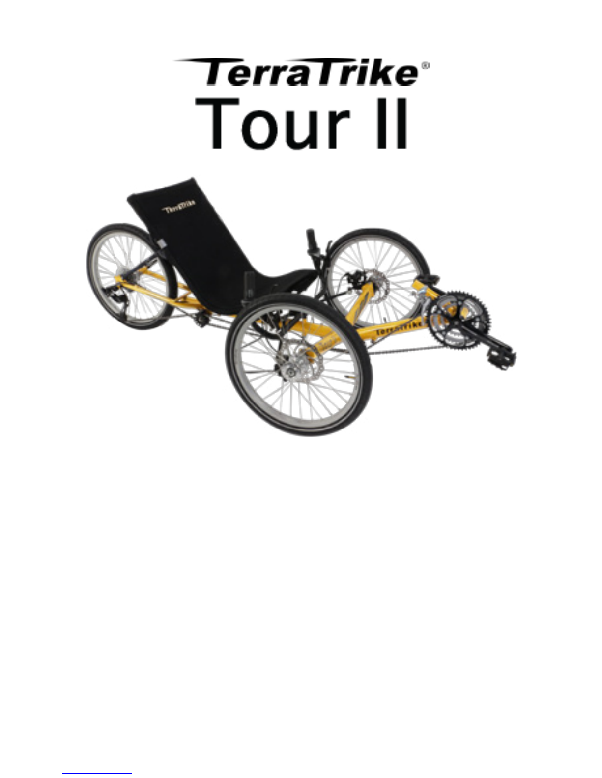
Locate/Record Serial Number
2
Boom Installation
Number is located under
the underside of the frame.
1
Boom must be slid all of the way
onto the boom receiver tube so that
none of the non-painted surface is
showing
Torque Spec: 100-125 in lbs
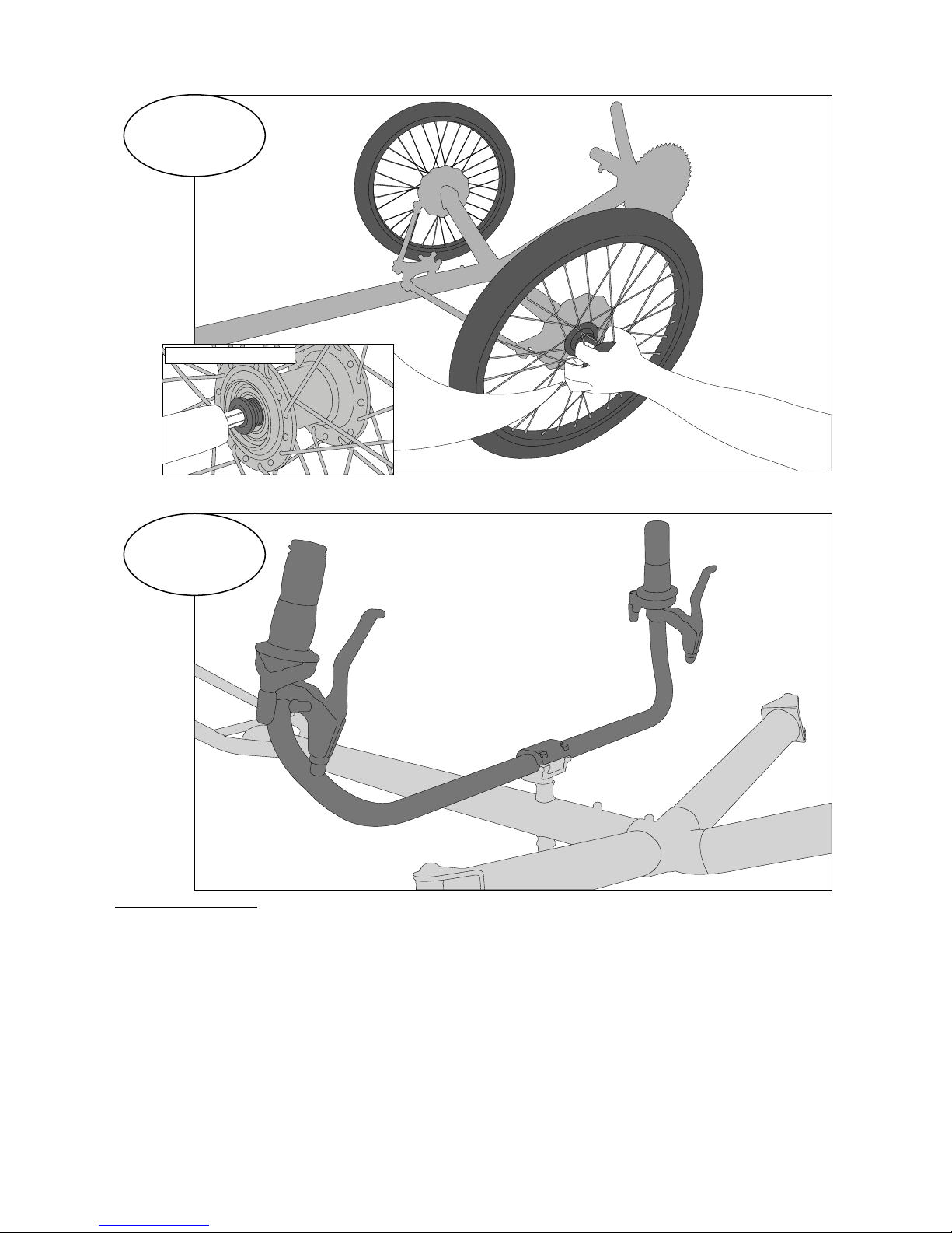
3
4
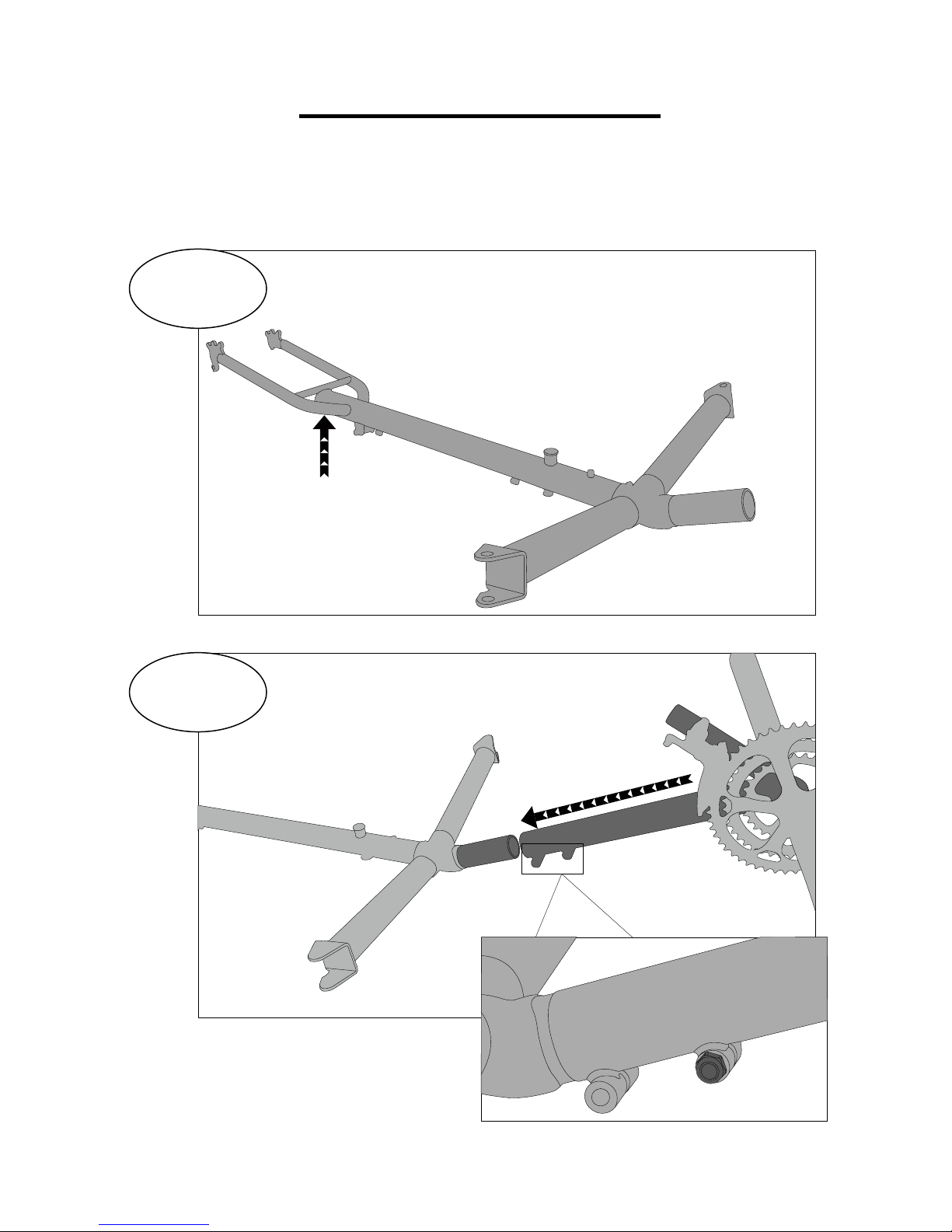
Rear Wheel Installation
Hubmount Installation
2
Tighten hubmount bolts completely. If
the hubmounts cannot rotate on the
kingpin easily, loosen bolts slightly
until they do. Failure to do so can
result in poor steering performance.
WARNING: please check the kingpins periodically.
Road vibration will cause them to loosen over time!
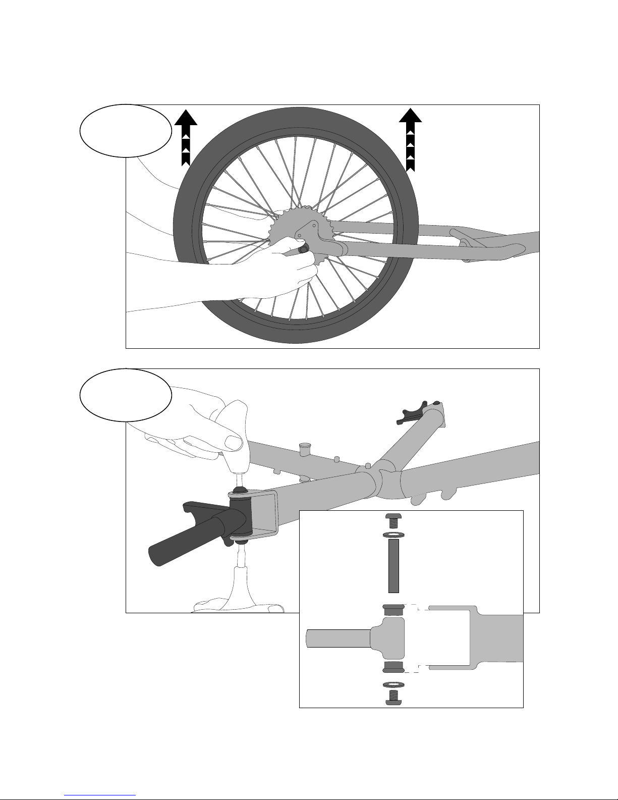
5
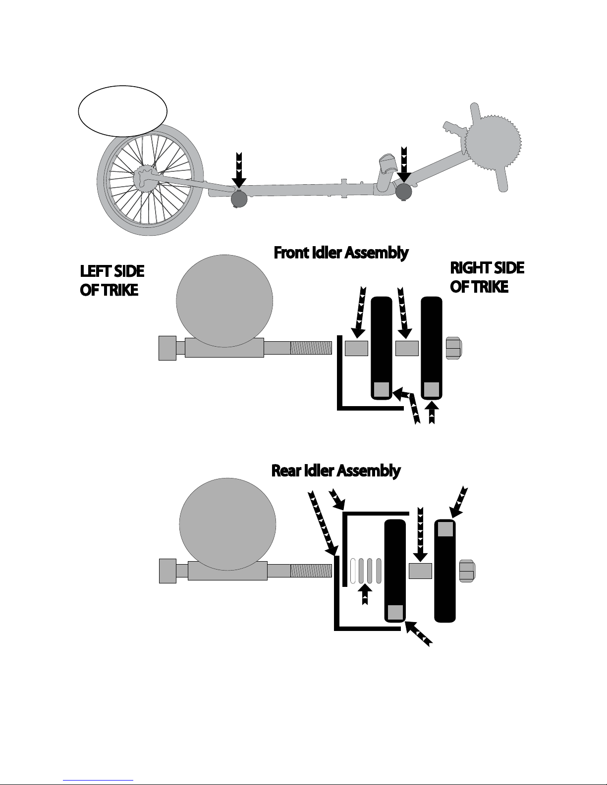
Idler Wheel Installation
M8 Flat
Washer
M8 x90 Bolt
M8 x90 Bolt
Idler Spacer
Idler Spacer
M8 Lock Nut
Idler L Bracket
Idler L Bracket
M8 Lock Nut
Idler Wheel
Idler Wheel
Chain Routing - under both Idlers
Chain Routing - under inside Idler
Chain Routing - over outside Idler
Trike Frame
Trike Frame
PLEASE NOTE: An Additional M8 washer (illustrated in white) may
be required for proper Idler spacing between “L” bracket and Idler.
RIGHT SIDE
OF TRIKE
LEFT SIDE
OF TRIKE
Front Idler Assembly
Rear Idler Assembly
IMPORTANT: Drive portion of chain must be routed on
the idlers closest (inside idlers) to the frame; “return”
portion of chain is routed on the outer idlers.
Idler Spacers
Rear Idler
Assembly
Front Idler
Assembly
3

6
Steering Brace Installation
7
Tie Rod Installation
Use M8 washers on the under side of the
steering brace tongue. Install between
steering tongue and tie rod end. THERE
ARE NO WASHERS ON 2011 TOURS
Hubmount
“L” Bracket (computer
sensor mount)
Make sure lines on tie rods are attached as
pictured. This will make alignment easier.
4
8
Front Wheel Installation
9
Handle Bar Installation
Install Axle Bolts
Tighten to 325 in lbs
5
Apply grease to
axle bolts before
installing!
Tighten handlebar
clamp bolts uniformly
Handlebar Adjustment
Your handlebars are adjustable:
1) The Tour II stiffness/ease of steering can be adjusted - you can make your Tour II harder or easier to steer by
adjusting your “steeing brace lock nut.” (number 28 in the technical illustration).
2) Your Tour II handlebars can rotate forward or backward.
If you decide to adjust your Tour II handlebars, follow the below steps:
1) Loosen the 4 clamping bolts that secures your handlebar to the steering brace (number 26 in technical drawing).
2) Rotate handlebars to a comfortable position (you should sit on the trike for this adjustment).
3) Retighten clamp bolts uniformly and securely!
Remember: The handle bars are NOT load bearing elements of the trike and should NOT be used to get in and
out of the trike. Use the seat frame, tops of the tires or derailleur stub tube to enter and exit the trike. THERE IS
A “HOW TO” VIDEO FOR ENTERING AND EXITING THE TRIKE ON THE TERRATRIKE WEBSITE.
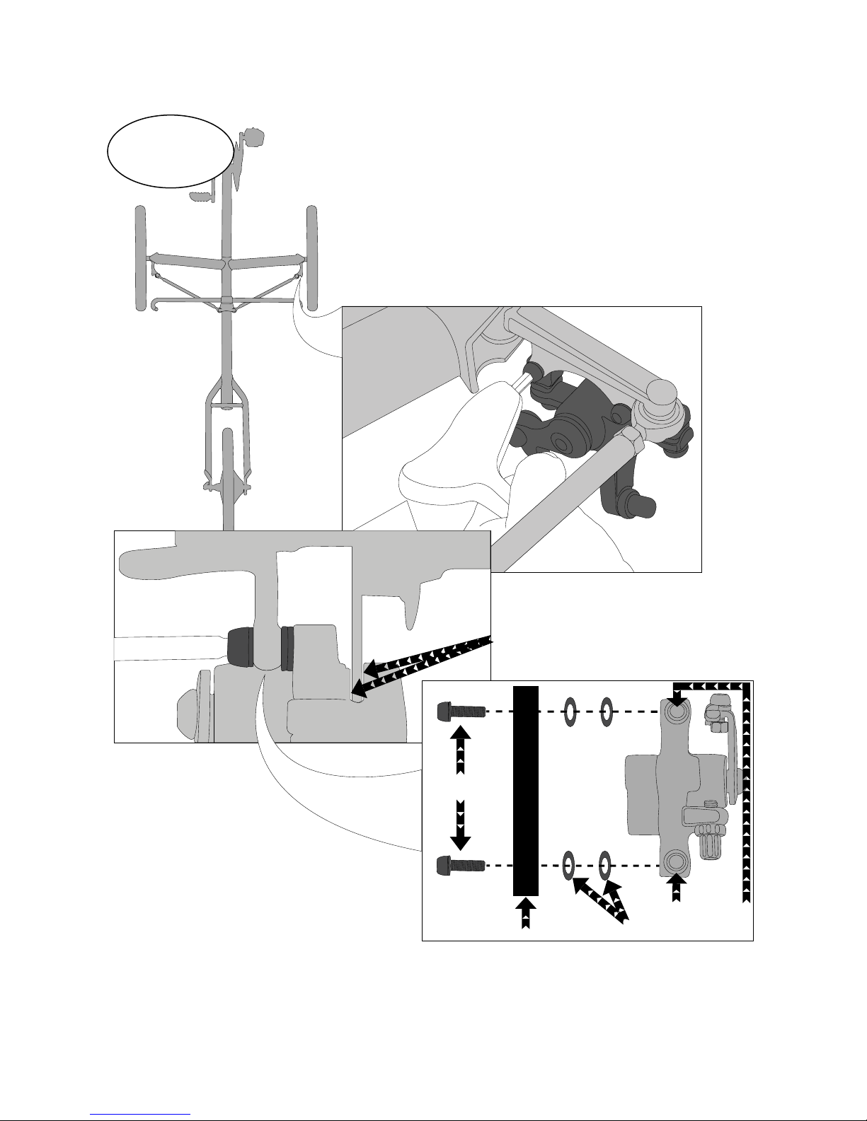
Top
Mounted
Caliper
Bottom
Mounted
Caliper
Proper setup: you should see daylight on either side of the rotor with
bolt screws tightened down. See
below image for bolt location and
fastener layout.
Hubmount
M6 washers OR Fender stay
Caliper Bolts
Mounting
Bolts
10
Brake Caliper Installation
6
 Loading...